ETI 549 Metal Detector - Geotech
ETI 549 Metal Detector - Geotech
ETI 549 Metal Detector - Geotech

You also want an ePaper? Increase the reach of your titles
YUMPU automatically turns print PDFs into web optimized ePapers that Google loves.
Electronics Today International, Feb. 1977, Copyright © Wimbourne Publishing<br />
<strong>ETI</strong> Project <strong>549</strong><br />
INDUCTION BALANCE<br />
METAL DETECTOR<br />
A really sensitive design operating on a different principle from that of other published circuits. This Induction Balance<br />
circuit will really sniff out those buried coins and other items of interest at great depths depending on the size of the object.<br />
“ANOTHER METAL LOCATOR,” some of you will say.<br />
Yes and no. Several designs have been published in the hobby<br />
electronics magazines; some good, some downright lousy but<br />
they have invariably been Beat Frequency Oscillator (BFO)<br />
types. There’s nothing wrong with this principle - they are at<br />
least easy to build and simple to set up. The design described<br />
here works on a very different principle, that of induction<br />
balance (IB). This is also known as the TR principle (Transmit-<br />
Receive).<br />
All metal locators have to work within a certain frequency<br />
band to comply with regulations and a licence is necessary to<br />
operate them. This costs £1.20 for five years and is available<br />
from the Ministry of Posts and Telecommunications, Waterloo<br />
Bridge House, Waterloo Road, London S.E.1.<br />
First a word of warning. The electronic circuitry of this<br />
project is straightforward and should present no difficulty even<br />
to the beginner. However, successful operation depends almost<br />
entirely upon the construction of the search head and its coils.<br />
This part accounts for three-quarters of the effort. Great care,<br />
neatness and patience is necessary and a sensitive ‘scope,<br />
though not absolutely essential, is very useful. It has to be<br />
stated categorically that sloppy construction of the coil will (not<br />
may) invalidate the entire operation.<br />
IB VERSUS BFO<br />
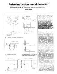
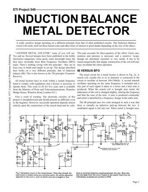
The usual circuit for a metal locator is shown in Fig. 2a. A<br />
search coil, usually 6in or so in diameter is connected in the<br />
circuit to oscillate at between 100-150kHz. A second internal<br />
oscillator operating on the same frequency is included and a<br />
tiny part of each signal is taken to a mixer and a beat note is<br />
produced. When the search coil is brought near metal, the<br />
inductance of the coil is changed slightly, altering the frequency<br />
and thus the tone of the note. A note is produced continually<br />
and metal is identified by a frequency change in the audio note.<br />
The IB principal uses two coils arranged in such a way that<br />
there is virtually no inductive pick-up between the two. A<br />
modulated signal is fed into one. When metal is brought near,<br />
Page 1
Electronics Today International, Feb. 1977, Copyright © Wimbourne Publishing<br />
the electromagnetic field is disturbed<br />
and the receiver coil picks up an<br />
appreciably higher signal.<br />
However, it is impractical for there to<br />
be no pickup - the two coils are after all<br />
laid on top of each other. Also our ears<br />
are poor at identifying changes in audio<br />
level. The circuit is therefore arranged<br />
so that the signal is gated and is set up<br />
so that only the minutest part of the<br />
signal is heard when no metal is<br />
present. When the coil is near metal,<br />
only a minute change in level becomes<br />
an enormous change in volume.<br />
BFO detectors are not as sensitive as<br />
IB types and have to be fitted with a<br />
Faraday screen (beware of those which<br />
aren’t - they’re practically useless) to<br />
reduce capacitive effects on the coil.<br />
They are however, slightly better than<br />
IB types when it comes to indentifying<br />
exactly where the metal is buried - they<br />
can pin-point more easily.<br />
Our detector is extremely sensitive -<br />
in fact a bit too sensitive for some<br />
applications! For this reason we’ve<br />
included a high-low sensitivity switch.<br />
You may ask why low sensitivity is<br />
useful. As a crude example, take a coin<br />
lying on a wooden floor: on maximum<br />
sensitivity the detector will pick up the<br />
nails, etc., and give the same readings as for the coin, making it<br />
difficult to find.<br />
Treasure hunting is an art and the dual sensitivity may only<br />
be appreciated after trials.<br />
Table 1 gives the distances at which various objects can be<br />
detected. These are static readings and only give an indication<br />
of range. If you are unimpressed with this performance you<br />
should bear two things in mind: first compare this with any<br />
other claims (ours are excellent and honest) and secondly bear<br />
in mind how difficult it is to dig a hole over 1 ft of ground<br />
every time you get a reading. Try it - it’s hard work!<br />
COMPONENT CHOICE<br />
The injunction Q1 is not the normal 2N2646; we found<br />
several examples of these erratic in their level - we are talking<br />
about tiniest fractions of one per cent which would normally<br />
not matter, but it does in this circuit. Even some examples of<br />
the TIS43 did not work well - see the note in How it Works.<br />
Secondly Q2 is deliberately a plastic type. <strong>Metal</strong> canned<br />
transistors usually have the collector connected to the case and<br />
due to the nature of the circuit we noted a very small change in<br />
signal level due to capacitive effects when metal can types were<br />
used.<br />
We have specified Q3 and Q4 types as BC109C (highest gain<br />
group) for although lower gain transistors worked for us they<br />
left little reserve of level on RV1 and really low gain types may<br />
not work at all.<br />
RV1 is the critical control and should be a high quality type -<br />
it will be found that it has to be set very carefully for proper<br />
operation.<br />
The choice of an LM380 may seem surprising as only a small<br />
part of its power can be utilised with battery operation. It is<br />
however inexpensive and widely available unlike the<br />
alternatives (note it does not require d.c. blocking at the input).<br />
Output is connected for an 8 ohm speaker and to headphones.<br />
Stereo types are the most common and the wiring of the jack<br />
socket is such that the two sections are connected in series<br />
presenting a l6 ohm load (this reduces current consumption<br />
from the battery).<br />
CONSTRUCTION: CONTROL BOX<br />
The majority of the components are mounted on the PCB<br />
shown in Fig. 3. Component overlay and the additional wiring<br />
is shown in Fig. 4.<br />
Exceptional care should be taken to mount all components<br />
firmly to the board. The trimmer capacitor CV1 is mounted at<br />
right-angles to the board, its tags being bent over and soldered<br />
Page 2
Electronics Today International, Feb. 1977, Copyright © Wimbourne Publishing<br />
firmly to the copper pads. This enables it to be<br />
trimmed with the box closed. A plastic trimming<br />
tool should be used if possible. Poor connections<br />
or dubious solder joints may be acceptable in<br />
some circuits - not in this one. Take care to<br />
mount the transistors, diodes and electrolytic<br />
capacitors the right way around.<br />
The PCB is fitted into the control box by<br />
means of long screws and pillars. The control<br />
box has to be drilled to take the speaker, the pots,<br />
switches, headphone jack and the cable from the<br />
search head.<br />
THE HANDLE ASSEMBLY<br />
The handle is made totally from standard parts.<br />
The general construction can be seen in Fig. 5.<br />
This is made from Marley 22mm cold water<br />
plumbing available from many plumbing shops.<br />
The hand grip is that for a bicycle - also easily<br />
available and a perfect fit onto the plastic pipe. A<br />
right-angled elbow and two sleeve connectors<br />
are specified. The elbow should be glued firmly<br />
and one end of each of the connectors should be<br />
glued also.<br />
The reason for the connector near the base is<br />
to facilitate easy removal of the head and the<br />
control box for testing and initial setting up.<br />
The control box is held to the handle by means<br />
of two pipe clips - again available from<br />
plumber’s merchants.<br />
The connection to the search head is by means<br />
of a 4-1/2in length of tubing which has to be<br />
modified. Put 1-1/2in of this tube into boiling<br />
water for about half a minute to soften the<br />
plastic, take it out and quickly clamp it into a<br />
vice to flatten half the length, at the same time<br />
bending the flat to about 45 degrees. This will<br />
now lie across the top of the search head and is<br />
glued into position and held by a single 2BA<br />
nylon nut and bolt through the top of the search<br />
head.<br />
THE COIL<br />
Remember this is the key to the whole<br />
operation. The casing of the coil is not so critical<br />
but the layout is.<br />
It is best first to make the 8mm plywood circle<br />
to the dimensions shown in Fig. 5. A circle of<br />
thinner plywood or hardboard is then firmly<br />
clued onto this - it’s fairly easy to cut this after<br />
glueing. Use good quality ply and a modern<br />
wood glue to make this.<br />
HOW IT WORKS - <strong>ETI</strong> <strong>549</strong><br />
Q1, Q2 and associated components form the transmitter section of the circuit. Q1 is a<br />
unijunction which operates as a relaxation oscillator, the audio note produced being determined<br />
by R1 and C1. The specified components give a tone of roughly 800Hz. R1 can lie in the range<br />
33k to 1OOk if a different audio frequency is desired.<br />
Q2 is connected as a Colpitt’s oscillator working at a nominal 130kHz; this signal is heavily<br />
modulated by C3 feeding to the base of Q2. In fact the oscillator produces bursts of r.f. at 800Hz.<br />
L1 in the search head is the transmitter coil.<br />
L2 is arranged in the search head in such a way that the minimum possible signal from L1 is<br />
induced into it (but see notes on setting up). On all the prototypes we made we reduced this to<br />
about 20mV peak-to-peak in L2. L2 is tuned by C6 and C7 and peaked by CV1 and feeds to the<br />
base of Q3, a high gain amplifier. This signal (which is still modulated r.f.) is detected by D1, D2<br />
providing the bias for D1. The r.f. is eliminated by C10 and connects to the level control RV1.<br />
The signal is further amplified by Q4 which has no d.c. bias connected to the base. In no-signal<br />
conditions this will be turned off totally and will only conduct when the peaks of the 800Hz<br />
exceed about O.6V across R11. Only the signal above this level is amplified.<br />
On low sensitivity these peaks are connected to the volume control RV2 (any stray r.f. or very<br />
sharp peaks being smoothed by C15) and fed to the IC amplifier and so to the speaker.<br />
The high sensitivity stage Q6 is connected at all times and introduces another gating stage<br />
serving the same purpose as the earlier stage of Q5. This emphasises the change in level in L2<br />
even more dramatically. Note that RV1 has to be set differently for high and low sensitivity<br />
settings of SW1.<br />
Whichever setting is chosen for SW1, RV1 is set so that a signal can just be heard. In practice<br />
it will be found that between no-signal and moderate-signal there is a setting for RV1 where a<br />
‘crackle’ can be heard. Odd peaks of the 800Hz find their way through but they do not come<br />
through as a tone. This is the correct setting for RV1.<br />
The stage Q6 also feeds the meter circuit. Due to the nature of the pulses this need only be very<br />
simple.<br />
Since we are detecting really minute changes in level it is important that the supply voltage in<br />
the early stages of the receiver are stabilised, for this reason ZD1 is included to hold the supply<br />
steady independent of battery voltage (which will fall on high output due to the current drawn by<br />
IC1).<br />
It is also important that the supply voltage to Q1 and Q2 does not feed any signal through to<br />
the receiver. If trouble is experienced (we didn’t get any) a separate 9V battery could be used to<br />
supply this stage.<br />
lC1 is being well underused so a heatsink is unnecessary.<br />
Battery consumption is fairly high on signal conditions - between 60mA and 80mA on various<br />
prototypes but this will only be for very short periods and is thus acceptable. A more modest<br />
20mA or so is normal at the ‘crackling’ setting.<br />
Stereo headphones are used and are connected in series to present 16 ohms to IC1 reducing<br />
current consumption.<br />
Selection of Q1 and Q2<br />
We found that Q1 and to a lesser extent Q2 required careful selection. Q1 should be chosen for<br />
the minimum possible ‘crackle’ - so that the transition from no-signal to hearing the 800Hz is as<br />
definite as possible. Some transistors for Q1 and Q2 can produce higher odds peaks than others.<br />
Page 3
Electronics Today International, Feb. 1977, Copyright © Wimbourne Publishing<br />
Resistors<br />
R1 47k 1/4W, 5%<br />
R2 270R 1/4W, 5%<br />
R3 150k 1/4W, 5%<br />
R4 39k 1/4W, 5%<br />
R5, 14 1k 1/4W, 5%<br />
R6, 15 180R 1/4W, 5%<br />
R7, 9 1M8 1/4W, 5%<br />
R8, 10, 11, 12 ,13<br />
Potentiometers<br />
4k7 1/4W, 5%<br />
RV1 4k7 log rotary<br />
RV2<br />
Capacitors<br />
4k7 log rotary<br />
C1, 8, 16 47µF 16v electrolytic<br />
C2, 3, 11, 14, 18 100nF ceramic etc.<br />
C4 3n3 polystyrene 5%<br />
C5 10n polystyrene 5%<br />
C6, 7 5n6 polystyrene 5%<br />
C9, 10, 12, 13, 15 20n ceramic etc.<br />
C17 470µF 16v electrolytic<br />
C19 4µ7 16v electrolytic<br />
CV1 500p trimmer<br />
PARTS LIST - <strong>ETI</strong> <strong>549</strong><br />
Semiconductors<br />
Q1 TIS43 Unijunction<br />
Q2 2N2926 - see text<br />
Q3, 4 BC109C<br />
Q5, 6 BC108<br />
IC1 LM380 14 pin DIL<br />
D1, 2, 3, 4 OA91<br />
ZD1 6.2 volt 400mW zener diode<br />
Miscellaneous<br />
SW1 SW2, 2 pole, 2 way slide switches<br />
Stereo jack socket<br />
Miniature (2-1/4 in etc) 8 ohm loudspeaker<br />
L1, L2 - See text and drawings<br />
Vero box (65-2520J)<br />
PCB Board, <strong>ETI</strong> <strong>549</strong><br />
4 core, individually screened cable, 1.5 metres<br />
Battery clip (PP6)<br />
Battery (PP6)<br />
Wood and laminate for search head<br />
2 control knobs, 2BA nylon nut bolt<br />
M1 signal level meter, 150µA movement<br />
Marley 22mm cold water plumbing (see text)<br />
Bicycle grip<br />
Page 4
Electronics Today International, Feb. 1977, Copyright © Wimbourne Publishing<br />
This now forms a dish into which the coils are<br />
fitted. The plastic connector to the handle should<br />
be fitted at this stage.<br />
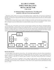
You’ll now have to find something cylindrical<br />
with a diameter of near enough 140mm (5-1/2in).<br />
A coil will then have to be made of 40 turns of 32<br />
s.w.g. enamelled copper wire. The wire should be<br />
wound close together and kept well bunched and<br />
taped to keep it together when removed from the<br />
former. Two such coils are required, both are<br />
identical.<br />
One of the coils is then fitted into the ‘dish’ and<br />
spot clued in six or eight places using quick setting<br />
epoxy resin: see photograph of the approximate<br />
shape.<br />
L2 is then fitted into place, again spot gluing it<br />
not in the area that it overlaps L1. The cable<br />
connecting the coil to the circuit is then fed<br />
through a hole drilled in the dish and connected to<br />
the four ends. These should be directly wired and<br />
glued in place, obviously taking care that they<br />
don’t short. The cable must be a four-wire type<br />
with individual screens - the screens are left<br />
unconnected at the search head.<br />
You will now need the built up control<br />
box and preferably a scope. The transmit<br />
circuit is connected to L1. The signal<br />
induced into L2 is monitored; at first this<br />
may be very high but by manipulating L2,<br />
bending it in shape etc., the level will be<br />
seen to fall to a very low level. When a very<br />
low level is reached, spot glue L2 until only<br />
a small part is left for bending.<br />
Ensure that when you are doing this that<br />
you are as far away from any metal as<br />
possible but that any metal used to mount<br />
the handle to the head is in place. Small<br />
amounts of metal are acceptable as long as<br />
they are taken into account whilst setting up.<br />
Now connect up the remainder of the<br />
circuit and set RV1 so that it is just passing<br />
through a signal to the speaker. Bring a<br />
Page 5
Electronics Today International, Feb. 1977, Copyright © Wimbourne Publishing<br />
piece of metal near the coil and the signal<br />
should rise. If it falls in level (i.e. the<br />
crackling disappears) the coil has to be<br />
adjusted until metal brings about a rise with<br />
no initial falling. CV1 should be adjusted for<br />
maximum signal, this has to be done in<br />
conjunction with RV1.<br />
Monitoring this on a scope may mean that<br />
the induced signal is not at its absolute<br />
minimum: this doesn’t matter too much. Now<br />
add more spot gluing points to L2.<br />
You should now try the metal locator in<br />
operation. If RV1 is being operated entirely<br />
at the lower end of its track, making setting<br />
difficult, you can select a lower gain<br />
transistor such as a BC108 for Q4.<br />
When you are quite certain that no more<br />
manipulation of the coils will improve the<br />
performance, mix up plenty of epoxy resin<br />
and smother both coils, making certain that<br />
you don’t move them relative to each other.<br />
The base plate can then be fitted to enclose<br />
the coil, this should be glued in place.<br />
USING THE METAL LOCATOR<br />
You will find that finding buried metal is<br />
rather too easy. 95% will be junk - silver<br />
paper being a curse. The search head should<br />
be panned slowly over the surface taking care<br />
to overlap each sweep: the sensitive area is<br />
somewhat less than the diameter of the coil.<br />
This type of locator will also pick up some<br />
materials which are not metal - especially<br />
coke and it is also not at its best in wet grass.<br />
Think very carefully about where you want<br />
to search: this is more important than actually<br />
looking. The area you can cover thoroughly<br />
is very, very small, but is far more successful<br />
than nipping all over the place. As an<br />
example of how much better a thorough<br />
search is, we thoroughly tried on 25 square<br />
feet of common ground (5ft x 5ft); we found<br />
over 120 items but a quick search initially had revealed only<br />
two!<br />
Treasure hunting is growing in popularity and those who do<br />
it seriously have adopted a code; essentially this asks you to<br />
respect other people’s property, to fill in the holes you dig and<br />
to report any interesting finds to museums. And do get a licence<br />
- it must be the best bargain available at 25p a year (rather<br />
£1.20 for five years).<br />
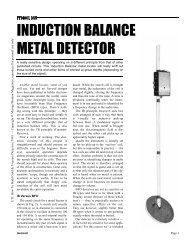
METER CIRCUIT<br />
Since the circuit is basically sensing a change in audio level,<br />
a meter circuit can be incorporated. For the very first indication<br />
from the ‘crackle’<br />
(see later) to heavy<br />
crackle your ears are<br />
likely to be more<br />
sensitive than the<br />
meter but thereafter it<br />
will come into its<br />
own.<br />
This part of the<br />
circuit is optional and<br />
the components are<br />
not included on the<br />
board.<br />
Page 6