Metal detector uses single IC - Geotech
Metal detector uses single IC - Geotech
Metal detector uses single IC - Geotech

You also want an ePaper? Increase the reach of your titles
YUMPU automatically turns print PDFs into web optimized ePapers that Google loves.
<strong>Metal</strong> <strong>detector</strong> <strong>uses</strong> <strong>single</strong> <strong>IC</strong><br />
RACHEL AND STEVE HAGEMAN, HEWLETT-PACKARD, SANTA ROSA, CA<br />
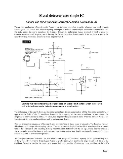
The original application of the circuit in Figure 1 was to locate coins, but it applies wherever you need to locate<br />
metal objects. The circuit <strong>uses</strong> a beat-frequency technique: Whenever a metal object comes close to the search coil,<br />
the metal ca<strong>uses</strong> the coil’s inductance to decrease. Though the inductance change is small in itself (a coin, for<br />
example, ca<strong>uses</strong> a small frequency shift), beating the frequency against that of another fixed oscillator at almost the<br />
same frequency produces a noticeable audio-frequency shift.<br />
Beating two frequencies together produces an audible shift in tone when the search<br />
coil in this simple metal <strong>detector</strong> comes near a metal object.<br />
The inductance of the search loop and the input capacitance (series combination of the three input capacitors, or<br />
approximately 2nF) of the Q1 oscillator determine the frequency of the search oscillator. In this design, the<br />
frequency is approximately 370kHz. For years, this frequency has prevailed in metal <strong>detector</strong>s, because it yields the<br />
lowest sensitivity to ground conditions, such as moisture and density.<br />
You can change the inductance of the search coil by modifying its turns count or diameter. The loop has Faraday<br />
shielding to reduce capacitive-coupling effects. You can fabricate a simple Faraday shield by using adhesive copper<br />
tape of the sort used in EMI shielding. Simply wrap the completed loop with the foil tape. Make sure the tape has a<br />
gap at one point around the loop, or a shorted-turn transformer results. You should mechanically secure the loop to a<br />
nonmetallic form to prevent microphonics.<br />
With the prescribed 4-in. diameter, the search coil in this design lets you detect a penny buried approximately 2 in.<br />
in the ground. If you wish to detect larger objects at greater depths, you can build a larger search coil. To keep the<br />
oscillator frequency roughly the same, you should halve the number of turns for every doubling of the coil’s<br />
Page 1
diameter. The Q2 beat oscillator <strong>uses</strong> a similar Colpitts design. However, instead of using inductance changes for<br />
tuning, the beat oscillator <strong>uses</strong> a varactor diode. Depending on your exact search-coil inductance (hence, oscillation<br />
frequency), you may need to adjust L1 to obtain adequate tuning range in the beat oscillator.<br />
Both oscillators have light coupling to the remaining audio section of the LM389. The amplifier, whose gain is<br />
approximately 26dB, easily drives a set of 8 ohm headphones. If you need more gain, you can add a 10uF capacitor<br />
between pins 4 and 12 of the LM389. The prototype <strong>detector</strong> <strong>uses</strong> some polyvinyl-chloride sprinkler pipes and<br />
fittings to provide a convenient handle and chassis for the electronics. Operating the metal <strong>detector</strong> is simple. Place<br />
the search coil on the ground, and adjust the tune potentiometer for a tone of approximately 100Hz. Then, taking<br />
care to keep the search coil at a fixed distance from the ground, slowly sweep the coil over the area of interest.<br />
<strong>Metal</strong> objects cause a change in the audible tone. The relative amount of tone shift indicates the object’s size and<br />
depth. The greater the tone shift, the bigger or closer the object is. You should avoid "zero beating" the two<br />
oscillators, because they will lock with each other, thereby reducing the search oscillator’s sensitivity. You can add a<br />
meter output for visual or automatic control by adding a highpass filter to the LM389’s output. This highpass output,<br />
operated below the corner frequency, changes in amplitude as the frequency increases. Rectifying the output yields a<br />
positive indication of the metal object’s proximity to the search coil. By digitizing the meter output and using a<br />
<strong>single</strong>-chip uP with a DAC to control the beat oscillator, you can make a complete closed-loop control system for<br />
industrial applications.<br />
EDN DECEMBER 18, 1997<br />
Page 2