
Create successful ePaper yourself
Turn your PDF publications into a flip-book with our unique Google optimized e-Paper software.
<strong>“PHASER”</strong><br />
<strong>METAL</strong> <strong>DETECTOR</strong><br />
BY THE PROF<br />
THE SOUND OF XNORING<br />
Producing a new metal detector design for the home constructor is not an easy task these days. There have been a large number<br />
of metal detector projects published in the last fifteen to twenty years, making it much easier to come up with a revamped circuit<br />
than one of a totally new type. I will not claim that this detector relies on a totally new system as it works on a principle that has<br />
certainly been known for many years. On the other hand, I have not seen a previously published design of this type. The basic<br />
requirements for this project were as follows:<br />
1. It should not be of a “standard” (BFO, IB, or PI) type.<br />
2. It should be free from the “ground” effect without using any special shielding. The ground effect is one that results in an<br />
indication being produced by certain types of detector even when no metal is present in the ground.To combat this effect either<br />
the search coil must be suitably shielded, or the coil must be kept a fixed distance above the ground.<br />
3. Construction of the search coil should be non-critical, and any electronic setting up should be simple and straightforward.<br />
4. The unit should be easy to use, having a method of indication that is very obvious even for someone without a good sense of<br />
pitch (many designs indicate the presence of metal by giving a small change in the pitch of an audio tone).<br />
5. It should have a level of performance at least as good as most simple BFO and IB designs.<br />
PHASED OUT<br />
The Prof’s experimental design irons out the ground effect, but<br />
can’t quite grind out the iron effect! Using very low frequencies<br />
(for a metal detector) it uses small phase shifts in the search<br />
signal to trace useful objects.<br />
When looking at the available options, the only kind of detector which seemed likely to fit these requirements was the very low<br />
frequency (VLF) phase detector type. This operates by detecting small phase changes in the signal in the search coil when metal is<br />
brought near to the coil. “Very low frequency” in metal detector terms generally means a frequency at the upper end of the audio<br />
spectrum, with something around 17KHz being quite typical. The point of using relatively low operating frequencies in metal<br />
detectors is that it avoids problems with the ground effect.<br />
Practical experiments with VLF phase detector circuits proved quite encouraging. and the final design is quite simple but<br />
effective. In terms of performance it falls some way short of a kit-built IB unit that I have, but it can be built for what I would<br />
estimate at little more than a tenth of the price of this commercial unit. The higher sensitivity of ultra-sensitive detectors is often<br />
unusable anyway, due to problems with small amounts of iron or other metals in the soil giving a sort of pseudo-ground effect.<br />
The performance of the unit is quite good for such a simple design. It will detect a 20p coin at a maximum range of about 60 to<br />
80 millimetres. Larger pieces of metal can be detected at longer ranges, with a 50p coin being detectable at about 100 to 150<br />
millimetres. Large chunks of metal can be detected at a maximum range of around 500 millimetres. This is better than most BFO<br />
designs, but is perhaps a little inferior to some simple IB circuits. This design is more simple than an IB design though, and in<br />
particular, the search coil does not need to be made very accurately. In this respect the unit is even less critical than a BFO design.<br />
Sensitivity is certainly high enough to provide good results. Note that the quoted sensitivities were obtained from “in-air” tests.<br />
Performance in practice depends on the characteristics of the soil, and the exact orientation of many objects seems to significantly<br />
affect how well (or otherwise) they are detected.<br />
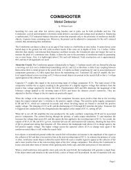
The block diagram of Fig. 1 shows the arrangement used in this detector. The search coil is actually a twin type, and is really a<br />
form of transformer. An audio oscillator drives the primary winding by way of a buffer amplifier. The purpose of the buffer is to<br />
ensure that metal close to the search coil does not “pull” the oscillator and affect the phasing of its output signal. It is not to<br />
produce a high drive current in the search coil, which only requires a very low drive level. A (more or less) squarewave signal is<br />
produced by the oscillator.<br />
The output from the secondary winding is fed to a high gain amplifier and then to a trigger circuit. This gives a roughly<br />
squarewave signal at logic compatible signal levels. A form of mixer circuit processes the output of the audio oscillator and the<br />
output of the trigger circuit. This mixer is actually a 2 input xnor gate. XOR and xnor gates are probably the least used types, and<br />
Page 1
some readers may not be familiar with their operation. An ordinary nor gate has an output which goes low if either input 1 OR<br />
input 2 is taken high. The output also goes low if both input 1 AND input 2 are taken high. An xnor gate differs from a nor type<br />
only in that taking both inputs high does not take the output low. An xnor gate therefore provides what could reasonably be<br />
regarded as the true nor action.<br />
What we require in this application is a<br />
mixer circuit that converts phase lag into a<br />
proportional output voltage, because the<br />
output from the secondary winding slightly<br />
lags the input signal, but if metal is brought<br />
near the search coil the phase lag increases<br />
and decreases for ferrous and non-ferrous<br />
metals respectively. XOR and xnor gates<br />
may not seem to be of much use as phase<br />
detectors, but they can in fact operate very<br />
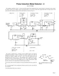
well in this mode. The waveforms in Fig. 2<br />
help to explain the way in which this type of<br />
detector operates. Here we are assuming that<br />
an xor gate is used.<br />
The top set of three waveforms are those<br />
obtained with the two input signals perfectly<br />
in-phase. Both inputs of the gate are low,<br />
then they are both high, then low again, and<br />
so on. A state is never reached where the<br />
inputs are at opposite states, and so the<br />
output goes continuously low. In the middle<br />
set of waveforms the second input lags the<br />
first one by about 45 degrees. The two inputs<br />
are now at opposite states twice on each<br />
cycle, although only briefly. The output is<br />
high for about 25% of the time, giving an<br />
average output voltage of around one quarter<br />
of the supply voltage. In the bottom set of<br />
waveforms the phase lag has been increased<br />
to 90 degrees. This lengthens the periods<br />
during which the input signals are at opposite<br />
states, and gives longer output pulses, still<br />
with two per input cycle. The average output<br />
voltage is increased to about 50% of the<br />
supply voltage. By taking the two input<br />
signals 180 degrees out of phase the two<br />
signals would always be at opposite states, and the output would go permanently high. An xnor gate is effectively an xor type<br />
with its output inverted. Results using an xnor gate are therefore essentially the same, but the output is of the opposite logic state.<br />
By smoothing the output pulses to obtain a reasonably ripple-free output equal to the average output potential, the required<br />
phase lag to voltage conversion is obtained. However, the phase changes produced by even quite large pieces of metal very close<br />
to the search coil are quite small. At most they seem to be just a few degrees, and small target objects more than a few millimetres<br />
from the search coil produce a phase shift of only a fraction of a degree. A high gain dc amplifier is therefore needed in order to<br />
produce a reasonably strong output signal to drive the subsequent stages. There is quite a large phase lag under stand-by<br />
conditions, giving a strong quiescent output voltage from the unit. A variable bias circuit in the dc amplifier enables this quiescent<br />
output voltage to be nulled.<br />
The output stages of the unit are used to produce an audio tone that rises or falls in volume when metal is detected. Even people<br />
who have a good sense of pitch generally find a change in volume much more noticeable than a change in pitch. The output from<br />
the dc amplifier could be used to drive a panel meter if this method of indication is preferred. However, in my experience it is<br />
necessary to concentrate on control of the search head, making any form of visual indicator difficult to use properly.<br />
A tone at a frequency of a few hundred Hertz is obtained by feeding the output of the audio oscillator stage through a frequency<br />
divider circuit. This drives a chopper circuit which produces an audio output signal having a peak to peak amplitude equal to the<br />
Page 2
output voltage from the dc amplifier. This signal is fed to a buffer stage which drives the output socket. A crystal earphone and<br />
most types of headphone are suitable for use with this project.<br />
CIRCUIT OPERATION<br />
The full circuit diagram for the “Phaser” metal detector appears in Fig. 3. The audio oscillator is a humble 555 astable circuit. A<br />
low power version of the 555 (the TLC555CP) is used in the IC1 position in order to reduce the current consumption and extend<br />
the battery life. The operating frequency of the circuit is roughly 16KHz. The primary of the search coil (T1) is driven via an<br />
emitter follower buffer stage based on TR1. R3 limits the drive current to just a few milliamps. Both the primary and secondary<br />
windings of T1 are fitted with parallel “tuning” capacitors, and these seem to be essential if reasonable sensitivity is to be<br />
achieved. IC2 amplifies the output of the secondary winding, and the high gain of this amplifier gives a severely clipped output<br />
signal. VR1 is adjusted to give an output waveform having a suitable mark-space ratio.<br />
This signal is processed by IC3a which is a cmos xnor gate which functions here as a simple inverter stage. IC3b is the xnor<br />
gate which functions as the phase detector and it is fed from the outputs of IC1 and IC3a. Its output is smoothed to a reasonably<br />
low ripple dc signal by the single pole lowpass filter comprised of R6 and C6. IC4 acts as the basis of the dc amplifier, and this<br />
has a voltage gain of around 300 to 400 times. I cut down the voltage gain from its original level as I preferred lower drift to<br />
increased sensitivity. If you prefer higher sensitivity, then R7 can be made higher in value and (or) R8 can be replaced with a<br />
shorting link. Remember though, that the increased gain will result in any drift being amplified by a larger amount, and more<br />
frequent readjustment will be needed in order to keep the circuit adjusted for optimum sensitivity. Also, accurate adjustment of<br />
the bias controls becomes more difficult. These controls are VR2 (“fine”) and VR3 (“coarse”). C7 provides additional filtering<br />
which provides a very low ripple dc output signal.<br />
The frequency divider is a cmos 4040BE 12-stage binary type (lC5). In this circuit only five stages are used. This gives a divide<br />
by 32 action, and an output frequency of about 500Hz. This signal is used to drive common emitter switching transistor TR2,<br />
which chops the output of IC4. VR4 is the collector load for TR2, and this acts as the volume control. TR3 is an emitter follower<br />
output stage.<br />
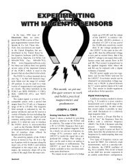
A very stable supply in the range 9 to 15 volts is required. A single 9 volt battery is unsuitable as it would provide totally<br />
inadequate stability. Instead, two 9 volt batteries wired in series are used to provide a basic 18 volt supply, and monolithic voltage<br />
generator IC6 then provides a well stabilised 12 volt output from this. R14 reduces the dissipation in IC6 slightly, so that it<br />
operates slightly cooler and gives a more stable output The current consumption of the circuit is about 17 milliamps. This can be<br />
provided by two high power PP3 size batteries or rechargeable PP3 size nickel-cadmium batteries. If the unit is likely to receive a<br />
Page 3
great deal of use it would probably be better to opt for higher capacity batteries, such as two sets of six HP7 size cells in plastic<br />
holders.<br />
CIRCUIT BOARD<br />
Fig. 4 shows the component layout for the printed circuit board. IC1 to IC5 are all mos types and consequently require the<br />
normal mos anti-static handling precaution to be observed. Note that IC1 has the opposite orientation to ICs 2, 3, and 4. Three link<br />
wires are required, and these can be made from 22 swg tinned copper wire (or trimmings from resistor leadout wires). The<br />
capacitors are all miniature printed circuit (vertical) mounting types. It could be difficult to use capacitors having the wron g<br />
physical characteristics, especially in the case of the polyester capacitors which should have 7.5 millimetre leadspacing. Be<br />
careful to fit the electrolytic capacitors with the correct polarity. At this stage of the proceedings only fit single-sided pins to the<br />
board at the points where connections to off-board components will eventually be made. Once fitted, generously tin the pins with<br />
solder.<br />
The unit will fit into a case having dimensions of about 150 by 80 by 50 millimetres, but this assumes that two PP3 size<br />
batteries will be used as the power source. If you opt for larger batteries such as a number of HP7 size cells a substantially larger<br />
case will be required. The case will eventually be fixed vertically on the stem of the unit. The controls and output socket are<br />
mounted on what becomes the lower section of the removable front panel. This leaves sufficient space for the batteries in the top<br />
section of the case. The component panel is mounted on the rear panel of the case using M3 or 6BA fixings, including some extra<br />
nuts or short spacers to hold it slightly clear of the rear panel. Note though, that printed circuit board can not be finally fitted in<br />
place until the case has been mounted on the stem of the unit.<br />
All the point-to-point style wiring is quite straightforward and should not give any great difficulties. Fig. 5 in conjunction with<br />
Fig. 4 shows the interconnections between the three potentiometers, the output socket, and the circuit board. SK1 is a 3.5<br />
millimetre jack socket on the prototype. I use the unit with a crystal earphone, or “Walkman” type headphones having their<br />
original (stereo) plug replaced with an ordinary mono type. The latter, with the two earphones wired in series, seem to give better<br />
volume and better results than a crystal earphone, and are probably worth the extra cost. Of course, rather than fit a different plug<br />
to the phones you might prefer to fit a stereo 3.5 millimetre jack in the SK1 position, but sockets of this type can be difficult to<br />
obtain. The unit seems to work with most types of headphone, incidentally. For low and medium impedance types it is best to use<br />
series connection, but for high impedance headphones parallel connection will probably be better. A low impedance magnetic<br />
earphone is unlikely to give satisfactory results.<br />
MECHANICAL CONSTRUCTION<br />
Mechanically, construction of the detector is non-critical. You can opt for a fairly basic method of construction (as I did), or<br />
adopt more advanced techniques to give a more professional finish. Results using the unit will be exactly the same either way, and<br />
it is only the quality of finish that will be different. The method of construction suggested here is a basic one that anyone who is<br />
Page 4
easonably practical should be able to tackle without any real difficulty. It uses inexpensive and readily obtainable parts. It is up to<br />
you whether you follow this method of construction or try something a bit more difficult. If you do try out some ideas of your<br />
own there are a few points to bear in mind.<br />
Unlike some types of metal locator, with a VLF phase detector a certain amount of metal within or near the search head is quite<br />
acceptable. The electronics can be adjusted to null this metal, and there is no obvious loss of sensitivity even with quite large<br />
amounts of metal close to the search coil. It is therefore quite in order to have a metal stem fixed to the search head by a metal<br />
bracket. It might even be acceptable to have the search head constructed from metal, but I have not tried this and cannot guarantee<br />
that it will provide satisfactory results. Physical balance is important as the unit will be difficult to use for long periods if it is top<br />
or bottom heavy. It is possible to produce a very neat search head using fibreglass, but as I know from previous experience, this<br />
can result in a very bottom heavy and unwieldly finished unit. If you use a heavy-weight material for the search head use as little<br />
of it as possible! The handle should be as close to the centre of balance as possible.<br />
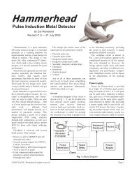
The method of construction I adopted is as<br />
outlined in Fig. 6. The stem is a piece of<br />
wooden dowel about 20 to 25 millimetres in<br />
diameter and around 1.2 to 1.3 metres long.<br />
Suitable dowels are readily available as<br />
replacement broom handles! The bottom end<br />
of the stem is angled at about 55 degrees to<br />
the search head, and it must be cut at the<br />
appropriate angle. The search head is made<br />
from thin hardboard or particle board. The<br />
material I used was thin particle board with a<br />
white plastic veneer on both surfaces. Apart<br />
from giving a neat finish the veneer also<br />
helps to make the unit weatherproof. The<br />
search head is really just an outside bobbin<br />
on which T1 is wound. Two pieces of the<br />
board about 200 by 150 millimetres form the<br />
top and bottom cheeks, while one or two<br />
pieces about 140 by 100 millimetres form the<br />
middle section of the bobbin. It is advisable<br />
to trim off the corners of the larger pieces<br />
and then round them off using a sander. This<br />
gives a neater appearance and avoids having<br />
sharp corners which can tend to get tangled<br />
in the undergrowth when searching overgrown ground. The three or four pieces of the bobbin are held together by a good quality<br />
adhesive such as an epoxy resin type. Drill three or four small holes (about 1.6 millimetres in diameter) well towards the front of<br />
the top panel. These are where the leads of the connecting cable will pass through the top panel. The search head is fastened to the<br />
stem using a woodscrew and some epoxy resin adhesive.<br />
The case is fixed at the top end of the stem using three small woodscrews. The case must protrude slightly beyond the end of<br />
the stem, or the stem will get in the way and make it impossible to fit one of the circuit board’s mounting screws in place. Having<br />
the case as high up on the stem as possible is a good idea anyway. It gives a better balance and keeps the case clear of the handle<br />
section of the stem (the section just beneath the case). An entrance hole for the cable which connects T1 to the circuit board is<br />
required in the bottom panel of the case, and a grommet should be fitted into this hole.<br />
Twin individually screened cable is the obvious type to use for these interconnections. I found that twin overall screened cable<br />
was also perfectly suitable, with the outer braiding carrying the earth connections for both windings of T1. T1 consists of 100<br />
turns of 36 swg enamelled copper wire for the primary winding, with 25 turns of the same wire laid on top of this to act as the<br />
secondary winding. The windings do not need to be particularly neat, but try to wind them quite tightly. Any turns left popping<br />
around could cause spurious indications from the unit. Prepare the ends of the screened cable’s leads so that they can be passed<br />
through the holes in the top panel of the search head and connected to TI. At this stage it is probably best to leave these<br />
connections bare, but once the unit has been tested and is fully working it would be advisable to use some fibreglass filler paste or<br />
epoxy adhesive to cover them over and protect them. A cable grip secures the cable to the top of the search head, and some tape<br />
can be used to cover over the cable and produce a neat finish.<br />
Some bands of insulation tape are used to fix the cable to the front edge of the stem. If you have a suitable tool for the purpose<br />
it would be a good idea to make a groove for the cable in the front edge of the stem. About half a dozen bands are sufficient to<br />
hold the cable in place. I used a couple of layers of tape over practically the entire stem in order to give a neat finish and a degree<br />
Page 5
of weather-proofing. I used white tape for most of the stem, with black for the<br />
handle section. To finish off the unit, thread the twin screened cable through<br />
the hole in the case and connect it to the printed circuit board, and paint or<br />
varnish around the edges of the search head so that the hardboard or particle<br />
board is sealed against moisture absorption.<br />
ADJUSTMENT AND USE<br />
If you have access to an oscilloscope, VR1 can be adjusted so that the<br />
output from IC3b is reasonably symmetrical pairs of pulses. In the absence of<br />
suitable test equipment it is just a matter of trying VR1 at various settings in<br />
an attempt to find one that gives good results. Fortunately, adjustment of this<br />
preset seems to be far from critical, and any roughly central setting seems to<br />
give satisfactory results.<br />
When using the unit, set VR2 at a roughly central setting, and turn the<br />
control knob of VR3 fully counter clockwise. With the volume control well<br />
advanced, adjust the control knob of VR3 slowly in a clockwise direction until<br />
a loud tone is heard from the headphones. Then adjust VR2 to reduce the<br />
volume of the tone so that it is quite quiet but still clearly audible. Placing the<br />
search coil close to a metal object should result in the tune increasing or<br />
decreasing in volume. Conventionally, the detector should be set up so that the<br />
tone increases in volume for non-ferrous metals, and decreases in volume for<br />
ferrous types. This is the action that will be obtained if you have the windings<br />
of T1 connected in-phase. I preferred to have items or interest (which mostly<br />
means non-ferrous metals) produce a drop in volume, as I found a small drop<br />
in volume to be much more apparent than a small increase. I therefore wired<br />
the windings of T1 out-of-phase (ie, one “start” lead earthed and one used as<br />
the non-earthy lead). You might like to try out the unit one way, and then<br />
reverse the connections to one winding of T1 so that you can try it out the<br />
other way, to see which system you find easiest to use.<br />
As a point of interest, I found that ferrite rods and pieces of iron had the<br />
opposite effect to most other metals, but steel (which I would have thought<br />
counted as a ferrous metal) usually did not. Note that for optimum sensitivity<br />
you must keep VR2 adjusted so that the tone from the earphones is fairly quiet<br />
under stand-by conditions. The unit inevitably drifts slightly, and VR2 will<br />
accordingly need to be periodically trimmed in order to keep the unit at<br />
optimum sensitivity. Eventually you will find that very frequent adjustment of<br />
VR2 and VR3 is required, and this indicates that the batteries are nearing<br />
exhaustion. There seems to be no problem at all with the ground effect. If an<br />
area of ground always gives a small indication from the unit, this indicates<br />
that the soil has a significant metal content This phenomenon is not as rare as<br />
you might think, and can occasionally make an effective search very difficult.<br />
FINALLY<br />
There are a few final points that it is worth mentioning. I believe that<br />
licenses are no longer needed for metal detectors. To be legally usable in the<br />
UK they must fall within certain restrictions, but to the best of my knowledge<br />
this design falls comfortably within all these restrictions. Constructors outside<br />
the UK should ascertain that the unit can be used legally in their country, and<br />
should obtain any necessary permit prior to constructing and using the unit.<br />
You should obtain permission before searching any land that you do not own.<br />
Any sites of historic interest are out-of-bounds to treasure hunters. If you<br />
should find something that is likely to be of significant historic interest you<br />
should take it to your local museum and give them full details of where it was<br />
found. Try to leave places you search as unspoiled as possible. Fill in any<br />
holes you dig, and generally disturb the soil as little as possible.<br />
COMPONENTS<br />
RESISTORS<br />
R1,R8 4k7 (2 off)<br />
R2 33k<br />
R3 2k2<br />
R4 390<br />
R5 22k<br />
R6 10k<br />
R7 3M3<br />
R9 47k<br />
R10,R13 3k3 (2 off)<br />
R11 1k8<br />
R12 100k<br />
R14 100R<br />
R15 330k<br />
All resistors 1/4 watt 5% carbon film<br />
POTENTIOMETERS<br />
VR1 22k sub-min hor preset<br />
VR2 1M lin carbon<br />
VR3 10k lin carbon<br />
VR4 47k log carbon<br />
CAPACITORS<br />
C1,C11 100μF 25v radial elect (2off)<br />
C2 1n polyester (7.5mm pitch)<br />
C3 33n polyester (7.5mm pitch)<br />
C4,C6 1μF 63v radial elect (2 off)<br />
C5 22n polyester (7.5mm pitch)<br />
C7 15n polyester (7.5mm pitch)<br />
C8 100μF 10v radial elect<br />
C9,C10 100n ceramic (2 off)<br />
SEMICONDUCTORS<br />
IC1 TLC555CP<br />
IC2,IC4 CA3140E (2 off)<br />
IC3 4077BE<br />
IC5 4040BE<br />
IC6 μA78L12 (12v 100mA<br />
pos reg)<br />
TR1,TR2,TR3 BC547 (3 off)<br />
MISCELLANEOUS<br />
B1,B2 9 volt (high power PP3<br />
size, 2 off)<br />
S1 spst sub-min toggle<br />
SK1 3.5mm jack<br />
T1 36 swg enamelled copper<br />
wire (see text)<br />
Plastic case about 150 x 80 x 50mm, printed<br />
circuit board, control knob (3 off), 8-pin dil ic<br />
holder (3 off), 14-pin dil ic holder, 16 pin dil ic<br />
holder, battery connector (2 off), twin screened<br />
lead, insulation tape, wooden dowel,<br />
hardboard, cable grip, fixing screws, etc (see<br />
text).<br />
Page 6