
Create successful ePaper yourself
Turn your PDF publications into a flip-book with our unique Google optimized e-Paper software.
some readers may not be familiar with their operation. An ordinary nor gate has an output which goes low if either input 1 OR<br />
input 2 is taken high. The output also goes low if both input 1 AND input 2 are taken high. An xnor gate differs from a nor type<br />
only in that taking both inputs high does not take the output low. An xnor gate therefore provides what could reasonably be<br />
regarded as the true nor action.<br />
What we require in this application is a<br />
mixer circuit that converts phase lag into a<br />
proportional output voltage, because the<br />
output from the secondary winding slightly<br />
lags the input signal, but if metal is brought<br />
near the search coil the phase lag increases<br />
and decreases for ferrous and non-ferrous<br />
metals respectively. XOR and xnor gates<br />
may not seem to be of much use as phase<br />
detectors, but they can in fact operate very<br />
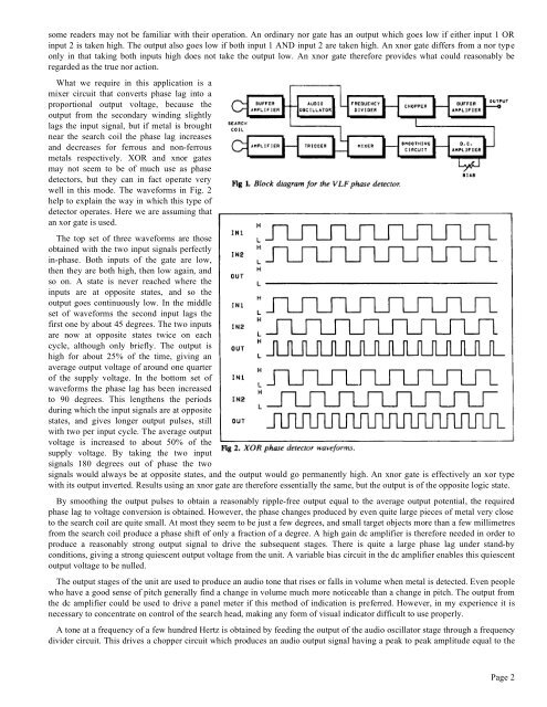
well in this mode. The waveforms in Fig. 2<br />
help to explain the way in which this type of<br />
detector operates. Here we are assuming that<br />
an xor gate is used.<br />
The top set of three waveforms are those<br />
obtained with the two input signals perfectly<br />
in-phase. Both inputs of the gate are low,<br />
then they are both high, then low again, and<br />
so on. A state is never reached where the<br />
inputs are at opposite states, and so the<br />
output goes continuously low. In the middle<br />
set of waveforms the second input lags the<br />
first one by about 45 degrees. The two inputs<br />
are now at opposite states twice on each<br />
cycle, although only briefly. The output is<br />
high for about 25% of the time, giving an<br />
average output voltage of around one quarter<br />
of the supply voltage. In the bottom set of<br />
waveforms the phase lag has been increased<br />
to 90 degrees. This lengthens the periods<br />
during which the input signals are at opposite<br />
states, and gives longer output pulses, still<br />
with two per input cycle. The average output<br />
voltage is increased to about 50% of the<br />
supply voltage. By taking the two input<br />
signals 180 degrees out of phase the two<br />
signals would always be at opposite states, and the output would go permanently high. An xnor gate is effectively an xor type<br />
with its output inverted. Results using an xnor gate are therefore essentially the same, but the output is of the opposite logic state.<br />
By smoothing the output pulses to obtain a reasonably ripple-free output equal to the average output potential, the required<br />
phase lag to voltage conversion is obtained. However, the phase changes produced by even quite large pieces of metal very close<br />
to the search coil are quite small. At most they seem to be just a few degrees, and small target objects more than a few millimetres<br />
from the search coil produce a phase shift of only a fraction of a degree. A high gain dc amplifier is therefore needed in order to<br />
produce a reasonably strong output signal to drive the subsequent stages. There is quite a large phase lag under stand-by<br />
conditions, giving a strong quiescent output voltage from the unit. A variable bias circuit in the dc amplifier enables this quiescent<br />
output voltage to be nulled.<br />
The output stages of the unit are used to produce an audio tone that rises or falls in volume when metal is detected. Even people<br />
who have a good sense of pitch generally find a change in volume much more noticeable than a change in pitch. The output from<br />
the dc amplifier could be used to drive a panel meter if this method of indication is preferred. However, in my experience it is<br />
necessary to concentrate on control of the search head, making any form of visual indicator difficult to use properly.<br />
A tone at a frequency of a few hundred Hertz is obtained by feeding the output of the audio oscillator stage through a frequency<br />
divider circuit. This drives a chopper circuit which produces an audio output signal having a peak to peak amplitude equal to the<br />
Page 2