
You also want an ePaper? Increase the reach of your titles
YUMPU automatically turns print PDFs into web optimized ePapers that Google loves.
great deal of use it would probably be better to opt for higher capacity batteries, such as two sets of six HP7 size cells in plastic<br />
holders.<br />
CIRCUIT BOARD<br />
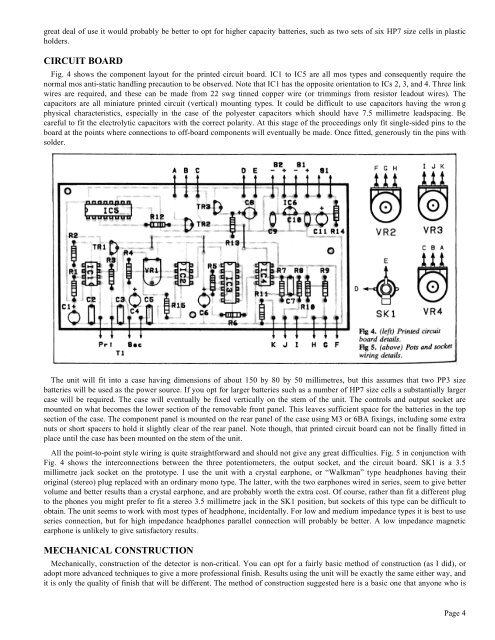
Fig. 4 shows the component layout for the printed circuit board. IC1 to IC5 are all mos types and consequently require the<br />
normal mos anti-static handling precaution to be observed. Note that IC1 has the opposite orientation to ICs 2, 3, and 4. Three link<br />
wires are required, and these can be made from 22 swg tinned copper wire (or trimmings from resistor leadout wires). The<br />
capacitors are all miniature printed circuit (vertical) mounting types. It could be difficult to use capacitors having the wron g<br />
physical characteristics, especially in the case of the polyester capacitors which should have 7.5 millimetre leadspacing. Be<br />
careful to fit the electrolytic capacitors with the correct polarity. At this stage of the proceedings only fit single-sided pins to the<br />
board at the points where connections to off-board components will eventually be made. Once fitted, generously tin the pins with<br />
solder.<br />
The unit will fit into a case having dimensions of about 150 by 80 by 50 millimetres, but this assumes that two PP3 size<br />
batteries will be used as the power source. If you opt for larger batteries such as a number of HP7 size cells a substantially larger<br />
case will be required. The case will eventually be fixed vertically on the stem of the unit. The controls and output socket are<br />
mounted on what becomes the lower section of the removable front panel. This leaves sufficient space for the batteries in the top<br />
section of the case. The component panel is mounted on the rear panel of the case using M3 or 6BA fixings, including some extra<br />
nuts or short spacers to hold it slightly clear of the rear panel. Note though, that printed circuit board can not be finally fitted in<br />
place until the case has been mounted on the stem of the unit.<br />
All the point-to-point style wiring is quite straightforward and should not give any great difficulties. Fig. 5 in conjunction with<br />
Fig. 4 shows the interconnections between the three potentiometers, the output socket, and the circuit board. SK1 is a 3.5<br />
millimetre jack socket on the prototype. I use the unit with a crystal earphone, or “Walkman” type headphones having their<br />
original (stereo) plug replaced with an ordinary mono type. The latter, with the two earphones wired in series, seem to give better<br />
volume and better results than a crystal earphone, and are probably worth the extra cost. Of course, rather than fit a different plug<br />
to the phones you might prefer to fit a stereo 3.5 millimetre jack in the SK1 position, but sockets of this type can be difficult to<br />
obtain. The unit seems to work with most types of headphone, incidentally. For low and medium impedance types it is best to use<br />
series connection, but for high impedance headphones parallel connection will probably be better. A low impedance magnetic<br />
earphone is unlikely to give satisfactory results.<br />
MECHANICAL CONSTRUCTION<br />
Mechanically, construction of the detector is non-critical. You can opt for a fairly basic method of construction (as I did), or<br />
adopt more advanced techniques to give a more professional finish. Results using the unit will be exactly the same either way, and<br />
it is only the quality of finish that will be different. The method of construction suggested here is a basic one that anyone who is<br />
Page 4