kota-kun & super-eflex (pdf 3825kb
kota-kun & super-eflex (pdf 3825kb
kota-kun & super-eflex (pdf 3825kb

You also want an ePaper? Increase the reach of your titles
YUMPU automatically turns print PDFs into web optimized ePapers that Google loves.
Underground Cable Installation<br />
KOTA-KUN & SUPER-EFLEX
1<br />
100% reuse rate for plastics:<br />
R-PP, PP, etc.<br />
Certification number: 01118065<br />
Awarded an encouraging prize from the Chairman of the Japan Electrical Construction Association<br />
Inc. at the products contest in the Electrical Construction Equipment and Materials Fair 2000.<br />
Registered in the New Technology Information System (NETIS) sponsored by the Ministry of Land,<br />
Infrastructure and Transport. Registration number is KT-990542.<br />
NKOTA-KUN<br />
FURUKAWA FK SYSTEM<br />
MULTI-HOLE PIPE OF<br />
S Y N T H E T I C R E S I
A NEW MULTI-HOLE PIPE OF UNIT-TYPE PURSUING<br />
WORK LABORSAVING AND COST REDUCTION<br />
FURUKAWA FK SYSTEM<br />
RESINKOTA-KUN<br />
MULTI-HOLE PIPE OF<br />
SYNTHETIC<br />
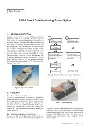
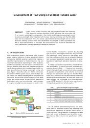
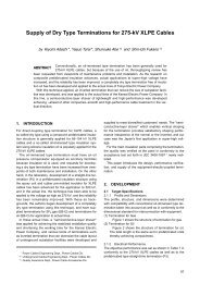
The information box project, the so-called<br />
C·C·Box Project, is being promoted by<br />
the Ministry of Land, Infrastructure and<br />
Transport, aimed at “promotion of underground<br />
laying of electric cables” as well as<br />
“early realization of advanced information<br />
society.” To respond to such demands of<br />
the times, Furukawa Electric has developed<br />
a multi-hole pipe of synthetic resin as a<br />
cable duct material using recycled plastics.<br />
We hope the customer will make use of our<br />
materials system for underground cable<br />
laying that we have developed in pursuit of<br />
work laborsaving, shortening of work periods<br />
and cost reduction.<br />
■ FEATURES<br />
● Excellent Withstand Load<br />
• Shallow burial method is possible.<br />
• Withstand load of the T25 class is provided<br />
when buried at 20cm beneath a<br />
roadway.<br />
• Stress at the joint is dispersed due to<br />
stacking in a staggered configuration.<br />
Crossing across the roadway of a national road<br />
● Compact Size and Excellent Impact<br />
Resistance<br />
• Excavation volume is minimized.<br />
• Produced soil can be used for backfilling.<br />
● Excellent Workability<br />
• Assembly work on site is<br />
simple.<br />
• Heavy machinery is not necessary<br />
due to the lightweight.<br />
• Multi-line, multi-tier laying is<br />
easy.<br />
• Jointing work of inner tube is<br />
not necessary.<br />
Backfilling with produced soil Long, continuous laying<br />
● Easy Line Feeding<br />
• Long, continuous cable feeding is possible.<br />
• Intervals between manholes and/or handholes<br />
can be lengthened.<br />
Laying work without using heavy machinery<br />
● Use of Recycled Plastics<br />
• Global environment conservation is promoted.<br />
• Effective use of resources.<br />
2
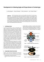
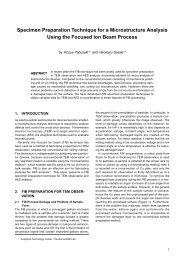
■ STANDARD INSTALLATION METHOD<br />
Excavate the route according to the design, and pack the soil floor to remove irregularities.<br />
● Installation Procedure<br />
1) Laying of the bottom tier of structure unit. 2) Laying of inner pipes.<br />
Try to use longer inner pipes as<br />
much as possible.<br />
50cm<br />
4) Repeat the procedures 2) and 3) as required,<br />
and lastly cover the top with the lids.<br />
● Processing of Manhole Wall<br />
1. ToughBosui (refer to page 6) can be<br />
used at the manhole walls to carry<br />
out both fixing and waterproofing<br />
simultaneously, making the duct system<br />
ready for backfilling.<br />
2. The structure unit should partly enter<br />
the manhole wall before mortar is<br />
applied to fill the gap, so as to make<br />
the duct system more resistant<br />
against shear loads due to possible<br />
uneven settlement, earthquake, etc.<br />
Manhole wall Manhole wall<br />
KOTA-KUN ToughBosui<br />
KOTA-KUN<br />
Mortar filling<br />
50cm<br />
1m<br />
3) Laying of the second tier of structure unit.<br />
Offset the lengthwise position by a half pitch<br />
from the bottom tier.<br />
5) When the whole assembly is completed,<br />
fix the assembly by using two insertion pins per<br />
structure unit at diagonal positions.<br />
Note: If length differences are generated in the inner pipes,<br />
cut the ends at the wall surface of the manholes to<br />
adjust them.<br />
3. When a holder plate having a suitable<br />
number of holes for inner pipes is set<br />
up at the inside of the wall, multi-tier,<br />
multi-line duct laying can be carried<br />
out speedily.<br />
Manhole wall<br />
Additional concrete casting<br />
KOTA-KUN<br />
4
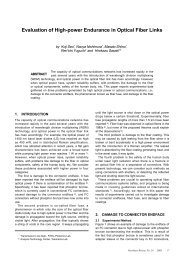
An example of installation<br />
work to cross a national road<br />
with busy traffic. Backfilling<br />
by using the produced soil<br />
and minimizing the excavation<br />
volume enable a shortperiod<br />
laying work.<br />
Due to the route straightness compared with conventional<br />
ducts, inner pipes can be smoothly fed through.<br />
5<br />
PRACTICAL INSTALLATION EXAMPLES OF KOTA-KUN<br />
Example of Road Crossing<br />
Example of Long-Length Installation<br />
It is possible to minimize<br />
the number of pipe<br />
joints by using inner<br />
pipes of long-length.<br />
Example of Installation at River Terrace Example of Detouring around Obstacles<br />
Example of Laying at Dam Site<br />
The duct system is applicable to concrete casting sites.<br />
By offsetting the<br />
position of the structure<br />
units, obstacles<br />
can be detoured in the<br />
directions either horizontal<br />
or vertical.<br />
Example of Information Box Installation<br />
■ Making a detour over an obstacle<br />
■ At a bridge site ■ Underground installation crossing a road ■ Shallow burial underneath a road<br />
■ Making a horizontal<br />
detour around an<br />
obstacle
Compression Strength<br />
Distributed live load L for T25 loading<br />
1. Distributed load for a burying depth of<br />
40cm or lower is expressed by the following<br />
equation.<br />
L=<br />
PERFORMANCE OF KOTA-KUN<br />
KOTA-KUN has a sufficient compression strength against the T25 loads enabling<br />
shallow burying without using concrete reinforcement.<br />
P<br />
(2H+a)·(2H+b2)<br />
3. Distributed load for cases where the burying<br />
depth exceeds 55cm and loads from<br />
adjacent axles overlap is expressed by the<br />
following equation.<br />
4P<br />
L=<br />
(2H+a)·W<br />
where: a is the ground contact length of a wheel.<br />
Impact Resistance<br />
Chemical Resistance<br />
Earthquake Resistance<br />
Compression test of KOTA-KUN has<br />
been carried out in compliance with<br />
the Design Guidelines for Common<br />
Cable Tunnel, whereby the T25<br />
load is calculated, and is multiplied<br />
with a safety factor of three.<br />
H≤40cm<br />
40cm55cm<br />
● Load calculation in compliance with the Design Guidelines<br />
for Common Cable Tunnel<br />
Dead load<br />
Material Load per 1-m depth (N/cm2 )<br />
Concrete 2.30<br />
Asphalt 2.25<br />
Crushed stone 2.06<br />
Backfilling sand 1.86<br />
Type Impact coefficient<br />
Roadway<br />
Covered depth less than 1m<br />
Covered depth 1m or more<br />
0.4<br />
0.3<br />
Sidewalk (considering vehicles) 0.1<br />
● Results of compression tests for φ80 × two lines<br />
Burying<br />
depth<br />
(cm)<br />
Total load<br />
(N/cm 2 )<br />
Compression load<br />
(safety factor: 3)<br />
(N/cm 2 )<br />
Deformation ratio of inner dia.<br />
of inner pipe (%)<br />
Temperature:<br />
20°C<br />
Temperature:<br />
60°C<br />
20 13.0 39.1 0 —<br />
25 10.3 30.9 0 —<br />
30 8.3 25.0 0 —<br />
40 6.0 17.9 0 —<br />
50 5.0 15.3 0 0<br />
55 4.9 14.7 0 0<br />
56 8.6 25.9 0 0<br />
60 8.2 24.7 0 0<br />
6
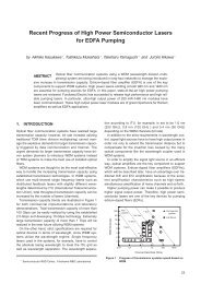
SUPER-EFLEX<br />
7
DUCT OF THE NEW ERA FOR UNDERGROUND BURYING OF<br />
HIGH-VOLTAGE CABLES<br />
REINFORCED FLEXIBLE PROTECTIVE PIPE OF SYNTHETIC RESIN<br />
SUPER-EFLEX<br />
Cable duct in compliance with JIS C 3653<br />
SUPER-EFLEX, a reinforced flexible<br />
protective pipe of synthetic resin, can<br />
solve diversified problems posed by the<br />
high-voltage cable works in urban areas<br />
taking advantage of its high strength, flexibility<br />
and corrosion resistance. SUPER-<br />
EFLEX of Furukawa Electric is now highlighted<br />
as a protective pipe of the new era<br />
for underground burying of high-voltage<br />
cables. It is made heat-resistant, impactresistant<br />
rigid polyvinyl chloride, and is<br />
provided with flame resistance in compliance<br />
with Appendix 1 of JIS C 3653.<br />
■ FEATURES<br />
● Excellent Mechanical Strength<br />
Due to its corrugated structure, the compression<br />
strength is <strong>super</strong>ior to that of<br />
EFLEX.<br />
● Excellent Heat Resistance<br />
A sufficient strength as underground duct<br />
is provided with against temperature rises<br />
due to heat radiation from high-voltage<br />
cables.<br />
● Electrical Characteristics<br />
Its electrical insulation is excellent.<br />
● Excellent Corrosion Resistance<br />
It is sufficiently resistant against chemicals<br />
such as acids and alkalis as well as<br />
other corrosive substances, raising no<br />
concerns about corrosion.<br />
● Lightweight<br />
Its lightweight in comparison to steel<br />
pipes makes transportation and laying<br />
easy.<br />
● Excellent Feed-through Property<br />
Due to its corrugated structure with<br />
smooth inner surface, cables can be<br />
easily fed through with a small friction.<br />
Accordingly, manhole intervals can be<br />
lengthened.<br />
● Excellent Installation Property<br />
Due to its lightweight, long continuous<br />
length and flexibility, laying work can be<br />
done easily and efficiently, and work periods<br />
can be shortened.<br />
● Flame Resistance<br />
In terms of flame resistance, it is equivalent<br />
to the flame resistant pipe with selfextinguishing<br />
property specified in the<br />
Clauses 139 and 140 of the Interpretation<br />
of Technical Standards for Electric<br />
Facilities of Japan, so that SUPER-EFLEX<br />
can be laid without allowing for spacing<br />
in between.<br />
8
9<br />
SUPER-EFLEX<br />
SFP-<br />
Item<br />
Inner dia. Outer dia. Nominal mass Standard<br />
Product No.<br />
(approx. mm) (approx. mm) (approx. kg/m) length (m)<br />
SFP-80 83 107 1.8 50<br />
SFP-100 103 134 2.5 20<br />
SFP-130 132 171 4.0 20<br />
SFP-150 150 193 4.8 20<br />
SFP-200 202 258 8.0 10<br />
STRAIGHT JOINT<br />
SFS-C C type<br />
Photograph of SFS-100C<br />
SUPER-EFLEX is a corrugated pipe<br />
with high, independent corrugations offering<br />
a high strength and high flexibility.<br />
Five sizes of φ80, φ100, φ130, φ150 and<br />
φ200 are available.<br />
This is used for mutual jointing of SUPER-EFLEX.<br />
Attachment of gasket Insertion of socket Fixing of O ring<br />
SFS-S Adhesion Type<br />
Photograph of SFS-100S<br />
Product No.<br />
Inner dia. D<br />
(approx. mm)<br />
Length L<br />
(approx. mm)<br />
SFS-80S 108 250<br />
SFS-100S 137 270<br />
SFS-130S 174 390<br />
SFS-150S 198 313<br />
SFS-200S 263 345<br />
Product No.<br />
D1<br />
(approx. mm)<br />
D<br />
D2<br />
(approx. mm)<br />
L<br />
Outer dia.<br />
Inner dia.<br />
This is a sleeve joint for mutual jointing of SUPER-<br />
EFLEX using adhesive for PVC pipes.<br />
D2<br />
L<br />
Pilot wire<br />
Notes<br />
• Can not be used for exposed piping outdoors.<br />
• Use a cover sheet when storing the products outdoors.<br />
• Do not store the products outdoors for a long period.<br />
• Do not drop the products from an elevated place nor give a<br />
strong shock.<br />
L<br />
(approx. mm)<br />
SFS-80C 113 132 215<br />
SFS-100C 141 161 260<br />
SFS-130C 178 196 285<br />
SFS-150C 200 220 300<br />
D1
SFS- Mechanical Type<br />
JOINT FOR DISSIMILAR PIPES<br />
SFT-M- Mechanical Type<br />
Photograph of SFT-100M-1<br />
Note: The end of SUPER-EFLEX should be cut<br />
perpendicularly at the peak of a corrugation.<br />
This is used for mutual jointing of<br />
SUPER-EFLEX.<br />
This is a mechanical joint for jointing<br />
SUPER-EFLEX with either steel pipe,<br />
cable conduit, or PVC pipe.<br />
SFT-E- Epoxy Adhesion Type (for Steel Pipe)<br />
Photograph of SFT-100E-1<br />
✽ Epoxy adhesive is included in a joint set.<br />
Product No.<br />
Outer dia. D<br />
(approx. mm)<br />
Length L<br />
(approx. mm)<br />
SFS-80 109 53<br />
SFS-100 136 61<br />
SFS-130 173 72<br />
SFS-150 195 88<br />
SFS-200 261 103<br />
This is a sleeve joint for jointing SUPER-<br />
EFLEX with steel pipes using epoxy adhesive.<br />
D<br />
Joint cover<br />
(material: stainless steel)<br />
L<br />
Rubber gasket<br />
Main body<br />
Note: The end of SUPER-EFLEX should be cut<br />
perpendicularly at the peak of a corrugation.<br />
D1<br />
Sleeve<br />
Cut ring<br />
SR gasket<br />
Collar<br />
Rubber gasket<br />
Joint cover<br />
Different pipe<br />
SUPER-EFLEX<br />
Nominal size or outer dia. (in parenthesis) of mating pipe<br />
SUPER-EFLEX Product No.<br />
Steel pipe (SGP)<br />
Cable conduit<br />
Heavy walled, with lining Heavy walled<br />
PVC pipe (VP) HIT pipe HIVP*<br />
φ100 SFT-100M-1 100 (114.3) 104 (114.6) 104 (113.4) 100 (114) 100 (114) —<br />
SFT-150M-1 150 (165.2) — — 150 (165) — —<br />
φ150 SFT-150M-2 125 (139.8) — — 125 (140) — —<br />
SFT-150M-4 — — — — 150 (170.5) 150 (170.5)<br />
✽ The same nominal size may include different actual sizes. Confirm the actual size.<br />
* For power cables, orange colored.<br />
L<br />
SUPER-EFLEX side Steel pipe side<br />
SUPER-EFLEX Product No.<br />
D1<br />
D2<br />
D3<br />
1<br />
2<br />
L<br />
(approx. mm) (approx. mm) (approx. mm) (approx. mm) (approx. mm) (approx. mm)<br />
Nominal size or outer dia. (in parenthesis)<br />
of mating pipe<br />
Steel pipe (SGP)<br />
φ100 SFT-100E-1 136 100 117 154 160 372 100 (114.3)<br />
φ150 SFT-150E-2 197 190 219 216 200 484 200 (216.3)<br />
✽ The same nominal size may include different actual sizes. Confirm the actual size.<br />
1<br />
D2<br />
2<br />
D3<br />
10
11<br />
SFT-S- Polyvinyl Chloride Adhesion Type (for PVC Pipe)<br />
Photograph of SFT-100S-1<br />
SUPER-EFLEX Product No.<br />
SFT-- Putty Type<br />
<br />
Photograph of SFT-80-1<br />
<br />
D1<br />
(approx. mm)<br />
<br />
<br />
This is a sleeve joint for jointing SUPER-<br />
EFLEX with PVC pipes using polyvinyl<br />
chloride adhesive.<br />
D2<br />
(approx. mm)<br />
D3<br />
(approx. mm)<br />
1<br />
(approx. mm)<br />
D1<br />
L<br />
SUPER-EFLEX side Steel pipe side<br />
This is a sleeve joint for jointing SUPER-EFLEX with dissimilar pipes using<br />
epoxy putty. Specify the type and size of the dissimilar pipe when ordering.<br />
Sleeve joint<br />
Epoxy putty<br />
EFLEX VUL-CO tape<br />
PVC tape<br />
2<br />
(approx. mm)<br />
L<br />
(approx. mm)<br />
1<br />
D2<br />
Nominal size or outer dia. (in<br />
parenthesis) of mating pipe<br />
PVC pipe (VP) HIT pipe<br />
φ100 SFT-100S-1 136 100 115 154 84 235 100 (114) 100 (114)<br />
φ150<br />
SFT-150S-1 197 150 166 221 132 430 150 (165) —<br />
SFT-150S-2 197 160 172 221 132 430 — 150 (170.5)<br />
φ200 SFT-200S-1 263 200 218 222 200 520 200 (216) —<br />
✽ The same nominal size may include different actual sizes. Confirm the actual size.<br />
SUPER-EFLEX<br />
φ80<br />
φ100<br />
φ130<br />
φ150<br />
φ200<br />
Product No.<br />
(approx. inner<br />
dia. of dissimilar<br />
pipe side in mm)<br />
Steel pipe Cable conduit PVC pipe Water-proof<br />
(SGP) Heavy walled HIVP VP cast iron pipe<br />
Nominal size or outer dia. (in parenthesis) of mating pipe<br />
Asbestos<br />
pipe (ACP)<br />
Polycon<br />
pipe (PFP)<br />
High-strength<br />
corrugated<br />
pipe<br />
EFLEX<br />
2<br />
Hume pipe<br />
(HP)<br />
D3<br />
FRP pipe<br />
SFT-80-1 ( 95) 80 (89.1) 82 (87.9) 75 (89) 75 (89) 80 (86.3)<br />
SFT-80-2 (108) 75 (99) 80 (102)<br />
SFT-80-3 (120) 75 (111)<br />
SFT-80-4 (100) 75 (95) 75 (95)<br />
SFT-80-5 ( 70) 50(65)<br />
SFT-100-1 (125) 100 (114.3) 104 (113.4) 100 (114) 100 (114)<br />
SFT-100-2 (130) 100 (124) 100 (122) 100 (120)<br />
SFT-100-3 (155) 100 (145) 100 (150)<br />
SFT-100-4 (140) 100 (130)<br />
SFT-100-5 (110) 100 (106.3)<br />
SFT-130-1 (150) 125 (139.8) 125 (140) 125 (145)<br />
SFT-130-2 (160) 130 (147.5) 130 (154) 130 (155) 100 (150)<br />
SFT-130-3 (185) 130 (177) 130 (175)<br />
SFT-130-4 (170) 125 (160)<br />
SFT-130-5 (140) 130 (136.3)<br />
SFT-150-1 (175) 150 (165.2) 150 (165)<br />
SFT-150-2 (185) 150 (174) 150 (177) 150 (174)<br />
SFT-150-3 (215) 150 (202) 150 (202)<br />
SFT-150-4 (200) 150 (189)<br />
SFT-200-1 (225) 200 (216.3) 200 (216)<br />
SFT-200-2 (240) 200 (224) 200 (231) 200 (230)<br />
SFT-200-3 (268) 200 (258)<br />
SFT-200-4 (260) 200 (253) 200 (254)<br />
Ask for information on the joints for dissimilar pipes not listed here. Delivery time is two to three weeks.<br />
✽ The same nominal size may include different actual sizes. Confirm the actual size.
Bell-mouth (Drive-in type)<br />
SFM-<br />
Photograph of SFM-100<br />
Product No. D (approx. mm) d (approx. mm) L (approx. mm)<br />
SFM-80 110 75 85<br />
SFM-100 144 93 100<br />
SFM-130 186 123 130<br />
SFM-150 200 140 150<br />
SFM-200 280 191 200<br />
Long Bell Mouth (Adhesion type)<br />
SFM-LR<br />
SFM-LS<br />
Photograph of SFM-100LR<br />
Cap for Spare Pipe<br />
SFC- Cap for Spare Pipe<br />
This is used on the pipe end at manholes<br />
or hand holes for the purpose of<br />
damage protection during cable feed-in<br />
as well as appearance improvement.<br />
This is used for attachment of pipes<br />
on the manholes or hand holes. Use<br />
the LS type (surface coated with sand)<br />
for φ200mm pipe. The L type of 500mm<br />
in length (surface coated with sand,<br />
made-to-order) and the LS type for<br />
φ80mm~φ150mm are also available.<br />
Product No. d1 (approx. mm) d2 (approx. mm) D (approx. mm) L (approx. mm)<br />
SFM-80LR 108 83 117 350<br />
SFM-100LR 137 104 148 350<br />
SFM-130LR 174 134 179 350<br />
SFM-150LR 198 154 208 350<br />
SFM-200LS 263 202 263 350<br />
Avoid adherence of org ,<br />
attention must be paid to sealing materials and primers because these often contain organic solvents.<br />
Photograph of SFC-100<br />
This is a cap for spare pipes to prevent<br />
entry of sand and dust. This can be used<br />
as a bell mouth if its end is cut off.<br />
Product No. D (approx. mm) d (approx. mm) (approx. mm) L (approx. mm)<br />
SFC-80 115 75 85 125<br />
SFC-100 150 93 100 140<br />
SFC-130 190 123 135 170<br />
SFC-150 205 140 150 200<br />
SFC-200 295 191 200 260<br />
Wall surface<br />
Mortar<br />
Outside Inside<br />
SUPER-EFLEX<br />
Wall surface<br />
Mortar<br />
D<br />
SUPER-EFLEX Mortar<br />
Long bell<br />
mouth<br />
d1<br />
Different shape for φ 200<br />
SUPER-EFLEX Mortar<br />
Outside Inside<br />
D<br />
L<br />
Outside<br />
L<br />
Cut position<br />
L<br />
d<br />
Bell mouth<br />
Wall surface<br />
Cap for spare pipe<br />
d<br />
Inside<br />
d2<br />
D<br />
12
13<br />
Waterproof Plug<br />
FW-<br />
Photograph of FW-125A<br />
Waterproofing Materials for Pipe End<br />
SFB- (for single line laying)<br />
SFFB- (for multi line laying)<br />
Photograph of SFB-100<br />
Product No. D1<br />
Single line Multi line (approx. mm)<br />
Spacer for SUPER-EFLEX<br />
FVPS-<br />
Photograph of FVPS-100<br />
D2<br />
(approx. mm)<br />
This is used to prevent entry of water and<br />
foreign materials into spare pipes.<br />
Product<br />
No.<br />
Applicable bell mouth Dimensions<br />
Bell<br />
mouth<br />
After cables are fed into SUPER-EFLEX,<br />
the pipe ends have to be sealed using<br />
these materials against entry of earth and<br />
water. Specify the material set for multi<br />
lines in case the cable used is triplex type<br />
or multi cables en bloc.<br />
This spacer allows for multi-tier laying<br />
of pipes without undue slackening.<br />
It enables the same en bloc laying and<br />
en bloc backfilling as for straight pipes,<br />
effectively shortening the installation time<br />
especially in multi-tier laying.<br />
1m<br />
2m<br />
1m<br />
Long bell<br />
mouth<br />
D1<br />
(approx.<br />
mm)<br />
● Spacer spacing for three-line laying<br />
D2<br />
(approx.<br />
mm)<br />
FW-80A SFM-80 — 86 70<br />
FW-80B — SFM-80LR 86 78<br />
FW-100A SFM-100 — 125 88<br />
FW-125A — SFM-100LR 125 98<br />
FW-130A SFM-130 — 145 122<br />
FW-150A SFM-150 SFM-130LR 145 128<br />
FW-150B — SFM-150LR 180 148<br />
FW-200A — SFM-200LS 210 198<br />
D2<br />
For long bell mouth φ100 and φ150<br />
D1<br />
Slightly different shape for other sizes<br />
Before insertion, plump the rubber gasket part close to the inner diameter of the bell mouth.<br />
D3<br />
(approx. mm)<br />
L<br />
(approx. mm)<br />
SFB-80 SFFB-80 105 69 20 118<br />
SFB-100 SFFB-100 140 80 30 120<br />
SFB-130 SFFB-130 170 104 45 150<br />
SFB-150 SFFB-150 195 130 70 160<br />
SFB-200 SFFB-200 240 170 90 165<br />
Product No. W (approx. mm)<br />
FVPS-100 395<br />
FVPS-130 426<br />
FVPS-150 447<br />
D1<br />
100mm for φ100<br />
pipe<br />
or slimmer<br />
150mm for φ 130 pipe<br />
or larger<br />
D2<br />
(250)<br />
W<br />
L<br />
Cable<br />
EFLEX VUL-CO tape<br />
Sand prevention seal<br />
Waterproof compound or<br />
sealing tape<br />
SUPER-EFLEX<br />
Manhole or hand hole<br />
PVC tape<br />
The spacing is 1.5m for two-line laying. In case of<br />
three-line laying or more, the spacing between adjacent<br />
spacers should be 1m in a staggered configuration, but it<br />
should be not more than 2m on any single line.<br />
D3<br />
50
■ Installation Method of<br />
Spacer<br />
✽ Use the C-type straight joint.<br />
Distances between cross-sectional centers<br />
Pipe size A (approx. mm) B (approx. mm)<br />
φ100 250 137<br />
φ130 250 175<br />
φ150 250 198 Fit the spacer on to the<br />
pipe.<br />
PERFORMANCE OF SUPER-EFLEX<br />
■ Material Properties<br />
Material properties of heat-resistant,<br />
impact-resistant polyvinyl chloride are<br />
shown here.<br />
■ Chemical Resistance<br />
■ Product Performance<br />
1. Compression Performance<br />
Deformation ratio of the pipe under a<br />
compression load of 122.5kN/m 2 (12.5t/<br />
m 2 ) is shown in the Table.<br />
300<br />
500<br />
Product No. Test load (N) Deformation ratio<br />
SFP-80 3920 {400kgf} ≤ 2.5%<br />
SFP-100 5586 {570kgf} ≤ 2.5%<br />
SFP-130 6272 {640kgf} ≤ 2.5%<br />
SFP-150 7154 {730kgf} ≤ 2.5%<br />
SFP-200 9212 {940kgf} ≤ 2.5%<br />
2. Tensile Strength<br />
Tensile strength of the pipe under axial<br />
tension is shown in the Table.<br />
Product No. Tensile strength (N)<br />
SFP-80 ≥ 2940 {300kgf}<br />
SFP-100 ≥ 3920 {400kgf}<br />
SFP-130 ≥ 4900 {500kgf}<br />
SFP-150 ≥ 5880 {600kgf}<br />
SFP-200 ≥ 7840 {800kgf}<br />
3. Bending Performance<br />
Bending moment needed to bend a pipe<br />
to 5DR x 90degree is shown in the Table,<br />
whereby the pipe is fixed on one end and<br />
the load is applied at a specified position<br />
as shown. (where: D is the inner diameter<br />
of pipe)<br />
P<br />
L<br />
5DR<br />
Test results<br />
Product No. Bending moment (approx. N·m)<br />
SFP-80 93 {9.5kgf·m}<br />
SFP-100 93 {9.5kgf·m}<br />
SFP-130 157 {16kgf·m}<br />
SFP-150 216 {22kgf·m}<br />
SFP-200 470 {48kgf·m}<br />
Set the upper pipe so that<br />
the spacer protrusion fit in<br />
the corrugation trough.<br />
4. Bendability<br />
No abnormalities are found when a pipe<br />
is bent three times in reversed directions<br />
around a bender frame having a radius<br />
of 5DR. (where: D is the inner diameter of<br />
pipe)<br />
5DR<br />
5. Flame Resistance (Self-extinguishing)<br />
When a half-cut pipe is fixed horizontally<br />
and a gas burner specified in JIS C 8430<br />
is used to burn the center, either the inner<br />
or the outer surface, it extinguishes by it<br />
self not later than 1min after the burner is<br />
taken away.<br />
6. Friction Coefficient<br />
0.35 or less.<br />
A<br />
B<br />
B<br />
Set the uppermost spacer<br />
to complete the laying.<br />
Item Physical property Test method<br />
Color Orange<br />
Specific gravity 1.43 Sink-Float method<br />
Tensile strength (N/mm2 ) 49.0 {5.0kgf/mm2 } JIS K 6742 15°C<br />
Bending strength (N/mm2 ) 68.6 {7.0kgf/mm2 } JIS K 6711 20°C 65%RH<br />
Flexural modulus (103N/mm2 ) 2.45 {2.5×10²kgf/mm2 } JIS K 6911 20°C 65%RH<br />
Charpy impact toughness (10-3J/mm2 ) 17.6 {18kgf·cm/cm2 } JIS K 7111 20°C<br />
Chemical<br />
Temperature (°C)<br />
20 40 60<br />
Chemical<br />
Temperature (°C)<br />
20 40 60<br />
Hydrochloric acid 35% Seawater <br />
Sulfuric acid 60% Formalin <br />
Nitric acid 70% Benzene <br />
Acetic acid, lower than 95% Acetone —<br />
Sodium hydrate Gasoline <br />
Ammonia water Ethanol <br />
: absolutely not corroded, : practically not corroded, : slightly corroded, : unusable<br />
Product No. L (mm)<br />
SFP-80 1<br />
SFP-100 1<br />
SFP-130 1.3<br />
SFP-150 1.5<br />
SFP-200 2<br />
Bunsen burner<br />
Specimen<br />
=Half-cut pipe of 0.3m in length<br />
14