HQ Studio Frame Manual for HQ Avante 08-09-11 ... - Handi Quilter
HQ Studio Frame Manual for HQ Avante 08-09-11 ... - Handi Quilter
HQ Studio Frame Manual for HQ Avante 08-09-11 ... - Handi Quilter

Create successful ePaper yourself
Turn your PDF publications into a flip-book with our unique Google optimized e-Paper software.
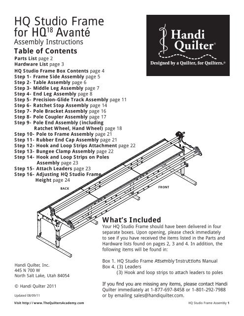
<strong>HQ</strong> <strong>Studio</strong> <strong>Frame</strong><br />
<strong>for</strong> <strong>HQ</strong> 18 Avanté<br />
Assembly Instructions<br />
Table of Contents<br />
Parts List page 2<br />
Hardware List page 3<br />
<strong>HQ</strong> <strong>Studio</strong> <strong>Frame</strong> Box Contents page 4<br />
Step 1- <strong>Frame</strong> Side Assembly page 5<br />
Step 2- Table Assembly page 6<br />
Step 3- Middle Leg Assembly page 7<br />
Step 4- End Leg Assembly page 8<br />
Step 5- Precision-Glide Track Assembly page <strong>11</strong><br />
Step 6- Ratchet Stop Assembly page 14<br />
Step 7- Pole Bracket Assembly page 16<br />
Step 8- Pole Coupler Assembly page 17<br />
Step 9- Pole End Assembly (including<br />
Ratchet Wheel, Hand Wheel) page 18<br />
Step 10- Pole to <strong>Frame</strong> Assembly page 21<br />
Step <strong>11</strong>- Rubber End Cap Assembly page 21<br />
Step 12- Hook and Loop Strips Attachment page 22<br />
Step 13- Bungee Clamp Assembly page 22<br />
Step 14- Hook and Loop Strips on Poles<br />
Assembly page 23<br />
Step 15- Attach Leaders page 23<br />
Step 16- Adjusting <strong>HQ</strong> <strong>Studio</strong> <strong>Frame</strong><br />
Height page 24<br />
BACK<br />
<strong>Handi</strong> <strong>Quilter</strong>, Inc.<br />
445 N 700 W<br />
North Salt Lake, Utah 84054<br />
© <strong>Handi</strong> <strong>Quilter</strong> 20<strong>11</strong><br />
Updated <strong>08</strong>/<strong>09</strong>/<strong>11</strong><br />
Visit http://www.The<strong>Quilter</strong>sAcademy.com<br />
MAIN PAGE<br />
FIG. <strong>11</strong>-1<br />
FIG, 12-1<br />
FIG. 13-1<br />
What’s Included<br />
Designed by a <strong>Quilter</strong>, <strong>for</strong> <strong>Quilter</strong>s. ®<br />
FRONT<br />
Your <strong>HQ</strong> <strong>Studio</strong> <strong>Frame</strong> should have been delivered in four<br />
separate boxes. Upon opening, please check immediately<br />
to see if you have received the items listed in the Parts and<br />
Hardware lists found on pages 2, 3 and 4. In addition, the<br />
following items will be found in:<br />
Box 1. <strong>HQ</strong> <strong>Studio</strong> <strong>Frame</strong> Assembly Instructions <strong>Manual</strong><br />
Box 4. (3) Leaders<br />
(3) Hook and loop strips to attach leaders to poles<br />
If you find you are missing any items, please contact <strong>Handi</strong><br />
<strong>Quilter</strong> immediately at 1-877-697-8458 or 1-801-292-7988<br />
or by emailing sales@handiquilter.com.<br />
<strong>HQ</strong> <strong>Studio</strong> <strong>Frame</strong> Assembly 1<br />
FIG. 4-1
RONT<br />
QF<strong>09</strong>318-410<br />
BATTING BAR BRACKET<br />
FIG. 6-2<br />
Fig. 6-1 <strong>HQ</strong> <strong>Studio</strong> <strong>Frame</strong> Parts List<br />
QF<strong>09</strong>318-730<br />
POLE ASSY<br />
QF<strong>09</strong>318-05<br />
TABLE SPLICE BRACE<br />
Right <strong>Frame</strong><br />
Side Back (1)<br />
QF<strong>09</strong>318-412<br />
QF<strong>09</strong>318-700 RIGHT FRAME SIDE, BACK<br />
Box 3<br />
POLE ASSY<br />
QF<strong>09</strong>318-512<br />
LEFT FRAME SIDE, BACK<br />
MIDDLE LEG STAND<br />
QF<strong>09</strong>318-740<br />
POLE ASSY<br />
Right <strong>Frame</strong><br />
Side Front (1)<br />
Box 3<br />
QF<strong>09</strong>318-4<strong>11</strong><br />
RIGHT SIDE FRAME, FRONT<br />
Left <strong>Frame</strong> Left <strong>Frame</strong><br />
Side Back (1) Side Front (1)<br />
Box 3<br />
Hook and Loop<br />
Strip (2)<br />
<strong>Frame</strong> Side<br />
Coupler (2)<br />
Box 3<br />
TRACK SUPPORT<br />
QF<strong>09</strong>318-01<br />
COUPLER<br />
QF<strong>09</strong>318-410<br />
BATTING BAR BRACKET<br />
Bungee Clamp (4)<br />
Box 3<br />
Box 3<br />
QF<strong>09</strong>318-5<strong>11</strong> QF<strong>09</strong>318-510<br />
BATTING BAR BRACKET<br />
LEFT SIDE FRAME, FRONT<br />
Fig. 5-5<br />
Bottom minus screws<br />
QF<strong>09</strong>318-730<br />
POLE ASSY<br />
QF<strong>09</strong>318-410<br />
BATTING BAR BRACKET<br />
Ten in Box 2 and five in Box 4<br />
(Note: 10’ frame has ten 4’ poles<br />
in Box 2 and five 2’ in Box 4)<br />
4’ Pole Section<br />
COUPLER<br />
Fig. 6-1<br />
QF<strong>09</strong>318-412<br />
RIGHT FRAME SIDE, BACK<br />
12FT BLACK PLASTIC TRACK<br />
Right Side Leg (1)<br />
2 <strong>HQ</strong> <strong>Studio</strong> <strong>Frame</strong> Assembly<br />
QF<strong>09</strong>318-400<br />
END LEG STAND, RIGHT<br />
QF<strong>09</strong>318-05<br />
QF<strong>09</strong>318-01<br />
Visit http://www.<strong>Handi</strong><strong>Quilter</strong>.com<br />
TABLE SPLICE BRACE<br />
COUPLER<br />
Box 3<br />
Fig. 6-1<br />
With table section: Four in Box 1 and two in Box 4<br />
12ft Plastic Track (4) (Black)<br />
Fig. 9-1 Fig. 9-2<br />
Fig. 8-1<br />
Fig. 9-4<br />
BAR BRACKET<br />
BATTING<br />
QF<strong>09</strong>318-510<br />
2’ Coupler (10)<br />
Fig. 9-3<br />
Box 2<br />
Box 3<br />
QF<strong>09</strong>318-740<br />
POLE ASSY<br />
QF<strong>09</strong>318-4<strong>11</strong><br />
RIGHT SIDE FRAME, FRONT<br />
Track Support Section (6)<br />
TRACK SUPPORT<br />
Table Splice Brace (4)<br />
Box 3<br />
Fig. 5-5<br />
Bottom minus screws<br />
Table Section (3)<br />
2 in Box 1 and 1 in Box 4<br />
TABLE SECTION<br />
Fig. 9-1 Fig. 9-2<br />
Fig. 9-3<br />
TRACK SUPPORT<br />
Fig. 8-1<br />
FIG. 6-2<br />
Track Support<br />
Coupler (4)<br />
Box 3<br />
RIGHT POLE BRACKET<br />
MIDDLE LEG STAND<br />
COUPLER<br />
Left Side Leg (1)<br />
Box 3<br />
QF<strong>09</strong>318-500<br />
END LEG STAND, LEFT QF<strong>09</strong>318-400<br />
QF<strong>09</strong>318-05<br />
QF<strong>09</strong>31<br />
END LEG STAND, RIGHT<br />
TABLE SPLICE BRACE<br />
COU<br />
Plugged-Hole Pole Bracket (1)<br />
Box 1<br />
Middle Leg (2)<br />
FIG. 6-2<br />
12FT BLACK PLASTIC TRACK<br />
COUP<br />
Box 3<br />
Open-Hole Pole Bracket (1)<br />
Box 1
318-202<br />
TOP MOUNT<br />
-705<br />
EARING<br />
CONNECTOR BOLT<br />
Rubber End<br />
Cap<br />
(10)<br />
QF<strong>09</strong>318-103<br />
QF<strong>09</strong>318-720 QF<strong>09</strong>318-202<br />
Ratchet Stop<br />
QF<strong>09</strong>318-203 (3)<br />
18-720<br />
EEL 18-201 ASSY<br />
BUNGEE HOLDER BUNGEE HOLDER COVER<br />
SHORT BOLT RATCHET WHEEL<br />
QF<strong>09</strong>318-720 HAND WHEEL RATCHET ASSY STOP MOUNT<br />
OP 3 BUSHING HAND WHEEL ASSY<br />
CER<br />
RATCHET STOP<br />
Leveling Foot<br />
LEVELING (8) FOOT<br />
Visit http://www.The<strong>Quilter</strong>sAcademy.com<br />
M8 x 25mm<br />
Socket Button<br />
Head Cap<br />
Screw (SBHCS)<br />
(4)<br />
5mm Allen<br />
Wrench<br />
(1)<br />
4mm Allen<br />
QF<strong>09</strong>318-713Wrench<br />
(1)<br />
<strong>HQ</strong> <strong>Studio</strong> <strong>Frame</strong> Hardware List<br />
M8 x 16mm Socket<br />
Button Head Cap<br />
Screw (SBHCS)<br />
(64 total)<br />
QF<strong>09</strong>318-104<br />
QF<strong>09</strong>318-730<br />
QF<strong>09</strong>318-103<br />
QF<strong>09</strong>318-730 Ratchet-Stop<br />
QF<strong>09</strong>318-202<br />
QF<strong>09</strong>318-730<br />
QF<strong>09</strong>318-201<br />
QF<strong>09</strong>318-730<br />
SHORT BOLT RATCHET<br />
BUNGEE<br />
WHEEL<br />
HOLDER SPACER<br />
RATCHET M6 x 45mm<br />
SHORT BOLT RATCHET QF<strong>09</strong>318-204<br />
Mount QF<strong>09</strong>318-105<br />
STOP MOUNT<br />
RATCHET STOP WHEEL BUSHING<br />
CONNECTOR Connector<br />
(3)<br />
BOLT<br />
QF<strong>09</strong>318-205<br />
Screw<br />
RATCHET STOP HOLDER<br />
(3)<br />
M8 Lock<br />
Nut<br />
(4)<br />
M6 x 12mm<br />
Connector Screw<br />
(12 total)<br />
(8 in Box 1)<br />
LEVELING FOOT<br />
(4 in Box 3)<br />
3mm Allen<br />
Wrench<br />
(1)<br />
These parts found in Box #3<br />
M8 Flat Washer<br />
(4)<br />
QF<strong>09</strong>318-203 Ratchet-Stop<br />
QF<strong>09</strong>318-730 QF<strong>09</strong>318-204<br />
QF<strong>09</strong>318-201<br />
RATCHET Bushing STOP QF<strong>09</strong>318-106<br />
CONNECTOR BOLT<br />
(3)<br />
M5 x 8mm<br />
Socket Button<br />
Head Cap Screw<br />
(SBHCS)<br />
(24 total)<br />
<strong>09</strong>318-103<br />
QF<strong>09</strong>318-104<br />
QF<strong>09</strong>318-103<br />
QF<strong>09</strong>318-103<br />
GEE HOLDER<br />
QF<strong>09</strong>318-203<br />
QF<strong>09</strong>318-104<br />
BUNGEE HOLDER COVER<br />
QF<strong>09</strong>318-103<br />
QF<strong>09</strong>318-104<br />
QF<strong>09</strong>318-205<br />
BUNGEE HOLDER SPACER<br />
BUNGEE HOLDER<br />
Short Bolt Ratchet<br />
QF<strong>09</strong>318-103<br />
BUNGEE HOLDER RATCHET STOP<br />
BUNGEE HOLDER COVER<br />
BUNGEE HOLDER COVER<br />
RATCHET STOP HOLDER QF<strong>09</strong>318-203<br />
QF<strong>09</strong>318-730<br />
Wheel Assembly<br />
BUNGEE HOLDER SPACER<br />
Long Bolt Ratchet<br />
Pole End RATCHET STOP<br />
QF<strong>09</strong>318-720<br />
Hand Wheel<br />
QF<strong>09</strong>318-730<br />
(2)<br />
SHORT BOLT RATCHET WHEEL Wheel Assembly QF<strong>09</strong>318-730<br />
318-720<br />
QF<strong>09</strong>318-730<br />
Assembly<br />
HAND WHEEL ASSY Assembly<br />
SHORT BOLT RATCHET WHEEL<br />
QF<strong>09</strong>318-730(1)<br />
LONG BOLT RATCHET (7) WHEEL<br />
HEEL ASSY<br />
LONG BOLT RATCHET WHEEL<br />
QF<strong>09</strong>318-720 (1)<br />
F<strong>09</strong>318-203<br />
SHORT BOLT RATCHET WHEEL<br />
QF<strong>09</strong>318-205<br />
HAND WHEEL ASSY<br />
ATCHET STOP<br />
RATCHET STOP HOLDER<br />
LIP<br />
Hand Wheel Insert (1)<br />
QF<strong>09</strong>318-713<br />
May be preassembled<br />
with HAND Hand WHEEL Wheel. COLLAR<br />
17/13/16mm<br />
Wrench<br />
(1)<br />
LEVELING FOOT<br />
<strong>HQ</strong> <strong>Studio</strong> <strong>Frame</strong> Assembly 3<br />
Q<br />
BUNGEE<br />
Q<br />
LONG BO<br />
QF<strong>09</strong>318-202<br />
QF<strong>09</strong>318-105<br />
QF<strong>09</strong>318-205<br />
QF<strong>09</strong>318-<br />
LONG BOLT RATCHET QF<strong>09</strong>318-730 WHEEL LONG BOLT RATCHET WHEEL<br />
RATCHET Holder STOP HOLDER<br />
RATCHET RAIL BEARING STOP MOUNT SNAP<br />
RAIL LONG BEARING BOLT RATCHET SNAP WHEEL<br />
QF<strong>09</strong>318-105 RAIL BEARING QF<strong>09</strong>31 SN<br />
RATCHET STOP BUSHING RAIL BEARING SNAP COVER (3)<br />
Fig. 10-2 CONNECTO<br />
QF<strong>09</strong>318-106<br />
RAIL BEARING SNAP COVER<br />
QF<strong>09</strong>318-105<br />
Fig. 10-2<br />
QF<strong>09</strong>318-713<br />
QF<strong>09</strong>318-202<br />
QF<strong>09</strong>318-703<br />
QF<strong>09</strong>318-705<br />
QF<strong>09</strong>318-201<br />
HAND WHEEL COLLAR<br />
QF<strong>09</strong>318-204<br />
QF<strong>09</strong>318-105<br />
QF<strong>09</strong>318-106<br />
RATCHET STOP MOUNT<br />
QF<strong>09</strong>318-713<br />
OUTSIDE POLE END<br />
V-GROOVE BEARING<br />
QF<strong>09</strong>318-714<br />
QF<strong>09</strong>318-105 QF<strong>09</strong>318-713<br />
RATCHET STOP BUSHING<br />
CONNECTOR BOLT<br />
RAIL BEARING SNAP<br />
RAIL BEARING SNAP COVER<br />
LEVELIN<br />
<strong>09</strong>318-703<br />
QF<strong>09</strong>318-705<br />
HAND WHEEL COLLAR<br />
QF<strong>09</strong>318-703 STEEL SNAPPING QF<strong>09</strong>318-705<br />
BUTTON/LOCKING CLIP Fig. HAND 10-2 WHEEL COLL<br />
IDE POLE END QF<strong>09</strong>318-105V-GROOVE<br />
BEARING QF<strong>09</strong>318-106<br />
QF<strong>09</strong>318-714<br />
OUTSIDE POLE END<br />
V-GROOVE BEARING<br />
QF<strong>09</strong>318-105<br />
LEVELING FOOT<br />
RAIL BEARING SNAP<br />
RAIL BEARING SNAP COVER<br />
STEEL SNAPPING BUTTON/LOCKING CLIP<br />
QF<strong>09</strong>318-703<br />
OUTSIDE POLE END<br />
QF<strong>09</strong>318-714<br />
EL SNAPPING BUTTON/LOCKING CLIP<br />
QF<strong>09</strong>318-204<br />
QF<strong>09</strong>318-705<br />
V-GROOVE BEARING<br />
LEVELING FOOT<br />
QF<strong>09</strong>318-105<br />
RAIL BEARING SNAP<br />
QF<strong>09</strong>318-714<br />
STEEL SNAPPING BUTTON/LOCKING CLIP<br />
Fig. 10-2<br />
HAND WHEEL COLLAR<br />
QF<strong>09</strong>318-106<br />
RAIL BEARING SNAP COVER<br />
QF<strong>09</strong>318-714<br />
STEEL SNAPPING BUTTON/LOCKING CLIP<br />
QF<strong>09</strong>318-105<br />
Fig. 10-2<br />
Fig. 9-3<br />
Ratchet-Stop<br />
Fig. 9-2
<strong>HQ</strong> <strong>Studio</strong> <strong>Frame</strong> Box Contents<br />
Box<br />
No.<br />
1<br />
Parts<br />
Two 4-foot table sections with track supports (4) , M6 X 12mm Connector<br />
screw (8) and left and right pole brackets<br />
2 10 poles, 10 couplers<br />
3 All other parts (including plastic tracks)<br />
4<br />
Box<br />
No.<br />
4<br />
12' frame<br />
One 4-foot table section w/track supports (2), M6 X 12mm Connector<br />
screw (4), five 4-foot poles<br />
10' frame (Boxes 1, 2 & 3 same as 12-foot)<br />
Parts<br />
One 2-foot table section with track supports (2), M6 X 12mm Connector<br />
screw (4), five 2-foot poles<br />
4 <strong>HQ</strong> <strong>Studio</strong> <strong>Frame</strong> Assembly Visit http://www.<strong>Handi</strong><strong>Quilter</strong>.com
Step 1<br />
<strong>Frame</strong> Side Assembly<br />
Note: Assembly is easiest if all<br />
connections are finger-tightened first<br />
Fig. 2-1<br />
as instructed, while assembling the<br />
frame. Tighten with the wrench when<br />
instructed.<br />
Why is this important? If you tighten<br />
as you go, you may have trouble<br />
getting all the parts to align properly.<br />
Note: Make<br />
sure both height-<br />
adjustable<br />
legs are at<br />
their shortest<br />
setting be<strong>for</strong>e<br />
proceeding.<br />
Remember that<br />
the batting bar<br />
bracket needs to<br />
be on the outside<br />
of the leg.<br />
(Fig. 1-1)<br />
Visit http://www.The<strong>Quilter</strong>sAcademy.com<br />
QF<strong>09</strong>318-103<br />
BUNGEE HOLDER<br />
QF<strong>09</strong>318-201<br />
RATCHET STOP BUSHING<br />
QF<strong>09</strong>318-703<br />
OUTSIDE POLE END<br />
QF<strong>09</strong>318-104<br />
BUNGEE HOLDER COVER<br />
Step 1: <strong>Frame</strong> Side Assembly<br />
Parts needed<br />
1-Right Side Leg<br />
1-Left Side Leg<br />
1-Right <strong>Frame</strong> Side Front<br />
1-Left <strong>Frame</strong> Side Front<br />
1-Right <strong>Frame</strong> Side Back<br />
1-Left <strong>Frame</strong> Side Back<br />
4-Leveling Feet<br />
16-M8 x 16mm SBHCS<br />
M8 X 16 SBHCS X 4<br />
QF<strong>09</strong>318-202<br />
RATCHET STOP MOUNT<br />
QF<strong>09</strong>318-705<br />
V-GROOVE BEARING<br />
Tools Required<br />
5mm Allen Wrench (Provided)<br />
1-1: Screw two (2) leveling feet about<br />
half way into the bottom of the left<br />
side leg, as shown in Fig. 1-1.<br />
1-2: Attach the left frame side back<br />
onto the side leg using two M8 x<br />
16mm SBHCS into the back of the back<br />
leg. Next install two more M8 x 16mm<br />
SBHCS into the side of the back leg.<br />
Finger-tighten the screws only <strong>for</strong> now.<br />
You will tighten the screws with an<br />
Allen wrench later in Step 4.8.<br />
1-3: Attach the left frame side front<br />
onto the side leg using two M8 x<br />
16mm SBHCS into the front of the<br />
front leg. Next install two more M8 x<br />
Left <strong>Frame</strong> Side Front<br />
Left <strong>Frame</strong> Side Back<br />
Back Leg Front Leg<br />
QF<strong>09</strong>318-103<br />
BUNGEE HOLDER SPACER<br />
QF<strong>09</strong>318-204<br />
CONNECTOR BOLT<br />
QF<strong>09</strong>318-713<br />
HAND WHEEL COLLAR<br />
QF<strong>09</strong>318-105<br />
RAIL BEARING SNAP<br />
QF<strong>09</strong>318-203<br />
RATCHET STOP<br />
QF<strong>09</strong>318-714<br />
STEEL SNAPPING BUTTON/LOCKING CLIP<br />
QF<strong>09</strong>318-106<br />
RAIL BEARING SNAP COVER<br />
LEVELING FOOT<br />
QF<strong>09</strong>318-205<br />
RATCHET STOP HOLDER<br />
QF<strong>09</strong>318-105<br />
Fig. 10-2<br />
QF<strong>09</strong>318-103<br />
BUNGEE HOLDER<br />
QF<strong>09</strong>318-201<br />
RATCHET STOP BUSHING<br />
QF<strong>09</strong>318-703<br />
OUTSIDE POLE END<br />
QF<strong>09</strong>318-104<br />
BUNGEE HOLDER COVER<br />
QF<strong>09</strong>318-202<br />
RATCHET STOP MOUNT<br />
QF<strong>09</strong>318-705<br />
V-GROOVE BEARING<br />
QF<strong>09</strong>318-103<br />
BUNGEE HOLDER SPACER<br />
QF<strong>09</strong>318-204<br />
CONNECTOR BOLT<br />
QF<strong>09</strong>318-713<br />
HAND WHEEL COLLAR<br />
Leveling Feet<br />
Fig. 1-1<br />
M8 X 16 SBHCS X 4<br />
QF<strong>09</strong>318-105<br />
RAIL BEARING SNAP<br />
Batting Bar<br />
Bracket<br />
Left Side Leg<br />
QF<strong>09</strong>318-203<br />
RATCHET STOP<br />
QF<strong>09</strong>318-714<br />
STEEL SNAPPING BUTTON/LOCKING CLIP<br />
QF<strong>09</strong>318-106<br />
RAIL BEARING SNAP COVER<br />
Fig. 1-1<br />
LEVELING FOOT<br />
16mm SBHCS into the side of the front<br />
leg. Finger-tighten the screws only <strong>for</strong><br />
now. You will tighten the screws with<br />
an Allen wrench later in Step 4.8.<br />
1-4: Using remaining parts, repeat<br />
Steps 1-1 through 1-3 to complete<br />
the right side leg.<br />
QF<strong>09</strong>318-205<br />
RATCHET STOP HOLDER<br />
<strong>HQ</strong> <strong>Studio</strong> <strong>Frame</strong> Assembly 5<br />
QF<strong>09</strong>318-105<br />
Fig. 10-2
Step 2<br />
Table Assembly<br />
Step 2: Table Assembly<br />
Parts needed<br />
3- Table Sections<br />
12’: Three 4’ sections<br />
10’: Two 4’ sections<br />
One 2’ section<br />
4- Table Splice Brace<br />
24- M8 x 16mm SBHCS<br />
M8 x 16mm SBHCS<br />
NOTE: For this step, a carpeted<br />
surface is recommended <strong>for</strong> the<br />
protection of your floor and frame.<br />
If you are working on a hard surface<br />
(such as tile, hardwoods or concrete),<br />
cover the surface with a blanket or<br />
rug.<br />
Note: Skip Steps 2 and 3 if<br />
you are only setting the frame up at<br />
four feet (4’). The 12’ frame uses a 4’<br />
center/middle table section. The 10’<br />
frame uses a 2’ center/middle<br />
table section.<br />
NOTE: Remember to finger-<br />
tighten all screws first. Once all are<br />
in place, then tighten using the 5mm<br />
Allen wrench (provided) as instructed.<br />
Tools Required<br />
5mm Allen Wrench (Provided)<br />
M8 x 16mm SBHCS<br />
Fig. 10-1<br />
6 <strong>HQ</strong> <strong>Studio</strong> <strong>Frame</strong> Assembly Visit http://www.<strong>Handi</strong><strong>Quilter</strong>.com<br />
Fig. 2-1<br />
Fig. 2-1<br />
Table Splice Brace<br />
2-1: Prepare the three table sections<br />
by removing the two track supports<br />
screws from each track support. Set<br />
the track supports aside. These will be<br />
reinstalled in Step 5 see Fig. 5-5.<br />
These were assembled on the table<br />
temporaily to protect them during<br />
shipping.<br />
2-2: 12 foot: Start with Two 4-foot<br />
table sections upside-down on the<br />
floor end to end. 10 foot: start<br />
with one 2-foot and one 4-foot table<br />
sections upside-down on the floor end<br />
to end (as shown in Fig. 2-1). Join the<br />
sections together by placing a table<br />
splice brace onto the sections, lining<br />
up the holes in the brace with those<br />
in the sections. Make sure the flange<br />
portion of the brace is on top (as<br />
shown).<br />
2-3: Place four (4) M8 x 16mm<br />
SBHCS through the side of each table<br />
splice brace and finger-tighten them<br />
into the table sections.<br />
2-4: Finger-tighten two (2) SBHCS<br />
through the top of each table splice<br />
brace (as shown). (Fig. 2-1)<br />
2-5: Repeat Steps 2-1 through 2-3<br />
to add remaining 4-foot section. On<br />
the 10’ frame the 2’ section goes in the<br />
center.<br />
Fig. 2-1<br />
2-6: Pull the two<br />
table sections as<br />
close together<br />
as possible to<br />
remove gap.<br />
(This will facilitate<br />
assembly of the<br />
middle legs in<br />
Step 3.)<br />
2-7 : Using<br />
the 5mm Allen<br />
wrench, tighten<br />
the four side<br />
screws on each<br />
table splice brace,<br />
until the brace<br />
touches the<br />
side of the table<br />
frames, and then<br />
loosen the screws<br />
½ turn.<br />
2-8: Tighten fully<br />
the two (2) top<br />
screws on each<br />
table splice brace,<br />
using the 5mm<br />
Allen wrench. Now<br />
fully tighten the<br />
4 screws on the<br />
side of each table<br />
splice brace. All<br />
24 screws should<br />
now be tightened.
FIG. 4-1<br />
Note: If<br />
instructions were<br />
carefully followed<br />
in Section 2, there<br />
should be minimal<br />
gap between the<br />
table sections<br />
where the<br />
sections meet.<br />
The middle leg/<br />
legs should slide<br />
over the two table<br />
section end tubes<br />
easily. Check<br />
to ensure that<br />
all table splice<br />
brace screws are<br />
tightened be<strong>for</strong>e<br />
tightening the<br />
four middle leg<br />
screws.<br />
Middle Leg<br />
Visit http://www.The<strong>Quilter</strong>sAcademy.com<br />
Step 3: Middle Leg Assembly<br />
Parts needed<br />
1- Table Assembly<br />
2- Middle Legs<br />
4- Leveling Feet<br />
8- M8 x 16mm SBHCS<br />
Height Adjustment<br />
Lever<br />
Front<br />
Tools Required<br />
5mm Allen Wrench (Provided)<br />
3-1: Install two (2) leveling feet<br />
about half way into one middle leg.<br />
3-2: Place the middle leg assembly<br />
over two joined table sections. Attach<br />
the middle leg assembly using four (4)<br />
M8 x 16mm SBHCS.<br />
3-3: While pushing down on the leg,<br />
fully tighten the four (4) screws.<br />
Back<br />
FIG. 3-1<br />
Step 3<br />
Middle Leg Assembly<br />
Fig. 3-1<br />
Table Assembly<br />
3-4: Repeat Steps 3-1 through 3-3<br />
to attach remaining middle leg. Be<br />
sure middle leg assemblies are set at<br />
the lowest settings and that the height<br />
adjustment levers are facing in the<br />
same direction, towards the back of<br />
the table as shown in Fig. 3-1.<br />
Note: The direction the height<br />
adjustment levers face determine the<br />
back of the frame in this step.<br />
<strong>HQ</strong> <strong>Studio</strong> <strong>Frame</strong> Assembly 7
Step 4<br />
End Leg Assembly<br />
Left Leg Assembly<br />
Note: Finger-tighten screws<br />
only until all screws are in place, they<br />
will be tightened after the table is up-<br />
righted once again. See Step 4-8.<br />
Table Assembly<br />
Height Adjustable<br />
Lever<br />
FIG. 4-1<br />
Step 4: End Leg Assembly<br />
Parts needed<br />
1- Table Assembly<br />
1- Right Leg Assembly<br />
1- Left Leg Assembly<br />
2 - <strong>Frame</strong> Side Coupler<br />
16- M8 x 16mm SBHCS<br />
Tools Required<br />
5mm Allen Wrench (Provided)<br />
Spirit Level (Not Provided)<br />
Right Leg Assembly<br />
4-1: In preparation <strong>for</strong> attaching the<br />
left and right leg assemblies to the<br />
frame, turn the frame on its side so the<br />
height adjustable levers are towards<br />
the ground, as shown in Fig. 4-1.<br />
4-2: Slide the left leg assembly under<br />
the table assembly.<br />
Fig. 4-1<br />
FIG. 3-1<br />
8 <strong>HQ</strong> <strong>Studio</strong> <strong>Frame</strong> Assembly Visit http://www.<strong>Handi</strong><strong>Quilter</strong>.com
Note:<br />
Make sure all<br />
height-adjustable<br />
legs are at their<br />
shortest setting<br />
be<strong>for</strong>e proceeding<br />
with Step 4-6.<br />
Visit http://www.The<strong>Quilter</strong>sAcademy.com<br />
Step 4: End Leg Assembly<br />
(continued)<br />
4-3: Starting at the top left corner,<br />
screw two (2) M8 X 16mm SBHCS<br />
down through the top corner Left<br />
<strong>Frame</strong> Side Front piece into the table<br />
frame Fig. 4-2, finger-tighten only.<br />
(Fully tighten in Step 4-8)<br />
4-4: Align the <strong>Frame</strong> Side Coupler to<br />
the holes in the Left <strong>Frame</strong> Side Front<br />
and the Left <strong>Frame</strong> Side Back and<br />
screw four (4) screws thru the Coupler,<br />
the <strong>Frame</strong> Side and into the Table<br />
Section Fig. 4-2.<br />
4-5: Repeat Steps 4-2 through 4-4<br />
<strong>for</strong> the Right Leg Assembly.<br />
4-6: With the help of a second<br />
person, rotate the frame so it is<br />
standing in the upright position.<br />
4-7: Attach two (2) M8 x 16mm<br />
SBHCS each through the back side of<br />
the left and right leg assemblies, and<br />
finger-tighten only.<br />
Step 4<br />
End Leg Assembly (continued)<br />
Top Left Corner<br />
Use M8 x 16mm<br />
SBHCS here and<br />
in all shown holes<br />
Fig. 4-2<br />
<strong>HQ</strong> <strong>Studio</strong> <strong>Frame</strong> Assembly 9
Step 4<br />
End Leg Assembly (continued)<br />
4-8: Next, ensure that the table<br />
assembly is down on top of the left<br />
and right leg assemblies, at all four<br />
corners, by applying the appropriate<br />
pressure or support, (there should be<br />
little to no gap between the bottom of<br />
the table assembly and the top of each<br />
leg) see Fig. 4-3. Now using the 5mm<br />
Allen Wrench, tighten the 4 screws<br />
at each corner to the table assembly<br />
(8 screws per end). Also tighten the<br />
4 screws at each frame side to each<br />
leg at this time (8 more screws per<br />
end). If necessary have a second<br />
person help check and hold this while<br />
tightening the screws.<br />
4-9: At this point, all screws should<br />
be tightened on the table. Doublecheck<br />
all M8X 16mm screws to make<br />
sure they are tightened, using the<br />
5mm Allen tool.<br />
4-10: Using a spirit level, check and<br />
adjust the frame top to be level in the<br />
place where it will be used, both front<br />
to back and side to side, by adjusting<br />
the leveling feet. Double-check that<br />
the table-top frame to ensure that it is<br />
flat at each table splice brace and not<br />
sagging or high at the joints (Fig. 4-4).<br />
If no spirit level is available, check the<br />
table with the machine on the carriage<br />
and the Precision-Glide tracks after<br />
they are installed in Step 5 and adjust<br />
appropriately. When the table is level,<br />
the machine should stay where you<br />
put it and not roll <strong>for</strong>ward, back or side<br />
to side.<br />
Little to no<br />
gap here<br />
on all four<br />
corners<br />
Fig. 4-3<br />
Fig. 4-4<br />
QF<strong>09</strong>318<br />
Fig. 5-5<br />
10 <strong>HQ</strong> <strong>Studio</strong> <strong>Frame</strong> Assembly Visit http://www.<strong>Handi</strong><strong>Quilter</strong>.com
<strong>09</strong>318-02<br />
Fig. 5-1<br />
Place the track support<br />
upside down with the<br />
lip toward the outside<br />
of the table.<br />
Track Support shown upside down.<br />
Note: The<br />
aluminum track<br />
support sections<br />
are cut from<br />
single sections<br />
of extruded<br />
aluminum and<br />
should align when<br />
placed end to<br />
end. However,<br />
if all directions<br />
in Step 5-4 are<br />
followed and<br />
track supports<br />
still do not align<br />
properly, try<br />
swapping track<br />
support sections,<br />
so that different<br />
ends are joining.<br />
M5 x 8mm SBHCS<br />
Track Support<br />
Third Hole <strong>for</strong><br />
stop screws<br />
Second Hole<br />
First Hole<br />
Visit http://www.The<strong>Quilter</strong>sAcademy.com<br />
QF<strong>09</strong>318-02<br />
Fig. 5-1<br />
Fig. 5-1<br />
Step 5: Precision-Glide Track<br />
Assembly<br />
Parts needed<br />
1- Table<br />
6- 4-foot Track Support<br />
4- Track Support Couplers<br />
24- M5 X 8mm SBHCS<br />
12- M6 x 12mm Connector Screw<br />
4- 12’ Plastic Tracks (Black)<br />
Tools Required<br />
3mm Allen Wrench (Provided)<br />
4mm Allen Wrench (Provided)<br />
5-1: Check inside the ends of the<br />
track supports <strong>for</strong> burrs or debris and<br />
remove all <strong>for</strong>eign matter from the<br />
inside.<br />
5-2: Lay three track-support sections<br />
on the table upside down, with the<br />
wider lip of the sections facing toward<br />
the outside of the table (Fig. 5-1).<br />
5-3: To prepare <strong>for</strong> joining one<br />
end and the center support sections<br />
together, screw one M5X 8mm SBHCS<br />
into the third hole from each splice<br />
Step 5<br />
Precision-Glide Track Assembly<br />
Fig. 5-2<br />
QF<strong>09</strong>318-02<br />
Stop Screws M5 x 8mm SBHCS<br />
End Section<br />
Center Section<br />
Fig. 5-3<br />
QF<strong>09</strong>318-02<br />
Coupler Fig. 5-2<br />
end of each section to serve as a stop<br />
screw (Fig. 5-1, Fig. 5-2). Fully tighten<br />
screw. This will help align the coupler<br />
properly into the two track support<br />
sections when joined.<br />
5-4: Insert a coupler into one<br />
prepared end of one track support<br />
section up to the stop screw. Thread<br />
an M5 X 8 mm SBHCS into the first<br />
hole and lightly tighten as shown<br />
in Fig. 5-2. Insert the other end of<br />
the coupler into second prepared<br />
track support section. Hold the two<br />
adjoining track support sections tightly<br />
together and thread an M5 X 8mm<br />
SBHCS into the first hole of the second<br />
track support and lightly tighten<br />
(shown in Fig. 5-2). You may need to<br />
gently rock the track support to seat<br />
the coupler. Finally, insert a second<br />
screw into the track supports, align<br />
and tighten.<br />
5-5: Repeat steps 5-3 and 5-4 to<br />
join remaining track support section<br />
to center track support section to<br />
assembly one (1) track support. Once<br />
alignment is assured, tighten all<br />
screws firmly.<br />
<strong>HQ</strong> <strong>Studio</strong> <strong>Frame</strong> Assembly <strong>11</strong><br />
Q<br />
Fig.<br />
QF<strong>09</strong>31
Front of Table<br />
Fig. 5-5<br />
Bottom minus screws<br />
NOTE: The<br />
extrusions have<br />
a wider shoulder<br />
on one edge of<br />
the track. This<br />
shoulder is to be<br />
placed toward the<br />
inside of the table<br />
over the edge of<br />
the black plastic<br />
tabletop.<br />
(Fig. 5.5)<br />
NOTE: The<br />
track support<br />
surfaces must be<br />
perfectly aligned.<br />
Otherwise, the<br />
quilter will feel a<br />
bump and quilt<br />
stitches will be<br />
adversely affected.<br />
M6 x 12mm<br />
Connector Bolt<br />
Back of Table<br />
5-6: Insert a plastic track completely<br />
into one side of the aluminum track<br />
supports. The plastic track should slide<br />
into the track support easily. If a plastic<br />
track binds slightly, try backing the<br />
track out a little, then try pushing it<br />
further. If the plastic binds badly, check<br />
the track supports <strong>for</strong> debris, burrs,<br />
misalignment or damage. (Fig. 5-3)<br />
In same manner, insert plastic track in<br />
otherside of the track support.<br />
5-7: Repeat Steps 5-1 through 5-6<br />
to make second track.<br />
5-8: Attach Tracks. Secure one<br />
assembled track to the back of the<br />
quilting frame. Line up the track<br />
support by holding it tightly against<br />
the plastic tabletop as you secure<br />
it to the frame, using six (6) M6 x<br />
12mm connector screws, as shown in<br />
Fig. 5-4. Do not tighten screws at<br />
Track Support<br />
QF<strong>09</strong>318<br />
Fig. 5-5<br />
M6 x 12mm Connector Bolt<br />
Track Support<br />
Wider<br />
shoulders<br />
to inside<br />
Fig. 5-4<br />
Plastic Track<br />
Fig. 5-3<br />
Fig. 5-5<br />
12 <strong>HQ</strong> <strong>Studio</strong> <strong>Frame</strong> Assembly Visit http://www.<strong>Handi</strong><strong>Quilter</strong>.com
this time. They need to be loose to<br />
accommodate adjustments in Step<br />
5-9. In same manner, attach the<br />
remaining track support to the front<br />
of the frame using six (6) M6 x 12mm<br />
connector bolts.<br />
5-9: Align Tracks. Place the carriage<br />
on the tracks at one end of the table.<br />
Roll back and <strong>for</strong>th along the length<br />
of the table, establishing the distance<br />
between the two tracks, taking care<br />
to check that the wheels are engaging<br />
the track on both the front and the<br />
back of the carriage. Move both tracks<br />
in tandem to the back of table as<br />
far as possible. (Slots in the tables<br />
allow this movement.) Double-check<br />
that the back track is straight along the<br />
back edge of the table. Fully tighten<br />
the screws in the BACK track only <strong>for</strong><br />
now.<br />
5-10: Place the machine onto the<br />
carriage and again, roll it the entire<br />
length of the frame, working the tracks<br />
into the wheels as you go. Lightly<br />
tighten the front track support screws<br />
as you move down the table. Check<br />
the carriage to verify that it rolls<br />
smoothly and that both ends of the<br />
carriage are engaging the tracks.<br />
If you find a section of track where the<br />
carriage rocks back and <strong>for</strong>th when<br />
moved all the way <strong>for</strong>ward or back,<br />
loosen the front track support screws,<br />
and adjust the front track until the<br />
carriage rolls smoothly and does not<br />
rock, then re-tighten the front track<br />
screws.<br />
Visit http://www.The<strong>Quilter</strong>sAcademy.com<br />
Step 5<br />
Precision-Glide Track Assembly<br />
5-<strong>11</strong>: Finally, fully tighten the front<br />
track to the table.<br />
<strong>HQ</strong> <strong>Studio</strong> <strong>Frame</strong> Assembly 13
Step 6<br />
Ratchet Stop Assembly<br />
Ratchet Stop Holder<br />
Ratchet Stop Bushing<br />
Ratchet Stop<br />
Loosen if<br />
necessary<br />
Pole Bearing<br />
M6 x 45mm<br />
Connector Screw<br />
Fig. 6-1<br />
Step 6: Ratchet Stop<br />
Assembly<br />
Inside<br />
Parts needed<br />
1- Open-hole Pole Bracket<br />
3- M6 x 45mm Connector Screw<br />
3- Ratchet-Stop<br />
3- Ratchet-Stop Bushing<br />
3- Ratchet-Stop Mount<br />
3- Ratchet-Stop Holder<br />
Tools Required<br />
4mm Allen Wrench (Provided)<br />
Ratchet Stop Mount<br />
Ratchet Stop<br />
6-1: Decide whether you want the<br />
ratchets and hand wheel to be on<br />
the left or the right side of the frame.<br />
The following instructions show how<br />
to assemble the frame with the hand<br />
wheel on the right side of the frame,<br />
which is the most common setup. If<br />
you prefer the hand wheel to be on the<br />
left side of the frame, see “Left Side<br />
Option” on page 15.<br />
Outside<br />
Ratchet Stop Holder<br />
6-2: Identify the open-hole pole<br />
bracket and the plugged-hole pole<br />
bracket. The plugged hole pole bracket<br />
can be used “as-is” on either the left or<br />
right side, depending on the decision<br />
made about which side the hand wheel<br />
will be on. Set the plugged hole pole<br />
bracket aside at this time.<br />
The ratchet stops and ratchet-stop<br />
holder will be assembled into the<br />
open-hole pole bracket, but the<br />
orientation of the stops and holders<br />
will vary, depending upon whether the<br />
pole bracket is used on the right or the<br />
left side of the table. The instructions<br />
that follow assume that the open pole<br />
bracket (and hand wheel) will be used<br />
on the right side of the table.<br />
6-3: Place one ratchet-stop holder<br />
between the two metal pieces at the<br />
back of the open-hole pole bracket,<br />
with the stop nub facing inside, as<br />
Fig. 6-2<br />
14 <strong>HQ</strong> <strong>Studio</strong> <strong>Frame</strong> Assembly Visit http://www.<strong>Handi</strong><strong>Quilter</strong>.com<br />
Nub
shown in Fig. 6-1. If the ratchet<br />
stop holder will not fit, loosen the<br />
two pole-bearing screws nearest<br />
the square hole. Slide in the ratchet<br />
stop holder and re-tighten when<br />
finished.<br />
6-4: Following the parts order in the<br />
circled detail in Fig. 6.1, thread one<br />
M6 x 45mm connector screw through<br />
a ratchet stop, ratchet stop bushing,<br />
pole bracket (with ratchet stop holder<br />
inserted) and finally into the ratchetstop<br />
mount. Pay close attention to<br />
the orientation of the ratchet stop.<br />
Tighten with the 4mm Allen tool until<br />
the rachet stop holder nub holds the<br />
rachet stop, see Fig 6-2 circle detail.<br />
6-5: In same manner, attach the<br />
remaining ratchet stops and ratchet<br />
stop holders to the front of the pole<br />
bracket, paying attention to the<br />
orientation of the ratchet stops (Figs.<br />
6-1 and 6-2) to create the right pole<br />
bracket.<br />
Left Side Option<br />
If assembling with the hand wheel and<br />
ratchets on the left side, remember<br />
that the ratchet stops and the ratchet<br />
stop holder nubs go to the inside of<br />
the pole bracket when it is attached to<br />
the table. Keeping this in mind, follow<br />
Steps 6-2 through 6-5 to assemble<br />
the left pole bracket, reversing the<br />
direction of the ratchet stop, ratchet<br />
stop bushing, ratchet stop holder and<br />
ratchet-stop mount shown in Fig. 6-2.<br />
Visit http://www.The<strong>Quilter</strong>sAcademy.com<br />
<strong>HQ</strong> <strong>Studio</strong> <strong>Frame</strong> Assembly 15
Step 7<br />
Pole Bracket Assembly<br />
M8 Flat Washer<br />
Use second<br />
set of holes<br />
up <strong>for</strong> pole<br />
bracket<br />
M8 x 25mm<br />
SBHCS<br />
NOTE: If<br />
setting frame up<br />
with hand wheel<br />
on the left side<br />
of frame, reverse<br />
postition (switch<br />
sides) of pole<br />
brackets.<br />
Fig. 5-5<br />
M8 Lock Nut<br />
<strong>Frame</strong> Mount<br />
Step 7: Pole Bracket<br />
Assembly<br />
Parts needed<br />
1- Table<br />
1- Open-hole Pole Bracket w/Ratchet<br />
Stops Assembly<br />
1- Plugged-hole Pole Bracket<br />
4- M8 x 25mm SBHCS<br />
4- M8 Flat Washer<br />
4- M8 Lock Nut<br />
Tools Required<br />
13/17 mm Wrench (Provided)<br />
5mm Allen Wrench (Provided)<br />
QF<strong>09</strong>318<br />
Fig. 5-5<br />
Left Pole Bracket<br />
7-1: Slide the plugged-hole pole<br />
bracket down over the metal frame<br />
mount on the left frame side front.<br />
The pole bracket should straddle the<br />
frame mount. Attach the plugged-hole<br />
pole bracket to the frame using two<br />
(2) M8 x 25mm SBHCS. Thread the<br />
screws through the second hole from<br />
the bottom of the pole bracket from<br />
the outside to the inside of the frame.<br />
On the end of each screw, slide a<br />
flat washer followed by a lock nut, as<br />
shown in Fig. 7-1.<br />
Table Assembly<br />
Fig. 7-1<br />
7-2: Visually level the pole bracket<br />
assembly and fully tighten the two<br />
screws with 13/17 mm wrench &<br />
5mm Allen wrench provided.<br />
7-3: Repeat Step 7-1 & Step 7-2 to<br />
attach the open-hole pole bracket w/<br />
ratchet stops assembly, making sure<br />
the ratchet stops are on the inside of<br />
the frame.<br />
16 <strong>HQ</strong> <strong>Studio</strong> <strong>Frame</strong> Assembly Visit http://www.<strong>Handi</strong><strong>Quilter</strong>.com<br />
QF<strong>09</strong>318<br />
Fig. 7-
IMPORTANT:<br />
Be careful when<br />
assembling poles<br />
to not pinch your<br />
hands between<br />
pole parts while<br />
sliding them<br />
together.<br />
NOTE: Your<br />
frame comes with<br />
15 pole sections,<br />
which enable<br />
you to create 5<br />
completed pole<br />
assemblies (the<br />
4-foot size uses<br />
five pole sections,<br />
8-foot uses 10<br />
pole sections<br />
and 5 couplers,<br />
and the 12-foot<br />
uses all 15 pole<br />
sections and all 10<br />
couplers).<br />
NOTE:<br />
If you are<br />
assembling a<br />
four foot (4’)<br />
frame, you may<br />
skip Step 8 and<br />
proceed to<br />
Step 9.<br />
NOTE: 10-<br />
foot frame uses<br />
10 four-foot poles<br />
and 5 two-foot<br />
poles. The two<br />
foot sections go in<br />
the center.<br />
Visit http://www.The<strong>Quilter</strong>sAcademy.com<br />
Step 8: Pole Coupler<br />
Assembly<br />
Parts needed<br />
15 Pole sections<br />
10 Pole couplers<br />
Fig. 9-1<br />
Fig. 9-2<br />
Note: Instructions below are <strong>for</strong><br />
assembling 12’ pole assemblies using<br />
three 4-foot pole sections <strong>for</strong> each of<br />
five poles. See alternate instructions<br />
<strong>for</strong> different size frames below:<br />
4-foot frame: Skip Step 8 and<br />
proceed to Step 9.<br />
8-foot frame: Use two 4-foot pole<br />
sections <strong>for</strong> each of five poles.<br />
10-foot frame: Use two 4-foot and<br />
one 2-foot pole section <strong>for</strong> each of five<br />
poles. Place the 2-foot pole section in<br />
the center of the final pole assembly.<br />
8-1: Join two 4-foot pole sections<br />
together by inserting a pole coupler<br />
into the end of one pole section (as<br />
shown in Fig. 8-1), depressing the<br />
spring button as it slides in. Continue<br />
sliding until the spring button pops out<br />
of the hole in the pole section. Repeat<br />
to add second 4-foot pole section to<br />
the first.<br />
8-2: In same manner, add final 4-foot<br />
pole section to section completed in<br />
Step 8-1 to complete one 12-foot pole<br />
assembly.<br />
8-3: Using remaining couplers and<br />
pole sections, repeat steps 8-1 and<br />
8-2 to complete four more 12-foot<br />
pole assemblies <strong>for</strong> a total of 5 pole<br />
assemblies.<br />
Pole Coupler<br />
Step 8<br />
Pole Assembly<br />
Fig. 9-3<br />
Fig. 8-1<br />
Pole Section<br />
Fig. 8-1<br />
<strong>HQ</strong> <strong>Studio</strong> <strong>Frame</strong> Assembly 17<br />
Fig. 9-4
Step 9<br />
Adding the Pole Ends<br />
Loosen nut then push<br />
Wedge<br />
Slides Out<br />
Pole End<br />
Fig. 9-2<br />
Fig. 9-1<br />
Fig. Step 9-1 9: Pole End AssemblyFig.<br />
9-2<br />
Fig. 9-1<br />
9-4: Fig. Repeat 9-2 Steps 9-1 through 9-3<br />
to prepare the remaining 6 pole ends<br />
Parts needed<br />
<strong>for</strong> insertion.<br />
5- Pole Assemblies<br />
Inside Pole End Short Bolt Wedge<br />
7- Pole Ends<br />
2- Short-Bolt Ratchet Wheel Assemblies<br />
1- Long-Bolt Ratchet Wheel Assembly<br />
Outside Pole End<br />
1- Hand Wheel<br />
Tools Required<br />
13/17 mm Wrench (Provided)<br />
Pole End Assembly<br />
9-1: Check one pole end to ensure<br />
that it matches Figs. 9-1 and 9-3.<br />
9-2: Loosen the nut on the pole end<br />
until it nearly reaches the end of the<br />
bolt.<br />
9-3: Holding onto the outside pole<br />
end, push the nut end of the bolt<br />
towards the opposite end of the<br />
assembly, until the inside pole end<br />
short bolt wedge slides out (Fig. 9-2).<br />
This makes the outside diameter of<br />
the pole end narrower and ready to<br />
be inserted into the end of the pole<br />
assembly.<br />
Pole End<br />
Fig. 9-3<br />
Large Washer<br />
V Bearing<br />
Pole End assembly comes pre-assembled. Exploded<br />
diagram is <strong>for</strong> reference only.<br />
Small Washer<br />
Lock Nut<br />
Fig. 9-3<br />
Fig. 8-1<br />
18 <strong>HQ</strong> <strong>Studio</strong> <strong>Frame</strong> Assembly Visit http://www.<strong>Handi</strong><strong>Quilter</strong>.com<br />
Fig. 9<br />
Fig. 8-1
Fig. 9-2<br />
Fig. 9-5<br />
9-5: Slide one pole end into the<br />
end of one 12-foot pole assembly, as<br />
shown in Fig. 9-5. Check that the pole<br />
end is inserted completely into the<br />
pole assembly.<br />
9-6: Completely tighten the nut,<br />
using the 13/17mm wrench, while<br />
holding the pole end assembly tightly<br />
into the open end of the pole. This will<br />
expand the outer pole end, ensuring a<br />
tight fit in the pole.<br />
NOTE: A regular nut is provided as an<br />
assembly aid tool if you have difficulty<br />
holding the pole end assembly while<br />
tightening.<br />
9-7: Repeat steps 9-5 and 9-6 to add<br />
one pole end to the remaining four 12foot<br />
pole assemblies.<br />
9-8: Repeat steps 9-5 and 9-6 to add<br />
remaining two pole ends to the open<br />
ends of two 12-foot pole assemblies<br />
(see bottom pole in Fig. 9-8).<br />
Fig. 9-7<br />
Visit http://www.The<strong>Quilter</strong>sAcademy.com<br />
Fig. 9-1<br />
Inside Pole End Short Bolt Wedge<br />
Fig. 9-6<br />
Short Bolt Wedge<br />
Outside Pole End<br />
Ratchet Wheel<br />
Short-bolt ratchet assembly comes pre-assembled.<br />
Exploded diagram is <strong>for</strong> reference only.<br />
Set these two completed poles aside<br />
<strong>for</strong> use as the batting storage pole and<br />
the idler pole.<br />
Short-Bolt Ratchet-Wheel<br />
Assembly<br />
9-9: Check the short-bolt ratchetwheel<br />
assembly to ensure that it<br />
matches Fig. 9-6.<br />
9-10: Loosen the nut at the end of<br />
the short-bolt ratchet-wheel assembly<br />
until it nearly reaches the end of the<br />
bolt.<br />
9-<strong>11</strong>: Holding onto the outside<br />
pole end, push the nut end of the<br />
bolt towards the opposite end of the<br />
assembly until the inside pole-end<br />
short-bolt wedge slides out (in similar<br />
fashion to Step 9-3). This makes the<br />
outside diameter of the outside pole<br />
end narrower and ready to be inserted<br />
into the end of a pole assembly.<br />
Make 2 of each<br />
Fig. 9-6<br />
Large Washer<br />
V Bearing<br />
Small Washer<br />
Hex Nut<br />
Short Bolt Ratchet Wheel Assembly<br />
Fig. 9-4<br />
Pole End<br />
Fig. 9-8<br />
<strong>HQ</strong> <strong>Studio</strong> <strong>Frame</strong> Assembly 19
Pole End<br />
Hand Wheel Assembly<br />
9-12: Check the long-bolt ratchetwheel<br />
assembly to ensure that it<br />
matches Fig. 9-9.<br />
9-13: Add the hand wheel assembly<br />
to the long-bolt ratchet-wheel assembly<br />
as shown in Fig. 9-9, aligning the three<br />
tabs on the hand-wheel insert with<br />
the three notches on the outside pole<br />
end. If the three tabs are not properly<br />
aligned, the hand wheel will spin freely,<br />
independent of the pole. The goal is<br />
to have the three tabs engaged, so<br />
turning the hand wheel will turn the<br />
pole.<br />
9-14: Repeat step 9-<strong>11</strong> to prepare<br />
the long-bolt ratchet wheel and hand<br />
wheel assembly <strong>for</strong> insertion.<br />
Ratchet Wheel and Hand<br />
Wheel Insertion<br />
9-15: Insert one short-bolt ratchet<br />
wheel assembly into the open end of<br />
a pole assembly as shown in Fig. 9-7<br />
on page 19. Check that the pole end<br />
is inserted completely into the pole<br />
assembly.<br />
9-16: Completely tighten the nut,<br />
using the 13/17 mm wrench, while<br />
holding the short-bolt ratchet-wheel<br />
assembly tightly into the open end of<br />
Tab<br />
Fig. 9-10<br />
Long Bolt Ratchet<br />
Wheel and Hand<br />
Wheel Assembly<br />
Inside Pole End Long Bolt Wedge<br />
Large Washer<br />
Make one.<br />
Long Bolt Ratchet Wheel<br />
and Hand Wheel<br />
Outside Pole End<br />
Ratchet Wheel<br />
Hole<br />
Hand Wheel<br />
Insert<br />
V Bearing<br />
Hand Wheel<br />
Long bolt ratchet wheel comes pre-assembled.<br />
Exploded diagram is included <strong>for</strong> reference.<br />
the pole. This will expand the outer<br />
pole end, ensuring a tight fit in the<br />
pole. Make sure the 3 tabs on the<br />
outside pole end, align with the 3 holes<br />
in the ratchet wheel, see Fig 9-9. This<br />
completes the backing pole.<br />
9-17: Repeat steps 9-15 and 9-16 to<br />
complete the quilt-top pole. Set both<br />
poles aside.<br />
9-18: In same manner, slide the longbolt<br />
ratchet wheel and hand wheel<br />
assembly into the open end of the<br />
remaining pole assembly and while<br />
holding the complete assembly tightly<br />
into the open end of the pole tighten<br />
the nut, using the 13/17 mm wrench.<br />
Check to be sure the hand wheel<br />
engages the ratchet wheel assembly<br />
Small Washer<br />
Lock Nut<br />
Fig. 9-9<br />
and does not spin<br />
loosely and that<br />
the 3 tabs of the<br />
outside pole end<br />
align with the<br />
3 holes in the<br />
ratchet wheel.<br />
This completes<br />
the take-up pole.<br />
20 <strong>HQ</strong> <strong>Studio</strong> <strong>Frame</strong> Assembly Visit http://www.<strong>Handi</strong><strong>Quilter</strong>.com
F<strong>09</strong>318-106<br />
Backing Pole<br />
ARING SNAP COVER<br />
Quilt Top Pole<br />
Take-up Pole<br />
Step 10: Pole to <strong>Frame</strong><br />
Assembly<br />
Parts needed<br />
1- <strong>Frame</strong> Assembly<br />
1- Batting Storage Pole<br />
1- Idler Pole<br />
1- Quilt Top Pole<br />
1- Backing Pole<br />
1- Take-up Pole<br />
QF<strong>09</strong>318-205<br />
10-1: RATCHET Place STOP the HOLDER poles on the frame,<br />
as shown in Fig. 10-1.<br />
Plastic Fingers Fig. 10-2<br />
QF<strong>09</strong>318-105<br />
Fig. 10-2<br />
Visit http://www.The<strong>Quilter</strong>sAcademy.com<br />
Batting Storage Pole<br />
Note: The<br />
poles will snap<br />
past the plastic<br />
fingers, which<br />
are shown in Fig.<br />
10-2.<br />
Steps 10 & <strong>11</strong><br />
Pole to <strong>Frame</strong> Assembly<br />
Rubber End Cap Assembly<br />
Fig. 10-1<br />
Step <strong>11</strong>: Rubber End Cap<br />
Assembly<br />
Parts needed<br />
1- <strong>Frame</strong> Assembly<br />
10- Rubber End Caps<br />
<strong>11</strong>-1: Slide one (1) rubber end cap<br />
onto the end of each bolt sticking out<br />
of the pole ends, as shown in<br />
Fig. <strong>11</strong>-1. If the poles are assembled<br />
properly there should be approximately<br />
3/8”-1/2” of metal threads showing<br />
beyond the ends of each pole.<br />
Rubber End Cap<br />
Idler Pole<br />
Fig. <strong>11</strong>-1<br />
<strong>HQ</strong> <strong>Studio</strong> <strong>Frame</strong> Assembly 21
Steps 12 & 13<br />
Optional Hook and Loop Attachment<br />
Bungee Clamp Assembly<br />
Step 12: Optional Hook and<br />
Loop Attachment Assembly<br />
Parts needed<br />
1- <strong>Frame</strong> Assembly<br />
2- Hook and loop Strip<br />
Fig. 12-1<br />
12-1: Start from one side of the hook<br />
and loop strip and remove about 1/2<br />
of the protective paper and then place<br />
the sticky side right below the bungee<br />
clamps and press the hook and loop<br />
strip firmly to the frame. Remove the<br />
remainder of the protective paper and<br />
press the hook and loop strip down.<br />
(Fig. 12-1)<br />
12-2: Follow Step 12-1 <strong>for</strong> the other<br />
remaining strip.<br />
Note: <strong>Handi</strong> <strong>Quilter</strong> has provided<br />
the hook and loop strips <strong>for</strong> use with<br />
clamps that have hook and loop-style<br />
straps such as those provided with<br />
the <strong>HQ</strong> Pro-<strong>Frame</strong>. Only Bungee-style<br />
clamps have been provided with the<br />
<strong>HQ</strong> <strong>Studio</strong> <strong>Frame</strong>, but these strips have<br />
been provided <strong>for</strong> use with other types<br />
of clamps.<br />
Step 13: Bungee Clamp<br />
Assembly<br />
Parts needed<br />
1- <strong>Frame</strong> Assembly<br />
4- Bungee Clamps<br />
Fig. 13-1<br />
13-1: Thread the bungee cord from<br />
the inside of the frame through the<br />
bungee slot and then pull the cord in<br />
a downward movement to lock the<br />
bungee clamp in place. (Fig. 13-1)<br />
13-2: Follow Step 13-1 <strong>for</strong> the other<br />
three bungee clamps.<br />
MAIN PAGE<br />
FIG. <strong>11</strong>-1<br />
FIG, 12-1<br />
FIG. 13-1<br />
22 <strong>HQ</strong> <strong>Studio</strong> <strong>Frame</strong> Assembly Visit http://www.<strong>Handi</strong><strong>Quilter</strong>.com
Visit http://www.The<strong>Quilter</strong>sAcademy.com<br />
Step 14: Hook and Loop on<br />
Pole Assemblies<br />
Parts needed<br />
1- Quilt Top Pole<br />
1- Backing Pole<br />
1- Take-up Pole<br />
3- <strong>11</strong>.5 foot Hook and Loop Strips<br />
Tools Required<br />
Measuring tape or Ruler (Not<br />
Provided)<br />
Scissors (Not Provided)<br />
14-1: Prepare to attach the hook and<br />
loop strip to the quilt top pole, backing<br />
pole, and take-up pole (see Fig. 10-1),<br />
by measuring in 3” from each end of<br />
the pole. Peel the backing off the strip<br />
as you go and apply to all three poles,<br />
starting at the 3” mark and ending at<br />
the opposite 3” mark.<br />
Take care to stick the hook and loop<br />
on straight. This step will determine<br />
how well your quilts load in the future.<br />
Use the Spring Coupler Snap Buttons<br />
as a guide when aligning the hook<br />
and loop strip <strong>for</strong> best results. (Note:<br />
Attach the strip next to the snap<br />
button, not between.)<br />
Once the hook and loop strip has been<br />
adhered from one end of the poles to<br />
the other, it can be clipped where the<br />
poles meet at each pole coupler.<br />
Steps 14 & 15<br />
Hook and Loop on Pole Assemblies<br />
Attach Leaders<br />
Step 15: Attach Leaders<br />
Parts needed<br />
1- <strong>Frame</strong> Assembly with Hook and<br />
Loop strip applied to Poles<br />
3 - <strong>HQ</strong> Leaders<br />
NOTE: The leaders provided with<br />
the <strong>HQ</strong> <strong>Studio</strong> <strong>Frame</strong> are sized <strong>for</strong> the<br />
12’ frame. If you are setting the frame<br />
up permanently at the 8’ or 4’ length,<br />
you may cut the leaders to fit.<br />
15-1: Mark the center of the leaders<br />
on both the hook and loop strip and<br />
the hemmed edge. Mark the center of<br />
the quilt top pole, backing pole and<br />
take-up pole with a permanent marker.<br />
15-2: Beginning in the center, align<br />
the marks and attach the leaders to<br />
the hook and loop strip on backing<br />
pole and the quilt top pole so the<br />
marked sides of the leaders hang to<br />
the center between the poles.<br />
Beginning in the center, align the<br />
marks and attach the remaining leader<br />
so it falls to the back of the take-up<br />
pole.<br />
<strong>HQ</strong> <strong>Studio</strong> <strong>Frame</strong> Assembly 23
Step 16<br />
Adjusting <strong>HQ</strong> <strong>Studio</strong> <strong>Frame</strong> Height<br />
Step 16: Adjusting <strong>Frame</strong><br />
NOTE: It is easier to raise the<br />
frame height than to lower the frame,<br />
because the legs will ratchet up when<br />
lifted. To lower the frame, a second<br />
person will be needed to release the<br />
two latches on each leg while the other<br />
lifts the frame. This is why the frame<br />
was assembled at the lowest height<br />
setting.<br />
16-1: The frame can be all the way<br />
down with no slots showing on the<br />
legs or raised in increments up to<br />
where nine sets of slots are showing.<br />
Most quilters will have three to six sets<br />
of slots showing when the height is set<br />
com<strong>for</strong>tably <strong>for</strong> them.<br />
16-2: Adjust the frame height so<br />
that when standing at the front of the<br />
machine with your hands on the front<br />
handle bars, your elbows are bent at<br />
a 90 degree angle. It is recommended<br />
that you raise the frame one or two<br />
slots at a time until you reach your<br />
desired height setting as described in<br />
Steps 16-3 and 16-4.<br />
16-3: Place a foot on the side leg<br />
bottom tube and lift the end of the<br />
frame up until the latches click once<br />
or twice, making sure both latches are<br />
fully engaged and in the same height<br />
slot. The end of the latch levers will<br />
be about 1.5” away from the leg when<br />
engaged properly and much closer if<br />
not fully engaged.<br />
16-4: Repeat Step 16-3 on the other<br />
end of the frame and then lower the<br />
two middle legs to the same slot,<br />
ensuring that the latches are fully<br />
engaged into the same slot on both<br />
side legs and the two middle legs.<br />
You may need a second person to lift<br />
the middle of the table to engage the<br />
latches fully on the middle legs.<br />
16-5: Finally double-check to make<br />
sure the frame is level. The slots<br />
on the legs are <strong>for</strong> rough height<br />
adjustment and the levelers on each<br />
leg are <strong>for</strong> fine height adjustment and<br />
leveling of the frame. See Step 4-10,<br />
if needed, <strong>for</strong> leveling review.<br />
16-6: Your <strong>HQ</strong> <strong>Studio</strong> <strong>Frame</strong> is now<br />
complete. Refer to the DVD that<br />
came with your <strong>HQ</strong> quilting machine<br />
<strong>for</strong> instructions on loading the quilt<br />
on the frame. To learn how to quilt,<br />
check out the Longarm Basics DVD<br />
series from <strong>Quilter</strong>’s Academy<br />
(www.the<strong>Quilter</strong>sAcademy.com).<br />
24 <strong>HQ</strong> <strong>Studio</strong> <strong>Frame</strong> Assembly Visit http://www.<strong>Handi</strong><strong>Quilter</strong>.com