HQ Studio Frame Manual for HQ Avante 08-09-11 ... - Handi Quilter
HQ Studio Frame Manual for HQ Avante 08-09-11 ... - Handi Quilter
HQ Studio Frame Manual for HQ Avante 08-09-11 ... - Handi Quilter

You also want an ePaper? Increase the reach of your titles
YUMPU automatically turns print PDFs into web optimized ePapers that Google loves.
Step 2<br />
Table Assembly<br />
Step 2: Table Assembly<br />
Parts needed<br />
3- Table Sections<br />
12’: Three 4’ sections<br />
10’: Two 4’ sections<br />
One 2’ section<br />
4- Table Splice Brace<br />
24- M8 x 16mm SBHCS<br />
M8 x 16mm SBHCS<br />
NOTE: For this step, a carpeted<br />
surface is recommended <strong>for</strong> the<br />
protection of your floor and frame.<br />
If you are working on a hard surface<br />
(such as tile, hardwoods or concrete),<br />
cover the surface with a blanket or<br />
rug.<br />
Note: Skip Steps 2 and 3 if<br />
you are only setting the frame up at<br />
four feet (4’). The 12’ frame uses a 4’<br />
center/middle table section. The 10’<br />
frame uses a 2’ center/middle<br />
table section.<br />
NOTE: Remember to finger-<br />
tighten all screws first. Once all are<br />
in place, then tighten using the 5mm<br />
Allen wrench (provided) as instructed.<br />
Tools Required<br />
5mm Allen Wrench (Provided)<br />
M8 x 16mm SBHCS<br />
Fig. 10-1<br />
6 <strong>HQ</strong> <strong>Studio</strong> <strong>Frame</strong> Assembly Visit http://www.<strong>Handi</strong><strong>Quilter</strong>.com<br />
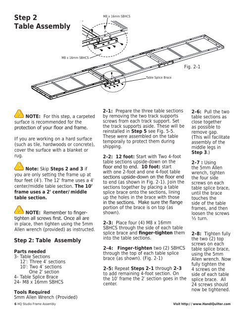
Fig. 2-1<br />
Fig. 2-1<br />
Table Splice Brace<br />
2-1: Prepare the three table sections<br />
by removing the two track supports<br />
screws from each track support. Set<br />
the track supports aside. These will be<br />
reinstalled in Step 5 see Fig. 5-5.<br />
These were assembled on the table<br />
temporaily to protect them during<br />
shipping.<br />
2-2: 12 foot: Start with Two 4-foot<br />
table sections upside-down on the<br />
floor end to end. 10 foot: start<br />
with one 2-foot and one 4-foot table<br />
sections upside-down on the floor end<br />
to end (as shown in Fig. 2-1). Join the<br />
sections together by placing a table<br />
splice brace onto the sections, lining<br />
up the holes in the brace with those<br />
in the sections. Make sure the flange<br />
portion of the brace is on top (as<br />
shown).<br />
2-3: Place four (4) M8 x 16mm<br />
SBHCS through the side of each table<br />
splice brace and finger-tighten them<br />
into the table sections.<br />
2-4: Finger-tighten two (2) SBHCS<br />
through the top of each table splice<br />
brace (as shown). (Fig. 2-1)<br />
2-5: Repeat Steps 2-1 through 2-3<br />
to add remaining 4-foot section. On<br />
the 10’ frame the 2’ section goes in the<br />
center.<br />
Fig. 2-1<br />
2-6: Pull the two<br />
table sections as<br />
close together<br />
as possible to<br />
remove gap.<br />
(This will facilitate<br />
assembly of the<br />
middle legs in<br />
Step 3.)<br />
2-7 : Using<br />
the 5mm Allen<br />
wrench, tighten<br />
the four side<br />
screws on each<br />
table splice brace,<br />
until the brace<br />
touches the<br />
side of the table<br />
frames, and then<br />
loosen the screws<br />
½ turn.<br />
2-8: Tighten fully<br />
the two (2) top<br />
screws on each<br />
table splice brace,<br />
using the 5mm<br />
Allen wrench. Now<br />
fully tighten the<br />
4 screws on the<br />
side of each table<br />
splice brace. All<br />
24 screws should<br />
now be tightened.