hollow lateral extrusion of tubular billets - Umformtechnik
hollow lateral extrusion of tubular billets - Umformtechnik
hollow lateral extrusion of tubular billets - Umformtechnik

You also want an ePaper? Increase the reach of your titles
YUMPU automatically turns print PDFs into web optimized ePapers that Google loves.
HOLLOW LATERAL EXTRUSION OF TUBULAR BILLETS –<br />
A NEWLY DEVELOPED COLD FORGING PROCESS<br />
Dipl.-Ing. Stefan Rudolf<br />
Institute for Metal Forming Technology (IFU), University <strong>of</strong> Stuttgart / Germany<br />
1 Abstract<br />
Increased requirements in the automotive industry concerning reduction <strong>of</strong> CO2 emission require the<br />
development <strong>of</strong> new solutions concerning this aim. Hollow components are particularly suitable for<br />
this goal, especially when dealing with rotating and constantly accelerated masses. Firstly, <strong>hollow</strong><br />
parts contribute to vehicle weight reduction and secondly, the reduction <strong>of</strong> accelerated masses has an<br />
important participation to reduction <strong>of</strong> fuel consumption. Metal forming technologies in general - and<br />
especially bulk metal forming techniques - are suitable for the production <strong>of</strong> <strong>hollow</strong> construction units<br />
for the automotive industry, as they provide economical production from medium size to a large<br />
volume number <strong>of</strong> units.<br />
In this paper, a newly developed bulk metal forming process – the <strong>hollow</strong> <strong>lateral</strong> <strong>extrusion</strong> process <strong>of</strong><br />
<strong>tubular</strong> <strong>billets</strong> is discussed. This metal forming process is subject <strong>of</strong> a joint project between the<br />
Institute <strong>of</strong> Forming Technology and Lightweight Construction <strong>of</strong> TU Dortmund University and the<br />
Institute for Metal Forming Technology <strong>of</strong> the University <strong>of</strong> Stuttgart. Emphasis <strong>of</strong> this work lies on<br />
development <strong>of</strong> the forming process and the required tool concept. Thus, at first the process and its<br />
characteristics are introduced and forming part geometries producible by this process are explained.<br />
Afterwards, tool concepts for different kinds <strong>of</strong> part geometries are demonstrated. Following the<br />
objective <strong>of</strong> entire understanding <strong>of</strong> proposed forming process, numerical and experimental<br />
investigations <strong>of</strong> <strong>hollow</strong> <strong>lateral</strong> <strong>extrusion</strong> <strong>of</strong> <strong>tubular</strong> <strong>billets</strong> have been conducted. Finally, conclusions<br />
will be drawn concerning such newly developed cold forging process.<br />
2 Introduction<br />
At the Institute for Metal Forming Technology <strong>of</strong> the University <strong>of</strong> Stuttgart, a tool concept for the<br />
new cold forging process, “<strong>hollow</strong> <strong>lateral</strong> <strong>extrusion</strong> <strong>of</strong> <strong>tubular</strong> <strong>billets</strong>” was developed and installed. In<br />
standard DIN 8583-6, the <strong>hollow</strong> <strong>lateral</strong> <strong>extrusion</strong> process is described as follows: Lateral <strong>extrusion</strong>,<br />
whereby a branch with arbitrary <strong>hollow</strong> pr<strong>of</strong>ile is extruded at a workpiece. The forming tool nozzle is<br />
thereby composed <strong>of</strong> a divided die and mandrel [1]. In this paper, a process is presented which uses a<br />
<strong>tubular</strong> billet in contradiction to the standard forming process described above. This requires radial<br />
support <strong>of</strong> the billet by an axial interior mandrel during the forming process. The process enables<br />
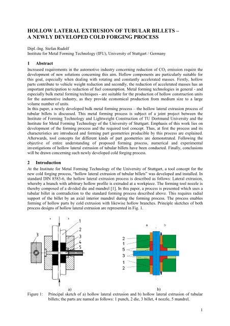
forming <strong>of</strong> <strong>hollow</strong> parts by cold <strong>extrusion</strong> with likewise <strong>hollow</strong> branches. Principle sketches <strong>of</strong> both<br />
process designs <strong>of</strong> <strong>hollow</strong> <strong>lateral</strong> <strong>extrusion</strong> are represented in Fig. 1.<br />
a) b)<br />
Figure 1: Principal sketch <strong>of</strong> a) <strong>hollow</strong> <strong>lateral</strong> <strong>extrusion</strong> and b) <strong>hollow</strong> <strong>lateral</strong> <strong>extrusion</strong> <strong>of</strong> <strong>tubular</strong><br />
<strong>billets</strong>; the parts are named as follows: 1 punch, 2 die, 3 billet, 4 nozzle, 5 mandrel.<br />
1
Fig. 1 a) shows <strong>hollow</strong> <strong>lateral</strong> <strong>extrusion</strong> as described in standard and Fig. 1 b) shows <strong>hollow</strong> <strong>lateral</strong><br />
<strong>extrusion</strong> <strong>of</strong> <strong>tubular</strong> <strong>billets</strong>. The figures show the initial situation <strong>of</strong> the processes on the left side and<br />
the situation during forming on the right side. Some related processes and its characteristics are<br />
mentioned in specialist literature, so in [2] the production <strong>of</strong> a cog wheel hub is described. There, the<br />
last forming stage <strong>of</strong> the sequence <strong>of</strong> operations was <strong>lateral</strong> <strong>extrusion</strong> on the base <strong>of</strong> a <strong>tubular</strong><br />
preformed billet. However, solid teeth were formed contrary to the process described herein. A<br />
problem <strong>of</strong> forming <strong>tubular</strong> <strong>billets</strong> was already mentioned in [2]: the development <strong>of</strong> folding due to the<br />
reduction <strong>of</strong> the surface at the internal area <strong>of</strong> the pressed part. Further examinations describe the<br />
<strong>lateral</strong> <strong>extrusion</strong> <strong>of</strong> a flange [3] on the base <strong>of</strong> <strong>tubular</strong> <strong>billets</strong>, or upsetting <strong>of</strong> flange on a <strong>hollow</strong> billet<br />
[4]. Special tools for <strong>lateral</strong> <strong>extrusion</strong> with additional forming tool shafts and for <strong>lateral</strong> cup <strong>extrusion</strong><br />
are described in [5-9].<br />
Ohashi et al. [10-12] described a process <strong>of</strong> <strong>lateral</strong> <strong>extrusion</strong> <strong>of</strong> pipes with a lost core <strong>of</strong> low melting<br />
alloy. At first the pipe section had to be filled up by low temperature melting alloy. This fill prevented<br />
the tube from collapsing during the <strong>lateral</strong> <strong>extrusion</strong> and had to be melted again after the forming<br />
process to get a <strong>hollow</strong> forming part. In this forming process the wall thickness <strong>of</strong> tube and branches<br />
are strongly connected to each other and it can be compared to tube hydro-forming.<br />
3 Forming part geometries and tool concepts<br />
Through the newly developed process, an expansion <strong>of</strong> the part family <strong>of</strong> cold forging is done as it<br />
enables cold <strong>extrusion</strong> <strong>of</strong> complex <strong>hollow</strong> geometries. A selection <strong>of</strong> component geometries which<br />
could be manufactured by the specified process is represented in Fig. 2. These part geometries can be<br />
classified in three degrees <strong>of</strong> complexity regarding the necessary tool technology. For forming <strong>of</strong><br />
component geometries presented in Fig. 2 a – c) common equipment <strong>of</strong> <strong>lateral</strong> <strong>extrusion</strong> as closing die<br />
device and divided die can be used. The definition <strong>of</strong> the die division plane is done by centrelines <strong>of</strong><br />
branches. Forming <strong>of</strong> <strong>hollow</strong> branches requires inner mandrels to ensure a defined forming process.<br />
Therefore, additional tool shafts are necessary to position, hold and eject such mandrels. The number<br />
<strong>of</strong> tool shafts required for component geometries represented in Fig. 2 a) and Fig. 2 b – c) led to a<br />
subdivision into different degrees <strong>of</strong> complexity. Because additional tool shafts are requisite for the<br />
forming <strong>of</strong> four <strong>hollow</strong> branches, the design <strong>of</strong> the transition area between branches and main body<br />
gets more complex. The tool design <strong>of</strong> <strong>hollow</strong> <strong>lateral</strong> <strong>extrusion</strong> gets even more complex if the<br />
centrelines <strong>of</strong> branches and the main body centreline have more than one intersection point. Therefore,<br />
an additional degree <strong>of</strong> complexity <strong>of</strong> tool design was defined. An example <strong>of</strong> such a forming part<br />
geometry is shown in Fig. 2 d).<br />
a) b) c) d)<br />
Figure 2: Forming part geometries <strong>of</strong> <strong>hollow</strong> <strong>lateral</strong> <strong>extrusion</strong> <strong>of</strong> <strong>tubular</strong> <strong>billets</strong> a) with two<br />
branches, b) with four branches and different kinds <strong>of</strong>, c) branches without rotational<br />
symmetry and d) branches with different intersection points <strong>of</strong> their axles.<br />
For this purpose, the conventional equipment <strong>of</strong> <strong>lateral</strong> <strong>extrusion</strong> comprised <strong>of</strong> press machine and<br />
closing device can only be used conditionally. In this case, the division plane <strong>of</strong> the die is defined by<br />
the main body axis and centrelines <strong>of</strong> the branches. Machine and tool design for such complex<br />
forming parts could be similar to tube hydro forming. Closing travel and closing force could be<br />
generated by a simple hydro forming press. Kinematic functions relevant for this process, for example<br />
punch and branch mandrel motions, could be integrated in an installer tool, see Fig. 3. Two strong and<br />
2
position-controlled hydraulic cylinders could provide the forming force and the travel <strong>of</strong> punches. The<br />
positioning <strong>of</strong> the interior mandrels for forming the <strong>hollow</strong> branches would occur via additional tool<br />
shafts. These kinds <strong>of</strong> tool shafts could be driven electrically, pneumatically or hydraulically;<br />
depending on the force required for holding or rather ejecting the branch mandrels. Compared to the<br />
forming force, the force for ejecting branch mandrels would be low and these tool shafts could<br />
therefore be mounted modularly. The modular design could allow a different arrangement <strong>of</strong> mandrel<br />
tool shafts. Therefore the usage <strong>of</strong> the installer tool for different geometries <strong>of</strong> forming parts would be<br />
possible by using a new arrangement <strong>of</strong> mandrel tool shafts and an exchange <strong>of</strong> die and mandrels.<br />
Figure 3: Concept <strong>of</strong> an installer tool for <strong>hollow</strong> <strong>lateral</strong> <strong>extrusion</strong> <strong>of</strong> forming parts with two or more<br />
intersection points <strong>of</strong> main body centreline and centrelines <strong>of</strong> branches.<br />
4 Experimental setup<br />
4.1 Forming part geometries<br />
First fundamental investigations on the process <strong>hollow</strong> <strong>lateral</strong> <strong>extrusion</strong> <strong>of</strong> <strong>tubular</strong> <strong>billets</strong> were<br />
conducted with forming part geometry with two branches arranged perpendicular to the main body<br />
axis, represented in Fig. 2 a). The branches had a 180° alignment to each other and their centrelines<br />
had the same intersection point. This part geometry was selected for feasibility attempts due to simple<br />
tool design and symmetrical tool load. Restriction on two branches permitted a larger freedom <strong>of</strong><br />
design <strong>of</strong> the transition area between the main mandrel and branch mandrels, than for instance with<br />
four branches. Besides, the tool load was obviously smaller using two branches at 180° alignment<br />
compared to a forming part with only one branch, because the material flow during forming is much<br />
more homogeneous.<br />
For the investigations, the die container diameter was 30 mm and the outside diameters <strong>of</strong> the<br />
branches were 19 mm, the transition was chamfered at a radius <strong>of</strong> 1 mm. By changing punches, mainmandrel<br />
and branch-mandrel forming <strong>of</strong> different part shapes could be performed. First trials were<br />
done with diameter 20 mm <strong>of</strong> the main mandrel and a branch mandrels diameter <strong>of</strong> 12 mm.<br />
4.2 Tool design<br />
A hydraulic closing die device developed at the IFU was used as basis for the experimental setup. Two<br />
hydraulic cylinders pre-stressed by a nitrogen accumulator with 4 litres volume accomplished the<br />
cushion function for die closing and synchronous movement <strong>of</strong> the punches. An additional functional<br />
unit with tool shafts for the branch mandrels integrated into the closing device was used to realize the<br />
kinematics. Fig. 4 shows a principle sketch <strong>of</strong> the experimental setup in opened condition. The upper<br />
part <strong>of</strong> the forming tool was mounted to the press ram and the lower part onto the press table. The<br />
functional unit with additional tool shafts for the branch mandrels was installed at the lower clamping<br />
ring. Forming force is induced from the press table or rather the press ram into the billet by bush-like<br />
punches, which were supported on the pressure pieces and pillar pressure pieces.<br />
3
Figure 4: Principal sketch <strong>of</strong> the testing tool <strong>of</strong> <strong>hollow</strong> <strong>lateral</strong> <strong>extrusion</strong> <strong>of</strong> <strong>tubular</strong> <strong>billets</strong>.<br />
For this special kind <strong>of</strong> <strong>lateral</strong> <strong>extrusion</strong>, a <strong>tubular</strong> billet was used and its inside was supported by the<br />
main mandrel. The tube was transverse punched, to allow positioning the branch mandrels on or rather<br />
in the main mandrel, which would be necessary for the forming process. High quality <strong>of</strong> the parallelfeed<br />
<strong>of</strong> the closing die device is required for the <strong>hollow</strong> <strong>lateral</strong> <strong>extrusion</strong> process. The synchronous<br />
movement <strong>of</strong> the upper and lower halves <strong>of</strong> the closing die device is particularly essential at the<br />
beginning <strong>of</strong> the forming; otherwise critical tool loads can be caused. Different process parameters<br />
could be recorded during the forming tests, which were in detail the travel <strong>of</strong> ram, upper and lower die,<br />
the lower punch force and the pressure <strong>of</strong> closing device cylinders.<br />
5 Results and discussion<br />
5.1 Results <strong>of</strong> finite element calculations<br />
Finite Element analyses were carried out in cooperation with Institute <strong>of</strong> Forming Technology and<br />
Lightweight Construction <strong>of</strong> TU Dortmund University and results were provided. Studies <strong>of</strong> the<br />
material flow related to the variation <strong>of</strong> mandrels diameters showed different types <strong>of</strong> failure at<br />
forming parts. The outside diameter <strong>of</strong> the main body and branches was kept constant, while the main<br />
mandrel diameter was varied from 10 mm to 25 mm and the branch mandrel diameters from 6 mm to<br />
15 mm. Results <strong>of</strong> these investigations are shown in Fig. 5.<br />
a) Free formed branches b) Folding at branches c) Sound part<br />
Figure 5: Results <strong>of</strong> finite element investigations: a) diameter <strong>of</strong> main mandrel 20 mm and branch<br />
mandrels 6 mm, b) diameter <strong>of</strong> main mandrel 15 mm and branch mandrels 6 mm and<br />
c) diameter <strong>of</strong> main mandrel 20 mm and branch mandrels 12 mm.<br />
Unfilled branches occurred at combinations <strong>of</strong> thin walled <strong>billets</strong> and thick walled branches. In this<br />
case, the forming <strong>of</strong> branches was not defined by the tool nozzle because there was no respectively<br />
4
little contact between branches and die. The result <strong>of</strong> finite element analysis with main mandrel<br />
diameter 20 mm and branch mandrel diameters 6 mm is shown in Fig. 5 a). Folding at branches could<br />
be verified at forming part geometries with similar wall thickness <strong>of</strong> billet and branches, folds are<br />
marked red in Fig. 5 b. That folding occurred only at the beginning <strong>of</strong> the process. After the forming<br />
process changed into steady state, folding could be prevented. Most combinations led to forming <strong>of</strong><br />
sound parts, especially if the nozzle cross section area was small or rather the billet cross section area<br />
was large.<br />
Results <strong>of</strong> parameter variation concerning the mandrel diameters are summarized in chart in Fig. 6.<br />
Combinations marked in green colour led to forming <strong>of</strong> sound parts, while the red marked once led to<br />
failure parts with folding. Unfilled branches were formed with combinations marked yellow. The<br />
z-axis <strong>of</strong> the chart shows the specific punch force <strong>of</strong> the forming process. Considered was the punch<br />
force during steady state <strong>of</strong> the forming process referenced to the contact are <strong>of</strong> the punch. It could be<br />
observed, that the specific punch force rose with a low ratio <strong>of</strong> diameters at branches while the ratio <strong>of</strong><br />
diameters at the billet had smaller influence on the specific punch force.<br />
Figure 6: Specific punch force based on billet ratio <strong>of</strong> diameters and branch ratio <strong>of</strong> diameters.<br />
5.2 Results <strong>of</strong> experimental investigations<br />
Forming tests were carried out with the experimental setup described above and <strong>tubular</strong> <strong>billets</strong><br />
machined out <strong>of</strong> bar material with an outside diameter <strong>of</strong> 29.8 mm and inside diameter <strong>of</strong> 20.2 mm.<br />
Additionally, the <strong>billets</strong> were transverse pierced with a cross hole (diameter 12.5 mm). As materials<br />
aluminium alloy EN AW-6060 and steel C4C were used. Aluminium <strong>billets</strong> were coated with zinc<br />
stearate and steel <strong>billets</strong> with phosphate and metal soap previous to the forming tests. Some results <strong>of</strong><br />
experimental forming tests are shown in Fig. 7. The aluminium part in Fig. 7 a) was formed with a<br />
mandrel design, where branch mandrels had a rounded front surface with a corresponding radius as the<br />
mandrel <strong>of</strong> the billet; there was no penetration <strong>of</strong> the mandrels. This design permits small gaps<br />
between main mandrel and branch mandrels. The small formation <strong>of</strong> flash could not be prevented even<br />
at the maximum available holding force. Flash formation could be disabled by a mandrel design where<br />
branch mandrels were positioned in bags at the main mandrel. Figure 7 b) shows a forming part out <strong>of</strong><br />
steel, where a square grid was applied on the surface previous to forming for visioplastic<br />
investigations. Displacement <strong>of</strong> grid intersection points demonstrated the local strain during the<br />
forming process. In Fig. 7 c), forming part with four branches is shown, where, at the inside <strong>of</strong> the<br />
part, folding could be observed.<br />
5
a) Flash formation b) Visioplasticity c) Folding<br />
Figure 7: Results <strong>of</strong> forming test <strong>of</strong> a) aluminium and b) steel with two branches and c) forming <strong>of</strong><br />
four branches with aluminium.<br />
Sensitivity to friction <strong>of</strong> <strong>hollow</strong> <strong>lateral</strong> <strong>extrusion</strong> <strong>of</strong> <strong>tubular</strong> <strong>billets</strong> is obvious due to the high ratio <strong>of</strong><br />
contact surface compared to volume. Punch forces <strong>of</strong> simulations with different shear friction values<br />
and measured punch force <strong>of</strong> a typical forming test were evaluated for detection <strong>of</strong> a shear friction<br />
value via finite element analyses. The comparison <strong>of</strong> measured and calculated punch forces with<br />
different shear friction values for aluminium EN AW-6060 and forming <strong>of</strong> two branches is shown in<br />
Fig. 8. In simulations, the shear friction value m was varied from 0.06 to 0.18. Best fit <strong>of</strong> calculated<br />
and measured punch force curves was achieved by using shear friction value m = 0.12. The correlation<br />
between measured and calculated punch force is good, slight differences at the beginning can be<br />
attributed to the non-consideration <strong>of</strong> elastic behaviour in simulations.<br />
Figure 8: Comparison <strong>of</strong> measured and calculated punch force with different shear friction values m.<br />
6 Conclusion<br />
In the presented paper a new cold forging process “<strong>hollow</strong> <strong>lateral</strong> <strong>extrusion</strong> <strong>of</strong> <strong>tubular</strong> <strong>billets</strong>” was<br />
introduced. This process development expands the limits <strong>of</strong> cold forging concerning geometrically<br />
complex forming parts. Furthermore, the new kind <strong>of</strong> forming parts producible by this process were<br />
presented. Based on the investigations, the following conclusions could be drawn:<br />
• For different part geometries tool concepts were developed.<br />
• Different types <strong>of</strong> failure could be detected by finite element simulations.<br />
• Forming <strong>of</strong> sound parts could be achieved with adequate ratio <strong>of</strong> billet and branch wall<br />
thickness.<br />
• Hollow <strong>lateral</strong> <strong>extrusion</strong> <strong>of</strong> <strong>tubular</strong> <strong>billets</strong> is possible with aluminium and steel.<br />
• The process is friction sensitive because <strong>of</strong> its high ratio <strong>of</strong> contact surface to volume.<br />
6
Acknowledgement<br />
The author would like to thank Deutsche Forschungsgemeinschaft (DFG) for financial support <strong>of</strong> the<br />
research project „Grundlagenuntersuchungen zum Hohl-Quer-Fließpressen von Nebenformelementen“<br />
and the project partner, Institute <strong>of</strong> Forming Technology and Lightweight Construction <strong>of</strong> TU<br />
Dortmund University.<br />
References<br />
[1] DIN 8583 Fertigungsverfahren Druckumformen – Teil 6: Durchdrücken; Einordnung,<br />
Unterteilung, Begriffe. Hrsg.: DIN, Dt. Inst. für Normung e.V., 2003.<br />
[2] Lange, K.; Kammerer, M.; Pöhlandt, K.; Schöck, J.: Fließpressen. Wirtschaftliche Fertigung<br />
metallischer Präzisionswerkstücke, S. 218-219. Springer: Berlin Heidelberg New York, 2008.<br />
[3] Balendra, R.; Qin, Y.: Injection forging: engineering and research. Journal <strong>of</strong> Material<br />
Processing Technology, 145, S. 189-206, 2004.<br />
[4] Liewald, M.; Mletzko, C.: Forschungsschwerpunkte und aktuelle Entwicklungen in der<br />
Massivumformung am Institut für <strong>Umformtechnik</strong> (IFU) der Universität Stuttgart. Neuere<br />
Entwicklungen in der Massivumformung (2009), S. 213-240, MAT INFO<br />
Werkst<strong>of</strong>finformations-gesellschaft mbH, Frankfurt, 2009.<br />
[5] Liewald, M.: Forschungsschwerpunkte und aktuelle Entwicklungen in der Massivumformung<br />
am Institut für <strong>Umformtechnik</strong> (IFU) der Universität Stuttgart. Neuere Entwicklungen in der<br />
Massivumformung (2007), S. 263-282 MAT INFO Werkst<strong>of</strong>f-informationsgesellschaft mbH,<br />
Frankfurt, 2007.<br />
[6] Kudo, H.; Shinozaki, K.: Investigation into multiaxial <strong>extrusion</strong> process to form branched parts.<br />
Proceedings <strong>of</strong> the International Conference on Production Engineering, Part I, p. 314-319,<br />
Tokyo, 1974.<br />
[7] Felde, A.; Rudolf, S.: Erweiterung der Verfahrensgrenzen beim Kaltfließpressen. Neuere<br />
Entwicklungen in der Massivumformung (2009), S. 319-337, MAT INFO<br />
Werkst<strong>of</strong>finformations-gesellschaft mbH, Frankfurt, 2009.<br />
[8] Siegert, K.; Schwager, A.: Werkzeug zum Quer-Fließpressen, Patentschrift DE 199 03 684 B4,<br />
21.04.2005.<br />
[9] Rudolf, S.; Felde, A.; Liewald, M.: Enhancement <strong>of</strong> Forming Limits <strong>of</strong> Magnesium Alloys by<br />
Lateral Extrusion. In: Akkök, M.; Budak, E.; Firat, M.; Kaftanoglu, B. (Edit.): 5th International<br />
Conference and Exhibition on Design and Production <strong>of</strong> Machines and Dies/Molds (2009), S. 81<br />
– 84, Kusadasi, Turkey, 2009.<br />
[10] Ohashi, Matsui, Saotome: The <strong>lateral</strong> <strong>extrusion</strong> <strong>of</strong> copper pipes with a lost core <strong>of</strong> low<br />
temperature melting alloy, Digital Manufacturing Research Center, National Institute <strong>of</strong><br />
Advanced Industrial Science and Technology, Dept. <strong>of</strong> Mechanical System Engineering, Gunma<br />
University, Journal <strong>of</strong> Materials Processing Technology 113, Elsevier, Amsterdam, 2001.<br />
[11] Ohashi, Hayashi: Lateral <strong>extrusion</strong> <strong>of</strong> A6063 aluminum alloy pipes with a lost core, Digital<br />
Manufacturing Research Center, National Institute <strong>of</strong> Advanced Industrial Science and<br />
Technology, School <strong>of</strong> Engineering, Gunma University, Journal <strong>of</strong> Materials Processing<br />
Technology 138, Elsevier, Amsterdam, 2003.<br />
[12] Ohashi, Ito, Shinozaki, Ito, Watari: Lateral <strong>extrusion</strong> <strong>of</strong> a cross fitting with a lost core, Digital<br />
Manufacturing Research Center, National Institute <strong>of</strong> Advanced Industrial Science and<br />
Technology, Oyama National College <strong>of</strong> Technology, Journal <strong>of</strong> Achievements in Materials and<br />
Manufacturing Engineering 24, Gliwice, 2007.<br />
7