Mechanical shaft seals for pumps - Grundfos
Mechanical shaft seals for pumps - Grundfos
Mechanical shaft seals for pumps - Grundfos

You also want an ePaper? Increase the reach of your titles
YUMPU automatically turns print PDFs into web optimized ePapers that Google loves.
14<br />
Introduction<br />
System<br />
pressure<br />
Atmospheric System<br />
pressure pressure<br />
AtmosphericA<br />
B C D<br />
System<br />
pressure<br />
pressure<br />
A B C D<br />
Atmospheric<br />
pressure<br />
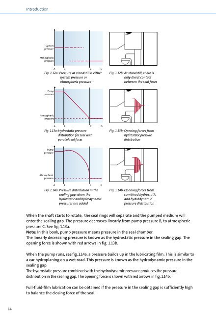
Fig. 1.12a: Pressure at standstill is either<br />
Pump<br />
pressure<br />
Pump<br />
pressure<br />
Atmospheric Pump<br />
pressure<br />
Atmospheric Pump<br />
pressure<br />
system pressure or<br />
atmospheric pressure<br />
When the <strong>shaft</strong> starts to rotate, the seal rings will separate and the pumped medium will<br />
enter the sealing gap. The pressure decreases linearly from pump pressure B, to atmospheric<br />
Pump<br />
pressure C. pressure See fig. 1.13a.<br />
Note: In this book, pump pressure means pressure in the seal chamber.<br />
Pump<br />
The linearly pressure decreasing pressure is known as the hydrostatic pressure in the sealing gap. The<br />
opening <strong>for</strong>ce is shown with red arrows in fig. 1.13b.<br />
Pump<br />
Atmosphere pressure<br />
When the pump runs, see fig. 1.14a, a pressure builds up in the lubricating film. This is similar to<br />
A B C D<br />
a car hydroplaning on a wet road. This pressure is known as the hydrodynamic pressure in the<br />
Atmosphere<br />
sealing gap.<br />
A B C D<br />
The hydrostatic pressure combined with the hydrodynamic pressure 12 produces the pressure<br />
Pump<br />
distribution Atmosphere pressure in the sealing gap. The opening <strong>for</strong>ce is shown with 10 red arrows in fig. 1.14b.<br />
Full-fluid-film lubrication can be obtained if the pressure in the sealing Pumped gap medium is sufficiently pressure<br />
pressure<br />
10 6<br />
high<br />
Water<br />
to balance the closing <strong>for</strong>ce of the seal.<br />
Pump<br />
Atmosphere pressure<br />
A B C D<br />
Atmospheric<br />
A<br />
pressure<br />
B C D<br />
A B C D<br />
Atmospheric<br />
pressure Fig. 1.13a: Hydrostatic pressure<br />
Pump<br />
pressure<br />
Pump<br />
pressure<br />
Atmospheric<br />
pressure<br />
distribution <strong>for</strong> seal with<br />
parallel seal faces<br />
A B C D<br />
A<br />
Atmospheric<br />
pressure<br />
B C D<br />
Fig. 1.14a: Pressure distribution in the<br />
sealing gap when the<br />
hydrostatic and hydrodynamic<br />
pressures are added<br />
A B C D<br />
A B C D<br />
A B C D<br />
Pump<br />
A B C D<br />
Fig. 1.12b: At standstill, there is<br />
only direct contact<br />
between the seal faces<br />
Fig. 1.13b: Opening <strong>for</strong>ces from<br />
hydrostatic pressure<br />
distribution<br />
Fig. 1.14b: Opening <strong>for</strong>ces from<br />
combined hydrostatic<br />
and hydrodynamic<br />
pressure distribution<br />
Absolute ressure [bar] Absolute pressure [bar] pressure [bar]<br />
12<br />
8<br />
48<br />
12<br />
26<br />
10<br />
04<br />
880<br />
2<br />
Water<br />
Vapour<br />
pressure<br />
Vapour<br />
Pumped medium pressure<br />
Normal atmospheric pressure Vapour<br />
Water<br />
pressure<br />
90 100 110 120 130 140 150 Vapour 160 170 180<br />
Pumped medium pressure Temperature [˚C]