Mechanical shaft seals for pumps - Grundfos
Mechanical shaft seals for pumps - Grundfos
Mechanical shaft seals for pumps - Grundfos

Create successful ePaper yourself
Turn your PDF publications into a flip-book with our unique Google optimized e-Paper software.
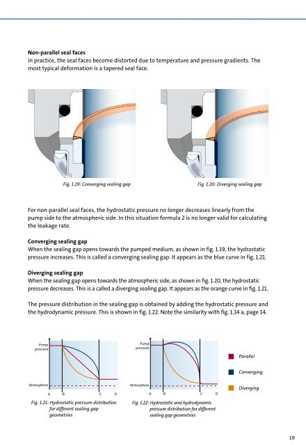
Non-parallel seal faces<br />
System<br />
In practice, pressure the seal faces become distorted due to temperature and pressure gradients. The<br />
most typical de<strong>for</strong>mation is a tapered seal face. Pump<br />
Atmospheric<br />
pressure<br />
Pump<br />
pressure<br />
Atmospheric<br />
pressure<br />
pressure<br />
For non-parallel seal faces, the hydrostatic pressure no longer decreases linearly from the<br />
pump side to the atmospheric side. In this situation A <strong>for</strong>mula B 2 is no longer C Dvalid<br />
<strong>for</strong> calculating<br />
the leakage rate.<br />
Converging Pump sealing gap<br />
pressure<br />
When the sealing gap opens towards the pumped medium, as shown in fig. 1.19, the hydrostatic<br />
pressure increases. This is called a converging sealing gap. It appears as the blue curve in fig. 1.21.<br />
Diverging sealing gap<br />
Pump<br />
Atmospheric<br />
pressure<br />
When pressure the sealing gap opens towards the atmospheric side, as shown in fig. 1.20, the hydrostatic<br />
pressure decreases. This is a called a diverging sealing gap. It appears as the orange curve in fig. 1.21.<br />
The pressure distribution in the sealing gap is obtained by adding the hydrostatic pressure and<br />
the hydrodynamic pressure. This is shown Atmosphere in fig. 1.22. Note the similarity with fig. 1.14 a, page 14.<br />
Pump<br />
pressure<br />
Atmosphere<br />
Fig. 1.21: Hydrostatic pressure distribution<br />
<strong>for</strong> different sealing gap<br />
geometries<br />
Pump<br />
pressure<br />
A B C D<br />
A B C D<br />
A B C D<br />
A B C D<br />
Atmospheric<br />
pressure<br />
pressure<br />
Atmospheric<br />
pressure<br />
Pump<br />
pressure<br />
Pump<br />
pressure<br />
A B C D<br />
A B C D<br />
Fig. 1.19: Converging sealing gap Fig. 1.20: Diverging sealing gap<br />
Atmospheric<br />
Atmosphere<br />
A B C D<br />
A B C D<br />
Fig. 1.22: Hydrostatic and hydrodynamic<br />
pressure distribution <strong>for</strong> different<br />
12<br />
sealing gap geometries<br />
ute pressure [bar]<br />
10<br />
8<br />
6<br />
Water<br />
Pumped medium pressure<br />
Absolute pressure [bar]<br />
Parallel<br />
12<br />
10<br />
Converging<br />
Diverging<br />
Vapour<br />
8<br />
6<br />
4<br />
2<br />
0<br />
80<br />
Water<br />
Pumped medi<br />
90 100 110 120<br />
19