introduction - Kentucky Transportation Cabinet
introduction - Kentucky Transportation Cabinet
introduction - Kentucky Transportation Cabinet

You also want an ePaper? Increase the reach of your titles
YUMPU automatically turns print PDFs into web optimized ePapers that Google loves.
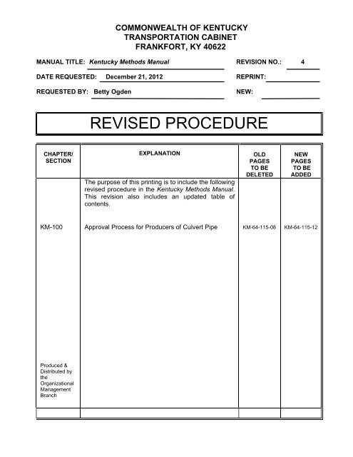
COMMONWEALTH OF KENTUCKY<br />
TRANSPORTATION CABINET<br />
FRANKFORT, KY 40622<br />
MANUAL TITLE: <strong>Kentucky</strong> Methods Manual REVISION NO.: 4<br />
DATE REQUESTED: December 21, 2012 REPRINT:<br />
REQUESTED BY: Betty Ogden NEW:<br />
CHAPTER/<br />
SECTION<br />
KM-100<br />
Produced &<br />
Distributed by<br />
the<br />
Organizational<br />
Management<br />
Branch<br />
REVISED PROCEDURE<br />
EXPLANATION<br />
The purpose of this printing is to include the following<br />
revised procedure in the <strong>Kentucky</strong> Methods Manual.<br />
This revision also includes an updated table of<br />
contents.<br />
Approval Process for Producers of Culvert Pipe<br />
OLD<br />
PAGES<br />
TO BE<br />
DELETED<br />
KM-64-115-08<br />
NEW<br />
PAGES<br />
TO BE<br />
ADDED<br />
KM-64-115-12
COMMONWEALTH OF KENTUCKY<br />
TRANSPORTATION CABINET<br />
FRANKFORT, KY 40622<br />
MANUAL TITLE: <strong>Kentucky</strong> Methods Manual REVISION NO.: 3<br />
DATE REQUESTED: August 24, 2012 REPRINT:<br />
REQUESTED BY: Brad Webb NEW:<br />
CHAPTER/<br />
SECTION<br />
KM-400<br />
Produced &<br />
Distributed by<br />
the<br />
Organizational<br />
Management<br />
Branch<br />
REVISED PROCEDURE<br />
EXPLANATION<br />
The purpose of this printing is to include the revised<br />
policy, “Requirements for Process-Control Testing and<br />
Inspection of Asphalt Mixtures by the Contractor” in the<br />
<strong>Kentucky</strong> Methods Manual. This revision also includes<br />
an updated table of contents.<br />
Requirements for Process-Control Testing and<br />
Inspection of Asphalt Mixtures by the Contractor<br />
OLD<br />
PAGES<br />
TO BE<br />
DELETED<br />
KM-64-426-09<br />
NEW<br />
PAGES<br />
TO BE<br />
ADDED<br />
KM-64-426-12
KENTUCKY METHODS<br />
GUIDANCE MANUAL<br />
http://www.kytc.state.ky.us/materials/KYMethods.htm<br />
COMMONWEALTH OF KENTUCKY<br />
TRANSPORTATION CABINET<br />
DEPARTMENT OF HIGHWAYS<br />
November 2008<br />
Distributed by<br />
Organizational Management Branch<br />
Office of Human Resource Management
INTRODUCTION<br />
The testing procedures in this manual are utilized for the sampling and testing of<br />
materials incorporated into <strong>Kentucky</strong> <strong>Transportation</strong> <strong>Cabinet</strong> projects. ASTM, AASHTO,<br />
or other referenced standards also complement these methods. Applicable methods are<br />
defined by references in the <strong>Kentucky</strong> Standard Specifications for Road and Bridge<br />
Construction, Project Plans, or Special Notes for the appropriate material. The <strong>Kentucky</strong><br />
<strong>Transportation</strong> <strong>Cabinet</strong>’s Division of Materials within the Department of Highways<br />
develops and maintains the methods described in this manual. The division office in<br />
Frankfort serves as the <strong>Transportation</strong> <strong>Cabinet</strong>’s central laboratory. When a method<br />
refers to a testing section, that section is a unit within the division.<br />
The Division of Materials updates this manual annually, both online and in hard copy.<br />
Printed versions of the <strong>Kentucky</strong> Methods that are older than one year may be out-ofdate.<br />
In an effort to provide the highway construction industry, public, and<br />
<strong>Transportation</strong> <strong>Cabinet</strong> personnel with current information, the division maintains these<br />
methods on its website (http://www.kytc.state.ky.us/materials/KYMethods.htm). Any<br />
user having difficulty accessing this location may contact his or her local district<br />
materials engineer (DME) or the division for assistance.<br />
If you have comments or other suggestions, please contact the division at (502) 564-<br />
3160 or the following mailing address:<br />
<strong>Kentucky</strong> <strong>Transportation</strong> <strong>Cabinet</strong><br />
Division of Materials<br />
1227 Wilkinson Boulevard<br />
Frankfort, KY 40601<br />
To obtain a copy of this manual, contact the Organizational Management Branch, Office<br />
of Human Resource Management, at (502) 564-4610.
TABLE OF CONTENTS<br />
KENTUCKY METHODS<br />
GENERAL<br />
KM 64-001-08 KENTUCKY TRANSPORTATION CABINET QUALIFICATION PROGRAM<br />
FOR TECHNICIANS<br />
KM 64-002-08 NUCLEAR GAUGES USED FOR DENSITY OF VARIOUS MATERIALS<br />
KM 64-003-10 APPROVAL OF NEW MATERIALS TO BE USED ON TRANSPORTATION<br />
PROJECTS IN KENTUCKY<br />
PHYSICAL<br />
KM 64-101-08 TESTING AND ACCEPTANCE OF STEEL REINFORCING BARS<br />
(UNCOATED AND COATED)<br />
KM 64-102-08 TEST PROCEDURES FOR THE PLANT INSPECTION OF EPOXY COATED<br />
STEEL REINFORCEMENT.<br />
KM 64-103-05 PREPARATION AND TESTING OF WELD SPECIMENS<br />
KM 64-106-05 TEST PROCEDURES FOR EPOXY COATED REINFORCING BAR<br />
INSTALLATION MATERIALS<br />
KM 64-107-05 FALLING - HEAD WATER PERMEABILITY OF FILTER FABRIC:<br />
DETERMINATION OF PERMEABILITY COEFFICIENT AND FLOW RATE<br />
AT A GIVEN CHANGE IN WATER HEAD<br />
KM 64-108-05 QUALIFICATION OF GAS METAL ARC (MIG) WELDERS AND<br />
PREPARATION AND TESTING OF MIG WELD SPECIMENS<br />
KM 64-109-06 QUALIFICATION OF STEEL REINFORCEMENT TACK WELDERS<br />
KM 64-110-05 QUALIFICATION OF SHIELDED METAL ARC WELDERS<br />
KM 64-112-05 NUMERICAL LIMITS FOR COMPARING TEST RESULTS (INDEPENDENT<br />
ASSURANCE SAMPLING AND TESTING PROGRAM)<br />
KM 64-113-08 SAMPLING MATERIALS BY RANDOM NUMBER SAMPLING<br />
KM 64-114-08 CAMERA/VIDEO INSPECTION OF PIPE WITH ALTERNATE METHODS OF<br />
DEFLECTION MEASUREMENT<br />
KM 64-115-12 APPROVAL PROCESS FOR PRODUCERS OF CULVERT PIPE<br />
<strong>Kentucky</strong> Methods, December, 2012<br />
1
TABLE OF CONTENTS<br />
CHEMISTRY<br />
KM 64-201-08 EVALUATION OF RETROREFLECTIVITY ON INTERSECTION PAVEMENT<br />
MARKINGS USING PORTABLE HAND-OPERATED INSTRUMENTS<br />
KM 64-202-10 EVALUATION OF RETROREFLECTIVITY ON PAVEMENT MARKINGS<br />
USING PORTABLE HAND-OPERATED INSTRUMENTS<br />
KM 64-203-10 EVALUATION OF RETROREFLECTIVITY ON PERMANENT PAVEMENT<br />
MARKINGS USING MOBILE 30 METER GEOMETRY INSTRUMENTS<br />
KM 64-209-08 PULL - OUT TEST FOR RE-BAR ANCHOR SYSTEMS<br />
KM 64-210-08 CHLORIDE CONTENT (CONCRETE ADMIXTURES)<br />
KM 64-221-08 AGRICULTURAL LIMESTONE<br />
KM 64-222-08 CALCIUM CHLORIDE<br />
KM 64-224-08 CHEMICAL ANALYSIS OF LIMESTONE, FINE AGGREGATE, QUICKLIME<br />
AND HYDRATED LIME<br />
KM 64-225-08 SODIUM CHLORIDE<br />
KM 64-226-08 WATER FOR USE WITH CEMENT<br />
KM 64-227-08 WATER - BORNE PRESERVATIVES<br />
KM 64-241-08 FERTILIZER<br />
KM 64-242-08 HERBICIDES<br />
KM 64-243-08 SAMPLING AND TESTING SOILS (CHEMICAL)<br />
KM 64-250-08 ANALYSIS FOR ISOCYANATE CONTENT<br />
KM 64-251-08 HUMIDITY CHAMBER ANALYSIS OF TRAFFIC PAINTS<br />
KM 64-253-08 CHEMICAL ANALYSIS OF FLY ASH AND MICROSILICA<br />
KM 64-254-08 CHEMICAL ANALYSIS OF CEMENT<br />
KM 64-256-08 RESISTANCE TESTING OF STRUCTURAL STEEL COATINGS TO METHYL<br />
ETHYL KETONE<br />
KM 64-257-08 ANALYSIS FOR HINDERED AMINE LIGHT STABILIZER (HALS)<br />
KM 64-258-08 MEASUREMENT AND ACCEPTANCE OF FILM THICKNESS OF<br />
STRUCTURAL STEEL COATINGS<br />
KM 64-261-08 TEST METHOD FOR ANALYSIS FOR AMINE CONTENT<br />
KM 64-262-08 TEST METHOD FOR THE ANALYSIS OF BASE NUMBER<br />
KM 64-263-08 TEST METHOD FOR ANALYSIS OF CALCIUM SULFONATE<br />
KM 64-264-08 TEST METHOD FOR ANALYSIS OF EPOXY CONTENT<br />
KM 64-265-08 TEST METHOD FOR INSOLUBLE RESIDUE IN CARBONATE<br />
AGGREGATES<br />
KM 64-266-08 PERFORMANCE BASED EVALUATION AND ACCEPTANCE OF<br />
STRUCTURAL STEEL COATING SYSTEMS<br />
KM 64-267-10 QUALIFICATIONS OF MONITORING SYSTEMS FOR PAVEMENT<br />
MARKINGS APPLICATION VEHICLES<br />
<strong>Kentucky</strong> Methods, December, 2012<br />
2
TABLE OF CONTENTS<br />
CONCRETE & CEMENT<br />
KM 64-301-08 SAMPLING FRESH CONCRETE<br />
KM 64-302-08 SLUMP OF PORTLAND CEMENT CONCRETE<br />
KM 64-303-08 AIR CONTENT OF FRESHLY MIXED CONCRETE BY THE PRESSURE<br />
METHOD<br />
KM 64-304-08 AIR CONTENT OF FRESHLY MIXED CONCRETE BY THE VOLUMETRIC<br />
METHOD<br />
KM 64-305-08 MAKING AND CURING CONCRETE STRENGTH (COMPRESSIVE) TEST<br />
SPECIMENS IN THE FIELD<br />
KM 64-306-08 TEST FOR FREE MOISTURE CONTENT OF CONCRETE AGGREGATES<br />
KM 64-308-08 METHOD OF MEASURING LENGTH OF DRILLED CORES<br />
KM 64-309-08 CORING RIGID PAVEMENT FOR THICKNESS<br />
KM 64-311-08 CONCRETE “TRUCK MIXER” INSPECTION PROCEDURE<br />
KM 64-312-08 CALIBRATION OF CONTINUOUS-TYPE MIXERS (CONCRETE MOBILES)<br />
KM 64-313-08 MEASUREMENT OF BRIDGE DECK REINFORCEMENT COVER<br />
KM 64-314-08 EVALUATION OF CONCRETE CYLINDER RESULTS<br />
KM 64-315-08 CORING BRIDGE DECK OVERLAYS FOR THICKNESS<br />
KM 64-316-08 SAMPLING PORTLAND CEMENT<br />
KM 64-317-08 COMPRESSIVE STRENGTH OF CYLINDRICAL CONCRETE SPECIMENS<br />
USING NEOPRENE CAPS<br />
KM 64-318-08 TEMPERATURE OF FRESHLY MIXED CONCRETE<br />
KM 64-320-08 METHOD FOR APPROVAL OF USING SELF CONSOLIDATING CONCRETE<br />
(SCC)<br />
KM 64-322-08 ESTIMATING CONCRETE STRENGTH BY THE MATURITY METHOD<br />
KM 64-323-09 QUALIFICATION PROCESS FOR PRODUCERS OF READY MIX CONCRETE<br />
KM 64-324-08 UNIT WEIGHT OF CONCRETE<br />
KM 64-325-08 ACCEPTANCE PROCEDURES FOR FLY ASH FOR CONCRETE<br />
<strong>Kentucky</strong> Methods, December, 2012<br />
3
TABLE OF CONTENTS<br />
ASPHALT<br />
KM 64-401-05 CALIBRATING AND CHECKING COLD-FEED FLOW ON ASPHALT<br />
MIXING PLANTS<br />
KM 64-404-05 SAMPLING LIQUID ASPHALT MATERIALS<br />
KM 64-405-05 EXTRACTION OF BINDER FROM ASPHALT PAVING MIXTURES<br />
KM 64-407-08 SIEVE ANALYSIS OF AGGREGATE FROM ASPHALT MIXING PLANTS<br />
KM 64-409-06 COMPRESSION - DEFLECTION TEST FOR PREFORMED COMPRESSION<br />
JOINT SEALS<br />
KM 64-411-09 PREPARING INGREDIENT MATERIALS FOR, AND PERFORMING, A<br />
LABORATORY MIX DESIGN OF AN ASPHALT MIXTURE<br />
KM 64-415-08 NON-VOLATILE TEST FOR ASPHALT MASTIC<br />
KM 64-416-08 PLASTIC SET TEST FOR ASPHALT MASTIC<br />
KM 64-420-09 CORING ASPHALT PAVEMENT FOR THICKNESS<br />
KM 64-421-05 ESTABLISHING THE JOB - MIX FORMULA OF ASPHALT MIXTURES BY<br />
THE CONTRACTOR<br />
KM 64-422-08 ASPHALT RELEASING AGENT<br />
KM 64-423-08 EFFECT OF WATER ON COHESION OF COMPACTED ASPHALT<br />
MIXTURES<br />
KM 64-424-08 METHOD FOR DESIGNING OPEN-GRADED FRICTION COURSE<br />
MIXTURES<br />
KM 64-425-05 SAMPLING ASPHALT MIXTURES<br />
KM 64-426-12 REQUIREMENTS FOR PROCESS-CONTROL TESTING AND INSPECTION<br />
OF ASPHALT MIXTURES BY THE CONTRACTOR<br />
KM 64-427-05 METHOD FOR DESIGNING ASPHALT MIXTURES CONTAINING<br />
RECYCLED - ASPHALT PAVEMENT (RAP)<br />
KM 64-433-08 WET-SIEVE ANALYSIS OF AGGREGATES USED IN ASPHALT MIXTURES<br />
KM 64-434-09 DETERMINATION OF MOISTURE CONTENT IN ASPHALT MIXTURES<br />
(RAPID FIELD TEST)<br />
KM 64-435-05 METHOD FOR ACCEPTANCE OF ASPHALT MIXTURES BY MIXTURE<br />
PROPERTY ANALYSIS<br />
KM 64-436-08 ASPHALT BINDER CONTENT DETERMINATION OF ASPHALT MIXTURES<br />
BY PLANT RECORDATION<br />
KM 64-437-08 DETERMINATION OF ASPHALT BINDER CONTENT OF ASPHALT<br />
MIXTURES USING THE NUCLEAR ASPHALT CONTENT GAUGE<br />
KM 64-438-08 ASPHALT BINDER CONTENT DETERMINATION OF ASPHALT<br />
MIXTURES BASED ON THE MAXIMUM SPECIFIC GRAVITY<br />
KM 64-439-08 SAMPLING ASPHALT MIXTURES FROM THE PAVING SITE<br />
<strong>Kentucky</strong> Methods, December, 2012<br />
4
TABLE OF CONTENTS<br />
KM 64-442-09 METHOD FOR CORING AND DETERMINING PERCENT OF SOLID<br />
DENSITY OF IN-PLACE, COMPACTED, ASPHALT MIXTURE COURSES<br />
KM 64-443-09 METHOD FOR VERIFYING A CONTRACTOR’S LABORATORY MIX<br />
DESIGN<br />
KM 64-444-06 PERFORMANCE-GRADED (PG) ASPHALT BINDER APPROVED SUPPLIER<br />
CERTIFICATION (ASC) PROGRAM<br />
KM 64-445-05 EMULSIFIED ASPHALT SUPPLIER CERTIFICATION (EASC) PROGRAM<br />
KM 64-446-08 CHEMICAL INTERACTION TESTS FOR TRAFFIC LOOP ENCAPSULANT<br />
KM 64-447-08 CURE TEST FOR TRAFFIC LOOP ENCAPSULANT<br />
KM 64-448-09 EVALUATION OF ASPHALT PAVEMENT WITH SUBSTANDARD<br />
PROPERTIES<br />
KM 64-449-05 DETERMINING THE PERMEABILITY OF IN-PLACE HOT-MIX ASPHALT<br />
(HMA) USING THE AIR-INDUCED PERMEAMETER (AIP)<br />
GEOTECHNICAL<br />
KM 64-501-08 DETERMINING THE CALIFORNIA BEARING RATIO OF LABORATORY<br />
COMPACTED SOILS AND SOIL - AGGREGATE MIXTURES<br />
KM 64-502-08 CONSOLIDATED, UNDRAINED TRIAXIAL COMPRESSION TEST ON<br />
COHESIVE SOILS<br />
KM 64-503-08 MEASUREMENT OF PORE PRESSURE IN SOILS<br />
KM 64-511-08 MOISTURE - DENSITY RELATIONS (PROCTOR DENSITY)<br />
KM 64-512-08 ONE POINT PROCTOR METHOD<br />
KM 64-513-08 DETERMINATION OF SLAKE DURABILITY INDEX<br />
KM 64-514-08 JAR SLAKE TEST<br />
KM 64-519-08 PARTICLE SIZE ANALYSIS OF SOILS (HYDROMETER TEST)<br />
KM 64-520-08 SUBGRADE CHEMICAL STABILIZATION TEST<br />
KM 64-521-08 UNCONSOLIDATED, UNDRAINED COMPRESSIVE STRENGTH OF<br />
COHESIVE SOILS IN TRIAXIAL COMPRESSION<br />
KM 64-522-08 UNCONFINED COMPRESSION TEST ON SOIL<br />
KM 64-523-08 UNCONFINED COMPRESSION TEST ON ROCK<br />
<strong>Kentucky</strong> Methods, December, 2012<br />
5
TABLE OF CONTENTS<br />
AGGREGATES<br />
KM 64-604-08 DETERMINATION OF THE PERCENTAGE OF SHALE IN AGGREGATE<br />
KM 64-605-08 SPECIFIC GRAVITY AND ABSORPTION OF FINE AGGREGATE<br />
KM 64-606-08 PERCENTAGE OF MATERIAL FINER THAN A NO. 200 SIEVE BY USE OF A<br />
PYCNOMETER (WASH TEST)<br />
KM 64-608-08 AGGREGATE PRODUCER QUALITY CONTROL<br />
KM 64-610-08 SOUNDNESS OF AGGREGATE BY USE OF SODIUM SULFATE<br />
KM 64-615-08 DETERMINATION OF COAL AND LIGNITE IN AGGREGATES<br />
KM 64-618-08 METALLIC IRON CONTENT IN SLAG<br />
KM 64-620-08 WET SIEVE ANALYSIS OF FINE AND COARSE AGGREGATE<br />
KM 64-623-08 PORE INDEX VALUE OF AGGREGATE<br />
KM 64-626-08 RESISTANCE OF CONCRETE TO FREEZE-THAW TESTING<br />
KM 64-627-08 PROCEDURE FOR VERIFYING OVEN TEMPERATURE<br />
KM 64-628-08 PROCEDURE FOR VERIFYING MEASURED SIEVES<br />
KM 64-629-08 LENGTH CHANGE OF HARDENED CONCRETE DUE TO ALKALI-<br />
CARBONATE REACTIVITY<br />
<strong>Kentucky</strong> Methods, December, 2012<br />
6
<strong>Kentucky</strong> Method 64-001-08<br />
Revised 04/02/08<br />
Supersedes 64-001-05<br />
Dated 01/28/05<br />
1. SCOPE:<br />
KENTUCKY TRANSPORTATION CABINET<br />
QUALIFICATION PROGRAM FOR TECHNICIANS<br />
1.1. According to Title 23, Part 637, Code of Federal Regulations (23 CFR 637), FHWA’s<br />
“Quality Assurance Procedures for Construction”, all acceptance and verification sampling<br />
and testing must be performed by “qualified personnel”.<br />
1.2. As defined in the Quality Assurance Program for Materials Testing and Acceptance, the<br />
<strong>Kentucky</strong> Department of Highways has established a Quality Assurance (QA)<br />
program to ensure that materials and workmanship incorporated into any highway<br />
construction project are in reasonable conformity with the requirements of the approved<br />
plans and specifications, including any approved changes. This QA program allows for the<br />
use of validated, contractor-performed, quality control (QC) test results as part of an<br />
acceptance decision. It also allows for the use of test results obtained by commercial<br />
laboratories in the Independent Assurance (IA) program as well as in acceptance decisions.<br />
2. REFERENCED DOCUMENTS: <strong>Kentucky</strong> Department of Highways Quality Assurance<br />
Program for Materials Testing and Acceptance<br />
3. QUALIFICATION PROGRAM STEERING COMMITTEE (QPSC): The Qualification<br />
Program is overseen by a Steering Committee consisting of the following representatives:<br />
State Highway Engineer<br />
Deputy State Highway Engineer for Project Delivery<br />
Director, Division of Construction<br />
Director, Division of Materials<br />
Director, Division of Employee Support<br />
Division of Materials Qualification Coordinator<br />
Representative, Federal Highway Administration<br />
Representative, <strong>Kentucky</strong> Ready Mixed Concrete Association (KRMCA)<br />
Representative, <strong>Kentucky</strong> Association of Highway Contractors (KAHC)<br />
KM 64-001-08<br />
1
Representative, <strong>Kentucky</strong> Crushed Stone Association (KCSA)<br />
Representative, Plantmix Asphalt Industry of <strong>Kentucky</strong> (PAIKY)<br />
4. QUALIFICATION POLICIES:<br />
4.1. Required qualifications are primarily: 1) sample and test oriented or 2) demonstration of<br />
knowledge or expertise for a specific discipline.<br />
4.1.1. Qualifications required for sampling and testing as part of a QA program. These<br />
qualifications are required, as applicable, for the QC effort, acceptance, verification,<br />
or IAS program. To qualify, an individual must successfully perform the specific<br />
tests and necessary calculations required for each qualification type in the presence<br />
of an authorized evaluator. Successful performance is defined as demonstrating the<br />
ability to properly perform the key elements for each test method. If the individual<br />
fails to demonstrate the ability to perform a test, the individual may be allowed one<br />
retest per test method at the evaluator’s discretion.<br />
4.1.2. Qualifications required for demonstration of knowledge or expertise associated with<br />
items of work. These qualifications are required, as applicable, for project oversight<br />
when specific items of work are being performed.<br />
4.2. The individual must pass a written examination administered by an authorized ev aluator.<br />
An individual failing the written examination may request a retest. The individual may be<br />
allowed one retest at the evaluator’s discretion. The retest must be requested, scheduled<br />
and administered within 30 days of the notification of failure. Failure to pass the second<br />
written examination shall be considered as failing the entire qualification.<br />
4.3. Qualification of an individual is valid for not more than five years. After that time, the<br />
individual must qualify again. Under the requirements of the QA program, interim<br />
evaluations will be permitted when appropriately justified.<br />
4.4. Test questions and other examination data used to administer this qualification program are<br />
subject to reuse and are considered confidential and exempt from pu blic records inspection.<br />
5. EXAMINATION METHODS AND POLICIES:<br />
5.1. A standard set of examinations for each qualification will be used statewide. With the<br />
exception of national qualifications, the examinations will be developed by a committee<br />
composed of personnel from some or all of the following: Division of Materials, Division<br />
of Construction, and appropriate industry representatives.<br />
5.2. In addition, the individual may be required to participate in proficiency sample testing<br />
administered by the qualification authority to validate the qualification. The result of the<br />
proficiency samples will be evaluated for compliance with acceptable tolerance limits. If the<br />
comparison of test results does not comply with the tolerances, an engineering review of the<br />
KM 64-001-08<br />
2
test procedures and equipment shall be performed immediately to determine the source of<br />
the discrepancy. Corrective actions must be identified, and incorporated as appropriate,<br />
prior to the individual performing additional testing on that test method.<br />
6. DISQUALIFICATION PROCEDURES: A qualified individual can be disqualified for any of the<br />
following reasons:<br />
6.1. Failure to pass requalification requirements and/or provide payment of fees, initial<br />
or requalification.<br />
6.2. Found to be guilty of falsifying test results, records, and/or reports or any willful departure<br />
from approved policy/procedure. Allegations of falsification or willful departure will be<br />
made to the QPSC in writing. The allegations will contain the name, address, and signature<br />
of the individual(s) making the allegation. The allegations will be investigated by the QPSC.<br />
The accused and the individual(s) making the allegation will be given the opportunity to<br />
appear before the QPSC. All involved parties will be notified in writing o f the findings by<br />
the QPSC. Any warranted actions will be imposed according to the guidance contained<br />
herein. Decisions regarding allegations may be appealed in writing to the QPSC which will<br />
consider such written appeals and take such action considered appropriate.<br />
6.2.1. First offense would result in a 12-month revocation of qualification status in all<br />
qualification types. Prior to reinstatement, the individual shall again successfully<br />
complete qualification classes.<br />
6.2.2. Second offense would result in a permanent loss of qualification status in all<br />
qualification types.<br />
KM 64-001-08<br />
3
APPROVED<br />
6.3. Found to be guilty of improperly performing tests, failing to perform tests, or being<br />
incapable of performing tests and documented by a qualified technicia n. The documentation<br />
(“Report of Violation” form, copy attached) must include the date(s), time(s), location(s),<br />
occurrence(s) of non-conformance, and signature of the qualified technician reporting the<br />
incident.<br />
6.3.1. First offense would result in a letter of reprimand from the QPSC.<br />
6.3.2. Second offense would result in a 30-day revocation of qualification status.<br />
6.3.3. Third offense would result in a revocation of qualification status. The individual<br />
may obtain qualification again after a six-month period and successfully completing<br />
the appropriate qualification class(es).<br />
DIRECTOR<br />
DIVISION OF MATERIALS<br />
DATE 04/02/08<br />
<strong>Kentucky</strong> Method 64-001-08<br />
Revised 04/02/08<br />
Supersedes 64-001-05<br />
Dated 01/28/05<br />
KM 64-001-08<br />
4<br />
km00108.doc
KENTUCKY QUALIFICATION PROGRAM FOR TECHNICIANS<br />
REPORT OF VIOLATION<br />
The undersigned <strong>Kentucky</strong> Qualified Technician has witnessed and documented violation(s) of the<br />
Technician Qualification Program. These violations are outlined in Section 7 of KM 64 -001, <strong>Kentucky</strong><br />
<strong>Transportation</strong> <strong>Cabinet</strong> Qualification Program for Technicians. The qualified technician noted in violation<br />
is:<br />
______________________________ ________________________________<br />
Name Certification No.<br />
____________________________________________________________________<br />
Date(s) of Violation<br />
____________________________________________________________________<br />
Time(s) of Violation<br />
____________________________________________________________________<br />
Location(s) of Violation<br />
Description of the violation (Attach additional sheets if necessary):<br />
_____________________________________________________________________________________<br />
_____________________________________________________________________________________<br />
_____________________________________________________________________________________<br />
_____________________________________________________________________________________<br />
_____________________________________________________________________________________<br />
_____________________________________________________________________________________<br />
______________________ ______________________ ____________________<br />
Qualified Technician Inspector ID Number Date<br />
________________________________<br />
Signature<br />
KM 64-001-08<br />
5
<strong>Kentucky</strong> Method 64-002-08<br />
Revised 02/29/08<br />
Supersedes 64-002-03<br />
Dated 02/04/03<br />
NUCLEAR GAUGES USED FOR DENSITY OF VARIOUS MATERIALS<br />
1. SCOPE: This method is used to determine the in-place density of various materials using the<br />
backscatter or direct transmission method. This procedure supplements the manufacturer’s<br />
instruction manual by outlining procedures for densit y testing.<br />
2. APPARATUS:<br />
2.1. Nuclear density gauge: An instrument containing two radioactive sources, combined wit h<br />
density and moisture detectors and other basic components, housed in a single unit for the<br />
backscatter method or direct transmission. The devices considered in this method are<br />
Troxler Model 3411B, Troxler Model 3430, Troxler 3440 and Humbolt 5001EZ.<br />
2.2. A portable reference block: This block is used to establish standard counts and as a<br />
repeatable reference for verifying stability of the gauge.<br />
2.3. AC charger for office charging and a DC charger for charging fro m a cigarette lighter in<br />
vehicle for emergency field use. Humbolts do not have chargers.<br />
2.4. Drill rod with puller: Used with a hammer to create the hole required for direct<br />
transmission measurements.<br />
2.5. Scraper plate: Functions as a guide for the drill rod and for test -site surface preparation.<br />
2.6. 4-lb. Hammer: To drive the drill rod.<br />
3. CALIBRATION PROCEDURE (Daily Standard Count):<br />
3.1. Perform all calibration requirements daily, or more frequently if transportation,<br />
background, or other conditions necessitate. The importance of obtaining a set of accurate<br />
standard counts cannot be over-emphasized. The accuracy of measurements made with<br />
this instrument is directly related to the accuracy of the standard counts. Refer to the<br />
manufacturer’s instruction manual for calibrat ion procedures.<br />
3.2. Turn-On/Warm-Up:<br />
3.2.1. Model 3411B: Place the gauge on the reference block. Turn the “PWR/TIME”<br />
switch to the “SLOW” position, and allow the gauge to warm up for at least 10<br />
minutes before calibration.<br />
3.2.2. Model 3430: Place the gauge on the reference block. Press the “ON” switch. The<br />
gauge will undergo a 300-second self-test. After the self-test is complete, the<br />
gauge is ready for calibrat ion.<br />
KM 64-002-08<br />
1
3.2.3. Model 3440: Place the gauge on the reference block. Press the “ON” switch. The<br />
gauge will undergo a 300-second self-test. After the self-test is complete, the<br />
gauge is ready for calibrat ion.<br />
3.2.4. Humboldt 5001EZ: Place the gauge on reference block. Press “PWR” switch.<br />
The gauge will undergo a series of self-test routines. After the self-test is complete,<br />
the gauge is ready for calibration.<br />
3.3. With all models, the source rod is located on the block opposite the metal plate. Ensure the<br />
gauge base makes firm contact with the surface of the reference block and is flush against<br />
the metal plate.<br />
3.4. Remove the lock from the trigger, and ensure the handle is indexed in the standard or safe<br />
position.<br />
3.5. Obtain the standard counts as follows:<br />
3.5.1. Model 3411B:<br />
3.5.1.1. Press the “SHIFT” key, and while ho lding it down, press and release<br />
the “STANDARD/MEASURE” key.<br />
3.5.1.2. Release the “SHIFT” key. For 4 minutes the density count will<br />
accumulate. Notice “ERR” message in upper left -hand corner.<br />
3.5.2. Model 3430:<br />
3.5.2.1. Press the “STD” key. The gauge will display the last standard<br />
counts accumulated along with “new std cnt?”<br />
3.5.2.2. Press the “ON/YES” key.<br />
3.5.2.3. Press the “START” key.<br />
3.5.2.4. The count time will start, with the time remaining displayed in<br />
seconds, beginning at 240 seconds.<br />
3.5.3. Model 3440:<br />
3.5.3.1. Press the “STD” key. The gauge will display the last standard<br />
counts accumulated along with “new std cnt?”<br />
3.5.3.2. Press the “ON/YES” key.<br />
3.5.3.3. Press the “START” key.<br />
3.5.3.4. The count time will start, with the time remaining displayed in<br />
seconds, beginning at 240 seconds.<br />
KM 64-002-08<br />
2
3.5.4. Humboldt 5001EZ:<br />
3.5.4.1. Press the “STD/STAT” key. The gauge will display the last<br />
standard counts accumulated along with date and time.<br />
3.5.4.2. Press the F3.<br />
3.5.4.3. The count time will start. After the density and moisture standard<br />
will be stored in the registers.<br />
3.6. After obtaining the standard counts, record the counts in the logbook supplied with the<br />
gauge.<br />
3.6.1. Model 3411B:<br />
3.6.1.1. Return the source rod to the safe position before viewing the data.<br />
3.6.1.2. The gauge will display the density standard (DS) count after the<br />
completion of the count. To obtain the moisture standard (MS)<br />
count, press the “MS” key.<br />
3.6.1.3. View the density standard count again by pressing the “DS” key, if<br />
necessary. View the counts anytime by pressing the “DS” and<br />
“MS” keys. These counts remain in the gauge unt il it is turned off.<br />
3.6.2. Model 3430: After the standard count is complete, scroll through the menu to<br />
display the “DS” and “MS.” These counts remain in the gauge unt il another<br />
standard count is taken, regardless of whether or not the gauge is turned off.<br />
3.6.3. Model 3440: After the standard count is complete, scroll through the menu to<br />
display the “DS” and “MS”. These counts remain in the gauge unt il another<br />
standard count is taken, regardless of whether or not the gauge is turned off.<br />
3.6.4. Humboldt 5001EZ: After the standard count is complete and there are no errors in<br />
the standard count, the display will show the “DS” and “MS”.<br />
3.7. In general, a sudden shift of more than one percent in the density standard count, or two<br />
percent in the moisture standard count, as compared to the average of the previous four<br />
sets, would indicate some abnormality in gauge operation or procedure. In this case, repeat<br />
the calibration procedure. If problems persist, contact the central office radiation safety<br />
officer (RSO).<br />
4. OPERATING THE GAUGE: Use the manufacturer’s instruction manual when operating the<br />
Troxler or Humboldt gauges. Note: Time settings for a recorded test shall be Normal (1 minute)<br />
or Slow (4 minutes).<br />
4.1. Place the gauge on as smooth a surface as possible (concrete, aggregate, or compacted<br />
soil). Depress the handle trigger, and move the rod to the backscatter posit ion. Be certain<br />
that the handle clicks into the slot on the index rod. Determine this position by pulling up<br />
KM 64-002-08<br />
3
and down on the handle without depressing the.<br />
4.2. Density and Moisture Determinations:<br />
4.2.1. Model 3411B:<br />
4.2.1.1. Set the “PWR/TIME” switch on “NORM (one minute count),” and<br />
press the “START” key. Note that “ERR” appears in the display.<br />
4.2.1.2. At the end of the “NORM” time period, “ERR” will disappear. The<br />
test is now complete. Return the source rod to the safe position<br />
before viewing the data. Read the density count and moisture count<br />
by pressing the “DC” and “MC” keys, respect ively.<br />
4.2.2. Model 3430:<br />
4.2.2.1. Press the “TIME” key.<br />
4.2.2.2. Press the “up arrow” or the “down arrow” until the gauge displays<br />
“1 min.”<br />
4.2.2.3. Press the “ENTER” key.<br />
4.2.2.4. Press the “START” key. The gauge will then accumulate counts for<br />
one minute, displaying the count time in seconds. The gauge will<br />
display a density, moisture, or count value when the count is<br />
complete. Return the source rod to the safe position. View all test<br />
data by scrolling through the data with the “up arrow” or the “down<br />
arrow” on the keyboard.<br />
4.2.3. Model 3440:<br />
4.2.3.1. Press the “TIME” key.<br />
4.2.3.2. Press the “up arrow” or the “down arrow” until the gauge displays<br />
“1 min.”<br />
4.2.3.3. Press the “ENTER” key.<br />
4.2.3.4. Press the “START” key. The gauge will then accumulate counts for<br />
one minute, displaying the count time in seconds. The gauge will<br />
display density, moisture, or count value when the count is<br />
complete. Return the source rod to the safe position. View all test<br />
data by scrolling through the data with the “up arrow” or the “down<br />
arrow” on the keyboard.<br />
4.2.4. Humboldt 5001EZ:<br />
4.2.4.1. Press the “MEAS” key.<br />
KM 64-002-08<br />
4
4.2.4.2. The gauge will then accumulate counts for one minute. The gauge<br />
will display density and moisture when the count is complete.<br />
Return the source rod to the safe position.<br />
4.3. The moisture and density backscatter measurement is now complete. If testing soil or<br />
aggregate base, another option is a mo isture and density direct transmission measurement<br />
obtained by punching a hole using the drill rod, guide, and a hammer. Insert the source rod<br />
into the prepared hole to the proper depth. The hole for the source rod should always be at<br />
least two inches deeper than the depth of measurement. Proceed as directed by Instruction<br />
Manual. Remember to set the “DEPTH” switch to the appropriate depth.<br />
4.4. The gauge displays computed results in pounds per cubic foot (PCF). The data may now<br />
be processed to obtain the desired parameter, provided both the test depth and target<br />
density have been entered.<br />
4.5. Set the “DEPTH” switch on “BS” (backscatter) and the “MOISTURE CORRECTION” on<br />
“+00.” Press the “WD” key, and the value of the wet densit y will appear in the display.<br />
Press the “DD” key, and the value of the dry density will appear. Repeat for “M” (moisture<br />
content) and “%M” (percent of moisture). When obtaining the moisture measurement on<br />
concrete, this value will be the water equivalency of the hydration of the concrete.<br />
4.6. To control the top yellow row of keys press and hold the “SHIFT” key. For instance, for<br />
“% of Proctor” press and hold the “SHIFT” key and press the “% PR” key.<br />
4.7. The value “z” is a user -defined value for target density. Knowing the correct proctor<br />
density for the material that is being tested is critical. Ensure that the proctor density is set<br />
in the density gauge. Refer to Model’s Manufacturer Instruction Manual.<br />
5. TEST SITE:<br />
5.1. Determine test sites in accordance with <strong>Kentucky</strong> Method (KM) 64-113, Sampling<br />
Materials by Random Number Sampling, for acceptance purposes. For control strip<br />
qualification or other informational testing, the <strong>Kentucky</strong> <strong>Transportation</strong> <strong>Cabinet</strong> (KYTC)<br />
may select test sites without utilizing KM 64-113.<br />
5.2. In order to obtain optimum accuracy from the gauge, perform site preparation. The<br />
method for site preparation varies, depending on the surface and the type of test performed.<br />
6. DIRECT TRANSMISSION PROCEDURE (FOR SOILS):<br />
6.1. Using the scraper plate supplied with the gauge, carefully scrape the surface to a smooth<br />
condition, removing all dried and loose material. If the scraping act ion dislodges surface<br />
material, remove it; fill the vo ids with fine material, and light ly tamp the surface.<br />
6.2. Place the scraper plate in the middle of the site, and drive the drill rod into the soil using a<br />
4-lb. hammer. Placing one foot on the plate will prevent it fro m slipping or otherwise<br />
damaging the site by allowing the drill rod to move fro m side to side. Ensure that the rod<br />
has been driven 2” deeper than the test depth.<br />
KM 64-002-08<br />
5
6.3. Utilize the drill rod puller for extraction of the drill rod. Place the puller on the drill rod<br />
before driving. With one foot remaining on the scraper plate, rotate the drill rod to loosen<br />
it, and then remove it up and out of the hole. Ensure no damage to the hole occurs.<br />
6.4. Place the gauge over the site so that the source rod aligns with the hole. Depress the<br />
trigger, and push the source rod down to the properly indexed posit ion at the desired depth.<br />
With the operator facing the scaler module, pull the gauge toward the operator to seat the<br />
source rod against the side of the hole. Perform the test at a 6 -in. depth.<br />
6.4.1. Model 3411B: the depth selection switch is graduated from “BS” (backscatter)<br />
through 12 in. Dial in the appropriate depth with the switch. Gauges are calibrated<br />
on 2-in. increments only.<br />
6.4.2. Model 3430: press the “DEPTH” key. Select the correct depth with the “up arrow”<br />
or the “down arrow.” When the correct depth is displayed, press the<br />
“START/ENTER” key.<br />
6.4.3. Model 3440: press the “DEPTH” key. Select the correct depth with the “up arrow”<br />
or the “down arrow.” When the correct depth is displayed, press the<br />
“START/ENTER” key.<br />
6.4.4. Humboldt 500EZ: Press the F3 to increase or F4 to decrease the value. When the<br />
correct depth is displayed, press the “MEAS” key.<br />
7. BACKSCATTER PROCEDURE (FOR AGGREGATE BASE AND CONCRETE):<br />
7.1. Situations may occur in which it is impossible to drive the drill rod into the material<br />
without destroying the surface. In this case, use the backscatter procedure.<br />
7.2. Under backscatter conditions, site preparation must be more thorough and all vo ids filled<br />
as closely as possible to the same, or similar, density as the compacted material. The<br />
gauge must not rock on its base when seated.<br />
7.3. When the source rod is indexed into the backscatter posit ion, be careful not to bypass the<br />
intended index notch and force the source rod tip on, or into, the material.<br />
7.4. Soils and aggregate compaction are based on a dry density; concrete compaction is based<br />
on a wet density. Record only the wet density measurement on concrete.<br />
8. REPORTING:<br />
7.4.1. Model 3411B: refer to the manufacturer’s instruction manual.<br />
7.4.2. Model 3430: refer to the manufacturer’s instruction manual.<br />
7.4.3. Model 3440: refer to the manufacturer’s instruction manual.<br />
7.4.4. Humboldt 5001EZ: refer to the manufacturer’s instruction manual.<br />
KM 64-002-08<br />
6
8.1. Record the station number and transverse location of each test location.<br />
8.2. Report the density results on the applicable SiteManager Nuclear Density Excel<br />
Spreadsheet (DENSACPT.XLS or DENSITY.XLS).<br />
9. PRECAUTIONS:<br />
APPROVED<br />
9.1. Ensure all personnel operating nuclear gauges are trained in the principles o f nuclear<br />
testing and all related safety practices. Operators shall wear personnel mo nitoring devices<br />
such as badges.<br />
9.2. Ensure all nuclear gauge users refer to, and observe, the safet y precautions in the Division<br />
of Construction’s Guidance Manual and Manufacturer’s Operational Manual for Nuclear<br />
Gauges.<br />
9.3. Perform all tests at least 30 ft. from other radioact ive material.<br />
9.4. Perform all tests at least two feet from any vertical projections (retaining walls, ditches,<br />
etc.) and at least three inches fro m the pavement edge or joint.<br />
9.5. Keep all personnel without monitoring devices at least 15’ from the nuclear gauge.<br />
DIRECTOR<br />
DIVISION OF MATERIALS<br />
DATE 02/29/08<br />
<strong>Kentucky</strong> Method 64-002-08<br />
Revised 02/29/08<br />
Supersedes 64-002-03<br />
Dated 02/04/03<br />
KM 64-002-08<br />
7<br />
Km00208.doc
<strong>Kentucky</strong> Method 64-003-10<br />
Dated 03/18/10<br />
1. SCOPE:<br />
APPROVAL OF NEW MATERIALS TO BE USED ON<br />
TRANSPORTATION PROJECTS IN KENTUCKY<br />
1.1 With advances in technology comes the arrival of new and innovative products to be used<br />
in transportation projects. The <strong>Kentucky</strong> <strong>Transportation</strong> <strong>Cabinet</strong> (KYTC) receives<br />
numerous requests for the use of new materials or materials that have been improved or<br />
modified.<br />
1.2 New products may not meet current specifications or may not have specifications approved<br />
by KYTC. If there is not a central approval process for new or modified materials, there is<br />
the potential for inferior or potentially dangerous products to be used on <strong>Kentucky</strong>’s<br />
highways.<br />
1.3 The New Product Review Committee (NPRC) has the duty to review new products to<br />
ensure that they are safe, durable and economical for the citizens of the Commonwealth.<br />
The NPRC decides what products are approved for use on <strong>Kentucky</strong> highways but does<br />
not make a recommendation that any particular product be used over another competing<br />
product.<br />
2. COMMITTEE: The NPRC will be composed of:<br />
Voting members:<br />
Executive Director, Office of Project Delivery & Preservation<br />
Executive Director, Office of Project Development<br />
Director, Division of Construction<br />
Director, Division of Maintenance<br />
Director, Division of Traffic Operations<br />
Director, Division of Materials<br />
Director, Division of Structural Design<br />
Director, Division of Highway Design<br />
Non-Voting Members:<br />
KyPEL Administrator and Chairman of Committee<br />
Representative of <strong>Kentucky</strong> Association of Highway Contractors<br />
Representative of Plantmix Asphalt Industry of <strong>Kentucky</strong><br />
Representative of <strong>Kentucky</strong> Concrete Pavement Association<br />
Representative of <strong>Kentucky</strong> <strong>Transportation</strong> Center<br />
KM 64-003-10<br />
1
3. PRODUCTS REVIEWED BY THE COMMITTEE :<br />
4. PROCESS:<br />
Any product that is new to the market or a product that has been substantially modified should be<br />
reviewed by the New Product Review Committee if it is to be used in the construction or<br />
maintenance of <strong>Kentucky</strong> highways. Products such as reflectors, barriers, asphalt additives, and<br />
concrete patching materials will come before the committee if they are not already approved for<br />
highway construction and maintenance. Items that are strictly used as equipment for construction<br />
or maintenance will not go before the committee.<br />
4.1 The approval process is broken into phases that allow for a product to advance to<br />
approval<br />
and placement on the List of Approved Materials. The progress of a product is tracked<br />
with the <strong>Kentucky</strong> Product Evaluation List (KyPEL). KyPEL is an online application<br />
process that allows the manufacturer or vendor to see the progress of a product or to see<br />
comments about the product. The manufacturer or vendor can then update attachments,<br />
submit samples of the product, or make clarifications.<br />
4.2 KyPEL is handled by an administrator who has the responsibility of ensuring that products<br />
are evaluated fairly and consistently. The administrator assigns a product to a particular<br />
phase based on a set of guidelines. It is also the responsibility of the administrator to<br />
disseminate information to all parties that must make recommendations concerning<br />
products. The administrator must track assignments to ensure that the products do not<br />
languish in any one phase for too long.<br />
4.3 The process begins when a manufacturer or vendor accesses KyPEL via the internet at:<br />
http://www.ktc.uky.edu/kytc/kypel/login.php. The administrator reviews the information<br />
that is submitted and follows the guidelines in assigning phases.<br />
4.4 Phases:<br />
4.4.1 Phase I- Product has been submitted and is pending initial review.<br />
During Phase I, it is the responsibility of the administrator to ensure that there is<br />
enough information about the product for an initial review to be conducted.<br />
Vendors and manufacturers will have up to three months to submit the necessary<br />
information to enter into Phase II. If at the end of the second month there is no<br />
information on a product to review, the administrator will attempt to make contact<br />
with the person responsible for the submittal. If after three months there is no<br />
further information to review, the administrator will place the product in Phase<br />
XIII.<br />
KM 64-003-10<br />
2
4.4.2 Phase II- The product is under preliminary review by appropriate<br />
section(s)/division(s) and awaiting recommendation(s) to the chair from the<br />
appropriate section(s)/division(s). Minimal study of available literature is<br />
necessary at this stage.<br />
Phase II is begun with the administrator assigning the product to the appropriate<br />
section(s)/division(s). The personnel responsible for reviewing the information are<br />
to determine if the product falls under a current specification or if specifications do<br />
not exist. The appropriate personnel make a recommendation to the committee<br />
based on the initial information that has been provided. Personnel are to ensure<br />
that their comments are strictly based on whether there is potential for the product<br />
to be used in a KYTC project. The administrator must review the comments from<br />
the assigned personnel. If the product is not covered under an existing<br />
specification, then the administrator assigns the product to Phase III and sends the<br />
information to the committee members. If the product falls under existing<br />
specifications, then the product is placed in Phase VI.<br />
4.4.3 Phase III- Product is under detailed laboratory and/ or literature review by the<br />
NPRC.<br />
The administrator receives all comments and recommendations from committee<br />
members. If the majority of the committee members decide that a product has<br />
potential to be used in KYTC projects, then the material is assigned to Phase IV. If<br />
the committee determines that the product is already covered by another<br />
specification or does not need to be approved, then the product is assigned to either<br />
Phase VI or Phase VIII. If the committee determines that the product does not have<br />
the potential to be used in KYTC projects, then the product is not approved and<br />
placed into Phase XIII. Committee members will be given 14 days to vote on the<br />
product. If the committee feels that additional information is needed, the<br />
administrator will make contact with the manufacturer to obtain the necessary<br />
information.<br />
4.4.4 Phase IV- Product has been approved for experimental use by the New Product<br />
Review Committee. The product may be used on a limited basis; however, change<br />
orders must be submitted and approved prior to use of the product. The product<br />
will be monitored for performance for two years, but the performance period may<br />
be changed depending on the type of product and susceptibility to weathering. If<br />
the product performs poorly and poses a safety risk, the product may be removed<br />
before scheduled replacement.<br />
When a product is entered into Phase IV the product may be used in a construction<br />
or maintenance project provided it has been approved prior to use. It is up to the<br />
KM 64-003-10<br />
3
product manufacturer/ vendor to approach the contractor about using the product.<br />
A change order will have to be approved and the administrator must be notified<br />
prior to installation. It may be necessary for the administrator and a representative<br />
of the manufacturer or vendor to be present during installation. The administrator<br />
will attempt to inspect the product periodically to ensure that the product is<br />
performing satisfactorily and is not posing a safety risk. At the end of Phase IV,<br />
the New Product Review Committee will review the performance of the product.<br />
If a product has been in Phase IV for two years and has not been used on a project,<br />
then the administrator will take the product back to the committee to determine if<br />
the phase should continue or if the evaluation should be terminated.<br />
4.4.5 Phase V- The product has been approved for use by the New Products Review<br />
Committee. The contractor must have the product approved by the KYTC and the<br />
Federal Highway Administration (FHWA) (if applicable) prior to use of the<br />
product on a project. Standard Specifications or Special Notes are being developed<br />
for this type of material/product.<br />
Prior to entering Phase V, a product has been tested experimentally and the results<br />
of the experimental usage have been reviewed by the NPRC. The Committee has<br />
approved the product for use on <strong>Kentucky</strong> highways. The administrator is working<br />
with others within KYTC to develop Standard Specifications or Special Notes.<br />
4.4.6 Phase VI- Current specifications exist for this type of product. The manufacturer<br />
must submit samples and/ or provide required information to have the product<br />
approved and placed on the List of Approved Materials (if applicable).<br />
Products that are placed in Phase VI typically will not have been reviewed by the<br />
committee. Products that are in Phase VI already have specifications and will be<br />
tested to determine if they meet the existing specifications. If the product meets the<br />
specifications then it can be placed on the List of Approved Materials.<br />
4.4.7 Phase VII- Reserved<br />
4.4.8 Phase VIII- Not a product to be evaluated by the New Products Review Committee.<br />
If the product is not to be utilized in highway and bridge construction or<br />
maintenance then it does not fall under the review of the committee. If the product<br />
is considered to be equipment that will be used in the construction or maintenance<br />
of highways or bridges it will not be reviewed by the committee.<br />
4.4.9 Phase IX- Reserved<br />
KM 64-003-10<br />
4
4.4.10 Phase X- Product has been approved and special notes or specifications exist.<br />
4.4.11 Phase XI- Reserved<br />
4.4.12 Phase XII- Reserved<br />
5. IMMEDIATE NEED:<br />
4.4.13 Phase XIII A-G Product not approved for use in <strong>Kentucky</strong> highway or bridge<br />
construction.<br />
If a product is in immediate need, the contractor and/or the KYTC office responsible for<br />
installation or use should notify the KyPEL administrator of the need. The request can be<br />
submitted by email, fax, or letter. The KyPEL administrator will notify the members of the<br />
committee of the urgent need. The product can be approved for a conditional Phase IV if two or<br />
more voting committee members agree that the product is needed immediately. The committee<br />
will review the product within six months of installation to determine if the product should remain<br />
in Phase IV. The product cannot be approved for phases V, VI, X, or XIII until it has been<br />
reviewed and approved by the full committee. If the product is not used within three months of<br />
the request then the NPRC will decide if the product should remain in Phase IV or be placed into<br />
another phase.<br />
APPROVED<br />
EXECUTIVE DIRECTOR<br />
OFFICE OF PROJECT DELIVERY<br />
& PRESERVATION<br />
DATE 03/18/10<br />
<strong>Kentucky</strong> Method 64-003-10<br />
Dated 03/18/10<br />
KM 64-003-10<br />
5<br />
KM00310.DOC
<strong>Kentucky</strong> Method 64-101-08<br />
Revised 05/19/08<br />
Supersedes 64-101-06<br />
Dated 05/04/06<br />
1. SCOPE:<br />
TESTING AND ACCEPTANCE OF STEEL REINFORCING BARS<br />
(UNCOATED AND COATED)<br />
1.1. The <strong>Kentucky</strong> <strong>Transportation</strong> <strong>Cabinet</strong>’s (KYTC) acceptance procedure for plain (uncoated)<br />
steel reinforcing bars requires certification of test results for all heats , then appropriate<br />
project sampling, followed by testing. Certified test results may only originate from<br />
manufacturers included on the Division of Material’s (Division) current List of Approved<br />
Materials (LAM).<br />
The KYTC's acceptance procedures for epoxy coated steel reinforcing bars requires<br />
certification of all bars prior to coating. The epoxy coating shall be applied only by epoxy<br />
coaters included on the LAM.<br />
1.2 Whoever supplies reinforcing steel to a KYTC project, whether the manufacturer, coater, or<br />
fabricator, must provide proper documentation. This shall consist of at a minimum 1) TC<br />
64-122 for each shipment, 2) certified mill test reports for each heat, 3) certifications from<br />
the steel and powder manufacturers and from the coater. Certifications shall include a<br />
statement of compliance with the applicable specifications and shall be dated and signed by<br />
a responsible party.<br />
2. MANUFACTURER'S RESPONSIBILITIES:<br />
2.1. Gaining LAM Status: Reinforcing steel manufacturers desiring to be included on the LAM<br />
shall abide by all requirements listed herein. The manufacturer shall submit a Quality<br />
Control Program to the Division. For a Quality Control Program to be acceptable it must<br />
meet the following criteria:<br />
2.1.1. Testing equipment shall be tested and calibrated by an approved independent<br />
company at least annually and a copy of the certification submitted to the Division.<br />
2.1.2. A Quality Control Inspector shall perform all tests and inspections as required in<br />
section 2.3.<br />
2.1.3. Identity of heats shall be maintained from melting pot to delivery to fabricator,<br />
coater and ultimately the jobsite.<br />
2.1.4. Records of test results shall be available for inspection for five years.<br />
2.1.5. A certified mill test shall be furnished with each shipment of steel. The certified mill<br />
test shall contain the results of all applicable ASTM tests on a per heat basis:<br />
KM 64-101-08<br />
1
that is; nominal weight, yield and tensile strengths, elongation, 180 o bend test, height<br />
of deformations and phosphorous content.<br />
2.1.6. Reinforcing steel shipped directly to the jobsite by the manufacturer shall meet the<br />
requirements of section 2.2. and section 3.1.2.<br />
2.1.7. The manufacturer shall participate as required in a cooperative test program with the<br />
Division as described in section 2.4.<br />
2.2. Heat Identification Requirements: The fabricator or manufacturer shall provide a definite<br />
means whereby the various heat numbers in each shipment can be positively identified and,<br />
if necessary, separated from the remainder of the shipment. Individual bundles of bars shall<br />
be identified by tags or other acceptable means and tied into sub -bundles as necessary to<br />
provide positive heat identification.<br />
2.3. Testing And Acceptance Criteria:<br />
2.3.1. General:<br />
2.4. Cooperative Testing:<br />
2.3.1.1. All testing shall be performed in accordance with standard ASTM<br />
procedures. Manufacturers shall have their testing equipment<br />
calibrated at least annually and copies of the calibration results shall<br />
be furnished to the KYTC. Additionally, regular cooperative testing<br />
shall be performed by the KYTC and the manufacturer. Samples ,<br />
when requested, shall be submitted prepaid by the manufacturer.<br />
2.3.1.2. Bar properties to be tested are yield strength, tensile strength,<br />
elongation, 180 o bend, weight per foot, deformations and phosphorus<br />
content. The manufacturer shall provide chemical, mechanical and<br />
physical properties for each heat being considered for approval.<br />
Strength results will be rounded to the nearest 1000 psi.<br />
2.3.1.3. The failure of any property of any test specimen shall be cause for<br />
rejection of the heat.<br />
2.4.1. Samples for ASTM A 615 cooperative testing shall consist of 20 bars (2 bars per<br />
heat) from 10 different heats (if possible) 60” in length, representing each bar size<br />
produced up to and including a #11 (36 mm) bar. If the number of bar sizes<br />
produced are fewer than 10, make up the difference by duplicating bar sizes<br />
sufficient to represent 10 different heats (if possible). If the cooperating facility also<br />
produces ASTM A 706 steel, provide two additional samples for each of these sizes<br />
as well with as many different heats represented as possible.<br />
2.4.2. Cooperative testing shall consist of the following test data; YIELD in pounds per<br />
square inch, TENSILE in pounds per square inch, ELONGATION in percent, and<br />
KM 64-101-08<br />
2
WEIGHT in pounds per foot. Each bar will be submitted to the appropriate bend<br />
test as well. The methods of tests shall be in accordance with ASTM A 615, A<br />
706, A 955 and/or A 996 as appropriate. Submit test data from the cooperating<br />
facility for the above parameters on the heats of steel represented by the samples and<br />
provide actual weight/length [lb/ft] of the samples tested at your facility. Indicate<br />
what bar sizes the mill produces, what type steel (A 615 or A 706), and if the<br />
samples are of coil or straight stock. Also submit a copy of the most recent<br />
calibration/certification for tensile equipment utilized.<br />
2.4.3. The average test results for the same heat and bar size run at each laboratory shall<br />
not vary more between laboratories than the following:<br />
Pounds Per Foot + 1 Percent<br />
Yield + 4 Percent<br />
Tensile + 4 Percent<br />
Elongation + 3 Percent<br />
2.4.4. Any heat failing to meet section 2.4.3 may be resampled. The resampling shall<br />
consist of three bars from the same heat.<br />
2.4.5. At least 90% of comparable test values must be within the limits of section 2.4.3 to<br />
obtain or continue LAM status.<br />
2.5. Removal From LAM: Maintaining LAM status will be conting ent upon compliance with all<br />
requirements contained in this section and section 5.<br />
3. FABRICATOR'S RESPONSIBILITIES:<br />
3.1. Gaining LAM Status: Fabricators desiring to be included on the LAM shall abide by all<br />
applicable requirements listed herein.<br />
3.1.1. Purchase reinforcing steel from a manufacturer or epoxy coater on the LAM<br />
maintained by the Division.<br />
3.1.2. Identity of heats shall be maintained at all times and documentation shall be provided<br />
as required in section 2.2. Coated reinforcing steel shall also be accompanied by<br />
copies of all documentation provided by the coater.<br />
3.2. Removal From LAM: Maintaining LAM status will be contingent upon compliance with all<br />
requirements contained in this section and section 5.<br />
4. COATER'S RESPONSIBILITIES:<br />
4.1. Gaining LAM Status: Epoxy coaters desiring to be included on the LAM shall abide by all<br />
requirements listed herein. The coater must agree to abide by the current edition of<br />
<strong>Kentucky</strong> Standard Specifications for Road and Bridge Construction (Specifications)<br />
KM 64-101-08<br />
3
(specifically section 811.10) and submit and obtain approval of its Quality Control Program<br />
from the Division. For the Quality Control Program to be acceptable, the coater must, as a<br />
minimum, comply with the following:<br />
4.1.1. All reinforcing steel for coating shall be from a manufacturer on the LAM<br />
maintained by the Division.<br />
4.1.2. Identity of heats shall be maintained at all times as required in section 2.2.<br />
4.1.3. Use only epoxy powder shown on the LAM. A written manufacturer's certification<br />
for this resin shall be submitted annually to the Division.<br />
4.1.4. Perform the following quality functions (KM 64-102) and record test results:<br />
4.1.4.1. Monitor blast cleaning operations at least every two hours to insure<br />
conformance to pictorial standards A Sp 10, B Sp 10, or C Sp 10 of<br />
SSPC Vis 1 and to maintain proper etch pattern.<br />
4.1.4.2. Insure that bars are coated within 8 hours after blast cleaning.<br />
4.1.4.3. Check temperature of bar just prior to coating to insure powder<br />
manufacturer's application temperature is met.<br />
4.1.4.4. Check daily to insure that the minimum curing time recommended by<br />
the powder manufacturer has elapsed prior to the coated bars<br />
reaching the water bath.<br />
4.1.4.5. Check the coating thickness with a thumb wheel pulloff gauge . The<br />
thickness gauge will be calibrated for accuracy at least daily and the<br />
results recorded on the quality control report. The thickness will be<br />
measured according to ASTM A 775. The coating thickness shall be<br />
7 to 12 mils inclusive. Thickness measurements will be t aken as<br />
often as necessary, but at least one bar from each 60 minutes of<br />
production time shall be documented. If the coating on the bar<br />
checked does not meet the thickness requirements, that bar shall be<br />
rejected and additional bars (usually adjacent to the original test bar)<br />
shall be checked to determine the extent of the problem. Either an<br />
insufficient or excessive film thickness will be cause for rejection of<br />
the coated bars.<br />
4.1.4.6. Check for Continuity of Coating:<br />
4.1.4.6.1. An operational in-line 67.5-V, 80,000 ohms wet-sponge type<br />
direct-current holiday (defect) detector with an automated<br />
holiday counter shall be provided for each strand of the<br />
production line. In-line and hand-held holiday detectors shall<br />
be operated and maintained in accordance with the<br />
KM 64-101-08<br />
4
manufacturer’s instructions.<br />
4.1.4.6.2. Compare the accuracy of the in-line holiday detector with a<br />
hand-held holiday detector at least once a production shift.<br />
Holiday counts from both the hand-held and in-line holiday<br />
detectors shall be recorded on the inspection form.<br />
4.1.4.6.3. When any bar has more than two holidays per linear foot or a<br />
total defective area exceeding 0.25 percent of the surface area<br />
per linear foot, the holidays shall be repaired with approved<br />
touch-up material. When any bar has more than five holidays<br />
per linear foot or a total defective area exceeding 0.5 percent<br />
of the surface area per linear foot, the bar shall be rejected.<br />
When any bar is found that requires touch-up or rejection,<br />
additional bars (usually adjacent to the problem bar) shall be<br />
checked to determine the extent of the problem.<br />
4.1.4.7. Check the flexibility of the coating by bending one bar of each size<br />
coated per shift, but with a minimum of two tests per eight hour shift.<br />
The bars are to be bent around a pin equal in diameter to the bar size<br />
in inches as per ASTM A 775 Table I. Bend the bar at room<br />
temperature through an arc of 180 o after rebound. The coating<br />
should not show any visible cracks.<br />
4.1.5 Submit CRSI (Concrete Reinforced Steel Institute) ECR Plant Certification, the<br />
latest audit results and any response to CRSI.<br />
4.2. Removal From LAM: Maintaining LAM status will be contingent upon compliance with all<br />
requirements contained in this section and section 5.<br />
5. CONDITIONS FOR REMOVAL FROM LAM:<br />
5.1. The following conditions will result in probation or removal from the LAM:<br />
5.1.1. Failure to comply with the minimum criteria for each approved list.<br />
5.1.2. Frequently recurring instances of check sample failure.<br />
5.1.3. Inclusion of unapproved heats or grades in shipments.<br />
5.1.4. Lack of sufficient heat identification.<br />
5.1.5. Furnishing of non-specification material.<br />
5.2. Once a manufacturer, fabricator or coater is removed from an approved list , reinstatement<br />
may be requested after a period of three months, providing the reason(s) for removal is<br />
(are) recognized and corrected.<br />
KM 64-101-08<br />
5
6. TESTING OF JOBSITE CHECK SAMPLES:<br />
APPROVED<br />
6.1. Plain and Coated Steel: All six mechanical test properties listed in 2.1.5 shall be performed<br />
on each sample.<br />
6.2. Coated Steel: In Addition to 6. 1, thickness of coating will be measured according to<br />
ASTM A 775.<br />
DIRECTOR<br />
DIVISION OF MATERIALS<br />
DATE 05/19/08<br />
<strong>Kentucky</strong> Method 64-101-08<br />
Revised 05/19/08<br />
Supersedes 64-101-06<br />
Dated 05/04/06<br />
Attachments<br />
KM 64-101-08<br />
6<br />
km10108.doc
KENTUCKY TRANSPORTATION CABINET TC 64-122<br />
DEPARTMENT OF HIGHWAYS Rev. 5/92<br />
DIVISION OF MATERIALS<br />
FABRICATOR’S HEAT NUMBER IDENTIFICATION<br />
OF REINFORCING BARS<br />
County ______________________________ Project Number ____________________________________<br />
Supplier _____________________________ Supplier Number ____________________________________<br />
Bar List Number(s) ___________________ Fabricator __________________________________________<br />
Drawing Number __________________ Station ______________ Contractor ________________________<br />
BAR LIST<br />
OR<br />
ORDER<br />
NO.<br />
The following table lists heat numbers and mill marks so that each heat number involved<br />
may be positively identified and separated, if necessary, at destination.<br />
BAR<br />
TYPE<br />
OR<br />
MARK<br />
BAR<br />
SIZE<br />
GRADE WEIGHT<br />
(Lbs.)<br />
KM 64-101-08<br />
7<br />
MANUFACTURER<br />
(Mill Mark)<br />
HEAT<br />
NO.<br />
I certify that all the heats listed above and contained in this shipment meet the requirements of the current<br />
<strong>Kentucky</strong> Method 64-101 and <strong>Kentucky</strong> Standard Specifications section 811.02. Manufacturer’s certified<br />
test results have been furnished to the Division of Materials.<br />
Date ______________________________________ ____________________________________________<br />
Signature of Authorized Representative<br />
Load __________________of _________________
QUALITY CONTROL REPORT<br />
__________________________________________<br />
(COMPANY NAME)<br />
I GENERAL INFORMATION -<br />
COUNTY_______________________________PROJECT_____________________________________________<br />
Epoxy Lot No. ___________________________Date________________________________________________<br />
Type Epoxy Used_________________ Mfg.’s Cert. of Epoxy Powder________________________________<br />
Bar Size(s)____________________Pretested Heat No.(s)____________________________________________<br />
Rebar Supplier________________________Fabricator_____________________________________________<br />
II REQUIREMENTS PRIOR AND DURING APPLICATION OF COATING -<br />
Blast Cleaned to Conform to pictorial standards A Sp 10, B Sp 10, or C Sp 10 of<br />
SSPC Vis 1___________________________________________________________________________________<br />
Bars coated within 8 hours of blast cleaning______________________________________________________<br />
Bars at epoxy manufacturer’s recommended temperature________ o C ( o F.) to __________ o C ( o F.)<br />
1)______________________ o C ( o F.) 2)____________________ o C ( o F.) 3)_________________________ o C ( o F.)<br />
Curing time from leaving coating chamber until arrival at water bath ____________seconds<br />
III REQUIRED PROPERTIES OF COATED BARS -<br />
Thickness gauge calibration standard ____________mils. Today’s reading _______________mil<br />
Coating thickness, one sample from each 30 minutes of production time will be tested, 7 to 12 mil.<br />
Work sheet on page 2____________________________________________________________________<br />
______________________________________________________________________________________<br />
Check coated bars for no contamination, free from holes, cracks, and damaged areas. One bar will be<br />
tested from each 30 minutes of production time with a visual scanning of the other bars.<br />
______________________________________________________________________________________<br />
______________________________________________________________________________________<br />
Holidays, maximum of two per 2 per foot, one sample from each 30 minutes of production time shall be<br />
tested.<br />
Work sheet on page 2 ___________________________________________________________________<br />
Bend test will be taken on one bar of each size per 8 hour shift, but with a minimum of two. Bend 120 o<br />
around required pin 20 o C (68 o ) - 29.4 o C (85 o F) 1)_____________________ 2)_____________________<br />
IV GENERAL REQUIREMENTS AFTER COATING -<br />
All damaged areas repaired within 24 hours__________________________________________________<br />
Bundles of coated bars tied with protective materials __________________________________________<br />
Bundles loaded on trucks with caution and protective dunnage __________________________________<br />
______________________________________________________________<br />
Inspectors Signature<br />
KM 64-101-08<br />
8
EPOXY WORKSHEET<br />
Heat No. ___________________ Date _______________________________________<br />
___________________ Powder Manufacturer ________________________<br />
___________________ Powder Lots Used ______________, ____________<br />
___________________ ______________ , ____________<br />
___________________<br />
___________________ Temp. ____________°<br />
Bar Size Thickness (mils) No. Holidays<br />
KM 64-101-08<br />
9
KM 64-101-08<br />
10
<strong>Kentucky</strong> Method 64-102-08<br />
Revised 02/20/08<br />
Supersedes 64-102-05<br />
Dated 01/04/05<br />
TEST PROCEDURES FOR THE PLANT INSPECTION OF EPOXY COATED STEEL<br />
REINFORCEMENT<br />
I. SCOPE: This method contains procedures for conducting the various tests that are performed<br />
during the in-plant inspection of epoxy coated steel reinforcement (deformed and plain bars.)<br />
2. CLEANLINESS OF BARS:<br />
2.1. Apparatus: Pictorial standards A Sp 10, B Sp 10, or C Sp 10 from the Steel Structures<br />
Painting Preparation Specification SSPC-SP10.<br />
2.2. Frequency: Every 4 hours minimum.<br />
2.3. Procedure: Compare the color of the surface of the steel bars to either of the pictorial<br />
standards.<br />
2.4. Remarks: The cleaned surface shall correspond with either of the picto rial standards,<br />
otherwise recleaning will be required. In addition, the surfaces shall be free of all dust and<br />
grit.<br />
3. PREHEAT BAR TEMPERATURE:<br />
3.1. Apparatus: Tempilstiks corresponding to the upper and lower temperature of the<br />
manufacturer’s recommended coating range.<br />
3.2. Frequency: Each time the coating process is started after a delay or shutdown of more than<br />
10 minutes, and any other time deemed necessary.<br />
3.3. Procedure: Touch the tempilstik representing the lower end of the manufacturer's coating<br />
range to the bar just prior to its entering the coating chamber; the tempilstik should melt.<br />
Touch the tempilstik representing the upper end of the manufacturer’s coating range to the<br />
bar just prior to its entering the coating chamber; it should not melt.<br />
3.4. Remarks: The bars shall be preheated so that the bar temperature at the entrance to the<br />
coating chamber is within the range recommended by the manufacturer of the powdered<br />
epoxy resin.<br />
4. COATING THICKNESS:<br />
4.1. Apparatus: The coating thickness will be determined with an instrument conforming to the<br />
requirements of ASTM G 12.<br />
KM 64-102-08<br />
1
4.2. Frequency: Thickness determinations will be made as often as deemed necessary, but at<br />
least one bar from each 60 minutes of production time shall be documented.<br />
4.3. Procedures: Calibrate the coating thickness instrument on test blocks or plastic strips that<br />
have been previously verified as to thickness. The thickness will be measured according to<br />
ASTM A 775 with the following exception: instead of a minimum of five recorded<br />
measurements on each side of the bar, a minimum of three recorded measurements will be<br />
taken on each side of the bar (a measurement is the average of three individual readings<br />
obtained between three consecutive deformations).<br />
4.4. Remarks: Either an insufficient or excessive film thickness will be cause for rejection of the<br />
coated bars.<br />
5. CONTINUITY OF COATING:<br />
5.1. Apparatus: A 67 1/2 volt detector such as the Arct T. Flower Co. No. 806 or the Tinker<br />
Razor Co. Model M-1.<br />
5.2. Frequency: After curing, all bars shall be checked visually for defects in the coating such as<br />
holes, voids, delaminations, contamination and damaged areas. In addition, the entire<br />
length of at least one bar once per shift will be checked for "holidays" (pinholes not visually<br />
discernible).<br />
5.3. Procedure: Wet the sponge until it is damp, but not dripping wet. Connect the wire lead to<br />
an uncoated spot on the bar and then move the sponge up and down the bar from one end<br />
to the other. The holiday detector will beep when a holiday or bare a rea is touched.<br />
5.4. Remarks: When any bar has more than 2 defects and/or "holidays" per linear foot or a total<br />
defective area exceeding 0.25% of the surface area per linear foot, the holidays and/or<br />
defects shall be repaired with the touch-up material. When any bar has more than 5 defects<br />
and/or holidays per linear foot or a total defective area exceeding 0.5% of the surface area<br />
per linear foot, the bar shall be rejected.<br />
6. FLEXIBILITY OF COATING:<br />
6.1. Apparatus: A mechanical bender with free moving points of contact. A test mandrel having<br />
a diameter equal to the diameter in inches corresponding to the bar size number.<br />
6.2. Frequency: One bar of each size per 8 -hour shift, but with a minimum of 2 tests per 8 -hour<br />
shift.<br />
6.3. Procedure: The bending tests shall be conducted at a room temperature between 68 o F and<br />
85 o F after the specimens have been exposed to the room temperature for a sufficient time<br />
to ensure that they have reached thermal equilibrium. The bend shall be made at a uniform<br />
rate and may take up to one minute to complete. The two longitudinal deformations may be<br />
KM 64-102-08<br />
2
placed in a plane perpendicular to the mandrel radius. Deformed bars shall be bent 180<br />
degrees (after rebound) and dowel bars for transfer assemblies shall be bent 60 degr ees<br />
(after rebound).<br />
6.4. Remarks: A satisfactory coating on the bent bars shall not show any visible evidence of<br />
cracking.<br />
7. REPORT: The test results, date, project number, and other general information shall be reported<br />
on either the Division of Materials or an approved company work sheet for Epoxy Coated<br />
Reinforcing Steel.<br />
8. Insure the facility is participating in the Concrete Reinforcing Steel Institute’s certification program.<br />
Have the facility provide a copy of their last inspection and any r emedial work pending.<br />
APPROVED<br />
DIRECTOR<br />
DIVISION OF MATERIALS<br />
DATE 02/20/08<br />
<strong>Kentucky</strong> Method 64-102-08<br />
Revised 02/20/08<br />
Supersedes 64-102-05<br />
Dated 01/04/05<br />
KM 64-102-08<br />
3<br />
Km10208.doc
<strong>Kentucky</strong> Method 64-103-05<br />
Revised 1/4/05<br />
Supersedes 64-103-03<br />
Dated 2/7/03<br />
PREPARATION AND TESTING OF WELD SPECIMENS<br />
(Qualifying Shielded Metal Arc Welders)<br />
1. SCOPE: This method covers the procedures used in the preparation and testing of<br />
welding specimens submitted to the Division of Materials for the purpose of qualifying<br />
shielded metal arc welders by the guided bend test.<br />
2. APPARATUS:<br />
2.1. band saw<br />
2.2. milling machine or shaper<br />
2.3. belt sander<br />
2.4. guided-bend test jig per AWS (American Welding Society) D.1.5 (1.5 inch<br />
diameter plunger).<br />
3. PREPARATION OF SPECIMEN: Guided bend test specimens shall be prepared by<br />
cutting the test plate to form specimens rectangular in cross section. All cuts will be made<br />
perpendicular to the path of welded material with a band saw. One-inch sections will be<br />
cut from each side of the test plate and will be discarded. Two test specimens 1.5 inch<br />
wide will then be taken from the sides of the test plate. The remaining middle section will<br />
be discarded. The back up plate shall be removed flush with the base metal. Flame<br />
cutting, milling machine, or shaper may be used for the removal of the major portion of<br />
the backing, providing at least 1/8" of its thickness is left to be removed by machining or<br />
grinding. The final surface should be smooth with no apparent scratches or gouges.<br />
Always grind or machine lengthwise on the specimen. The edges of the test specimen<br />
shall be rounded a maximum of 1/8" radius with a file. Air cool and do not water quench.<br />
In the finished specimen, the weld area and base metal shall be the same dimensions.<br />
4. TESTING PROCEDURE: Each specimen shall receive a guided bend test in a jig per<br />
AWS D.1.5. Any convenient means may be used to move the plunger member with<br />
relation to the die member. The specimen shall be placed on the die member of the jig<br />
with the weld at midspan. Face bend specimens shall be placed with the face toward the<br />
gap. Root bend specimens shall be placed with the root of the weld directed toward the<br />
gap. The plunger shall force the specimen into the die until the specimen becomes Ushaped.<br />
The fillet weld test specimens shall receive two root bends. The groove weld test<br />
specimens shall receive one face and one root bend.<br />
KM 64-103-05<br />
1
5. TEST RESULTS REQUIRED: The convex surface of the specimen shall be examined<br />
for the appearance of cracks or other open discontinuities. Any specimen, in which a<br />
crack or other open discontinuity exceeding 1/8 inch measured in any direction is present<br />
after the bending, shall be considered as having failed. Cracks occurring on the corners of<br />
the specimen during testing shall not be considered.<br />
APPROVED ____________________________________<br />
Director<br />
DIVISION OF MATERIALS<br />
DATE ______1/4/05____________________________<br />
<strong>Kentucky</strong> Method 64-103-05<br />
Revised 1/4/05<br />
Supersedes 64-103-03<br />
Dated 2/7/03<br />
Attachment<br />
KM 64-103-05<br />
2<br />
Km10305.doc
KM 64-103-05<br />
3
<strong>Kentucky</strong> Method 64-106-05<br />
Revised 01/04/05<br />
Supersedes 64-106-03<br />
Dated 2/11/03<br />
TEST PROCEDURES FOR EPOXY COATED REINFORCING BAR INSTALLATION MATERIALS<br />
1. SCOPE: This method contains procedures for conducting the laboratory acceptance tests for<br />
reinforcing bar installation devices such as chairs, bar supports, tie wires, and other metallic<br />
accessories.<br />
2. APPARATUS: A tie wire twister and three foot length of #6 (19mm) epoxy coated reinforcing<br />
bar.<br />
3. PROCEDURE:<br />
3.1. Chairs, bar supports, etc.: The installation device, while being held firmly in place, shall be<br />
capable of having the three foot length of # 6 epoxy coated reinforcing bar pulled across<br />
(without any upward or downward force) the support area without suffering any flaking,<br />
chipping, or other damage to the coating.<br />
3.2. Tie Wire: The tie wire shall be twisted snugly around two rein forcing bars with a tie wire<br />
twister. The coating on the tie wire shall be capable of withstanding the twisting without<br />
exposing the base wire around the circumference of the reinforcing bars. The exposure of<br />
base wire away from the rebars where only the wires are twisted together will not be cause<br />
for rejection.<br />
APPROVED ____________________________________<br />
Director<br />
DIVISION OF MATERIALS<br />
DATE ______01/04/05____________________________<br />
<strong>Kentucky</strong> Method 64-106-05<br />
Revised 01/04/05<br />
Supersedes 64-106-03<br />
Dated 2/11/03<br />
KM-106-05<br />
1<br />
Km10605.doc
<strong>Kentucky</strong> Method 64-107-05<br />
Revised 01/04/05<br />
Supersedes 64-107-03<br />
Dated 02/11/03<br />
FALLING-HEAD WATER PERMEABILITY OF FILTER FABRIC: DETERMINATION OF<br />
PERMEABILITY COEFFICIENT AND FLOW RATE AT A GIVEN CHANGE IN WATER<br />
HEAD<br />
1. SCOPE: This procedure provides for (1) determination of coefficient of water<br />
permeability for filter fabrics and (2) flow rate of water through a fabric determined by a<br />
falling head permeameter test.<br />
2. APPARATUS:<br />
2.1. Falling-head fabric permeameter (50.8 mm. diameter Plexiglas standpipe with a<br />
cross-sectional area of 20.27 cm 2 above a fabric sample placed over a 25.4 mm<br />
orifice; the cross-sectional area of flow through the test fabric is 5.07 cm 2 ) (Figure<br />
1).<br />
2.2. Water Supply<br />
2.3. Fabric thickness gauge that meets the requirements outlined in ASTM D1777<br />
71.60 mm diameter pressure foot weighing 454 gms.<br />
2.4. Celsius thermometer<br />
2.5. Stopwatch<br />
2.6. Rubber gaskets to fit flanges in falling-head fabric permeameter.<br />
3. SAMPLE PREPARATION:<br />
3.1. Cut a 76.2 mm x 152.4 mm fabric sample to fit flanges of permeameter.<br />
3.2. Measure thickness of fabric sample according to the procedure outlined in ASTM<br />
D1777, record on data sheet (Attachment 1).<br />
3.3. Place fabric layer on bottom flange of permeameter. Attach a rubber gasket of<br />
appropriate thickness around fabric.<br />
3.4. Place top section of permeameter over fabric and gasket. Fasten flanges securely<br />
with clamps or bolts.<br />
KM 64-107-05<br />
1
3.5. Fill stand pipe with water.<br />
3.6. Open water release valve for a few seconds to saturate filter fabric. Close val ve.<br />
4. TEST PROCEDURE:<br />
4.1. The object of this procedure is to determine the time required for water to travel<br />
through the fabric filter as the height of the water column is reduced from h o to h1.<br />
4.2. The values recommended for ho and h1 are 20 cm and 10 cm respectively. This<br />
low head level is suggested to provide flow within or close to the laminar range.<br />
4.3. An elapse time (t) for the (h o-h1) condition should be determined according to the<br />
following procedure.<br />
4.3.1. Raise water level in standpipe until it reaches the desired starting height of<br />
ho (20 cm). Use pipette for fine adjustment of pressure head level to<br />
exactly ho.<br />
4.3.2. Record temperature of water in system.<br />
4.3.3. Open water release valve and start stopwatch simultaneously.<br />
4.3.4. Stop stopwatch when water level reaches the desired lower level of h 1 (10<br />
cm).<br />
4.3.5. Record time (t) on data sheet.<br />
4.3.6. Repeat above procedures four times.<br />
5. CALCULATIONS: Permeability Coefficient:<br />
k = aL ⎛ ⎞<br />
⎜ ⎟<br />
⎝ At ⎠<br />
The coefficient of permeability, k, is computed using the following equation:<br />
h ⎛ o⎞<br />
⎜ln<br />
⎟<br />
⎝ h ⎠<br />
i<br />
where: a = cross-sectional area of standpipe (cm 2 )<br />
L = thickness of fabric sample (cm)<br />
A = cross-sectional area of flow through fabric (cm 2 )<br />
T = time in seconds for head of water in standpipe to drop from h o to hi<br />
KM 64-107-05<br />
2
k = 4L ⎛ ⎞<br />
⎜ ⎟<br />
⎝ t ⎠<br />
hohi = heads between which the permeability is determined (20 cm and 10 cm<br />
respectively)<br />
For the apparatus described in this test procedure a = Π (1) 2 and A = Π (0.5) 2 , therefore<br />
Equation 1 becomes:<br />
⎛<br />
⎜ln<br />
⎝<br />
ho⎞<br />
⎟<br />
h ⎠<br />
i<br />
6. FLOW RATE: Flow rate is defined as the flow per unit area through a filter fabric for a<br />
given drop in the head of water above the fabric.<br />
FR = Q<br />
tA<br />
The equation for flow rate (FR) follows:<br />
where: t = time in seconds required for head to drop from h o to hi<br />
Q = volume of flow passing through the fabric<br />
A = cross-sectional area of flow through fabric (cm 2 )<br />
By the continuity equation Q = a (h o - hi) where a = cross-sectional area of the<br />
permeameter standpipe/tank, ho = original height of water above the fabric (e.g. 20 cm),<br />
and hi = final height water (e.g. 10 cm). For this test procedure a = 20.26 cm 2 and the<br />
area of flow is A =5.07 cm 2<br />
Substituting these values, Equation 3 becomes:<br />
FR = a ⎛ ⎞ h h<br />
⎜ ⎟<br />
⎝ A ⎠ t<br />
⎛ ⎞<br />
⎜ ⎟<br />
⎝ ⎠<br />
= 4 h h<br />
( )<br />
t<br />
o i o i<br />
7. REPORTING RESULTS: Report k and FR as the average of the five values obtained<br />
from this Test Procedure. The calculated values of "k" are corrected to k 20 o C, the<br />
permeability coefficient at 20 o C, using the following equation:<br />
KM 64-107-05<br />
3
k<br />
20<br />
o<br />
C<br />
= k<br />
where: ut = viscosity of water at temperature of water in system (See Attachment 2),<br />
u20 o C = viscosity of water at 20 o C=10.09 millipoises.<br />
APPROVED ____________________________________<br />
Director<br />
DIVISION OF MATERIALS<br />
DATE ______01/04/05____________________________<br />
<strong>Kentucky</strong> Method 64-107-05<br />
Revised 01/04/05<br />
Supersedes 64-107-03<br />
Dated 2/11/03<br />
Attachments<br />
ut<br />
u o<br />
20 C<br />
KM 64-107-05<br />
4<br />
km10705.doc
<strong>Kentucky</strong> Method 64-108-05<br />
Revised 1/4/05<br />
Supersedes 64-108-03<br />
Dated 2/11/03<br />
QUALIFICATION OF GAS METAL ARC (MIG) WELDERS AND PREPARATION AND TESTING<br />
OF MIG WELD SPECIMENS<br />
1. SCOPE:<br />
1.1. This method, based on modifications of the American Welding Society Structural Code<br />
D1.1, current edition, outlines the procedures for qualifying welders for the following<br />
positions and types of welds:<br />
1.1.1. 3G: vertical groove<br />
1.1.2. 4G: overhead groove<br />
1.2. Qualification in accordance with this method is required prior to performing the following<br />
welding operations: grates and frames.<br />
1.3. Qualification in accordance with this method has no limitation of thickness that may be<br />
welded.<br />
2. LIMITATIONS ON POSITIONS AND TYPES OF WELDING:<br />
2.1. Qualification in the 3G position (vertical groove) qualifies a welder for flat, horizontal, and<br />
vertical groove and fillet plate welding.<br />
2.2. Qualification in the 4G position (overhead groove) qualifies a welder for flat and overhead<br />
groove and for flat, horizontal and overhead fillet plate welding.<br />
3. TEST METALS:<br />
3.1. The base metal shall be structural steel plates, 1 inch in thickness, conforming to the<br />
requirements of ASTM A-36, or ASTM A-36 Modified to include the added requirements<br />
of 0.2% copper content. The test specimens shall conform to the dimensions shown in the<br />
attachment. Test plates shall be cut to size by means of sawing or shearing only.<br />
3.2. The wire size shall be .045" to .063" and it should be equivalent to a 7100 alloy rod or an<br />
equivalent flux core wire.<br />
4. AUTHORIZED INSPECTION AND TESTING:<br />
4.1. The inspection of welders as they weld test plates in various positions may be performed<br />
KM 64-108-05<br />
1
y any of the following:<br />
4.1.1. Division of Materials (Division) Physical Section personnel.<br />
4.1.2. Welding instructors at approved vocational tech schools<br />
4.1.3. Welding instructors at approved trade schools<br />
4.1.4. Approved commercial testing laboratories<br />
4.2. Testing of Weld Specimens:<br />
4.2.1. Test specimens of welders inspected by the Division will be tested by the Division.<br />
4.2.2. Test specimens of welders inspected by any of the other agencies listed in 4.1 will be<br />
tested by the agency performing the welding inspection.<br />
5. WELDING INSPECTOR'S (Anyone Listed in Section 4.1) DUTIES:<br />
5.1. The inspector shall verify that the wire conforms to the requirements of Section 3.2.<br />
5.2. The inspector shall require strict conformance to the procedures, dimensions, positions, and<br />
any other requirements of Section 6.<br />
5.3. After air-cooling and removal of slag from the w eld metal, the weld specimens shall be<br />
inspected for surface defects and irregularities. The inspector shall examine the weld<br />
specimens very closely and reject those containing any of the following:<br />
5.3.1. Undercutting.<br />
5.3.2. Lack of fusion at edges of weld.<br />
5.3.3. Lack of penetration and porosity.<br />
5.3.4. Crater cracks.<br />
5.3.5. Cracks in the weld metal.<br />
5.3.6. Base metal cracks adjacent to the welds.<br />
5.4. The inspector shall verify that the welder has marked each test specimen with either paint or<br />
metal stencil to identify the position and type of weld.<br />
5.5. All inspectors shall complete form TC 64-753 for each welder taking the qualification test.<br />
KM 64-108-05<br />
2
5.5.1. Division inspectors submit completed forms and weld specimens in accordance with<br />
instructions and examples provided in the Sampling Manual.<br />
5.5.2. Other inspectors shall submit a copy of the TC 64-753 form to the Physical Section,<br />
Division of Materials, upon completion of the qualification testing.<br />
6. WELDER QUALIFICATION PROCEDURES: Welders shall be qualified for groove welds<br />
(vertical or horizontal positions), depending upon the required type of welding to be performed on<br />
the project.<br />
6.1. Groove Weld: In making tests to qualify for groove welds, the test plates shall be welded in<br />
the following positions:<br />
6.1.1. 3G-Vertical Groove: The test plates shall be placed in a vertical position and each<br />
groove weld shall be made vertically and with a bottom to top placement. See<br />
Attachment No. 1 - Position 3G. The entire welding process shall be done with the<br />
plates in the vertical position.<br />
6.1.2. 4G-Overhead Groove: The test plates shall be placed so that each groove weld is<br />
deposited on the underside of the horizontal plates. See Attachment No. 1 -<br />
Position 4G. The entire welding process shall be done with the plates in the<br />
overhead position.<br />
6.3. The gap, in all cases, shall be filled until the weld metal forms a convex surface slightly<br />
above the base metal.<br />
6.4. Cleaning between weld passes shall be limited to hand chipping and hand wi re brushing.<br />
Power chippers or grinders shall not be used during the weld test.<br />
7. PREPARATION AND TESTING OF WELD SPECIMENS:<br />
7.1. Apparatus:<br />
7.1.1. band saw.<br />
7.1.2. milling machine or shaper.<br />
7.1.3. belt sander.<br />
7.1.4 guided-bend test jig, per AWS D.1.1 (1.5 inch diameter plunger).<br />
7.2. Preparation Of Specimen For Side Bend:<br />
7.2.1. Side bend test specimens shall be prepared by cutting the test plate to form<br />
specimens rectangular in cross section. All cuts will be made perpendicular to the<br />
path of welded material with a band saw. One inch sections will be cut from each<br />
KM 64-108-05<br />
3
side of the test plate and will be discarded. *Two test specimens 3/8 inches wide<br />
will then be taken from the sides of the test plate. The remaining middle section will<br />
be discarded. The back up plate shall be removed flush with the base metal. Flame<br />
cutting, milling machine, or shaper may be used for the removal of the major portion<br />
of the backing, providing at least 1/8" of its thickness is left to be removed by<br />
machining or grinding. The final surface should be smooth with no apparent<br />
scratches or gouges. Always grind or machine lengthwise on the specimen. The<br />
edges of the test specimen shall be rounded a maximum of 1/8" radius with a file.<br />
Air cool and do not water quench. In the finished specimen, the weld area and base<br />
metal shall be the same dimensions.<br />
* Specimen shall be cut +3/8" to allow for sanding and smoothing the cut surface<br />
and saw marks. The finished specimen shall be 3/8" thick by 1" wide with 1/8"<br />
maximum radius edges.<br />
7.2.2. Testing Procedure: The Side Bend specimen shall receive a guided bend test in a jig<br />
per AWS D.1.1. Any convenient means may be used to move the plunger member<br />
with relation to the die member. The specimen shall be placed on the die member of<br />
the jig with the weld at midspan. The plunger shall force the specimen into the die<br />
until the specimen becomes U-shaped.<br />
7.2.3. Test Results Required: The convex surface of the specimen shall be examined for<br />
the appearance of cracks or other open discontinuities. Any specimen in which a<br />
crack or other open discontinuity exceeding 1/8" measured in any direction is<br />
present after the bending, shall be considered as having failed. Cracks occurring on<br />
the corners of the specimen during testing shall not be considered.<br />
8. QUALIFIED STATUS:<br />
8.1. If the welder fails to meet the qualification requirements, he may take a re-test provided two<br />
test specimens are welded for each specimen that failed. If the re-test specimens do not<br />
meet all requirements, the welder must wait 90 days before he can take the test again.<br />
8.2. Qualified status shall be limited to two years from the date of completion of testing unless<br />
the welder is not engaged in the welding process for which he/she is qualified for a period<br />
exceeding 6 months or, in the judgment of the Engineer, there is reason to question the<br />
welder's ability.<br />
9. COST OF TESTING:<br />
9.1. Division Testing.<br />
9.1.1. The cost of the test plates is always the responsibility of the welder or contractor.<br />
9.1.2. The cost of preparing and testing weld specimens of each welder’s first attempt at<br />
qualifying will be charged to the project if there is a project.<br />
KM 64-108-05<br />
4
9.1.3. The cost of preparing and testing weld specimens shall be the responsibility of the<br />
welder or contractor if:<br />
9.1.3.1. The welder is taking a re-test.<br />
9.1.3.2. There is no highway project.<br />
9.2. Other Than Division Testing: The welder or contractor shall make their own arrangements<br />
with the testing agency.<br />
APPROVED ____________________________________<br />
Director<br />
DIVISION OF MATERIALS<br />
DATE ______1/4/05____________________________<br />
<strong>Kentucky</strong> Method 64-108-05<br />
Revised 1/4/05<br />
Supersedes 64-108-03<br />
Dated 2/11/03<br />
Attachments km10805.doc<br />
KM 64-108-05<br />
5
Attachment<br />
KM 64-108-05<br />
6
<strong>Kentucky</strong> Method 64-109-06<br />
Revised 10/6/06<br />
Supersedes 64-109-05<br />
Dated 1/05/05<br />
QUALIFICATION OF STEEL REINFORCEMENT TACK WELDERS<br />
1. SCOPE: This method, based on modifications of the AWS (American Welding Society)<br />
Bridge Welding Code A5.1, A5.5, A5.18, or D1.4, current edition, outlines the procedures for<br />
qualifying tack welders for welding steel reinforcement. Information herein is taken from Section<br />
605 of the Standard Specifications For Road and Bridge Construction.<br />
2. PROCEDURE:<br />
2.1. Use the bar stock and welding equipment that is required for fabrication of the steel at the<br />
precast or prestress producer’s facility. Acceptable electrodes and welding processes are<br />
listed in Section 3.<br />
2.2. Prepare 3 sample tack welds of the following 4 combination s: #4 (13 mm) to #6T (19T<br />
mm), #6 (19 mm) to #4T (13T mm), #4 (13 mm) epoxy to #5T (16T mm), and #5 (16 mm)<br />
epoxy to #4T (13T mm) where T is the short bar of the welded intersection. Samples do<br />
not necessarily need to be cut from a cage but the long bar should be in the vertical position<br />
when tack welded, thereby simulating actual welding conditions.<br />
2.3. The bar to be tested shall be approximately 24 inches long. The ‘T’ cross bar shall be 6 -8<br />
inches long. The weld shall join the bars at mid point +1” of each long bar.<br />
2.4. Prepare the bars in the presence of the KYTC inspector. Securely tape the 3 bars of each<br />
combination together. The inspector will deliver the test bars (and the appropriate forms)<br />
to the Division of Materials for evaluation.<br />
2.5. The Division of Materials’ Physical Section will evaluate each bar to determine if the<br />
physical properties of the bar have been degraded by the weld. Each bar must meet the<br />
minimum requirements for TENSILE and YIELD strength of the bar stock as well as %<br />
ELONGATION and BEND. If any bar fails, the 3 bar combination fails. If any combination<br />
fails, the welder fails to qualify.<br />
3. ELECTRODES:<br />
3.1. Shielded Metal-arc Process: Use only electrodes with low hydrogen classifications E7015,<br />
E7016, E7018, E7028, E9015, E9016, E9018, or E9028 according to AWS A5.1 or A5.5<br />
as applicable.<br />
3.2. Gas Metal-arc Process: Use electrode classification ER70S according to AWS A5.18.<br />
KM 64-109-06<br />
1
4. QUALIFIED STATUS:<br />
4.1. If the welder fails to qualify, he or she may take a re -test provided double the number of<br />
bars are welded for each combination that failed. If any of the re -test bars fail, the welder<br />
must wait 90 days before he or she can take the test again.<br />
4.2. Qualified status shall be limited to two years from the date of completion of testing. If the<br />
welder is not engaged in the welding process for which he/she is qualified for a period<br />
exceeding 6 months, qualification status may be revoked within that two year period. Or in<br />
the judgment of the Engineer there is reason to question the welder’s ability, qualification<br />
status may be revoked within that two year period.<br />
5. COST OF TESTING:<br />
5.1. The cost of the materials is the responsibility of the welder or fabricator.<br />
5.2. The cost of testing weld specimens shall be the responsibility of the welder or fabricator.<br />
Contact the Physical Section in the Division of Materials to schedule testing and to obtain<br />
test cost information.<br />
APPROVED ____________________________________<br />
Director<br />
DIVISION OF MATERIALS<br />
DATE ______10/6/06____________________________<br />
Attachment<br />
<strong>Kentucky</strong> Method 64-109-06<br />
Revised 10/6/06<br />
Supersedes 64-109-05<br />
Dated 1/05/05<br />
KM 64-109-06<br />
2<br />
km10906.doc
KENTUCKY TRANSPORTATION CABINET TC 64-752<br />
Division of Materials Rev. 10/6/06<br />
TACK WELDERS<br />
Section 605.03.04<br />
ID NUMBER_____________________________________________Date Sampled_________________<br />
INSPECTOR ID_____________________INSPECTOR NAME_________________________________<br />
COMPANY NAME______________________________ LOCATION__________________________<br />
TYPE OF INSPECTION___________________________<br />
MATERIAL CODE________7069__________________<br />
Welder SSN_______________________________ Expiration Date______________________________<br />
Welder Name_______________________________Previously Approved for KY (Yes)_____ (No)____<br />
Route or Street_______________________________________________________________<br />
City_____________________________________ State_________Zip Code______________<br />
PCN #___________________Project Number_______________________________________________<br />
Date Received____________________Pass/Fail______________________Date Complete___________<br />
CHECK APPROVED TACK WELDS<br />
4 + 6T_________________________________ 4E + 5T_____________________________________<br />
Carbon Equivalent____________________________ Carbon Equivalent _________________________<br />
6 + 4T_________________________________ 5E + 4T_____________________________________<br />
Carbon Equivalent____________________________ Carbon Equivalent _________________________<br />
WELDING PROCESS TYPE: Shielded Metal-Arc_____________ Gas Metal-Arc_________________<br />
Electrode or Wire Classification____________ Electrode Size________Preheat Temperature_________<br />
VISUAL INSPECTION: Appearance ____________________________Rod Oven Temp o F_________<br />
Undercut _________________________________ Porosity __________________________________<br />
Inspector Observing Welding_____________________________________________________________<br />
Title__________________________________________________________District_________________<br />
REMARKS: COPIES:<br />
KM 64-109-06<br />
3<br />
km10906.doc
<strong>Kentucky</strong> Method 64-110-05<br />
Revised 1/4/05<br />
Supersedes 64-110-03<br />
Dated 2/11/03<br />
1. SCOPE:<br />
QUALIFICATION OF SHIELDED METAL ARC WELDERS<br />
1.1. This method, based on modifications of the American Welding Society Bridge Welding<br />
Code D1.5, current edition, outlines the procedures for qualifying welders for the following<br />
positions and types of welds:<br />
1.1.1. 3F: vertical fillet<br />
1.1.2. 4F: overhead fillet<br />
1.1.3. 2G: horizontal groove<br />
1.1.4. 3G: vertical groove<br />
1.1.5. 4G: overhead groove<br />
1.2. Qualification in accordance with this method is required prior to performing the following<br />
welding operations:<br />
1.2.1. Splicing steel piles.<br />
1.2.2. Welding grates and frames.<br />
1.2.3 Welding to expansion dams, bearing shoes, beam stiffeners and bridge repair.<br />
1.2.4 Other welding tasks specified or permitted by the Engineer.<br />
1.3. Qualification in accordance with this method has a maximum limitation of 3 /4 inch plate<br />
thickness that may be welded.<br />
1.4. Radiographic examination of the test plates is accepted in lieu of a b end test if a private<br />
laboratory is performing the test and is qualified for such testing.<br />
2. LIMITATIONS ON POSITIONS AND TYPES OF WELDING:<br />
2.1. Qualification in the 3F position (vertical fillet) qualifies a welder for flat, horizontal, and<br />
vertical fillet plate welding.<br />
KM 64-110-05<br />
1
2.2. Qualification in the 4F position (overhead fillet) qualifies a welder for flat, horizontal and<br />
overhead position fillet plate welding.<br />
2.3. Qualification in the 2G position (horizontal groove) qualifies a welder for flat and hori zontal<br />
position groove welding and for flat and horizontal position fillet plate welding.<br />
2.4. Qualification in the 3G position (vertical groove) qualifies a welder for flat, horizontal, and<br />
vertical groove and fillet plate welding.<br />
2.5. Qualification in the 4G position (overhead groove) qualifies a welder for flat and overhead<br />
groove and for flat, horizontal and overhead fillet plate welding.<br />
2.6. Qualification in the 3G and 4G positions (vertical and overhead groove) qualifies a welder<br />
for all positions groove and fillet plate welding.<br />
3. TEST METALS:<br />
3.1. The base metal shall be structural steel plates, 3/8 inch in thickness, conforming to the<br />
requirements of ASTM A-36, or ASTM A-36 Modified to include the added requirements<br />
of 0.2% copper content. The test specimens shall conform to the dimensions shown in<br />
Attachment # 1. Test plates shall be cut to size by means of sawing or shearing only.<br />
3.2. Electrodes:<br />
3.2.1. The electrodes (filler metal) shall be AWS classifi cation numbers E 6010, E 6011, or<br />
E 7018, as required for the positions, type and polarity of current, and other<br />
conditions of intended use.<br />
3.2.2. The electrode size shall be 1/8" to 3/16" inclusive.<br />
4. AUTHORIZED INSPECTION AND TESTING:<br />
4.1. The inspection of welders as they weld test plates in various positions may be performed by<br />
any of the following:<br />
4.1.1. Division of Materials (Division) Physical Section personnel.<br />
4.1.2. Welding instructors at approved vocational tech schools.<br />
4.1.3. Welding instructors at approved trade schools.<br />
4.1.4. Approved commercial testing laboratories.<br />
4.2. Testing of Weld Specimens:<br />
KM 64-110-05<br />
2
4.2.1. Test specimens of welders inspected by the Division’s Physical Section will be tested<br />
by the Division.<br />
4.2.2. Test specimens of welders inspected by any o f the other agencies listed in 4.1 will be<br />
tested by the agency performing the welding inspection.<br />
5. WELDING INSPECTOR'S (Anyone Listed in Section 4.1) DUTIES:<br />
5.1. The inspector shall verify that the electrodes conform to the requirements of Section 3. 2.<br />
The classification number is stamped on each electrode.<br />
5.2. The inspector shall require strict conformance to the procedures, dimensions, positions, and<br />
any other requirements of Section 6.<br />
5.3. After air-cooling and removal of slag from the weld me tal, the weld specimens shall be<br />
inspected for surface defects and irregularities. The inspector shall examine the weld<br />
specimens very closely and reject those containing any of the following:<br />
5.3.1. Undercutting.<br />
5.3.2. Lack of fusion at edges of weld.<br />
5.3.3. Lack of penetration and porosity.<br />
5.3.4. Crater cracks.<br />
5.3.5. Cracks in the weld metal.<br />
5.3.6. Base metal cracks adjacent to the welds.<br />
5.4. The inspector shall verify that the welder has marked each test specimen with either paint or<br />
metal stencil to identify the position and type of weld.<br />
5.5. All inspectors shall complete form TC 64-753 for each welder taking the qualification test:<br />
5.5.1. <strong>Kentucky</strong> <strong>Transportation</strong> <strong>Cabinet</strong> (KYTC) inspectors submit completed forms and<br />
weld specimens in accordance with instructions and examples provided in the<br />
Sampling Manual.<br />
5.5.2. Other inspectors shall submit a copy of the TC 64-753 form to the Division, upon<br />
completion of the qualification testing.<br />
6. WELDER QUALIFICATION PROCEDURES: Welders shall be qualified for fillet welds (vertical<br />
or overhead position) and/or groove welds (horizontal, vertical or overhead position), depending<br />
upon the required type of welding to be performed on the project.<br />
KM 64-110-05<br />
3
6.1. Fillet Welds: In making tests to qualify for fillet welds, test plates shall be welded in the<br />
following positions:<br />
6.1.1. 3F-Vertical Fillet: The test plates shall be placed in a vertical position and each fillet<br />
weld shall be made vertically and with bottom to top placement. See Attachment<br />
No. 1 - Position 3F. The entire welding process shall be done with the plates in the<br />
vertical position.<br />
6.1.2. 4F-Overhead Fillet: The test plates shall be placed so that each fillet weld is<br />
deposited on the under side of the horizontal surface of the 3/8" x 2" back up plate<br />
and against the vertical edges of the base plates. See Attachment No. 1 - Position<br />
4F. The entire welding process shall be done with the plates in the overhead<br />
position.<br />
6.2. Groove Weld: In making tests to qualify for groove welds, the test plates shall be welded in<br />
the following position.<br />
6.2.1. 2G-Horizontal Groove: The test plates shall be placed in an approximately vertical<br />
plane with the welding groove approximately horizontal. See Attachment No. 1 -<br />
2G.<br />
6.2.2. 3G-Vertical Groove: The test plates shall be placed in a vertical position and each<br />
groove weld shall be made vertically and with a bottom to top placement. See<br />
Attachment No. 1 - Position 3G. The entire welding process shall be done with the<br />
plates in the vertical position.<br />
6.2.3 4G - Overhead Groove - The test plates shall be placed so that each groove weld is<br />
deposited on the underside of the horizontal plates. See Attachment No. 1 -<br />
Position 4G. The entire welding process shall be done with the plates in the<br />
overhead position.<br />
6.3 The gap, in all cases, shall be filled until the weld metal forms a convex surface slightly<br />
above the base metal. See illustration in Attachment No. 2.<br />
6.4 Cleaning between weld passes shall be limited to hand chipping, hand wire brush ing, or<br />
powered wire brushes. Power chippers or grinders shall not be used during the weld test.<br />
7. QUALIFIED STATUS:<br />
7.1. If the welder fails to meet the qualification requirements, he may take a re-test provided two<br />
test specimens are welded for each specimen that failed. If the re-test specimens do not<br />
meet all requirements, the welder must wait 90 days before he can take the test again.<br />
7.2. Qualified status shall be limited to two years from the date of completion of testing unless<br />
the welder is not engaged in the welding process for which he/she is qualified for a period<br />
exceeding 6 months or, in the judgment of the Engineer, there is reason to question the<br />
KM 64-110-05<br />
4
welder's ability.<br />
8. COST OF TESTING:<br />
8.1. KYTC Testing.<br />
8.1.1. The cost of the test plates is always the responsibility of the welder or contractor.<br />
8.1.2. The cost of preparing and testing weld specimens of each welders first attempt at<br />
qualifying will be charged to the project if there is a project.<br />
8.1.3. The cost of preparing and testing weld specimens shall be the responsibility of the<br />
welder or contractor if:<br />
8.1.3.1. The welder is taking a re-test.<br />
8.1.3.2. There is no highway project.<br />
8.2. Other Than KYTC Testing: The welder or contractor shall make their own arrangements<br />
with the testing agency.<br />
APPROVED ____________________________________<br />
Director<br />
DIVISION OF MATERIALS<br />
DATE ______1/4/05____________________________<br />
<strong>Kentucky</strong> Method 64-110-05<br />
Revised 1/4/05<br />
Supersedes 64-110-03<br />
Dated 2/11/03<br />
Attachments<br />
KM 64-110-05<br />
5<br />
km11005.doc
KM 64-110-05<br />
6
KM 64-110-05<br />
7
<strong>Kentucky</strong> Method 64-112-05<br />
Revised 1/5/05<br />
Supersedes KM 64-112-03<br />
Dated 6/20/03<br />
NUMERICAL LIMITS FOR COMPARING TEST RESULTS<br />
(INDEPENDENT ASSURANCE SAMPLING AND TESTING PROGRAM)<br />
1. This method provides numerical limits to use when comparing independent assurance test results,<br />
required by the Department of Highways’ Independent Assurance Testing Program, to the<br />
accompanying comparison tests.<br />
2. General:<br />
2.1. The attached table designates maximum limits of variability between an individual<br />
independent assurance test result and a comparison test result for the various types of<br />
material and tests included within this program. Differences between results in excess of<br />
those indicated in the table should be investigated for an assignable cause (including<br />
additional testing as necessary). Document subsequent findings and/or corrective actions (if<br />
any) as part of the independent assurance report.<br />
2.2. The limits in the table are intended for use only when tests are performed as nearly as<br />
feasible on the same material, at the same time, and using the same test method or<br />
comparable test method permitted for determining acceptance, but by different personnel<br />
using different test equipment.<br />
2.3. When it is the intent to provide limits in establishing whether erron eous testing procedures,<br />
equipment, or both are present, it is necessary to eliminate, insofar as feasible, differences in<br />
test results which would be attributable to inherent batch-to-batch or other sources of<br />
materials variability and sampling techniques. Therefore, for materials which require<br />
sampling, a well-blended quantity sufficient to perform both independent assurance and<br />
comparison tests shall be obtained. Test portions shall be obtained by quartering, splitting,<br />
or other acceptable procedure such as to minimize sampling variation. For sieve analysis of<br />
aggregates, independent assurance testing should be performed on the identical test portion<br />
used for acceptance testing to entirely eliminate any sampling variations.<br />
APPROVED<br />
DATE 1/5/05<br />
Director<br />
Division of Materials<br />
<strong>Kentucky</strong> Method 64-112-05<br />
Revised 1/5/05<br />
Supersedes KM 64-112-03<br />
Dated 6/20/03<br />
Attachment km11205b.doc<br />
KM 64-112-05<br />
1
TABLE<br />
(For Comparing Independent Assurance and Comparison Test Results)<br />
TYPE OF TEST MATERIAL MAXIMUM DIFFERENCE<br />
BETWEEN TEST RESULTS<br />
(1)<br />
ASPHALT CONTENT<br />
DETERMINATION<br />
(2)<br />
SIEVE ANALYSIS AND –200<br />
WASH TEST ASPHALT AGGREGATE<br />
(3)<br />
MIXTURE PROPERTIES<br />
PERCENT AIR VOIDS AND<br />
VOIDS-IN-MINERAL<br />
AGGREGATE<br />
ASPHALT MIXES 0.5 PERCENT BY WEIGHT OF TOTAL MIXTURE<br />
DENSE-GRADED AGG.<br />
CRUSHED STONE BASE, &<br />
CONCRETE AGG.<br />
ASPHALT MIXES<br />
(4)<br />
DENSITY SOIL, DGA, CSB<br />
KM 64-112-05<br />
2<br />
½-in. and larger Sieves 5%<br />
?-in., No. 4, No. 8, and No. 16 Sieves 4%<br />
No. 30, No. 50, and No. 100 Sieves 3%<br />
No. 200 Sieve 2.0%<br />
Sieves > #8 6%<br />
Sieves #100 Thru # 16 4%<br />
Sieve # 200 by washing 1.0%<br />
(4a)<br />
PROCTOR DENSITY<br />
(5)<br />
SOIL 4 pcf<br />
AIR CONTENT CEMENT CONCRETE ±0.75%<br />
(6)<br />
±25% of the Maximum Limit<br />
SLUMP CEMENT CONCRETE<br />
(7)<br />
COMPRESSIVE STRENGTH<br />
(CYLINDERS)<br />
(8)<br />
TEMPERATURE<br />
(CONCRETE)<br />
1.5%<br />
4 pcf<br />
CEMENT CONCRETE The IAS result shall not be less than 85% nor more than<br />
115% of the average of the two acceptance cylinders used<br />
for comparison.<br />
CEMENT CONCRETE<br />
±3°F
<strong>Kentucky</strong> Method 64-113-08<br />
Revised 08/06/08<br />
Supersedes KM 64-113-05<br />
Dated 01/31/05<br />
SAMPLING MATERIALS BY RANDOM NUMBER SAMPLING<br />
1. SCOPE: This method provides a procedure and illustrations, in the form of several examples, for<br />
selecting samples using a s ystem of random nu mbers. To accomplish this select ion, choose the<br />
random sample so that each unit of material (e.g., cubic yard, square yard, ton, etc.) has the same<br />
probability of being selected. Divide each material sampled into lots, and establish a fr equency of<br />
sampling.<br />
2. PROCEDURE:<br />
2.1. Random numbers can be generated by so me calculators by planting a seed number such as<br />
date, time of day , etc., expressed as a decimal between 0 and 1. Included in this method<br />
are two tables of rando m nu mbers which may also be used. Enter the table in a rando m<br />
method, such as a blind placement of a pencil. After choosing the first random number in<br />
this manner, choose consecut ive numbers, fo llowing a co lumn (or row), until the entire<br />
table has been used. At that time, repeat the init ial process of random entry into the table<br />
of numbers. This method will reduce the possibilit y of using a value fro m t he table more<br />
than once. All examples are completed using the tables contained in this method.<br />
2.2. Following are examples related to particular phases of highway construction:<br />
2.2.1. EXAMPLE NO. 1<br />
In this example, select station numbers for Lane Densit y coring o f a 0.75 -in.<br />
nominal-maximum mixture. Specificat ions require four Lane Densit y cores for<br />
each 1000 tons of mixture placed. The sublot size is 1000 tons with a frequency o f<br />
four Lane Density cores per sublot. The sublot of mixture in quest ion will be placed<br />
on a 12 -ft.-wide lane that is 4545 ft. long. The lift thickness of the 0.75 -in.<br />
nominal-maximum mixture is 3.0 in. The job starts at Station No. 0+00.<br />
Since four Lane Density cores are required for the ent ire 4545-ft. length, obtain one<br />
core for each 1136.25 ft. of pavement. Use the fo llowing steps to determine the<br />
station number and offset for each Lane Density core:<br />
2.2.1.1. Refer to the random number table (see p. 5 for example).<br />
2.2.1.2. Enter the table at any point. Select four consecutive numbers from<br />
the random number table. Use these numbers for finding the station<br />
number of the Lane Density core site in each 1136.25-ft. section.<br />
Multiply each random number by 1136.25 to determine the station<br />
KM 64-113-08<br />
1
number at which to obtain the Lane Density core. After determining<br />
the location of the first Lane Densit y core, for each of the remaining<br />
Lane Density cores, add increments of 1136.25 ft., increasing wit h<br />
each Lane Densit y co re, to provi de locat ions throughout the entire<br />
sublot length.<br />
SAMPLE NO. RANDOM NUMBER CALCULATION STATION NUMBER<br />
1 0.420 x 1136.25 = 477.23 + 0.00 = 477 4 + 77<br />
2 0.859 x 1136.25 = 976.04 + 1136.25* = 2112 21 + 12<br />
3 0.011 x 1136.25 = 12.50 + 2272.50 = 2285 22 + 85<br />
4 0.762 x 1136.25 = 865.82 + 3408.75 = 4275 42 + 75<br />
*1136.25-ft. increments, as determined by the sublot length, provide resu ltant numbers<br />
throughout the entire sublot length.<br />
According to Subsection 402.03.02 of the Standard Specifications,<br />
obtain Lane Densit y cores no closer than six inches fro m t he<br />
pavement edge or jo int. To sel ect the transverse di stance fro m the<br />
pavement edge (left or right), select four additio nal consecut ive<br />
numbers fro m t he random nu mber table ( see p. 5 for example ), and<br />
multiply each rando m nu mber by 11.5 (12 -ft. lane width minus the<br />
0.25-ft. offset fro m each side). For this example, calculate the<br />
distance from 0.25 ft. inside of the right edge of the pavement.<br />
SAMPLE NO. RANDOM NO. CALCULATION OFFSET FROM RIGHT EDGE<br />
1 0.062 x 11.5 + 0.25 = 1.0 ft.<br />
2 0.100 x 11.5 + 0.25 = 1.4 ft.<br />
3 0.409 x 11.5 + 0.25 = 5.0 ft.<br />
4 0.784 x 11.5 + 0.25 = 9.3 ft.<br />
Therefore, from the calculations above, conform to the Lane Densit y<br />
coring schedule given below for this sublot:<br />
SAMPLE NO. STATION NUMBER OFFSET FROM RIGHT EDGE<br />
1 4 + 77 1.0 ft.<br />
2 21 + 12 1.4 ft.<br />
3 22 + 85 5.0 ft.<br />
4 42 + 75 9.3 ft.<br />
With respect to this example, in other cases, the paving length and<br />
width will vary, but use the same procedure for obtaining rando m<br />
locations.<br />
KM 64-113-08<br />
2
2.2.2. EXAMPLE NO. 2<br />
In this example, select trucks to sample for running air content, slump, and concrete<br />
cylinders on Class AA Concrete for a bridge deck pour.<br />
The pour will consist of 250 cubic yards of concrete. The trucks will be hauling 10<br />
cubic yards each. The testing frequency is one test for each 50 cub ic yards;<br />
therefore, there will be at least five tests required. Use the fo llowing steps to select<br />
the trucks to sample:<br />
2.2.2.1. Refer to the random number table (see p. 5 for example).<br />
2.2.2.2. Select five consecutive numbers from the random number table.<br />
Use these numbers to determine which trucks to sample. Multiply<br />
each number by 50 (a lot size of 50 cubic yards), and divide the<br />
answer by 10 (cubic yards per truck) to determine which trucks to<br />
sample.<br />
SAMPLE RANDOM CALCULATED TRUCK<br />
NUMBER NUMBER VOLUME (cubic yards) SAMPLED<br />
1 0.007 x 50 = 0.35 + 0 = 0.35 ÷••10 = 0.04* 1st<br />
2 0.922 x 50 = 46.1 + 50** = 96.1 ֥ 10 = 9.6 10th<br />
3 0.729 x 50 = 36.5 + 100 = 136.5֥ 10 = 13.7 14th<br />
4 0.949 x 50 = 47.5 + 150 = 197.5֥ 10 = 19.8 20th<br />
5 0.606 x 50 = 30.3 + 200 = 230.3֥ 10 = 23.03 24th<br />
*When the answer contains a decimal, always round upward to the next highest whole number to<br />
determine the truck number.<br />
**Add increments of 50 cubic yards (lot size), increasing w ith each sample, in order to provide<br />
sampling throughout the full 250 cubic yards.<br />
2.2.3. EXAMPLE NO. 3<br />
In this example, select the accumulated tonnage of Crushed Stone Base for<br />
gradation testing. The frequency for gradation testing of aggregate bas es is one test<br />
per 2000 tons of material. Plan quantities show 10,000 tons of Crushed Stone Base<br />
exist on this project. This quantity will require five gradation tests.<br />
Again, select five consecutive random numbers from the random number table (see<br />
p. 5 for example ). Use these numbers to determine the accumulated tonnage at<br />
which to select the sample.<br />
KM 64-113-08<br />
3
APPROVED<br />
Multiply each number by 2000 to determine the accumulated tonnage for sampling.<br />
Add increments o f 2000 tons (lot size), increasing with each samp le, in order to<br />
provide sampling throughout the full 10,000 tons.<br />
SAMPLE RANDOM NUMBER ACCUMULATED<br />
NUMBER CALCULATION TONNAGE<br />
1 0.658 x 2000 = 1316 + 0 = 1316<br />
2 0.747 x 2000 = 1494 + 2000 = 3494<br />
3 0.270 x 2000 = 540 + 4000 = 4540<br />
4 0.715 x 2000 = 1430 + 6000 = 7430<br />
5 0.418 x 2000 = 836 + 8000 = 8836<br />
Obtain samples as near the above-listed accumulated tonnages as possible.<br />
2.3. The system of selecting random samples can be related to periods of time, number of<br />
pieces, tons, etc. The key to randomness, using this method, relies heavily o n the manner<br />
of entering the table. Do not use the same set of numbers repeatedly.<br />
DIRECTOR<br />
DIVISION OF MATERIALS<br />
DATE 08/06/08<br />
<strong>Kentucky</strong> Method 64-113-08<br />
Revised 08/06/08<br />
Supersedes KM 64-113-05<br />
Dated 01/31/05<br />
Attachments km11308.doc<br />
KM 64-113-08<br />
4
TABLE 1<br />
RANDOM NUMBERS<br />
.600 .504 .248 .230 .996 .462 .422 .054 .224 .121<br />
.116 .227 .802 .349 .241 .956 .079 .632 .126 .677<br />
.098 .726 .507 .607 .963 .410 .572 .777 .237 .851<br />
.147 .867 .802 .416 .370 .377 .775 .256 .348 .148<br />
.644 .067 .001 .158 .702 .148 .667 .217 .421 .149<br />
.310 .531 .520 .560 .888 .287 .567 .251 .593 .571<br />
.493 .235 .886 .178 .490 .640 .343 .894 .079<br />
.788 .272 .484 .487 .277 .435 .716 .924 .304<br />
.652 .523 .317 .601 .705 .669 .435 .984 .239<br />
.816 .045 .423 .943 .227 .395 .931 .887 .242<br />
.086 .585 .177 .851 .513 .911 .253 .669 .328<br />
.689 .755 .027 .183 .024 .041 .512 .518 .910<br />
.117 .029 .309 .017 .926 .584 .570 .212 .504<br />
.700 .989 .980 .532 .640 .610 .257 .996 .978<br />
.321 .431 .370 .814 .548 .148 .953 .450<br />
.515 .775 .759 .438 .689 .924 .350 .724<br />
.543 .575 .633 .097 .170 .357 .429 .899 .087<br />
.629 .502 .503 .036 .280 .605 .518 .275 .017<br />
.221 .882 .206 .415 .776 .548 .520 .417 .253 .808<br />
.751 .446 .189 .776 .465 .936 .970 .467 .371 .077<br />
.553 .160 .464 .309 .298 .304 .613 .512 .816 .270<br />
.384 .778 .284 .435 .246 .319 .078 .695 .152 .637<br />
.969 .740 .102 .093 .055 .155 .225 .782 .226 .250<br />
.085 .125 .750 .900 .991 .887 .993 .183 .096 .542<br />
.667 .355 .784 .803 .072 .206 .508 .385 .691 .127<br />
.076 .968 .527 .749 .075 .526 .292 .176 .310<br />
.788 .943 .091 .141 .040 .750 .870 .249 .345<br />
.165 .422 .601 .095 .897 .963 .271 .770 .100<br />
.472 .201 .558 .725 .025 .943 .040 .984 .011<br />
.668 .708 .776 .490 .270 .868 .658 .954 .916 .955<br />
KM 64-113-08<br />
5
TABLE 1<br />
RANDOM NUMBERS<br />
.600 .504 .248 .230 .996 .462 .422 .054 .224 .121<br />
.116 .227 .802 .349 .241 .956 .079 .632 .126 .677<br />
.098 .726 .507 .607 .963 .410 .572 .777 .237 .851<br />
.147 .867 .802 .416 .370 .377 .775 .256 .348 .148<br />
.644 .067 .001 .158 .702 .148 .667 .217 .421 .149<br />
.310 .531 .520 .560 .888 .287 .567 .251 .593 .571<br />
.493 .235 .886 .178 .490 .007 .640 .343 .894 .079<br />
.788 .272 .484 .487 .277 .922 .435 .716 .924 .304<br />
.652 .523 .317 .601 .705 .729 .669 .435 .984 .239<br />
.816 .045 .423 .943 .227 .949 .395 .931 .887 .242<br />
.086 .585 .177 .851 .513 .606 .911 .253 .669 .328<br />
.689 .755 .027 .183 .024 .658 .041 .512 .518 .910<br />
.117 .029 .309 .017 .926 .747 .584 .570 .212 .504<br />
.700 .989 .980 .532 .640 .270 .610 .257 .996 .978<br />
.321 .431 .370 .814 .420 .715 .548 .148 .953 .450<br />
.515 .775 .759 .438 .859 .418 .689 .924 .350 .724<br />
.543 .575 .633 .097 .011 .170 .357 .429 .899 .087<br />
.629 .502 .503 .036 .762 .280 .605 .518 .275 .017<br />
.221 .882 .206 .415 .776 .548 .520 .417 .253 .808<br />
.751 .446 .189 .776 .465 .936 .970 .467 .371 .077<br />
.553 .160 .464 .309 .298 .304 .613 .512 .816 .270<br />
.384 .778 .284 .435 .246 .319 .078 .695 .152 .637<br />
.969 .740 .102 .093 .055 .155 .225 .782 .226 .250<br />
.085 .125 .750 .900 .991 .887 .993 .183 .096 .542<br />
.667 .355 .784 .803 .072 .206 .508 .385 .691 .127<br />
.076 .968 .527 .749 .062 .075 .526 .292 .176 .310<br />
.788 .943 .091 .141 .100 .040 .750 .870 .249 .345<br />
.165 .422 .601 .095 .409 .897 .963 .271 .770 .100<br />
.472 .201 .558 .725 .784 .025 .943 .040 .984 .011<br />
.668 .708 .776 .490 .270 .868 .658 .954 .916 .955<br />
KM 64-113-08<br />
6
TABLE 2<br />
RANDOM NUMBERS<br />
.605 .973 .319 .294 .236 .572 .216 .973 .931 .870<br />
.720 .497 .679 .634 .299 .578 .743 .835 .062 .200<br />
.918 .295 .295 .777 .854 .281 .867 .864 .374 .748<br />
.294 .396 .441 .321 .655 .191 .205 .899 .807 .186<br />
.089 .927 .802 .530 .937 .257 .530 .005 .539 .999<br />
.591 .409 .668 .967 .993 .920 .812 .018 .578 .618<br />
.494 .808 .410 .097 .633 .149 .547 .895 .829 .953<br />
.021 .699 .597 .286 .982 .953 .913 .422 .291 .979<br />
.926 .085 .758 .624 .491 .694 .496 .490 .949 .457<br />
.351 .709 .461 .093 .498 .377 .639 .801 .388 .334<br />
.329 .857 .949 .550 .095 .906 .596 .462 .891 .758<br />
.126 .525 .834 .677 .045 .699 .568 .147 .902 .664<br />
.572 .101 .066 .147 .069 .006 .979 .259 .765 .460<br />
.728 .374 .402 .679 .601 .492 .002 .512 .529 .089<br />
.524 .346 .698 .133 .013 .907 .992 .453 .883 .684<br />
.176 .870 .306 .179 .071 .854 .086 .414 .973 .785<br />
.031 .437 .512 .107 .842 .507 .458 .018 .881 .506<br />
.826 .110 .065 .878 .182 .460 .442 .504 .075 .027<br />
.945 .640 .283 .330 .163 .496 .767 .543 .921 .923<br />
.948 .890 .677 .328 .075 .752 .207 .692 .268 .204<br />
.232 .639 .425 .434 .795 .329 .941 .026 .867 .035<br />
.896 .502 .074 .092 .203 .625 .541 .505 .835 .021<br />
.643 .838 .357 .294 .592 .440 .676 .186 .304 .212<br />
.552 .892 .843 .851 .685 .847 .963 .189 .604 .634<br />
.623 .955 .024 .718 .534 .978 .962 .208 .645 .811<br />
.988 .648 .182 .983 .128 .784 .606 .138 .208 .337<br />
.326 .500 .874 .958 .826 .523 .462 .823 .955 .773<br />
.130 .545 .756 .164 .418 .817 .707 .882 .984 .903<br />
.907 .419 .705 .597 .655 .566 .546 .738 .614 .373<br />
.859 .365 .476 .351 .154 .458 .645 .303 .631 .832<br />
KM 64-113-08<br />
7
<strong>Kentucky</strong> Method 64-114-08<br />
Revised 07/24/08<br />
Supersedes 64-114-08<br />
Dated 02/25/08<br />
CAMERA/VIDEO INSPECTION OF PIPE WITH ALTERNATE METHODS OF<br />
DEFLECTION MEASUREMENT<br />
1. SCOPE: This method provides procedures for camera inspect ion of pipe and three methods of<br />
determining deflection: laser, mandrel testing, and physical measurements.<br />
2. APPARATUS:<br />
2.1. Camera Inspection Equipment: Provide a pipeline inspection camera having the following<br />
features:<br />
1) Configured properly in t he pipe both vertically and horizont ally, and having the abilit y<br />
to pan and tilt to a 90 degree angle with the axis of the pipe and rotate 360 degrees.<br />
2) Low barrel distortion camera.<br />
3) Color image with a minimum standard resolution of 720 x 480 pixels.<br />
4) Equipped with sufficient lighting to prov ide a clear image o f the full circumference o f<br />
the pipe.<br />
5) Capable of recording the station, milepost, distance alo ng the invert of the pipe, or<br />
other indicators of location superimposed on the video.<br />
6) Capable of moving through entire length of pipe.<br />
7) Capable of measuring cracks greater than 0.1” and joint separations greater than 0.5”.<br />
2.2. Laser deflection measuring device: For use on corrugated metal and HDPE pipe, provide a<br />
laser deflection measuring device capable of measuring deflection to an accuracy of 0.5%<br />
or better and a repeatability of 0.12% or better.<br />
2.3. Mandrel: Use a mandrel device wit h an odd number of legs (9 minimum) having a length<br />
not less than the nominal outside diameter of the mandrel. Ensure the diameter of the<br />
mandrel at any point is 5%, 7.5% or 10% less than the Measured Mean Interior Diameter<br />
(MMID) of the pipe being tested. Calibrate the mandrel’s diameter before and after each<br />
day’s inspection by use of true circular rings of diameters equal to 5%, 7.5% or 10% less<br />
than Measured Mean Interior Diameter (MMID) of the pipe being tested.<br />
2.4. Physical Measuring Tools: Use contact or non-contact distance instruments. This may<br />
include tape extensometers, standard folding wooden carpenters tape with a 6-inch slide or<br />
a standard retractable metal carpenters tape. The measuring device should be readable to<br />
the nearest 1/16-inch.<br />
3. PROCEDURE:<br />
3.1. Ensure pipe is clear of debris or obstructions. Complete the video inspect ion and any<br />
necessary measurement prior to placing the final surface over any pipe. When paving will<br />
not be delayed, take measurements 30 days or more after the completion of earthwork to<br />
within 1 foot of the finished subgrade. Notify the Engineer a minimum of 24 hours in<br />
KM 64-114-08<br />
1
advance of inspection. Notify the Engineer immediately if distresses or locations of<br />
improper installation are logged.<br />
3.2. Pipeline Camera/Video Inspection:<br />
3.2.1. Begin at the outlet end and proceed through to the inlet at a speed less than or equal<br />
to 30 ft/minute. Remove blockages that will prohibit a continuous operation.<br />
3.2.2. Calibrate the laser deflection measuring device according the manufacturers<br />
specifications. Provide all calibration data and applicable manufacturers<br />
recommendations for calibration and use to the Resident Engineer.<br />
3.2.3. Document locations of all observed defects and distresses including deflections,<br />
separations, improper joints or connections, blockages, leaks, rips, or deviat ion<br />
from line and grade. Capture still frame images from the video to accompany the<br />
location and description data.<br />
3.2.4. Measure the deflection occurring at the point of the projected laser and at a<br />
minimum interval of 0.1 feet along the pipe.<br />
3.2.5. Provide a continuous 360 degree pan of every pipe jo int.<br />
3.2.6. Identify and measure all cracks greater than 0.1” and jo int separations greater than<br />
0.5”.<br />
3.3. Mandrel Testing: Mandrel testing will be used for deflect ion testing if the video<br />
measurements are called into question or if limitat ions in the laser deflect ion measuring<br />
device are exceeded. Physical measurements as described in Section 3.4 may also be used<br />
in lieu of the laser or mandrel methods.<br />
3.3.1. Measured Mean Interior Diameter: Due to allowed fabrication tolerances, drainage<br />
pipes are manufactured with variances from the “nominal” diameter of the pipe.<br />
For this reason, it is required to estimate the actual mean interior diameter for the<br />
pipe run by direct measurements. This is required informat ion for mandrel and<br />
direct measurements. To determine the Measured Mean Interior Diameter pick two<br />
sections in the pipe that show no deflection. Measure the diameter of the pipe<br />
along the horizontal and vertical directions. If these measurements vary by 1% or<br />
less, consider this section as having no deflection and record these two<br />
measurements. Repeat the procedure for the other section. Average these 4<br />
measurements to arrive at the measured mean internal diameter.<br />
3.3.2. Use a mandrel with its diameter set to 5%, 7.5% or 10% less than the Measured<br />
Mean Interior Diameter (ID) of the pipe being tested. Calibrate the mandrel’s<br />
diameter by a true circular ring prior to testing, and obtain the Engineer’s approval.<br />
Clear the invert of the pipe of any debris prior to testing. Pipes with paved inverts<br />
will likely require some mandrel modification.<br />
3.3.3. Shoot, blow, or float a line through the culvert. Attach the tow line and a trailing<br />
line to the mandrel for testing. Depending on the mandrel, it may be necessary to<br />
KM 64-114-08<br />
2
keep tension on the trailing line to keep the mandrel fro m tipping. Pull the mandrel,<br />
from the outlet end through the test segment by hand. Do not apply excessive force<br />
in pulling the mandrel that may damage the pipe or that may erroneously indicate<br />
that deflection was within acceptable limit s by temporarily expanding the pipe. The<br />
line shall be termed "acceptable" if, during final deflection testing, the mandrel<br />
passes completely through the line without restriction. If refusal is encountered on<br />
the mandrel set at 5% less than the MMID, then pull a mandrel measuring 7.5%<br />
less than the MMID through the pipe. If refusal is encountered on the 7.5%<br />
mandrel, then pull a mandrel measuring 10% less than the MMID through the pipe.<br />
If refusal is encountered pulling from the outlet end, then repeat the process pulling<br />
from the upstream end.<br />
3.3.4. Record the testing information on the data sheet and submit it to the Engineer.<br />
3.4. Physical Measurements: Alternate method for camera and deflection testing when there is<br />
available access.<br />
3.4.1 Use a contact or non-contact distance instrument. A leveling device is<br />
recommended for establishing or verifying vertical and horizontal control.<br />
3.4.2. Physical measurements may be taken after installation and compared to the<br />
Measured Mean Interior Diameter of the pipe. When this method is used, determine<br />
the smallest interior diameter of the pipe as measured through the center point of<br />
the pipe (D2). Take the D2 measurements at the most deflected portion of the pipe<br />
run in question and at intervals no greater than ten (10) feet through the run.<br />
Calculate the deflection as follows:<br />
% Deflection = [(MMID - D2) / MMID] 100%<br />
Note: The Engineer may require that preset monitoring points be established in the<br />
culvert prior to backfilling. For these points the pre-installation measured diameter<br />
(D1) is measured and recorded. Deflection may then be calculated from the<br />
following formula:<br />
% Deflection = [(D1 – D2) /D1] (100%)<br />
4. REPORT: Submit all recorded information to the Engineer on standard forms along with the<br />
complete video inspection on DVD in digital format. The forms used for reporting must be<br />
approved by the Engineer prior to beginning the inspection. Ensure all video pipe runs on the<br />
DVD have the station, milepost, distance into the drain or other indicators of location<br />
superimposed on the video. Submit two copies o f the paper report and DVD and one electronic<br />
copy of the report. All reports contain the fo llowing information:<br />
Date Tested:<br />
Name/Signature of Tester:<br />
Location Information<br />
Contract ID No.:<br />
Project No.:<br />
Milepoint Description of Project:<br />
KM 64-114-08<br />
3
APPROVED<br />
District:<br />
County:<br />
Route:<br />
Station:<br />
Calibration results and time of calibration:<br />
Culvert and Embankment Information<br />
Pipe Usage (Cross Drain, Storm Drain, Entrance, etc)<br />
Pipe Type and Size:<br />
Any Lining, Coating or Paving Applied to the Pipe:<br />
Culvert Length:<br />
Backfill Type:<br />
Completion Date of Culvert:<br />
Embankment Completion Date:<br />
Final Embankment Height:<br />
Test Data<br />
Location of all observed Deflections greater than 5%:<br />
Location of all observed cracks greater than 0.1 inch:<br />
Location of all observed Joint Separations greater than 0.5 inch:<br />
Location, Dimension, and Severity any other critical Defects and Distresses:<br />
Deflection Test Method used (Mandrel Laser, Physical):<br />
Plot of Deflection along the pipe for each pipe run:<br />
Maximum Observed Deflection:<br />
Location:<br />
DIRECTOR<br />
DIVISION OF MATERIALS<br />
DATE 07/24/08<br />
<strong>Kentucky</strong> Method 64-114-08<br />
Revised 07/24/08<br />
Supersedes 64-114-08<br />
Dated 02/25/08<br />
KM 64-114-08<br />
4<br />
km11408.doc
<strong>Kentucky</strong> Method 64-115-12<br />
Revised 12/17/12<br />
Supersedes 64-115-08<br />
Dated 03/05/08<br />
1. SCOPE:<br />
APPROVAL PROCESS FOR PRODUCERS OF CULVERT PIPE<br />
1.1. This method covers the requirements for the qualification of culvert producing facilities. It<br />
is intended to provide standards for quality control (QC) plans at all culvert producing<br />
facilities (concrete, metal and plastic) to assure that adequate measures are taken during<br />
production to consistently produce high quality drainage products.<br />
1.2. This method does not purport to address all of the safety concerns, if any, associated with<br />
its use. It is the responsibility of the user of this method to establish appropriate safety and<br />
health practices and determine the applicability of regulatory limitations prior to use.<br />
2. BASIC REQUIREMENTS:<br />
2.1. Qualified production plants must have an in house QC plan approved by the <strong>Kentucky</strong><br />
<strong>Transportation</strong> <strong>Cabinet</strong> (KYTC).<br />
2.2. The plant must have or have ready access to an approved testing facility.<br />
2.3. The plant must have a QC technician approved by the KYTC or qualified by an agency<br />
approved by the KYTC.<br />
3. QC PLAN: Detail how the producer proposes controlling the equipment, materials and production<br />
methods to insure that the specified products are obtained. Indicate the personnel responsible for<br />
production and QC at the site. Designate a contact person at each plant. Include the following<br />
specific information in the QC plan:<br />
3.1. Identify the physical location of the plant in relation to highways and towns.<br />
3.2. Detail the method of identification of each lot of material during manufacture, storage and<br />
shipment.<br />
3.3. Detail the method of sampling and testing raw materials and the finished product. Include<br />
lot sizes and types of tests performed as well as a description of equipment and calibrations<br />
performed on the testing equipment.<br />
3.4. Include a plan for dealing with QC sample failures. Detail how the producer will initiate<br />
an immediate investigation into all sample failures and how corrective action will be<br />
implemented to resolve the problem. This must also include the test used for this<br />
evaluation and the person(s) responsible for making the determination.<br />
3.5. Specify a loading and shipping control plan, which includes a description of the methods<br />
by which the products are to be loaded and shipped for use by the KYTC. Include<br />
KM 64-115-12<br />
1
safeguards against loading non-specification material. The plan must also include methods<br />
of insuring that all products are accurately identified.<br />
4. APPROVED TESTING FACILITIES: The program requires all tests to be conducted at facilities<br />
approved by the KYTC. Each producer may establish and maintain its own laboratory for the<br />
performance of QC testing, or the KYTC will consider a producer’s request to utilize an approved<br />
independent laboratory. The equipment required for an approved laboratory shall be sufficient to<br />
perform the required tests referenced in the applicable AASHTO standards that detail the<br />
manufacture of the products. Records on instrument calibration must be maintained at the<br />
laboratory. The KYTC may require a demonstration of the equipment and procedures.<br />
5. QC TECHNICIAN: All samples must be taken and tested by QC technicians approved by the<br />
KYTC or qualified by an agency approved by the KYTC. Identify the QC technicians that are<br />
responsible at each plant. The designated QC technicians will be responsible for the overall QC at<br />
the plant. The KYTC may require a demonstration of the equipment and procedures used by the<br />
technician.<br />
6. ANNUAL GUARANTEE AND REGISTRATION: Submit an Annual Guarantee stating that the<br />
pipe conforms to the requirements of all applicable AASHTO and ASTM standards and the<br />
current <strong>Kentucky</strong> Specifications for Road and Bridge Construction (Specifications). Identify all<br />
brand markings for pipe produced at all locations. Include with the “Annual Guarantee”,<br />
calibration sheets for all applicable equipment, and a list of personnel with the required<br />
certifications. Submit the “Annual Guarantee” for the next calendar year’s production by<br />
December 31 st of each calendar year.<br />
7. PLANT APPROVAL PROCESS:<br />
7.1. Submit a written request for approval to: Director, KYTC Division of Materials (Division)<br />
1227 Wilkinson Boulevard, Frankfort, KY 40601-1226. The written request must identify<br />
the type and diameters of pipe that will be produced. Two copies of the producer’s written<br />
QC plan must be submitted with the request for approval. Submit a copy of the annual<br />
guarantee with the request.<br />
7.2. After review and approval of the producer’s submittal, KYTC personnel will schedule an<br />
on site inspection. The on site inspection will verify that the producer’s QC plan is in<br />
effect and is being followed and that at least one qualified technician is on site and will be<br />
present when material is being produced under this program. The testing facilities and<br />
equipment are subject to inspection. If either the producer’s QC plan or laboratory does<br />
not meet KYTC requirements, the producer will be informed of the deficiencies in writing.<br />
Once the deficiencies have been addressed, the producer may again submit a request for<br />
approval in writing to the Director of the Division of Materials.<br />
8. QUALIFICATION FOR PARTICIPATION IN THE QC/QA PROGRAM: If the KYTC has<br />
approved the producer’s written QC plan and the on site inspection confirms that the initial<br />
program requirements have been met, the KYTC will issue a letter qualifying the plant for<br />
participation in the program for one year. At the end of the year, and each subsequent year, the<br />
KYTC may conduct another on site inspection after receipt of the annual guarantee and<br />
registration, and if all requirements are continuing to be met, the plant will be requalified for<br />
participation in the program for that year. Random inspections and materials sampling may be<br />
KM 64-115-12<br />
2
conducted at any time by the KYTC to verify compliance with the program requirements. Failure<br />
to perform all of the program requirements may result in a producer being removed from the<br />
program.<br />
9. SAMPLING AND TESTING PROCEDURES:<br />
9.1. Producer’s QC: The producer’s QC samples are intended for use by the producer to<br />
monitor the quality of material being produced and shipped.<br />
9.1.1. Specifications: The producer is to perform all sampling and testing in accordance<br />
with the current Specifications.<br />
9.1.2. Comparison Testing: Samples of materials and pipe taken by KYTC personnel<br />
during plant visits may be split with half of the sample being tested by the producer<br />
and half of the sample tested by KYTC.<br />
9.2. Specific Requirements For Corrugated Metal Pipe (CMP):<br />
9.2.1. Pre-Production Testing:<br />
9.2.1.1. The steel producer will identify the coils as production heats. Each<br />
coil of steel shall be clearly stamped and heat identifiable.<br />
9.2.1.2. Perform material evaluations on all materials used for the<br />
production of KYTC pipe. The incoming material evaluations shall<br />
consist of a physical verification of gauge and heat reports of coil<br />
stock.<br />
9.2.1.3. Each lot or heat of material incorporated in the finished products<br />
will require a material evaluation.<br />
9.2.2. Production:<br />
9.2.2.1. Perform random evaluations of corrugation depth and width at least<br />
twice for each production shift.<br />
9.2.2.2. At start up and at least once during each shift evaluate the lock seam<br />
for retaining offset and lap. Welded seam pipe will be continuously<br />
evaluated on the line for weld defects.<br />
9.2.2.3. Conduct continuous visual inspections on the exterior of the pipe for<br />
deficiencies in the formation of the corrugations and the seam.<br />
9.2.2.4. Inspect recorrugated ends for open seams and rough or sharp edges.<br />
9.2.2.5. If the pipe is to be bituminous coated, monitor coating temperatures<br />
and check the pipe for appropriate coating thickness.<br />
9.2.3. Post Production:<br />
KM 64-115-12<br />
3
9.2.3.1. Remove all barbs and protrusions from the recorrugated ends of the<br />
pipe.<br />
9.2.3.2. Visually inspect pipe for coating (zinc or aluminum) integrity.<br />
Repair any damaged or peeling coating by cleaning the area (with a<br />
wire brush or disc sander) and brush applying zinc rich primer. The<br />
zinc rich primer shall contain at least 60% metallic zinc in the dried<br />
film.<br />
9.2.3.3. Care shall be taken in storage so that the pipe is not bent or<br />
punctured by forklifts or other equipment in the storage yard.<br />
9.2.3.4. Spray paint a symbol on the outside ends of a color approved by the<br />
Division to facilitate identification of the producer. For coated pipe<br />
the symbol shall be applied so that it is clearly visible at the job site.<br />
9.2.3.5. Perform a final visual inspection on the finished pipe prior to<br />
shipment.<br />
9.2.3.6 Scan and email all pipe certifications to the Physical section at time<br />
of shipment in addition to sending the certifications with the<br />
shipment.<br />
9.3. Specific Requirements For Reinforced Concrete Pipe (RCP):<br />
9.3.1. Pre-Production Testing:<br />
9.3.1.1. All of the ingredient materials in RCP will be sampled and<br />
evaluated for the appropriate properties as referenced in the<br />
Specifications and detailed in Site Manager.<br />
9.3.1.2. Perform material evaluations on all materials used for the<br />
production of KYTC pipe. The incoming material evaluations shall<br />
consist of a check of the cement, aggregate and steel reinforcement<br />
certifications for RCP.<br />
9.3.1.3. Each lot or heat of material incorporated in the finished products<br />
will require a material evaluation.<br />
9.3.1.4. Producer will notify the Concrete section prior to producing any<br />
special design pipe. Special design means any pipe that requires<br />
Department approval.<br />
9.3.2. Production:<br />
9.3.2.1. Check the steel reinforcement placement on the first piece produced<br />
of each different size or class prior to concreting. Insure specified<br />
concrete cover will be achieved.<br />
KM 64-115-12<br />
4
9.3.2.2. Conduct thorough visual inspections after form removal for<br />
honeycombing, slumping, and general finish.<br />
9.3.3. Post Production:<br />
9.3.3.1. Check for correct markings indicating class, date cast, and producer<br />
name and location mark.<br />
9.3.3.2. Randomly select two joints of pipe from a lot (date) or group of lots<br />
(dates) for each size and class of each 500 joints (200 if diameter is<br />
50 inches or greater) produced. At least one joint should be selected<br />
from the youngest (or next to youngest) when several of the lots<br />
being tested are less than seven days old.<br />
9.3.3.3. Check the selected joints for dimensional conformity.<br />
9.3.3.4. Use either a three-edge bearing test or compressive strength cores<br />
from the selected joints for acceptance. If thickness of the wall is<br />
less than 4 inches a three-edge bearing test will be required.<br />
9.3.3.4.1. When performing the three-edge bearing test on the selected<br />
joints of pipe, apply the D-load required to produce a 0.01inch<br />
crack to one joint. Continue applying D-load to<br />
produce the required ultimate load. If required ultimate load<br />
is achieved prior to the 0.01 inch crack, release the load and<br />
allow shipment.<br />
9.3.3.4.2. Apply the D-load required to produce a 0.01-inch crack to<br />
the second joint. If the load required to produce the 0.01inch<br />
crack is exceeded by 5% and the 0.01-inch crack has<br />
not occurred, release the load and allow shipment of that<br />
joint of pipe. If the required ultimate load is applied without<br />
a 0.01 inch crack, release the load and allow shipment.<br />
9.3.3.5. Test one sample of each class or mix design produced every three<br />
months for absorption.<br />
9.3.3.6. Perform a final visual inspection on the finished pipe prior to<br />
shipment.<br />
9.3.3.7. Scan and email all pipe certifications to the Physical section at time<br />
of shipment in addition to sending the certifications with the<br />
shipment.<br />
9.4. Specific Requirements For High Density Polyethylene Pipe (HDPE):<br />
9.4.1. Pre-Production Testing:<br />
KM 64-115-12<br />
5
9.4.1.1. A lot is defined as a shipment or shipments (railcar or truckload) of<br />
resin which has been certified by the supplier or producer.<br />
9.4.1.2. Perform material evaluations on all materials used for the<br />
production of KYTC pipe. The incoming material evaluations shall<br />
consist of a minimum density and melt index test on each lot of<br />
polyethylene resin for HDPE.<br />
9.4.2. Production:<br />
9.4.2.1. Perform the unit weight test a minimum of one (1) time per shift on<br />
all 4 inch diameter pipe and larger. This would be per diameter, per<br />
machine, per shift.<br />
9.4.2.2. Measure wall thickness for uniformity at the same frequency as the<br />
unit weight.<br />
9.4.2.3. Conduct continuous visual inspections on the exterior and interior<br />
wall for bonding, blowouts, etc. during production.<br />
9.4.3. Post Production:<br />
9.4.3.1. Conduct a brittleness test a minimum of one (1) time per shift in<br />
accordance with the requirements specified in AASHTO M 252 or<br />
M 294, whichever is applicable to the pipe being tested.<br />
9.4.3.2. Perform a melt index and density test on the finished product when a<br />
piece is rejected because of defects that are suspected of being<br />
related to material properties. Grind the rejected pipe and perform<br />
the test on the ground material as a verification test or as a step in<br />
problem resolution. These tests may not have to be performed if it<br />
is determined that the defects are caused by mechanical problems in<br />
production.<br />
9.4.3.3. Perform a final visual inspection on the finished pipe prior to<br />
shipment.<br />
9.4.3.4. Scan and email all pipe certifications to the Physical section at time<br />
of shipment in addition to sending the certifications with the<br />
shipment.<br />
9.5. Specific Requirements For Polyvinyl Chloride Pipe (PVC):<br />
9.5.1. Pre-Production Testing:<br />
9.5.1.1. A lot is defined as a shipment or shipments (railcar or truckload) of<br />
resin which has been certified by the supplier or producer.<br />
KM 64-115-12<br />
6
9.5.1.2. Perform material evaluations on all materials used for the<br />
production of KYTC pipe. The incoming material evaluations shall<br />
consist of a tensile strength and modulus of elasticity, a flexural<br />
yield strength, an impact strength and a deflection temperature on<br />
each lot of PVC resin for PVC pipe.<br />
9.5.2. Production:<br />
9.5.2.1. Diameter and wall thickness measurements shall be performed a<br />
minimum of one (1) time per shift.<br />
9.5.2.2. Pipe flattening, impact strength and pipe stiffness shall be performed<br />
a minimum of one (1) time per shift.<br />
9.5.3. Post Production:<br />
9.5.3.1. If failures are encountered during production an “acetone<br />
immersion” test shall be performed.<br />
9.5.3.2. A final visual inspection shall be performed on the finished pipe<br />
prior to shipment.<br />
9.5.3.3. Scan and email all pipe certifications to the Physical section at time<br />
of shipment in addition to sending the certifications with the<br />
shipment.<br />
10. TEST FAILURE RESOLUTION: Tests performed on materials prior to production, during<br />
production, and post production will be required to meet all of the applicable specifications and<br />
references found in the Specifications. Segregate and identify any material or products that do not<br />
comply with Specifications.<br />
11. SAMPLE IDENTIFICATION AND RECORD KEEPING:<br />
11.1. Identify producer’s QC samples with consecutive numbers. (QC1, QC2, etc.) Number the<br />
samples consecutively for the entire calendar year.<br />
11.2. Retain QC and quality assurance data for at least two years. Make all data available to the<br />
KYTC for review upon request.<br />
11.3. Include lot identification on all QC test reports.<br />
11.4. Test reports do not have to be filed for specific projects.<br />
12. KYTC QUALITY ASSURANCE SAMPLES: The KYTC’s QA samples are intended to verify<br />
the performance of the producer’s QC plan.<br />
12.1. The KYTC may sample incoming material during plant visits for testing and evaluation.<br />
The material sampled does not have to be material that is to be incorporated into pipe<br />
KM 64-115-12<br />
7
produced for the KYTC.<br />
12.2. The KYTC may sample pipe during plant visits for testing. These samples may be split<br />
with the producer performing the same tests for comparison.<br />
12.3. KYTC samples taken from projects or maintenance yards may also be tested.<br />
12.4. Pipe may be rejected at any point during this process if it fails to meet the minimum<br />
standards established in the current specifications.<br />
13. QC/QA COMPARISON:<br />
13.1. Sample Comparison: The producer’s QC test results and the corresponding KYTC QA test<br />
results will be compared to verify the performance of the sampling and testing procedures<br />
and results. If the results of the QA tests are not in reasonable agreement with the results<br />
of the corresponding QC tests, an investigation will be made to determine the source of the<br />
difference. The investigation will include a review of the sampling and testing procedures<br />
and the testing equipment. The results of the investigation will be recorded and made<br />
available to the producer.<br />
13.2. Resolution Procedures:<br />
13.2.1. Comparison Testing/Rejection: In the event that the above referenced investigation<br />
does not resolve the difference and the results of the next QA sample are not in<br />
agreement with the corresponding QC sample, a resolution system will be<br />
employed. The resolution system will require that two additional samples be taken.<br />
The samples are to be taken by KYTC personnel and are to be shared with the<br />
producer for testing at the producer’s lab. The average test results of the two QA<br />
samples are to be within the appropriate specification limits and the comparison of<br />
the two averages is to be within five percent of each other. If these results are not<br />
within the appropriate specification limits and the comparison of the average test<br />
results is not within five percent, the material will be rejected. If rejected, the<br />
material is to be disposed of in a manner approved by the KYTC.<br />
13.2.2. Comparison Testing/Acceptance: If the test results of the comparison tests indicate<br />
that the material is within the specification requirements, but the comparison of the<br />
QC samples and the QA samples are not within five percent, the material will be<br />
accepted for use. However, the producer, with the assistance of the KYTC, must<br />
determine the cause of the differences in test results.<br />
13.2.2.1. If the cause is determined to be improper sampling or testing<br />
procedures by the producer or the KYTC, the appropriate qualified<br />
QA or QC technician will be notified. If the problem continues, the<br />
technician’s qualification may be revoked.<br />
13.2.2.2. If the cause is determined to be in the producer’s testing equipment<br />
or handling of the material, the producer is to take corrective action.<br />
If the problem continues, the producer’s approval to provide<br />
material to the KYTC may be revoked.<br />
KM 64-115-12<br />
8
13.2.2.3. If the cause is determined to be in the KYTC’s testing equipment,<br />
the KYTC will take corrective action.<br />
14. PROJECT ACCEPTANCE OF PIPE: Send a Statement of Product Certification with each<br />
shipment of culvert to each project. Include specific lot identification and production dates.<br />
Examples of these Product Certification forms are attached. The Statement of Certification should<br />
state that the manufacturing process followed all applicable AASHTO or ASTM standards, and<br />
that the culvert is from an approved producer. Include the physical location of the plant and the<br />
signature of the producer’s QC technician from that specific location.<br />
15. DISQUALIFICATION OF PRODUCERS: Producers that are qualified under these requirements<br />
may be disqualified and not permitted to supply pipe to KYTC projects if the following occurs:<br />
APPROVED<br />
15.1. During any two (2) inspections by KYTC personnel, the production facility is not<br />
following the approved QC plan.<br />
15.2. The producer has falsified QC records.<br />
15.3. Production records indicate that the facility is accepting materials that do not meet the<br />
minimum specification requirements.<br />
15.4. The producer supplies products (to more than one project) that do not meet the minimum<br />
specification requirements and fails to notify the KYTC and take the appropriate corrective<br />
actions.<br />
DIRECTOR<br />
DIVISION OF MATERIALS<br />
DATE 12/17/12<br />
<strong>Kentucky</strong> Method 64-115-12<br />
Revised 12/17/12<br />
Supersedes 64-115-08<br />
Dated 03/05/08<br />
Attachments km11508.doc<br />
KM 64-115-12<br />
9
REINFORCED CONCRETE PIPE PRODUCER’S<br />
CERTIFICATE OF COMPLIANCE<br />
TO: KENTUCKY TRANSPORTATION CABINET (KYTC)<br />
KENTUCKY DEPARTMENT OF HIGHWAYS (KYDOH)<br />
DIVISION OF MATERIALS<br />
CONTRACTOR____________________________________________________________<br />
COUNTY________________________________DATE____________________________<br />
PROJECT NO _____________________________________________________________<br />
- PIPE DATA -<br />
TYPE-CLASS DIAMETER NUMBER<br />
OF JOINTS<br />
KM 64-115-12<br />
10<br />
PRODUCTION DATES<br />
THIS IS TO CERTIFY THAT ALL MATERIALS IN THIS SHIPMENT COMPLY IN ALL RESPECTS TO THE APPLICABLE<br />
REQUIREMENTS OF SECTION 810 OF THE CURRENT STANDARD SPECIFICATIONS AND ARE FROM A PRODUCER<br />
ON THE APPROVED LIST.<br />
COPIES OF INGREDIENT MATERIALS SAMPLED AND APPROVED ARE ON FILE AND AVAILABLE AT ANY TIME IN<br />
OUR PLANT OFFICE.<br />
________________________ __________________________<br />
PRODUCER LOCATION<br />
________________________________<br />
QC TECHNICIAN
CORRUGATED METAL PIPE<br />
PRODUCER’S CERTIFICATE OF COMPLIANCE<br />
TO: KENTUCKY TRANSPORTATION CABINET (KYTC)<br />
KENTUCKY DEPARTMENT OF HIGHWAYS (KYDOH)<br />
DIVISION OF MATERIALS<br />
CONTRACTOR: ___________________________ DATE: ______________________<br />
PROJECT NO.: ____________________________ COUNTY: ___________________<br />
QUANTITY DESCRIPTION OF MATERIALS FABRICATION LOTS OR HEATS<br />
THIS IS TO CERTIFY THAT ALL MATERIALS IN THIS SHIPMENT COMPLY IN ALL RESPECTS TO THE APPLICABLE<br />
REQUIREMENTS OF SECTION 810 OF THE CURRENT STANDARD SPECIFICATIONS AND ARE FROM A PRODUCER<br />
ON THE APPROVED LIST. PRODUCT CONTAINS TEN (10) PERCENT POST-CONSUMER WASTE OR RECOVERED<br />
MATERIAL.<br />
COPIES OF CERTIFIED MILL TEST REPORTS, SHOWING COMPLIANCE IN FULL TO THE APPLICABLE<br />
SPECIFICATION BY NUMERICAL TEST RESULTS, FOR EACH HEAT, LOT AND GAUGE INCLUDED IN THIS<br />
SHIPMENT ARE ON FILE AND AVAILABLE IN OUR PLANT OFFICE.<br />
________________________ __________________________<br />
PRODUCER LOCATION<br />
KM 64-115-12<br />
11<br />
________________________________<br />
QC TECHNICIAN
THERMOPLASTIC (HDPE/PVC) PIPE<br />
PRODUCER’S CERTIFICATE OF COMPLIANCE<br />
TO: KENTUCKY TRANSPORTATION CABINET (KYTC)<br />
KENTUCKY DEPARTMENT OF HIGHWAYS (KYDOH)<br />
DIVISION OF MATERIALS<br />
CONTRACTOR: ___________________________ DATE: ______________________<br />
PROJECT NO.: ____________________________ COUNTY: ___________________<br />
TYPE DIAMETER<br />
(INCHES)<br />
QUANTITY<br />
(LINEAR FEET)<br />
KM 64-115-12<br />
12<br />
LOT NUMBER<br />
THIS IS TO CERTIFY THAT ALL MATERIALS IN THIS SHIPMENT COMPLY IN ALL RESPECTS TO THE<br />
APPLICABLE REQUIREMENTS OF SECTION 810 OF THE CURRENT STANDARD SPECIFICATIONS AND<br />
ARE FROM A PRODUCER ON THE APPROVED LIST.<br />
________________________ __________________________<br />
PRODUCER LOCATION<br />
________________________________<br />
QC TECHNICIAN
<strong>Kentucky</strong> Method 64-201-08<br />
Dated 2/4/08<br />
Supersedes KM 64-201-03<br />
Dated 2/5/03<br />
1. SCOPE:<br />
EVALUATION OF RETROREFLECTIVITY ON INTERSECTION PAVEMENT<br />
MARKINGS USING PORTABLE HAND-OPERATED INSTRUMENTS<br />
1.1. This method covers the evaluation of retroreflectivity on pavement markings using portable<br />
hand-operated instruments.<br />
1.2. It is intended to provide standards of intersection pavement markings to assure that<br />
adequate retroreflectivity for the driver is provided by newly applied markings.<br />
1.3. Thermoplastic intersection pavement markings will be evaluated in a period of not less than<br />
15 to no more than 45 days after the date the materials are applied.<br />
2. TERMINOLOGY: Retroreflectivity: a standard of measure for pavement markings. The units for<br />
these readings are millicandelas per square meter per lux (mcd/m 2 /lx).<br />
3. SUMMARY OF SPECIFICATION:<br />
3.1. Perform a visual inspection and bond checks for each marking.<br />
3.2. Perform retroreflectivity tests at each intersection on at least 2 markings.<br />
3.3. For the purpose of evaluating retroreflectivity, each marking will be considered separately<br />
with 2 readings taken on each marking evaluated. Readings will not be taken on portions of<br />
the marking that are in the wheel track or where build up of road debris such as oil, gre ase,<br />
etc. would provide readings not representative of the quality of the work.<br />
4. PERFORMANCE REQUIREMENTS:<br />
4.1. Retroreflectivity: The pavement marking will be evaluated for acceptance within the time<br />
period detailed in section 1.3.<br />
4.2. If all four readings taken in an intersection meet or exceed the required minimum<br />
retroreflectivity values established for the materials that are being measured, the intersection<br />
markings that are being evaluated will be accepted.<br />
4.3. If any of the readings taken in an intersection are below the required minimum<br />
retroreflectivity values established for the materials that are being measured, additional<br />
readings will be taken within the intersection that is being evaluated.<br />
KM 64-201-08<br />
1
4.4. Taking additional readings: At the discretion of the engineer, additional readings may be<br />
taken to assess which markings within an intersection need to be replaced or repaired.<br />
5. REPORTING:<br />
5.1. Include the following in the inspection report:<br />
5.1.1. Printout of the readings taken with the hand-operated instrument (which should<br />
show date and time of test and zero reading and calibration).<br />
5.1.2. Date and time of application of the pavement marking from the Contractors Daily<br />
Report.<br />
5.1.3. Location (County, intersection, marking tested and any special information).<br />
5.2. Readings shall be recorded in millicandelas per square meter per lux (mcd/m 2 /lx).<br />
5.3. Measurement shall be reported for each intersection of markings per day.<br />
APPROVED ____________________________________<br />
Director<br />
DIVISION OF MATERIALS<br />
DATE ______2/4/08____________________________<br />
<strong>Kentucky</strong> Method 64-201-08<br />
Dated 2/4/08<br />
Supersedes KM 64-201-03<br />
Dated 2/5/03<br />
KM 64-201-08<br />
2
<strong>Kentucky</strong> Method 64-202-10<br />
Revised 1/15/10<br />
Supersedes KM 64-202-08<br />
Dated 3/6/08<br />
EVALUATION OF RETROREFLECTIVITY ON PAVEMENT MARKINGS USING PORTABLE<br />
HAND-OPERATED INSTRUMENTS<br />
1. SCOPE:<br />
1.1. This method covers the evaluation of retroreflectivity on pavement markings using portable<br />
hand-operated 30-meter geometry instruments.<br />
1.2. It is intended to provide standards of horizontal pavement markings to assure that adequate<br />
retroreflectivity for the driver is provided by newly applied markings.<br />
1.3. Waterborne and durable waterborne pavement markings will be evaluated in a period of not<br />
less than 30 to no more than 60 days after the date the materials are applied.<br />
1.4. Durable pavement markings such as Thermoplastic, Permanent Pavement Tapes, and<br />
Epoxies will be evaluated in a period of time not less than 150 days to no more than 210<br />
days after the date the materials are applied.<br />
2. TERMINOLOGY:<br />
2.1. Section: a portion of striping completed for a single color per line width by one striping<br />
crew in one shift.<br />
2.2. Segment: a portion equal to one fifth (or more) of a section.<br />
2.3. Zone: a location in each segment where one begins taking retroreflectivity readings.<br />
2.4. Retroreflectivity: a standard of measure for pavement markings. The units for th ese<br />
readings are millicandelas per square meter per lux (mcd/m 2 /lx).<br />
2.5 Crew: a group of two or more people identified by the striper and the driver of the striper<br />
applying pavement markings.<br />
2.6 Shift: a period of time whereby a single crew works continuously stopping only for legally<br />
required breaks<br />
3. SUMMARY OF SPECIFICATION:<br />
3.1. For the purpose of evaluating retroreflectivity, each section will be evaluated separately.<br />
Divide each section into segments containing a zone (as shown in Figure 1A, Figure 1B,<br />
Figure 1C, and as described in Step 3.2). Establish five segments to collect readings to<br />
KM 64-202-10<br />
1
epresent a day’s striping if the total day’s striping is ≥ 30 miles. Establish three segments<br />
to collect readings to represent a day’s striping if the total day’s striping is ≥10 miles and<br />
Segment Segment<br />
a* a*<br />
KM 64-202-10<br />
3<br />
NOTE: a*=distance each time, from<br />
beginning of each segment, to beginning of<br />
zone.<br />
3.3. Mark the beginning and ending point of each zone with spray paint. Make sure the<br />
calibration transfer is not more than one week old. Perform a daily calibration on the handoperated<br />
instrument according to the manufacturer’s instructions. Print the calibration<br />
readings at the beginning of each days work. Recalibrate the instrument every 2 hours<br />
when taking continuous readings or before taking readings if the instrument has not been<br />
used for 30 minutes or more. Print the calibration readings each time these operations are<br />
performed.<br />
3.4. Take 20 readings in each of the zones. Take the first reading exactly at the beginning of the<br />
zone. Take subsequent readings at approximately 15-foot intervals (5 paces). If any<br />
portion of the zone is unsafe for taking readings, move forward to the first point which ca n<br />
be inspected safely and begin the zone there. Do not move the zone simply for<br />
convenience. A change in the starting point of one zone should not change the starting<br />
points of any subsequent zones. Also, if a valid reading is not attainable at a locatio n within<br />
the zone due to a pothole, grass, occasional tracking, etc., move forward in the zone to the<br />
first available location for a valid reading, then resume the subsequent readings within that<br />
zone in the incremental procedure described above. However, readings will be taken in<br />
areas with substantial amounts of tracking.<br />
3.5. For readings taken on centerlines, take alternating readings between solid lines or on the<br />
combination of solid and skip lines.<br />
3.6. When a zone contains only skip lines for eval uation, measure each skip line at two evenly<br />
spaced locations on the line. Continue measuring within the established zone in this manner<br />
until 20 readings are obtained.<br />
3.7 When a zone contains multiple line types of the same color and width, i.e. edgeli ne and lane<br />
line, obtain measurements representative of the quantities of line types.<br />
4. PERFORMANCE REQUIREMENTS:<br />
4.1. Retroreflectivity: The pavement marking will be evaluated for acceptance within the time<br />
period detailed in sections 1.3 and 1.4.<br />
4.2. If 80% (16 or more) of the readings in a zone meet or exceed the required minimum<br />
retroreflectivity values established for the materials that are being measured, the segment<br />
that is being evaluated will be accepted.<br />
4.3. If less than 80% (less than 16) of the readings in a zone meet the required minimum
etroreflectivity values established for the materials that are being measured, additional<br />
readings will be taken within the segment that is being evaluated.<br />
4.4. Taking additional readings - Randomly establish two (2) new zones within the segment in<br />
question using the procedure detailed in section 3.2. Obtain readings for each of these<br />
zones as described in 3.2 –3.4. These readings will be combined with the initial readings for<br />
evaluation of the segment. If less than 80% of the 60 readings (20 in each of three zones)<br />
taken within a segment meet the minimum retroreflectivity requirements established for the<br />
materials that are being measured, the segment is not accepted. Alternatively, if 13 or more<br />
of the first 20 readings taken within a segment fail to meet the minimum retroreflectivity<br />
requirements established for the materials that are being measured, the segment is not<br />
accepted and additional testing within that segment is not required.<br />
4.5. If three of five segments are not accepted on a section of striping that is ≥ 30 miles in<br />
length, the entire section of striping will not be accepted. If one segment is not accepted on<br />
a section of striping that is
<strong>Kentucky</strong> Method 64-203-10<br />
Revised 1/15/10<br />
Supersedes 64-203-08<br />
Dated 3/6/08<br />
EVALUATION OF RETROREFLECTIVITY ON PERMANENT PAVEMENT MARKINGS USING<br />
MOBILE 30 METER GEOMETRY INSTRUMENTS<br />
1. SCOPE:<br />
1.1. This method covers the evaluation of retroreflectivity o n permanent pavement markings<br />
using mobile 30-meter geometry instruments.<br />
1.2. It is intended to provide standards of horizontal pavement markings to assure that adequate<br />
retroreflectivity for the driver is provided by newly applied markings.<br />
1.3. Waterborne and durable waterborne pavement markings will be evaluated in a period of not<br />
less than 30 to no more than 60 days after the date the materials are applied.<br />
1.4. Durable pavement markings such as Thermoplastic, Permanent Pavement Tapes, and<br />
Epoxies will be evaluated in a period of time not less than 150 days to no more than 210<br />
days after the date the materials are applied.<br />
2. TERMINOLOGY:<br />
2.1. Section: a portion of striping completed for a single color per line width by one striping<br />
crew in one shift.<br />
2.2. Segment: a portion equal to one-tenth of a mile of a section.<br />
2.3. Retroreflectivity: a standard of measure for pavement markings. The units for these<br />
readings are millicandelas per square meter per lux (mcd/m 2 /lx).<br />
2.4. Crew: a group of two or more people identified by the striper and the driver of the striper<br />
applying pavement markings.<br />
2.5. Shift: a period of time whereby a single crew works continuously stopping only for legally<br />
required breaks.<br />
3. SUMMARY OF SPECIFICATION:<br />
3.1. For the purpose of evaluating retroreflectivity, data obtained through evaluation according<br />
to KM 64-203 will be collected and evaluated separately for each section.<br />
3.2. Calibrate the mobile instrument. Record calibration measurements at the beginning of the<br />
day’s work. Recalibrate the instrument as necessary when taking readings. Provide the<br />
KM 64-203-10<br />
1
calibration measurements in the retroreflectivity report, each time these operations are<br />
performed.<br />
3.3. The Department will provide the Contractor operating the mobile retroreflectometer with<br />
routes for evaluation. The routes evaluated will represent at least 50% of the segments<br />
completed in a section of striping.<br />
4. PERFORMANCE REQUIREMENTS:<br />
4.1. Retroreflectivity: The pavement marking will be evaluat ed for acceptance within the time<br />
periods detailed in sections 1.3. and 1.4.<br />
4.2. If 80% or more of the segments evaluated in a section meet or exceed the required<br />
minimum retroreflectivity values established for the materials that are being measured, th e<br />
section will be accepted.<br />
4.3. If less than 80% of the segments evaluated in a section meet the required minimum<br />
retroreflectivity values established for the materials that are being measured, the section will<br />
not be accepted.<br />
5. REPORTING:<br />
5.1. Include the following in the inspection report:<br />
5.1.1. Calibration information for the mobile retroreflectometer.<br />
5.1.2. Average of the readings taken for each segment evaluated by the mobile<br />
retroreflectometer (which should show date of test, total number of segments,<br />
passing segments, % passing segments, failing segments and % failing segments ).<br />
5.1.3. Date of application of the pavement marking.<br />
5.1.4. Location (District, county, route, starting milepoint, ending milepoint, line type,<br />
direction of travel, color of line, and any special information).<br />
5.2. Readings shall be recorded in millicandelas per square meter per lux (mcd/m 2 /lx).<br />
5.3. Measurement shall be reported for each section of striping per color per line width per shift.<br />
APPROVED ____________________________________<br />
Director<br />
DIVISION OF MATERIALS<br />
KM 64-203-10<br />
2
DATE __________________________________<br />
<strong>Kentucky</strong> Method 64-203-10<br />
Revised 1/15/10<br />
Supersedes 64-203-08<br />
Dated 3/6/08<br />
KM 64-203-10<br />
3
<strong>Kentucky</strong> Method 64-209-08<br />
Revised 04/18/08<br />
Supersedes 64-209-02<br />
Dated 12/26/02<br />
1. SCOPE:<br />
PULL-OUT TEST FOR RE-BAR ANCHOR SYSTEMS<br />
1.1. This test method outlines the procedure for determining the laboratory pull-out<br />
strength of non-epoxy grout adhesives by measuring the force required to pull a<br />
bonded rebar from a concrete block. Non-epoxy grout adhesives are classified<br />
according to cure time; Category I cures in one hour and Category II cures in 24<br />
hours.<br />
1.2. This test method also outlines the procedure for determining the pull-out strength of<br />
rebars at the job site.<br />
2. APPARATUS-MATERIALS:<br />
2.1. Tinius Olsen Hydraulic Tension Testing Machine, which is calibrated periodically in<br />
accordance with the latest revision of AASHTO T67 Verification of Testing Machines.<br />
2.2. Three #5 epoxy coated rebar measuring 24 inches, or longer in length.<br />
2.3. Three hardened concrete test blocks measuring 10"x10"x10" and with f ’ c = 4000 psi<br />
at 28 days.<br />
2.4. Hook-Bolt Testing Equipment consisting of hydraulic ram and pump and associated<br />
hardware.<br />
2.5. Load cell indicator with a minimum capacity of 36,000 pounds.<br />
3. LABORATORY PROCEDURES:<br />
3.1. A dowel hole shall be drilled into the center of each concrete test block, measuring 6<br />
inches in depth and 3/4 of an inch in diameter.<br />
3.2. The dowel holes shall be cleaned of all drill or coring dust with water and/or air<br />
injected under pressure and then permitted to air dry.<br />
3.3. Fill the dowel holes with the adhesive in accordance with the manufactur er's<br />
instructions.<br />
KM 64-209-08<br />
1
3.4. Insert the rebar to the bottom of the dowel hole and twist 1/4 turn.<br />
3.5. An excess amount of adhesive must be clearly visible as an extruded ring of material<br />
surrounding the steel bar at the surface of the concrete.<br />
3.6. Allow the adhesive to cure for one hour and 24 hours respectively for Category I and<br />
II materials.<br />
3.7. Place the load cell in the Tinius Olsen test apparatus and calibrate the load cell at<br />
19,000 pounds test load.<br />
3.8. Install the raised base over the rebar and lower to the surface of the concrete block.<br />
Then place the hydraulic ram over the rebar until it rests on the raised base.<br />
3.9. Next, install a steel plate, the load cell, and another steel plate. Finally, install the<br />
wedge chuck on the rebar leaving approximately one inch clearance between the chuck<br />
and ram. This will provide space for the chuck to be removed after the test load is<br />
released.<br />
3.10. After checking to see that all items are in the proper position, raise the ram by<br />
activating the hand pump until contact is made by the ram with the wedge chuck.<br />
3.11. Apply a tensile load of 19,000 pounds to the rebar. The rebar shall withstand the<br />
applied load with zero slippage.<br />
3.12. Slowly release the proof load and remove the test equipment in rev erse order used for<br />
installation.<br />
4. FIELD PROCEDURES:<br />
4.1. The rebars to be tested for pull-out strength shall be randomly selected.<br />
4.2. The surface of the concrete around the rebar shall be reasonably flat to permit proper<br />
support for the raised base used to support the hydraulic ram.<br />
4.3. Repeat steps 3.8 through 3.10. If necessary, separate the rebar by sawing or flame<br />
cutting.<br />
KM 64-209-08<br />
2
4.4. Apply a tensile load as indicated below to the rebar. The rebar shall withstand the<br />
applied load with zero slippage.<br />
REBAR SIZE (#) PROOF LOAD (Pounds)<br />
4.5. Repeat step 3.12.<br />
5. REPORT:<br />
APPROVED<br />
3 7,000<br />
4 12,000<br />
5 19,000<br />
6 27,000<br />
7 36,000<br />
5.1. Amount of slippage, if any.<br />
5.2. Concrete breakage, if any.<br />
5.3. Pull-out strength in pounds.<br />
DIRECTOR<br />
DIVISION OF MATERIALS<br />
DATE 04/18/08<br />
<strong>Kentucky</strong> Method 64-209-08<br />
Revised 04/18/08<br />
Supersedes 64-209-02<br />
Dated 12/26/02<br />
KM 64-209-08<br />
3<br />
Km20908.doc
<strong>Kentucky</strong> Method 64-210-08<br />
Revised 03/07/08<br />
Supersedes 64-210-02<br />
Dated 12/26/02<br />
CHLORIDE CONTENT (CONCRETE ADMIXTURES)<br />
1. SCOPE: This method is used to determine the chloride content of admixtures used in concrete.<br />
2. APPARATUS AND MATERIALS:<br />
2.1. pH Meter and chloride-ion selective electrode.<br />
2.2. HNO 3 , 1:6<br />
2.3. Standard 0.01N AgNO 3 : Standardize with 20 ml of 0.01N NaC1 Solution.<br />
2.4. Standard 0.01N NaC1: Dry reagent grade NaC1 in an oven at 105 o C. Cool and weigh out<br />
0.5844 grams. Dissolve in distilled water, and transfer to a 1 liter volumetric flask. Dilute<br />
to 1 liter with distilled water, and mix well.<br />
3. PROCEDURE:<br />
3.1. Weigh a 1 - 2 gram sample into a 250 ml beaker, and dilute to 150 m l with distilled water.<br />
Add a few drops of HNO 3 . Titrate with standard AgNO 3 solution, recording volumes<br />
added and millivolt readings. Enough AgNO 3 solution should be added to cause a readable<br />
change in millivolts. The endpoint is determined by finding the biggest deviation in millivolt<br />
readings.<br />
3.2. Alternate Method - Weigh a 1 - 2 gram sample into a 250 ml beaker, and dilute to 150 ml<br />
with distilled water. Add a few drops of HNO 3 . Set the Fisher Electrometer Model 380 to<br />
0 millivolt using distilled water. Titrate the sample to 0 millivolt.<br />
KM 64-210-08<br />
1
4. CALCULATIONS:<br />
35.453 x ml x N AgNO 3 = % Chloride<br />
10 x Sample Wt.<br />
5. REPORT: Percent chloride present in sample.<br />
APPROVED<br />
DIRECTOR<br />
DIVISION OF MATERIALS<br />
DATE 03/07/08<br />
<strong>Kentucky</strong> Method 64-210-08<br />
Revised 03/07/08<br />
Supersedes 64-210-02<br />
Dated 12/26/02<br />
KM 64-210-08<br />
2<br />
Km21008.doc
<strong>Kentucky</strong> Method 64-221-08<br />
Revised 05/09/08<br />
Supersedes 64-221-03<br />
Dated 01/16/03<br />
AGRICULTURAL LIMESTONE<br />
1. SCOPE: This method outlines the procedure for testing either agricultural limestone, or limestone<br />
ground to pass a No. 100 sieve.<br />
2. APPARATUS – MATERIALS:<br />
2.1. No. 10, No. 50 Sieves.<br />
2.2. Hydrochloric Acid.<br />
2.3. Sodium Hydroxide.<br />
2.4. Phenolphthalein.<br />
3. PROCEDURE:<br />
3.1. Sample Preparation: The sample is usually received in a quart can, or in a bag. If the<br />
sample is not dry, it must be dried before any tests are performed. This may be done by<br />
splitting the sample and drying in an oven at 110 °C for 1 - 1½ hours. When the sample is<br />
dry, let it cool to room temperature.<br />
3.2. Sieve Analysis: Perform sieve analysis in accordance with AASHTO T27 Sieve Analysis of<br />
Fine and Coarse Aggregates.<br />
3.3 Calcium Carbonate Equivalent: Grind sample to pass No. 50 sieve, and mix thoroughly.<br />
Place 1 gram ground sample in 250 ml Erlenmeyer flask. Add 50 ml of 0.5 N HC1<br />
(standard solution), and boil gently for 5 minutes. Cool, and titrate excess acid with 0.25 N<br />
NaOH (standard solution) using phenolphthalein.<br />
4. CALCULATIONS:<br />
5(<br />
V 1N<br />
1 −V<br />
1N<br />
2)<br />
= % CaCO3<br />
Equivalent<br />
W 1<br />
V1 = Volume of HC1<br />
V2 = Volume of NaOH<br />
N1 = Normality of HC1<br />
KM 64-221-08<br />
1
N2 = Normality of NaOH<br />
W1 = Sample weight<br />
5. REPORT:<br />
APPROVED<br />
5.1. % Passing 2000 µm (No. 10) Sieve, to the Whole Number [100 mesh only]<br />
5.2. % Passing 300 µm (No. 50) Sieve, to the Whole Number [100 mesh only]<br />
5.3. CaCO 3 Equivalent<br />
DIRECTOR<br />
DIVISION OF MATERIALS<br />
DATE 05/09/08<br />
<strong>Kentucky</strong> Method 64-221-08<br />
Revised 05/09/08<br />
Supersedes 64-221-03<br />
Dated 01/16/03<br />
KM 64-221-08<br />
2<br />
Km22108.doc
<strong>Kentucky</strong> Method 64-222-08<br />
Revised 05/09/08<br />
Supersedes KM 64-222-02<br />
Dated 12/26/02<br />
CALCIUM CHLORIDE<br />
1. SCOPE: This test method covers calcium chloride to be used for road conditioning purposes.<br />
Unless otherwise specified, calcium chloride may be furnis hed in either of two types.<br />
Type 1 Regular flake calcium chloride.<br />
Type 2 Concentrated flake, pellet, or other granular forms.<br />
2. APPARATUS AND MATERIALS:<br />
2.1. Sieve sizes 3/8”, No. 4 and No. 30.<br />
2.2. Hydrochloric Acid.<br />
2.3. Ammonium Hydroxide.<br />
2.4. Ammonium Chloride (20 gm/liter).<br />
2.5. Ammonium Oxalate (saturated sol.).<br />
2.6. Methyl Red Indicator.<br />
3. SAMPLE: Sample in accordance with the <strong>Cabinet</strong>’s Sampling Manual on Calcium and Sodium<br />
Chloride. Calcium chloride samples are received in quart metal co ntainers. Care must be taken to<br />
keep the container covered at all times, except when portions are being remo ved for tests.<br />
4. PROCEDURES:<br />
4.1. The sieves used in this determinat ion are the 3/8”, No. 4, No. 30 and Pan stacked in that<br />
order. Weigh 100 grams to 0.1 gm as rapidly as accuracy will permit, and pour onto the<br />
3/8” sieve. Shake the entire stack and pan for one minute using a circular motion with<br />
frequent tapping. Weigh the fraction to 0.1 gm. Starting with the pan, and record as<br />
percent passing the No. 30 sieve. To this amount, add the fract ion retained on the No. 30<br />
sieve as the percent passing the No. 4 sieve. Repeat procedure until each fract ion is<br />
weighed and recorded. Any mo isture that may have formed on the sieves should be<br />
removed so that the sieve will be dry and clean for the next determinat ion.<br />
4.2. Chemical Analysis:<br />
4.2.1. Total Calcium:<br />
4.2.1.1. Weigh accurately in a weighing bottle a sample of approximately 5<br />
gm., and dissolve in distilled water. Add a drop or two of HCl to<br />
clear up solution, and dilute to 500 ml in a vo lumetric flask. Mix<br />
KM 64-222-08<br />
1
thoroughly. Pipette a 25 ml. Aliquot, and transfer to a 400 ml<br />
beaker. Add 3 drops of methyl red, and make slight ly alkaline by<br />
adding NH4OH (1:1). Add 20 ml o f saturated NH4CL solution.<br />
Dilute to a volume of 100 to 150 ml. Heat to boiling, and carefully<br />
add 40 ml of hot (NH4)2C2O4 solution while stirring. Continue<br />
boiling for 3 to 5 minutes with occasional st irring to prevent<br />
bumping.<br />
4.2.1.2. Remove from hot plate, and let settle for at least 30 minutes. Filter<br />
on No. 42 filter paper, taking care not to fill funnel more than ¾ full<br />
at any time. Wash precipitate with cold water. From this point,<br />
calcium may be determined either gravimetrically on volumetrically.<br />
4.2.2. Gravimetric: Place paper and precipitate in a pre-weighed porcelain crucible, and<br />
char on hot plate. Ignite sample in a muffle furnace at 950 o C for at least one hour.<br />
Cool in dessicator, and re-weigh.<br />
4.2.3. Volumetric: Return precipitate and filter paper to original beaker. Add 25 ml of<br />
H2SO4 (1:4) and macerate the filter paper with a glass rod. Dilute to 100 -150 ml,<br />
and heat to about 80 o C. While still hot, titrate to a faint pink with 0.1 N KmnO 4.<br />
4.2.4. Calculations:<br />
Gravimetric = Wt. of Ash x 791.68 = %CaCl2<br />
Volumetric:<br />
mLof<br />
0.<br />
1N<br />
KMnO4<br />
x 11.<br />
1<br />
Wt.<br />
of Original Sample<br />
=<br />
% CaCl<br />
5. CALCULATIONS: Calculations as indicated in Procedures.<br />
6. PRECAUTIONS: Handle Calcium Oxalate precipitate in the same manner as in Agricultural<br />
Limestone Procedure.<br />
7. REPORT: % Calcium Chloride.<br />
APPROVED<br />
DIRECTOR<br />
DIVISION OF MATERIALS<br />
DATE 05/09/08<br />
<strong>Kentucky</strong> Method 64-222-08<br />
Revised 05/09/08<br />
Supersedes 64-222-02<br />
Dated 12/26/02 km22208.doc<br />
KM 64-222-08<br />
2<br />
2
<strong>Kentucky</strong> Method 64-224-08<br />
Revised 03/13/08<br />
Supersedes KM 64-224-03<br />
Dated 01/16/03<br />
CHEMICAL ANALYSIS OF LIMESTONE, FINE AGGREGATE,<br />
QUICKLIME AND HYDRATED LIME<br />
1. SCOPE: This test method covers aggregate intended for use in various highway construction<br />
projects. Chemical analysis of aggregates are required only when specified on plans, proposals,<br />
bidding invitations, or by special provisions covering any particular material or projects. This<br />
method is a modification of ASTM C-25 for the chemical testing of limestone, fine aggregate,<br />
quicklime and hydrated lime by x-ray spectroscopy.<br />
2. APPARATUS AND MATERIALS:<br />
2.1. Wet Chemical: All wet chemical analysis will be performed in accordance with<br />
ASTM C-25 current edition.<br />
2.1.1. 30ml Porcelain crucible<br />
2.1.2. Balance: capable of accurately weighing to 0.0001g<br />
2.1.3 Oven: maintained at 110ºC<br />
2.1.3. Muffle furnace: maintained at 950ºC<br />
2.1.4. Dessicator<br />
2.2. X-Ray Fluorescence:<br />
2.2.1. Philips MagiX PRO Wavelength Dispersive X -Ray Fluorescence Spectrometer<br />
2.2.2. SuperQ software<br />
2.2.3. Philips Perl’x 3 fused bead machine<br />
2.2.4. Platinum dish and crucible set<br />
2.2.5. Lithium Bromide (LiBr) – 10% solution non-wetting agent<br />
2.2.6. 67% Lithium Tetraborate (Li2B4O7):33% Lithium Metaborate (LiBO2) flux<br />
2.2.7. Lithium Tetraborate (Li2B4O7) flux<br />
2.2.8. 27mm Steel sample cup and insert<br />
KM 64-224-08<br />
1
3. PROCEDURE:<br />
3.1. Prepare moisture free sample.<br />
3.1.1. Prepare porcelain crucibles by igniting in a muffle furnace at 950 °C to constant<br />
weight. Cool and store crucibles in a dessicator to avoid absorption of moisture<br />
3.1.2 Weigh approximately 2 grams of sample into a prepared porcelain crucible.<br />
3.1.3. Dry the sample to a constant weight in an oven at 110 °C.<br />
3.1.4. Cool the sample to room temperature in a desiccator to avoid absorption of<br />
moisture. DO NOT DISCARD the sample.<br />
3.2. Determine loss on ignition (LOI) by weight percent.<br />
3.2.1. Weigh approximately 1 gram of original sample into a prepared porcelain crucible.<br />
Record the sample weight to the nearest 0.0001g.<br />
3.2.2. Ignite sample to a constant weight in a muffle furnace at 950 °C and cool in a<br />
dessicator.<br />
3.2.3. Re-weigh the cooled sample. DO NOT DISCARD the sample. Record the ignited<br />
sample weight to the nearest 0.0001g.<br />
3.2.4. Calculate the loss on ignition (LOI) in accordance with Section 4.1.<br />
3.3. Prepare and analyze aggregate sample (limestone or fine aggregate).<br />
3.3.1. Weigh 6.0g to the nearest 0.0001g of 67% Li2B4O7:33% LiBO2 flux directly into<br />
platinum crucible.<br />
3.3.2. Weigh 0.6g to the nearest 0.0001g of aggregate sample retained from 3.1 directly<br />
into the platinum crucible.<br />
3.3.3. Add 3 drops of LiBr solution to the sample.<br />
3.3.4. Place the platinum crucible and dish in the Perl’x 3 machine and select to run<br />
program 9 (Note 5.1).<br />
3.3.5 Access SuperQ software and open the ledgrock application.<br />
3.3.6 Enter the sample identification and LOI in the measure sample screen of the measure<br />
and analyze program.<br />
3.3.7 Place the prepared sample into a 27mm steel cup and load into the x-ray instrument.<br />
3.3.8 Click measure at the bottom of the measure and analyze screen ( Note 5.2).<br />
3.4 Prepare and analyze lime sample (hydrated lime or quicklime).<br />
KM 64-224-08<br />
2
4. CALCULATION:<br />
3.4.1. Weigh 6.0g to the nearest 0.0001g of Li2B4O7 flux directly into platinum crucible.<br />
3.4.2. Weigh 0.6g to the nearest 0.0001g of lime sample retained from 3.2 directly into the<br />
platinum crucible.<br />
3.4.3. Add 3 drops of LiBr solution to the sample.<br />
3.4.4. Place the platinum crucible and dish in the Perl’x 3 machine and sel ect to run<br />
program 9 (Note 5.1).<br />
3.4.5 Access SuperQ software and open the lime application.<br />
3.4.6 Enter the sample identification and LOI in the measure sample screen of the measure<br />
and analyze program.<br />
3.4.7 Place the prepared sample into a 27mm st eel cup and load into the x-ray instrument.<br />
3.4.8 Click measure at the bottom of the measure and analyze screen (Note 5.2).<br />
4.1 LOI = (A/B) x 100<br />
5. NOTES:<br />
where: A = weight of sample after ignition.<br />
B = weight of original sample.<br />
5.1 Program 9 includes: One oxidation for 2 minutes, temperature 1100 °C, generator power<br />
77, agitation angle 25, and agitation speed 10. One fusion for 6 minutes, temperature<br />
1100°C, generator power 77, agi tation angle 50, and agitation speed 15. Then a pause<br />
before casting for 10 seconds at a temperature of 1100 °C. Casting time 2 minutes,<br />
temperature 1100 °C, casting angle 123, casting speed 10, and time for solidification 30<br />
seconds. Lastly there is natural air cooling for 1 minute and forced air cooling fo r 3<br />
minutes at a flow rate of 40. The setting of the dish height dial is 40/12 and is dependent<br />
on the size of the platinum dish being used.<br />
5.2 Program quantifies data by using a least squares program. Similar samples with known<br />
chemical analyses are used as standards in the quantification technique. As many standards<br />
as possible are used for best quantification. The results are reported as oxides in weight<br />
percents.<br />
6. REPORT:<br />
6.1. Report the following values for aggregate samples.<br />
6.1.1. % Silica: upon request only<br />
6.1.2. % Combined Oxides for all except "silica" sand. (Al 2O3 + TiO2 + MnO + Fe2O3)<br />
6.1.3. % CaCO3: for all except "silica" sand<br />
KM 64-224-08<br />
3
APPROVED<br />
6.1.4. % MgCO3: for all except "silica" sand<br />
6.1.5. % CaO: for slags only<br />
6.1.6. % MgO: for slags only<br />
6.1.7. SiO2<br />
6.1.8. % Ca<br />
6.1.9. % Mg<br />
6.1.10. % LOI<br />
6.2. Report the following values for lime samples.<br />
6.2.1. % CaO<br />
6.2.2. % MgO<br />
DIRECTOR<br />
DIVISION OF MATERIALS<br />
DATE 03/13/08<br />
<strong>Kentucky</strong> Method 64-224-08<br />
Revised 03/13/08<br />
Supersedes KM 64-224-03<br />
Dated 01/16/08 Km22408.doc<br />
KM 64-224-08<br />
4
<strong>Kentucky</strong> Method 64-225-08<br />
Revised 04/15/08<br />
Supersedes 64-225-02<br />
Dated 12/27/02<br />
SODIUM CHLORIDE<br />
1. SCOPE: This test method outlines the procedure for testing sodium chloride to be used for road<br />
conditioning purposes.<br />
2. APPARATUS AND MATERIALS:<br />
2.1. 1/2", 3/8", No.4, No. 8, and No. 30 Sieves.<br />
2.2. Calcium Chloride<br />
2.3. Dextrin Solution (2%)<br />
2.4. Dichlorofluorescein Indicator (0.1%)<br />
2.5. Silver Nitrate (0.1N)<br />
2.6. Iron Mortar and Pestle<br />
2.7. Nitric Acid (conc.)<br />
3. PROCEDURE:<br />
3.1. Sieve Analysis: Pour entire sample through sand splitter, and reserve one of the two<br />
portions obtained. Repeat splitting until only about enough of one split portion remains to<br />
fill partially a 120 ml (4 oz.) sample bottle. Also weigh 100 g of the discard portions, an d<br />
pour sample onto the top sieve of a stack which contains in order, 1/2", 3/8", No.4, No. 8,<br />
and No. 30 Sieves and Pan. Shake the entire stack with a circular motion and occasional<br />
gentle tapping for 2 - 3 minutes. Carefully remove sieves from the stack , starting with the<br />
pan, and weigh the size fractions. By leaving fractions in the weighing pan, the percent<br />
passing each sieve can be read directly from the balance without calculations.<br />
3.2. Sodium Chloride Determinations:<br />
3.2.1. Pulverize 25 - 30 grams of the sample in the 120 ml (4 oz.) bottle using iron mortar<br />
and pestle, or electrically powered grinder, and transfer to a weighing bottle. If<br />
there is evidence of moisture in the sample, it should be placed in a drying oven for<br />
1 - 2 hours at a temperature of 100° to 150 °C. Remove from the oven, and cool in<br />
dessicator. Carefully weigh 5 gm of sample on an analytical balance, and transfer to<br />
a 500 ml volumetric flask. Add about 250 ml of distilled water, and mix with a<br />
swirling motion. If the sample does not completely dissolve, stopper the flask and<br />
KM 64-225-08<br />
1
let set overnight. Bring the sample up to volume with distilled water, and mix well.<br />
Pipette a 10 ml aliquot, and transfer to a 250 ml erlenmeyer flask. Add 5 ml of a 2%<br />
dextrin solution and 10 drops of 0.1% dichlorofluorscein indicator. Titrate in<br />
subdued light with 0.1N silver nitrate to the color change from greenish -yellow in<br />
the solution to a salmon pink on the suspended precipitate.<br />
3.2.2. Calculations: mL x 5.8434 = Percent NaCl<br />
3.3. Moisture Content Determination:<br />
3.3.1. On a top load balance, weigh a 150 ml beaker. Half-fill the weighed beaker with<br />
salt, and weigh again. Heat beaker with the salt in an oven at a temperature of<br />
105°C to 110°C, for three hours. Cool in desiccator and reweigh.<br />
3.3.2. Calculations:<br />
Wt. beaker and salt - Wt. beaker = Wt. Sample<br />
Wt. beaker and salt from oven - Wt. beaker = Wt. salt<br />
Wt. sample - Wt. salt = Wt. moisture<br />
Wt. moisture divided by Wt. sample x 100 = % Moisture<br />
4. CALCULATIONS: Calculations are included in the Procedure.<br />
5. PRECAUTIONS: A few drops of nitric acid may be used to aid in dissolving the salt sample. If<br />
nitric acid is used the solution must be adjusted to a pH of approximately 7 with calcium chloride.<br />
KM 64-225-08<br />
2
6. REPORT:<br />
APPROVED<br />
6.1. Percent passing each required sieve.<br />
6.2. % Sodium Chloride<br />
6.3. % Moisture<br />
DIRECTOR<br />
DIVISION OF MATERIALS<br />
DATE 04/15/08<br />
<strong>Kentucky</strong> Method 64-225-08<br />
Revised 04/15/08<br />
Supersedes 64-225-02<br />
Dated 12/27/02<br />
KM 64-225-08<br />
3<br />
Km22508.doc
<strong>Kentucky</strong> Method 64-226-08<br />
Revised 03/07/08<br />
Supersedes KM 64-226-02<br />
Dated 12/27/02<br />
WATER FOR USE WITH CEMENT<br />
1. SCOPE: This test method outlines the procedure for sampling and testing water for use with<br />
cement.<br />
2. APPARATUS AND MATERIALS:<br />
2.1. 0.1 Normal Sulfuric Acid<br />
2.2. 0.02 Normal Sodium Hydroxide<br />
2.3. Methyl Orange Indicator<br />
2.4. Phenolphthalein Indicator<br />
2.5. Potassium Chromate Indicator<br />
2.6. 0.1 AgNO 3<br />
2.7 pH Meter: Calibrated at pH 4.0, pH 7.0, and pH 10.0<br />
3. SAMPLE: Water samples are received in a 0.95 liter (quart) glass or plastic containers.<br />
4. PROCEDURE:<br />
4.1. Organic and Inorganic Solids: - (Run in Duplicates)<br />
4.1.1. Heat a 50 ml porcelain crucible in a muffle furnace at 950 o C for 15 minutes. Cool<br />
in desiccator, and carefully weigh to 0.0001 grams. Shake sample well, and measure<br />
25 ml in graduated cylinder. Immediately transfer to weighed crucible. Place<br />
crucible on steam bath, or on asbestos pad on hot plate, and evaporate to dryness.<br />
Place in oven at temperature of 110 °C for one hour. Cool in desiccator and reweigh.<br />
Gain in Weight x 4 = Total Solids<br />
4.1.2. Heat crucible and total solids in muffle furnace at 950 o C for 30 minutes. Cool in<br />
desiccator and re-weigh.<br />
Loss in weight x 4 = Organic Solids<br />
4.1.3. Inorganic solids are determined by subtracting organic solids from total solids.<br />
KM 64-226-08<br />
1
4.2. Acidity or Alkalinity:<br />
Organic solids and inorganic solids are reported separately.<br />
4.2.1. Most water samples received are alkaline. Test result s are reported as percent total<br />
alkalinity in terms of calcium carbonate.<br />
4.2.2. Measure 100 ml of sample in a graduated cylinder after shaking well. Transfer to<br />
porcelain casserole, and add 3 drops of methyl orange indicator. Titrate to orange<br />
end point by adding 0.1N sulfuric acid drop by drop from a burette.<br />
m1 1/10 N H2SO4 x .005005 = Percent Alkalinity as CaCO 3<br />
4.2.3. If acidity is to be determined, the same general procedure as above may be used by<br />
titrating with 0.02 N sodium hydroxide solution using phenolphthalein as the<br />
indicator.<br />
4.3. Chloride ion in water: Procedure in ASTM D 512 Method B Silver Nitrate.<br />
4.4. pH of water<br />
4.4.1. Place 100 ml of sample in 150 ml beaker.<br />
4.4.2. Add small stir bar.<br />
4.4.3. Place on stir plate and adjust stirrer to medium speed.<br />
4.4.4. Rinse pH probe with D.I. water and place in beaker containing sample.<br />
4.4.5. Allow reading to stabilize, record pH and temperature in o C.<br />
5. CALCULATIONS: Calculations are given in the Procedures.<br />
6. PRECAUTIONS: Any precautions necessary are found in the Procedures.<br />
KM 64-226-08<br />
2
7. REPORT:<br />
APPROVED<br />
7.1. % Total Solids<br />
7.2. % Organic Solids<br />
7.3. % Inorganic Solids<br />
7.4. % Alkalinity or Acidity as CaCO 3<br />
7.5. % Chloride ion in water<br />
7.6 pH and temperature<br />
DIRECTOR<br />
DIVISION OF MATERIALS<br />
DATE 03/07/08<br />
<strong>Kentucky</strong> Method 64-226-08<br />
Revised 03/07/08<br />
Supersedes KM 64-226-02<br />
Dated 12/27/02 Km22608.doc<br />
KM 64-226-08<br />
3
<strong>Kentucky</strong> Method 64-227-08<br />
Revised 04/15/08<br />
Supersedes 64-227-03<br />
Dated 02/19/03<br />
WATER-BORNE PRESERVATIVES<br />
1. SCOPE: This test method covers water-borne timber preservatives used to treat wood that will be<br />
used in highway construction and maintenance. The chemical testing of water-borne timber<br />
preservatives is a modification of AWPA Method A2 -71. Two methods are detailed in this<br />
method, “Wet Chemical Analysis” and “X-Ray Fluorescence” (preferred method).<br />
2. SAMPLING: Preservatives shall be sampled and t ested by the inspection company at the sources.<br />
When sampled by the <strong>Cabinet</strong>, a one-liter (quart) sample per lot will be taken and submitted to the<br />
Division of Materials. The test report for shipment of treated timber will show the laboratory<br />
approval number for the preservatives.<br />
3. ALTERNATIVE WET CHEMICAL ANALYSIS AS STATED IN AWPA METHOD A2 -71:<br />
3.1. Apparatus/Materials:<br />
3.1. Hydrogen Peroxide (30%)<br />
3.2. Sulfuric Acid, Conc.<br />
3.3. Perchloric Acid, 70%.<br />
3.4. Nitric Acid, Conc.<br />
3.5. Hydrochloric Acid, Conc.<br />
3.6. Hypophosphorous Acid, 50%.<br />
3.7. Potassium Bromate, 0.050N: dissolve 1.392 grams of pure dry potassium bromate<br />
in distilled water, and make up to 1.0 liter in a volumetric flask. For 0.100N, use<br />
2.784 grams.<br />
3.8. Methyl Orange: 0.1 percent water solution.<br />
3.9. Ammonium Hydroxide, conc.<br />
3.10. Alcohol, Methyl.<br />
3.11. Potassium Iodine Solution, 20 percent: dissolve 20 grams KI in 80 ml of water.<br />
KM 64-227-08<br />
1
3.12. Sodium Thiocyanate Solution, 20 percent: dissolve 20 grams NACNS in 80 ml of<br />
water.<br />
3.13. Starch Indicator Solution: Make a paste of 1 gram soluble starch in about 5 ml<br />
water. Add 100 ml water, and boil, with stirring, until solution is clear. Cool, and<br />
add 1 drop of chloroform. This solution is subject to decomposition, and fresh<br />
solution should be made if a dark blue color is not produced when a drop is added<br />
to an iodide solution.<br />
3.14. Acetic Acid, Glacial.<br />
3.15. Copper foil, or shot: to be used for standardization of sodium thiosulfate solution.<br />
3.16. Urea Solution - 5 percent: to be used in standardization of sodium thiosulfate<br />
solution. Dissolve 5 grams of urea in 95 ml water.<br />
3.17. Sodium Thiosulfate Solution, 0.1N: purchase standard solution. For method of<br />
checking, see AWPA Methods.<br />
3.18. Sodium Thiosulfate Solution, 0.01N: dilute 50 ml of standard 0.1N sodium<br />
thiosulfate solution to 500 ml in volumetric flask using freshly boiled distilled water<br />
which has been cooled to room temperature. This solution should be made up<br />
immediately before use.<br />
3.19. Phosphoric Acid, 85% (Sp. Gr.- 1.71).<br />
3.20. Barium Diphenylamine Sulfonate Solution: 0.20 g made up to 100 ml with water.<br />
3.21. Ferrous Ammonium Sulfate - Sulfuric Acid Solution: 140 grams of ferrous<br />
ammomium sulfate, Fe (NH4)2 .6H2O and 25 ml of concentrated sulfuric acid made<br />
up to one liter with water.***<br />
3.22. Sulfuric Acid, 1:1 solution: add one volume of concentrated sulfuric acid slowly<br />
and with constant stirring to one volume of water. Cool before use.<br />
3.23. Potassium Dichromate Solution, 0.2000N: weigh 9.807 grams of dry potassium<br />
dichromate into a 1 liter volumetric. Dissolve thoroughly, and dilute to 1 liter with<br />
water at room temperature. For 0.1000N, use 4.9035 grams of dry potassium<br />
dichromate.<br />
3.2. Preparation:<br />
3.2.1. Wet ashing of borings.<br />
KM 64-227-08<br />
2
3.2.1.1. Add slowly two volumes of hydrogen peroxide (30%) to one volume<br />
of concentrated sulfuric acid. Mix well and cool.<br />
3.2.1.2. Measuring from outside surface cut borings into 15 mm (0.6 inch)<br />
specimens. Count and divide into 2 or 3, 500 ml Phillips B eakers,<br />
depending on apparent concentration. To each beaker add 30 ml<br />
cooled mixture and let soak for 5 minutes. Warm slowly on hot<br />
plate. Increase heat, and digest until solution chars. Remove from<br />
hot plate. Add 10 ml perchloric acid. Wash down sid es of flask with<br />
nitric acid, and return to hot plate. Solution will boil and become<br />
still. It boils again and changes color. Red or dark orange for CCA;<br />
light green for ACA. Remove from heat and cool. Combine into a<br />
100 ml flask, rinsing each beaker well. Dilute to 100 ml, and mix<br />
well. Use 25 ml aliquot for each determination.<br />
3.2.2. Liquid Preservatives: These samples should be mixed thoroughly. Samples may be<br />
obtained by filling a disposable syringe with the well mixed solution. The samples<br />
are then squirted into the appropriate receptacles, and weight by difference is<br />
recorded. 1 gram samples are usually taken, but 0.5 grams is better for CuO. 1<br />
gram is equal to approximately 1 ml of solution.<br />
3.3. Procedure:<br />
3.3.1. By referring to AWPA Std. P5-72, it can be determined which tests should be run.<br />
3.3.2. Arsenic (As2O5):<br />
3.3.2.1. Place sample in 500 ml Phillips Beaker and add water to make a<br />
volume of about 50 ml. Add 50 ml of HC1 and 20 ml of<br />
hypophosphorous acid. Mix thoroughly, and warm on steam bath<br />
until precipitate is formed. Boil about 15 minutes until the<br />
precipitate separates out. Filter the hot solution through a 10 ml<br />
Gooch crucible containing a glass fiber pad, washing flask and<br />
precipitate thoroughly with water. Place the Gooch back into the<br />
Phillips beaker and discard the filtrate. To this beaker, add 15 ml of<br />
sulfuric acid and heat over an open flame, while agitating, until<br />
copious fumes are evolved and all the arsenic has been converted.<br />
Cool and gradually add 100 ml of water. Add 7 ml HC1 and 5 drops<br />
of methyl orange, and immediately titrate with standard potassium<br />
bromate solution to a colorless end-point.<br />
KM 64-227-08<br />
3
3.3.2.2. Calculations:<br />
Borings:<br />
mL x N x Dilution Factor x 0.218894 x 16.01846<br />
Volume<br />
= kg/m 3 (16.01846 x lbs/ft 3 ) As2O5<br />
Liquid:<br />
mL x N x 5.746 = % As2O5<br />
Weight<br />
3.3.3. Copper (CuO):<br />
3.3.3.1. Place samples in 300 ml Erlenmeyer flask, and add 50 ml H 2O. Add<br />
10 ml HCl and a few glass beads. Add 20 ml methyl alcohol<br />
carefully, warm to boiling and heat until all chromium is gone. The<br />
solution should be clear bluish green and show no signs of presence<br />
of methyl alcohol. Wash down the sides of the flask with water, boil<br />
for 1 minute and cool. Add NH4OH cautiously until a permanent<br />
precipitate just forms. Add H2SO4 drop by drop until the precipitate<br />
just dissolves. Dilute to 125 ml and cool. Add 10 ml 20 percent<br />
potassium iodide solution and 5 ml 20 percent sodium thiocyanate<br />
solution and mix thoroughly by rotating the flask. Add 2 ml starch<br />
solution and titrate with 0.01N sodium thiosulfate solution. With<br />
ACA, the end-point change is from dark blue to cream color. In<br />
CCA, it is from dark blue to light green.<br />
3.3.3.2. Calculations:<br />
Borings - (Using 0.01N sodium thiosulfate)<br />
mL x N x Dilution Factor x 0.218894 x 16.01846<br />
Volume<br />
Liquid<br />
= kg/m 3 (16.01846 x lbs/ft 3 ) CuO<br />
mL x N x 7.96 = % CuO<br />
weight<br />
KM 64-227-08<br />
4
3.3.4. Chromium (CrO3):<br />
3.3.4.1. Place the sample in a 500 ml Erlenmeyer flask with sufficient water<br />
to make a total volume of about 100 ml. A blank must also be run.<br />
Add 5 ml of phosphoric acid and 7 ml of 1:1 sulfuric acid and stir the<br />
solution well. Immediately pipet exact ly 10 ml o f ferrous ammonium<br />
sulfate solution into the solution and add 8 drops of barium<br />
diphenylamine sulfonate solution. Immediately titrate the solution<br />
with standard 0.1N potassium dichromate solution. **The endpoint<br />
has been reached when the color of the solution becomes deep purple<br />
or deep greenish.<br />
3.3.4.2. Calculations:<br />
Borings (Using 0.1N Potassium Dichromate)<br />
Differences in ml x Dilut ion Factor x 0.0127 x 16.01846<br />
Volume<br />
Liquids<br />
= kg/meter 3 CrO3 (16.01846 x lbs/ft 3 )<br />
Difference in ml x Factor = CrO3<br />
Factors<br />
3.4. Calculations:<br />
Sample Weight<br />
Using 0.2N - 0.6668<br />
Using 0.1N - 0.3334<br />
3.4.1. For each active ingredient, see calculations under Procedure.<br />
3.4.2. Volume of borings = 0.01884 x no. of borings.<br />
3.5. Precautions:<br />
3.5.1. Special care must be taken with any solution containing perchloric acid, especially<br />
when combined with a strong reducing agent, such as hypophosphorous acid. It<br />
must not be evaporated too much and should be covered with a small water -glass<br />
during this procedure.<br />
3.5.2. In the determination of arsenic the solution must be kept hot until after it is treated<br />
KM 64-227-08<br />
5
3.6. Report:<br />
with sulfuric acid.<br />
3.6.1. Borings:<br />
3.6.2. Liquid:<br />
3.6.1.1. Kg/m 3 (lbs/ft 3 multiplied by 16.01846) of each active<br />
ingredient.<br />
3.6.1.2. Kg/m 3 (lbs/ft 3 multiplied by 16.01846) total active ingredient.<br />
3.6.2.1. Percent concentration of each active ingredient.<br />
3.6.2.2. Total percent concentration active ingredients (salts).<br />
3.6.2.3. Percent of total salts - each salts.<br />
*NOTE 1: In used solutions, the accumulation of organic materials may cause inconsistent copper<br />
titrations. If this occurs, see NOTE on page 6 of AWPA Method A2 - 71.<br />
**NOTE 2: 0.2N potassium dichromate may be used, but the end point is muc h more difficult to discern.<br />
***NOTE 3: Since ferrous ammonium sulfate solutions change strength rapidly, solution should be<br />
standardized or blanks run for each determination.<br />
4. X-RAY FLUORESCENCE (Preferred Method):<br />
4.1. Apparatus/Materials:<br />
4.1.1. Philips MagiX PRO Wavelength Dispersive x-ray fluorescence spectrometer.<br />
4.1.2. SuperQ software<br />
4.1.3. Carver hydraulic press<br />
4.1.4. Tungsten Carbide 31mm die set<br />
4.1.5. Spex 8000 mixer/mill<br />
4.2. Procedure – X-Ray Fluorescence:<br />
4.2.1. Dry wood sample in oven at 110°C for at least 2 hours.<br />
4.2.2. Weigh approximately 6 grams of sample and place into the Spex 8000 mixer/mill<br />
KM 64-227-08<br />
6
APPROVED<br />
and grind until a powder is obtained and/or sample is completely uniform. This may<br />
take several minutes.<br />
4.2.3. Place homogenous sample in the die. Press to 33,000lbs and allow pressure to<br />
release very slowly.<br />
4.2.4. Enter names of samples in the measure sample screen on the measure and analyze<br />
program.<br />
4.2.5. Place sample in 27mm steel cup. Then place in x -ray instrument and prepare to run<br />
wood application on the measure sample screen. Click on measure at the bottom of<br />
the screen. This may take a few minutes. The application chosen is dependent upon<br />
the sample type.<br />
4.3. Quantification: Program quantifies data by using a leas t squares program. Similar samples<br />
with known chemical compositions are used as standards in the quantification technique. As<br />
many standards as possible are used for best quantification. The results are reported as<br />
oxides in weight percents.<br />
4.4. Report:<br />
4.4.1. % As2O5<br />
4.4.2. % CuO<br />
4.4.3. % CrO3<br />
DIRECTOR<br />
DIVISION OF MATERIALS<br />
DATE 04/15/08<br />
<strong>Kentucky</strong> Method 64-227-08<br />
Revised 04/15/08<br />
Supersedes 64-227-03<br />
Dated 02/19/03 Km22708.doc<br />
KM 64-227-08<br />
7
<strong>Kentucky</strong> Method 64-241-08<br />
Revised 04/15/08<br />
Supersedes 64-421-02<br />
Dated 12/27/02<br />
FERTILIZER<br />
1. SCOPE: This method covers fertilizers used in preparing seed beds and shall be carriers of<br />
available plant food elements or combinations thereof, either as orga nic or inorganic materials. The<br />
fertilizer shall be standard commercial fertilizer supplied separately or in mixtures containing the<br />
percentages of total nitrogen, available phosphoric acid, and water-solubles potash specified in the<br />
contract. The fertilizer and labels shall conform to all existing state and federal regulations. Any<br />
fertilizer which becomes caked, or otherwise damaged as to make it unsuitable for use, will not be<br />
accepted.<br />
2. APPARATUS AND MATERIALS:<br />
2.1. 300 µm (No. 50) sieve<br />
2.2. 500 ml Kjeldahl Flasks<br />
2.3. Tri-N Butyl Citrate<br />
2.4. Hydrochloric Acid<br />
2.5. Digestion Mixture containing 10 g K 2 SO 4 , 0.2 g Se, 0.6 g HgO, 0.5 g CuSO 4 and 1.5 g<br />
Alundum.<br />
2.6. Sulfuric Acid<br />
2.7. Sodium Thiosulfate (160 g Na2S2O3.5H20/liter)<br />
2.8. 50% Sodium Hydroxide<br />
2.9. 0.5 NH2SO4<br />
2.10. Boric Acid (saturated solution)<br />
2.11. Apparatus and Materials that appear in AOAC methods 2.023 and 2.083.<br />
2.12. N-Point Indicator<br />
2.13. Mossy Zinc<br />
KM 64-241-08<br />
1
3. SAMPLE:<br />
3.1. One 0.95 liter (quart) sample per type per source will be submitted to the Division of<br />
Materials, and results obtained before permitting use. If possible, a tube sampler shall be<br />
used to obtain samples. If quantity is less t han 10 bags, each bag will be sampled and<br />
combined to form a 0.95 liter (quart) sample. If more than 10 bags, select 10 bags and<br />
sample, combining to make a 0.95 liter (quart) sample.<br />
3.2. Fertilizer may be accepted on the basis of written certification s by the vendor and by the<br />
contractor, or on the basis of sampling and testing by the <strong>Cabinet</strong>. If certifications are used,<br />
they shall be prepared and presented in triplicate to the engineer at the time of delivery of<br />
the fertilizer. In the event the engineer has reason to believe that the fertilizer has become<br />
contaminated, or is otherwise questionable, it shall be sampled and tested prior to use.<br />
4. PROCEDURE:<br />
4.1. Preparation: The sample should be reduced to about 100 grams by use of a sand splitter .<br />
This portion is ground in an iron mortar and pestle until the entire sample passes a 300 µm<br />
(No. 50) sieve. Care should be taken to prevent any change in moisture content during<br />
grinding and sieving. The sample is stored in a sample jar with a tight fitting cap.<br />
4.2. Nitrogen:<br />
4.2.1. Weigh, by difference, a sample containing not more than 60 mg of nitrogen as<br />
nitrate, and transfer to a 500 ml Kjeldahl flask. Add 1.2 g of chrominum powder<br />
and 35 ml of distilled water. Allow the mixture to stand for 10 minutes with<br />
occasional swirling to insure solution of all nitrate in the sample. Add 7 ml of<br />
concentrated HC1 and 2 - 3 drops of Tri-N-Butyl Citrate. Let the mixture stand<br />
until visible action occurs. This requires 1 - 5 minutes. Place the flask over a<br />
Bunson burner that has been pre-set to give a 5-minute boil. The maximum heating<br />
time is 5 minutes. Remove flask from heat, and allow to cool.<br />
4.2.2. Add 12.8 g of digestion mixture which contains the following: 10 g of K 2 SO 4 , 0.2 g<br />
Se, 0.5 g HgO, 0.5 g CuSO 4 and 1.5 g alundum. Add 25 ml of concentrated H 2 SO<br />
4<br />
. Place the flask over a pre-tested burner regulated to give a 5-minute boil time.<br />
Allow 15-20 minutes for the copious white fumes to clear out of the bulb of the<br />
flask. Swirl gently. Digest for an additional 30 minutes.<br />
4.2.3. Allow the flask and contents to cool to room temperature. Place a 400 - 500 ml<br />
beaker containing 100 ml of saturated boric acid solution under discharge tube of<br />
condenser (standard Kjeldahl distillation apparatus). Dilute sample to 300 ml with<br />
distilled water, and add 25 ml of sodium thiosulfate solution (160 g Na 2 S 2 O 3 .5H 2 O<br />
per liter). Add a few pieces of zinc to prevent bumping. Add 100 ml 50% NaOH.<br />
KM 64-241-08<br />
2
Add NaOH slowly while holding neck of flask at about 45° angle. Attach flask,<br />
with gentle swirling movement, to condenser of the distillation apparatus. Heat<br />
gently at first. After boiling begins increase the heat. Distill over at least 150 ml.<br />
Use 7 - 9 drops of N-end point indicator in the boric acid receiving solution. Titrate<br />
NH 3 with standard H 2 SO 4 0.5 N solution.<br />
4.2.4. A blank determination should be made to correct for the trace amount of N 2 present<br />
in chromium powder.<br />
4.2.5. Calculations:<br />
4.3. Phosphate: AOAC 2.024<br />
4.4. Potash: AOAC 2.083<br />
5. CALCULATIONS: Calculations are covered in the Procedures.<br />
6. PRECAUTIONS: Precautions are covered in the Procedures.<br />
7. REPORT:<br />
APPROVED<br />
7.1. % Nitrogen<br />
7.2. % Available Phosphoric Acid<br />
7.3. % Potash<br />
DIRECTOR<br />
DIVISION OF MATERIALS<br />
DATE 04/15/08<br />
SO4<br />
(Sample) - mL H 2 SO (Blank)] x N x 1.4008<br />
Weight of Sample<br />
[mL 2<br />
4<br />
H<br />
<strong>Kentucky</strong> Method 64-241-08<br />
Revised 04/15/08<br />
Supersedes 64-421-02<br />
Dated 12/27/03 km24108.doc<br />
KM 64-241-08<br />
3<br />
= %<br />
Nitrogen
<strong>Kentucky</strong> Method 64-242-08<br />
Revised 04/15/08<br />
Supersedes 64-242-03<br />
Dated 01/17/03<br />
HERBICIDES<br />
1. SCOPE: The following test methods cover material for control of weeds, brush and other noxious<br />
vegetation on highway right of way. Herbicides shall meet specif ications indicated on plans,<br />
proposals or bidding invitations.<br />
2. APPARATUS AND MATERIALS:<br />
2.1. 500 ml Separatory Funnel<br />
2.2. Ethyl Ether<br />
2.3. Electric Fan<br />
2.4. Formula 3A Alcohol<br />
2.5. Phenolphthalein Indicator<br />
2.6. 0.1N Sodium Hydroxide<br />
2.7. Stirring Bar and Magnetic Stirrer<br />
2.8. Centrifuge<br />
2.9. pH Meter<br />
2.10. Hydrometer<br />
3. SAMPLE: A 0.95 liter (quart) sample of each type per source shall be submitted to the Division of<br />
Materials. Samples shall be taken with care using clean equipment and c lean containers.<br />
4. PROCEDURES FOR 2,4,-D (ALKANOLAMINE SALT OF 2,4-D):<br />
4.1. Total 2,4-D Acid:<br />
4.1.1. Weigh by difference from a stoppered vial 1.5 to 2 g sample. Add sample to 150 ml<br />
beaker. Add 50 ml of distilled water. Transfer to 500 ml pear -shaped separatory<br />
funnel. Rinse beaker with water, and add to funnel. Add 10 ml of H 2SO4 (10%) to<br />
funnel, and swirl to mix thoroughly. Extract with 75 ml of ether. Shake vigorously.<br />
Invert funnel and open stopcock to relieve pressure. Set funnel in ring holder until<br />
layers separate. Draw off bottom layer into another separatory funnel. Save ether<br />
KM 64-242-08<br />
1
layer in first funnel. To water layer in second funnel add 75 ml of ether, and extract<br />
as before. Draw off bottom layer, and discard. Combine two ether laye rs. Rinse<br />
empty funnel with ether and add to other funnel. Add 10 ml of distilled water and<br />
shake vigorously. Draw off bottom layer and discard. Repeat this procedure two<br />
more times. Place a plug of cotton in a filter funnel, and saturate with ether. Filter<br />
sample through the funnel into a clean 400 ml beaker. Rinse separatory funnel with<br />
ether and filter through same cotton. To the filtrate add 25 ml of distilled water and<br />
a few glass beads. Evaporate at a very low heat until about 25 ml of ether remains<br />
above the water layer. Remove from hot plate, and complete the evaporation of the<br />
ether layer by placing sample in front of a medium speed electric fan. When ether<br />
layer is completely evaporated, add 100 ml of Formula 3A ethyl alcohol, and stir<br />
until the 2,4-D has dissolved. Add 5 - 7 drops of phenolphthalein indicator, and<br />
titrate with 0.1N NaOH carefully until 1 drop of NaOH gives a pink end point.<br />
4.1.2. Calculations:<br />
mL<br />
NaOH<br />
Wt. of<br />
x 2.21 x<br />
N<br />
Sample<br />
NaOH<br />
0.1<br />
= % 2,4 -<br />
4.2. Foam Test: Add 5 ml of sample to 100 ml of tap water in a 250 Erlenmeyer flask, stopper,<br />
and shake vigorously. At the instant the shaking is stopped, start a stop watch. Stop the<br />
watch the moment the foam breaks. This usually requires 4 - 5 seconds.<br />
4.3. Dilution Test: Use the solution prepared for the foam test. Add teflon covered stirring bar,<br />
and stir for two hours on magnetic stirrer. The solution should be clear after 2 hours.<br />
4.4. 2, 4-D Acid Equivalent in Grams Per Liter (Pounds Per Gallon multiplied by 119.8264):<br />
4.4.1. Determine specific gravity of sample at 25°C (77°F) by using a hydrometer.<br />
4.4.2. Calculations: % 2, 4-D x Sp. Gr. x 8.33 x 119.8264 = grams/liter<br />
4.5. Sediment: Fill a Goetz centrifuge tube to the 100 ml mark with the sample. Counter<br />
balance with another tube and water. Centrifuge at 1500 RPM for about 30 minutes. The<br />
first graduation on the stem of the centrifuge tube is 0.01 ml. If the sediment is below this<br />
mark, report sediment as less than 0.01 percent.<br />
4.6. pH Determination: Determine pH of sample at 25°C (77°F) using a regular laboratory pH<br />
meter, and using standard procedure for operating the meter.<br />
5. CALCULATIONS FOR 2,4-D: Calculations are included in the Procedures.<br />
6. PRECAUTIONS FOR 2,4-D: The usual precautions, such as avoiding open flames, must be taken<br />
KM 64-242-08<br />
2<br />
D Acid
when using ether.<br />
7. REPORT FOR 2,4-D:<br />
APPROVED<br />
7.1. % 2,4-D<br />
7.2. Results of Foam Test in Seconds<br />
7.3. Results of Dilution Test<br />
7.4. 2,4-D Acid Equivalent in Grams per Liter (Pounds per Gallon multiplied by 119.8264)<br />
7.5. % Sediment<br />
DIRECTOR<br />
DIVISION OF MATERIALS<br />
DATE 04/15/08<br />
<strong>Kentucky</strong> Method 64-242-08<br />
Revised 04/15/08<br />
Supersedes 64-242-03<br />
Dated 01/17/03<br />
KM 64-242-08<br />
3<br />
Km24208.doc
<strong>Kentucky</strong> Method 64-243-08<br />
Revised 04/15/08<br />
Supersedes 64-243-02<br />
Dated 12/27/02<br />
SAMPLING AND TESTING SOILS (CHEMICAL)<br />
1. SCOPE: This test method is intended for soil that is to be used in preparation of seed beds for<br />
various plant growth needed in erosion control, landscaping and other uses.<br />
2. APPARATUS AND MATERIALS: Apparatus and materials required are given in the Procedure.<br />
3. SAMPLE: When set forth in Project Specifications, one (1) 2.3 kg (five pounds) sample per type<br />
of soil (as defined by Soil Science Society of America) shall be submitted to the Division of<br />
Materials for Chemical Analysis and Texture Classification (U. S. Department of Agriculture<br />
Textural Classification Chart). Approval or disapproval will be made by the Agronomy Section o f<br />
the Division of Construction.<br />
4. PROCEDURE:<br />
4.1. Sample Preparation:<br />
4.1.1. Sample should be air dry.<br />
4.1.2. Soil should be crushed with a mortar and pestle. Avoid crushing any rock or<br />
organic matter.<br />
4.1.3. Pass the soil through a No. 10 sieve.<br />
4.1.4. Mix the sieved soil thoroughly.<br />
4.1.5. Save a small jar (120 ml, or 4 ounces) of soil for the testing sample.<br />
4.2. Determination of Soil pH:<br />
4.2.1. Apparatus and Materials:<br />
4.2.1.1. pH Meter<br />
4.2.1.2. Buffer solution<br />
4.2.1.3. 150 ml beaker<br />
4.2.1.4. Distilled water<br />
4.2.2. Ph: Calibrate the glass electrode of the pH meter carefully with a buffer solution.<br />
KM 64-243-08<br />
1
Weigh 5 grams of the soil sample (analytical balance) and place in a 150 ml beaker.<br />
Add 10 ml of distilled water from a graduated cylinder. Swirl the sample and water<br />
for 30 seconds, and allow to stand for 30 minutes. Swirl again, insert the<br />
electrodes, and read the meter. Record the reading. SAVE THE SAMPLE.<br />
4.3. Determination of Exchangeable Hydrogen:<br />
4.3.1. Apparatus and Materials:<br />
4.3.1.1. The same equipment and reagents used in soil pH determinations<br />
(4.2.1.1 - 4) are also used in this determination.<br />
4.3.1.2. In addition to the above, a nitrophenol buffer is used. 8 g<br />
paranitrophenol, 40 g Ca (CH 3 COO) 2.H 2 O and 0.625 g MgO per<br />
liter of distilled water. This solution is adjusted to pH 7.0 by either<br />
HC1 or MgO as required.<br />
4.3.2. Exchangeable Hydrogen: Calibrate the pH meter with the prepared nitrophenol<br />
buffer to a pH of 7.0. Add 10 ml of the nitrophenol mixture with a pipette to the<br />
soil sample that was used in the pH determination. Swirl for 30 seconds, and allow<br />
to stand for 30 minutes. Swirl again, and read the meter. Each change of one tenth<br />
in pH on going from pH of 7. 0 to pH of 6.0 is equivalent to 1 M.E. of hydrogen per<br />
100 grams of soil. Do not try to run exchangeable hydrogen on an alakline soil.<br />
4.4. Determination of Phosphorous:<br />
4.4.1. Apparatus and Materials:<br />
4.4.1.1. High phosphate slide<br />
4.4.1.2. Whatman No. 1 Filter Paper, 11 cm<br />
4.4.1.3. 50 ml beaker<br />
4.4.1.4. 50 ml Erlenmeyer Flask<br />
4.4.1.5. 20 ml pipette<br />
4.4.1.6. No. 1, or No. 2 Rubber Stopper<br />
4.4.1.7. 0.5 ml rubber bulb pipette and vial<br />
4.4.1.8. 5 ml comparator tube<br />
4.4.1.9. Graduate pipette<br />
KM 64-243-08<br />
2
4.4.1.10. Distilled water<br />
4.4.1.11. Concentrated stannous chloride (preparation given at the end of<br />
procedure)<br />
4.4.1.12. Molybdate solution (preparation given at the end of procedure)<br />
4.4.1.13. 0.15 N H 2 SO 4 Extraction solution<br />
4.4.2. Phosphorus:<br />
4.4.2.1. Put 5 g of soil sample into a 50 ml Erlenmeyer flask. Add 20 ml of<br />
extracting solution (0.15 N H 2 SO 4 ) with a pipette. stopper, and<br />
shake for 2 minutes. Let it set for 15 seconds and then pour into a<br />
funnel containing Whatman No. 1 filter paper. The filtrate is<br />
collected in a 50 ml beaker. To another 50 ml beaker, add by pipette<br />
10 ml of molybdate solution. To the 10 ml of molybdate, add 5 ml of<br />
the soil filtrate. Add 2.5 ml of diluted stannous chloride to the<br />
solution. Swirl the beaker and pour 5 ml into a comparator tube.<br />
Allow three minutes to elapse, and then make a reading on the High<br />
Phosphorus Slide. Available phosphorus is determined by<br />
multiplying the results of the color comparison (High Phosphate<br />
Slide) by 3. This will give you lbs. per acre.<br />
4.4.2.2. Molybdate Solution for Phosphorus (1 liter): Weigh 9.0 grams (8.98<br />
- 9.06) of ammonium molybdate (reagent grade), and add to 250 ml<br />
distilled water in a 600 ml beaker. It will help to heat the water, but<br />
do not exceed 50°C. Add 175 ml of exactly 10 N H 2 SO4, transfer to<br />
a 1000 ml volumetric flask, and cool to at least 30°C before adjusting<br />
to final volume with distilled water. Mix thoroughly. Store in an<br />
amber bottle, or in the dark when not in use.<br />
4.4.2.3. Stannous Chloride - Concentrated Solution: Dissolve 4 grams<br />
SnC12.2H2O in 25 ml concentrated HC1. Keep tightly stoppered<br />
(capped) in a small vial.<br />
4.4.2.4. Dilute Stannous Chloride: Measure 0.5 ml of concentrated stannous<br />
chloride with a 0.5 ml rubber bulb pipette, and dilute to 20 ml with<br />
distilled water.<br />
4.5. Determination of Potassium:<br />
4.5.1. Apparatus and Materials<br />
4.5.1.1. Potash Test Chart<br />
KM 64-243-08<br />
3
4.5.1.2. 50 ml Erlenmeyer Flask<br />
4.5.1.3. No. 1 Whatman filter paper, 9 cm<br />
4.5.1.4. Funnel<br />
4.5.1.5. Funnel vial marked at 5 ml<br />
4.5.1.6. 10 ml pipette<br />
4.5.1.7. Graduated pipette<br />
4.5.1.8. No. 1 or No. 2 rubber stopper<br />
4.5.1.9. Potash Reagent "A" (preparation given at end of procedure)<br />
4.5.1.10. Potash Reagent "B" (preparation given at end of procedure)<br />
4.5.2. Potassium:<br />
4.5.2.1. Place a 5 grams of soil sample into a 50 ml Erlenmeyer flask. Fold a<br />
filter paper (Whatman No. 1) and place in funnel. Add 10 ml of<br />
potash reagent "A" to the sample by pipette. Stopper and shake for<br />
1 minute. Let the sample plus solution set for 30 seconds. Pour into<br />
the prepared filter. Obtain 5 ml of filtrate in the funnel vial. Add 2.5<br />
ml of potash reagent "B" with a graduated pipette to the solution in<br />
the funnel vial. Shake the vial for 4 - 5 seconds. Record the exact 3minute<br />
time interval, and then compare with the Potash Test Chart.<br />
Compare the visibility of the three black lines rather than the shades<br />
of yellow in the turbid mixture. The chart is read in pounds per acre.<br />
4.5.2.2. Preparation of Potash Reagent "A": Dissolve 5 grams of sodium<br />
cobaltinitrite, and 30 grams sodium nitrate, A. C. S. grade<br />
(Mallinckrodt's 7824 is good) in 70 ml distilled water in a 250 ml<br />
beaker, add 4 - 7 ml glacial acetic acid (A.C.S.), stir occasionally<br />
until solution turns dark (and reagents are apparently dissolved) and<br />
transfer all to a 100 ml volumetric flask with the aid of a small funnel<br />
and wash bottle. Make to 100 ml volume, mix somewhat by rol ling<br />
the flask (do not invert) and let stand for 3 days with a small beaker<br />
inverted over the opening of the flask. Add the cobaltinitrite mixture<br />
to a container which will hold at least 2500 ml. Weigh out 300<br />
grams of the sodium nitrate and by rinsing o ut the 100 ml volumetric<br />
flask and adding other distilled water, measure out a total of 2000 ml<br />
of distilled water with which to dissolve the sodium nitrate and add<br />
KM 64-243-08<br />
4
the nitrate and water mixture to the 2500 ml container. After<br />
thorough mixing the pH should be checked and adjusted with a pH<br />
meter. Preferably, it should be pH 5.0 + 0.05 but 5.0 ± 0.1 is<br />
acceptable. Keep this solution in good quality glass, or plastic,<br />
preferably in the dark with a minimum of air exposure.<br />
4.5.2.3. Potash Reagent "B": This is isopropyl alcohol A. C. S. grade (Spec.<br />
Gravity at 25°C = 7832).<br />
4.6. Determination of Calcium Magnesium:<br />
4.6.1. Use the same procedure that is used for a complete limestone analysis. However,<br />
use a one gram sample in the soil analysis. Also, the c onversion factors are<br />
different. They are given below.<br />
4.6.2. Calculations:<br />
4.6.2.1. pounds per acre of Calcium = Wt. of CaO x .71469 x 2,000,000<br />
4.6.2.2. pounds per acre of Magnesium = Wt. of Mg 2 P 2 O 7 x .21847 x<br />
2,000,000<br />
4.7. Determination of Organic Matter:<br />
4.7.1. Apparatus and Materials:<br />
4.7.1.1. 425 µm (# 40) Sieve<br />
4.7.1.2. 1 N Potassium dichromate<br />
4.7.1.3. Concentrated sulfuric acid<br />
4.7.1.4. Orthophenanthroline ferrous complex indicator<br />
4.7.1.5. 0.35N Ferrous ammonium sulfate<br />
4.7.1.6. Mortar and pestle<br />
4.7.2. Percent Carbon:<br />
4.7.2.1. This procedure consists of treating a soil with an oxident, and<br />
determining the oxident which was not consumed in oxidizing the<br />
soil. The procedure is the Walkley-Black, or Heat of Dilution<br />
variation of the Chromic Acid Oxidation Method.<br />
4.7.2.2. The soil should be fine enough to pass a 425 µm (40) mesh sieve<br />
KM 64-243-08<br />
5
(.420 mm). A mortar and pestle may be used to pulverize a sample.<br />
4.7.2.3. Weigh to the nearest 0.01 gram, 1 - 3 grams of soil. Use<br />
approximately 1 gram of soils high in organic material and<br />
approximately 3 grams of soils low in organic material. Place the soil<br />
in a 250 - 500 ml Erlenmeyer flask. Add 15 ml of potassium<br />
dichromate from a burette, quickly followed by adding 30 ml of<br />
concentrated H 2 SO 4 . Immediately swirl vigorously for 1 minute.<br />
Place on an asbestos sheet, or wire gauze, and let stand for 20<br />
minutes. Slowly add 100 ml of distilled water, and swirl gently to<br />
mix. The solution will be warm. Cool the outside of the flask under<br />
a cold water tap until approximately room temperature is reached.<br />
Add 5 drops of orthophenanthroline ferrous complex indicator.<br />
Titrate the excess chromate with 0.35 N (actual normality may be<br />
different) ferrous ammomnium sulfate. As the titrate proceeds, the<br />
solution will turn green, then bluish-green just before the end point,<br />
and a murky red at the end point. Record all burette readings so the<br />
proper data for calculations are available.<br />
4.7.2.4. Fifteen ml of potassium dichromate should be carried through the<br />
entire procedure described except that no soil shall be included. This<br />
is known as "blank" titration.<br />
4.7.2.5. Calculations: The amount of ferrous ammonium sulfate required to<br />
reduce the excess chromate (which remains after the organic carbon<br />
in the soil sample is oxidized) subtracted from the amount of ferrous<br />
ammonium sulfate used in the blank titration will be chemical ly<br />
equivalent to the amount of chromate that reacted with (or oxidized)<br />
the organic carbon in the soil. This chromate is directly equivalent to<br />
the oxidized carbon.<br />
Percent of Carbon =<br />
0.003 (X-Y) (Z) x 100<br />
0.74 S<br />
Where:<br />
X = mL blank titration<br />
Y = mL sample titration<br />
Z = N of ferrous ammonium sulfate<br />
S = Weight of sample<br />
Using the value, calculate the percent of organic matter.<br />
Percent Organic Matter=1.724 x (Percent of Carbon)<br />
5. CALCULATIONS: Calculations are covered in the Procedure.<br />
6. PRECAUTIONS: Precautions are covered in the Procedure.<br />
KM 64-243-08<br />
6
7. REPORT:<br />
APPROVED<br />
7.1. Soil Ph<br />
7.2. Exchangeable Hydrogen<br />
7.3. lbs./acre Phosphorus<br />
7.4. lbs./acre Potassium<br />
7.5. lbs./acre Calcium<br />
7.6. lbs./acre Magnesium<br />
7.7. % Organic Matter<br />
DIRECTOR<br />
DIVISION OF MATERIALS<br />
DATE 04/15/08<br />
<strong>Kentucky</strong> Method 64-243-08<br />
Revised 04/15/08<br />
Supersedes 64-243-02<br />
Dated 12/27/02<br />
KM 64-243-08<br />
7<br />
Km24308.doc
<strong>Kentucky</strong> Method 64-250-08<br />
Revised 03/31/08<br />
Supersedes 64-250-03<br />
Dated 01/17/03<br />
ANALYSIS FOR ISOCYANATE CONTENT<br />
This method was discontinued March 2008. Its replacement is AASHTO TP67, “Analysis of Structural<br />
Steel Coatings for Isocyanate Content”.<br />
APPROVED<br />
DIRECTOR<br />
DIVISION OF MATERIALS<br />
DATE 03/31/08<br />
<strong>Kentucky</strong> Method 64-250-08<br />
Revised 03/31/08<br />
Supersedes 64-250-03<br />
Dated 01/07/03<br />
KM 64-250-08<br />
1<br />
Km25008.doc
<strong>Kentucky</strong> Method 64-251-08<br />
Revised 03/07/08<br />
Supersedes 64-251-02<br />
Dated 12/27/02<br />
1. SCOPE:<br />
HUMIDITY CHAMBER ANALYSIS OF TRAFFIC PAINTS<br />
1.1 This method details the use of a humidity chamber in the drying time analysis of<br />
waterborne traffic paints.<br />
2. APPARATUS AND MATERIALS:<br />
2.1. Humidity chamber<br />
2.2. Hygrometer/Thermometer unit (See Note 5.1)<br />
2.3. Cheese cloth<br />
2.4. Glass panels (4” x 10” x 1/8”)<br />
2.5. Micrometer adjustable film applicator (6” path width)<br />
2.6 Eccentric wet film thickness wheel<br />
2.7. Drying time wheel and ramp<br />
3. PROCEDURE:<br />
3.1. Prepare the humidity chamber by closing all vents and lining the bottom of the chamber with<br />
cheese cloth.<br />
3.2 Add a sufficient amount of distilled water to saturate and cover the cheese cloth.<br />
3.3 Place the hygrometer/thermometer unit in the center and against the back wall of the<br />
chamber.<br />
3.4 Close the door and allow the chamber to equilibrate.<br />
3.5 Adjust room temperature so that the temperature in the chamber is held at 73<br />
KM 64-251-08<br />
1<br />
o ±3 ° F.<br />
Adjust the chamber vents so that the relative humidity in the chamber is 92 ± 2%. Monitor<br />
the temperature and relative humidity conditions within the chamber throughout the<br />
duration of testing. Make appropriate adjustments to maintain acceptable conditions during<br />
each analysis.
3.6. Obtain a clean, dry glass panel for each analysis. The panels should be approximately 4<br />
inches wide by 10 inches long by and 1/8 inch thick so as to accommodate a 3 inch wide<br />
stripe of the paint to be tested. The paint should be applied with a film applicator that will<br />
reproducibly apply a 15 ± 0.5 mil wet film.<br />
3.7. Immediately after applying the paint stripe, place the panel horizontally in the<br />
preconditioned humidity chamber.<br />
3.8 Evaluate the drying time of the paint in acco rdance with ASTM D 711-89, Standard Test<br />
Method for No-Pick-Up Time of Traffic Paint.<br />
4. REPORT:<br />
4.1 Report the elapsed time between application of the film and the point at which no paint is<br />
picked up by the wheel. This time interval should be repor ted to the nearest minute, not to<br />
exceed 85 minutes.<br />
5. NOTES:<br />
APPROVED<br />
5.1 The hygrometer/thermometer unit should comply with or exceed the following<br />
specifications; thermometer range of 32º to 122 °F with an accuracy of ± 1°F, hygrometer<br />
range of 25 to 95 % relative humidity with an accuracy of 2% relative humidity. The<br />
hygrometer/thermometer unit should be calibrated and certified to meet these specifications<br />
annually.<br />
5.2 Do not place more than two specimens in the chamber at any given time. Failing spec imens<br />
should be verified individually<br />
DIRECTOR<br />
DIVISION OF MATERIALS<br />
DATE 03/07/08<br />
<strong>Kentucky</strong> Method 64-251-08<br />
Revised 03/07/08<br />
Supersedes 64-251-02<br />
Dated 12/27/02 Km25108.doc<br />
KM 64-251-08<br />
2
<strong>Kentucky</strong> Method 64-253-08<br />
Revised 03/13/08<br />
Supersedes 64-253-03<br />
Dated 01/07/03<br />
1. SCOPE:<br />
CHEMICAL ANALYSIS OF FLY ASH AND MICROSILICA<br />
1.1. This method is a modificat ion of ASTM C-114, as referenced in ASTM C-311, for the<br />
chemical testing of fly ash by x-ray spectroscopy.<br />
1.2. This method is also used for the chemical testing of microsilica by x -ray spectroscopy.<br />
2. APPARATUS:<br />
2.1. 30ml Porcelain crucible<br />
2.2. Muffle furnace: maintained at 750ºC<br />
2.3. Desiccator<br />
2.4. Balance: capable of accurately weighing to 0.0001g<br />
2.5. Drying oven: maintained at 110º C<br />
2.6. Philips Perl’x 3 fused bead machine<br />
2.7. Platinum dish and crucible set<br />
2.8. Lithium Bromide (LiBr): 10% solution non-wetting agent<br />
2.9. 67% Lithium Tetraborate (Li2B4O7) : 33% Lithium Metaborate (LiBO2) flux<br />
2.10. Lithium Metaborate (LiBO2) flux<br />
2.11. 27mm Steel sample cup and insert<br />
2.12. Philips MagiX PRO Wavelength Dispersive x-ray fluorescence spectrometer<br />
2.13. SuperQ software<br />
3. PROCEDURE:<br />
3.1. Determine moisture content by weight percent.<br />
3.1.1. Prepare porcelain crucibles by ignit ing in a muffle furnace at 750 °C to constant<br />
weight. Cool and store crucibles in a dessicator to avoid absorption of moisture<br />
KM 64-253-08<br />
1
3.1.2 Weigh approximately 2 grams of sample into a prepared porcelain crucible.<br />
Record the sample weight to the nearest 0.0001g.<br />
3.1.3. Dry the sample to a constant weight in an oven at 110 °C.<br />
3.1.4. Cool the sample to room temperature in a desiccator to avoid absorption of<br />
moisture.<br />
3.1.5. Re-weigh the cooled sample. DO NOT DISCARD the sample. Record the dried<br />
sample weight to the nearest 0.0001g.<br />
3.1.6. Calculate the moisture content of the sample in accordance with Section 4.1.<br />
3.2. Determine loss on ignit ion (LOI) by weight percent.<br />
3.2.1. Ignite sample retained from 3.1 to a constant weight in a muffle furnace at 750 °C<br />
and cool in a dessicator.<br />
3.2.2. Re-weigh the cooled sample. DO NOT DISCARD the sample. Record the ignited<br />
sample weight to the nearest 0.0001g.<br />
3.2.3. Calculate the loss on ignition (LOI) in accordance with Section 4.2.<br />
3.3. Prepare and analyze fly ash sample.<br />
3.3.1. Weigh 6.0g to the nearest 0.0001g of 67% Li2B4O7:33% LiBO2 flux direct ly into<br />
platinum crucible.<br />
3.3.2. Weigh 0.6g to the nearest 0.0001g of fly ash sample retained from 3 .2 directly into<br />
the platinum crucible.<br />
3.3.3. Add 3 drops of LiBr solution to the sample.<br />
3.3.4. Place the platinum crucible and dish in the Perl’x 3 machine and select to run<br />
program 7 (Note 5.1).<br />
3.3.5 Access SuperQ software and open the fly ash application.<br />
3.3.6 Enter the sample identification and LOI in the measure sample screen of the<br />
measure and analyze program.<br />
3.3.7 Place the prepared sample into a 27mm steel cup and load into the x -ray<br />
instrument.<br />
3.3.8 Click measure at the bottom of the measure and analyze screen (Note 5.2).<br />
3.4 Prepare and analyze microsilica sample.<br />
3.4.1. Weigh 6.0g to the nearest 0.0001g of LiBO2 flux direct ly into platinum crucible.<br />
KM 64-253-08<br />
2
4. CALCULATION:<br />
3.4.2. Weigh 0.6g to the nearest 0.0001g of microsilica sample retained from 3.2 dir ectly<br />
into the platinum crucible.<br />
3.4.3. Add 3 drops of LiBr solution to the sample.<br />
3.4.4. Place the platinum crucible and dish in the Perl’x 3 machine and select to run<br />
program 7 (Note 5.1).<br />
3.4.5 Access SuperQ software and open the fly ash application.<br />
3.4.6 Enter the sample identification and LOI in the measure sample screen of the<br />
measure and analyze program.<br />
3.4.7 Place the prepared sample into a 27mm steel cup and load into the x -ray<br />
instrument.<br />
3.4.8 Click measure at the bottom of the measure and analyze screen (Note 5.2).<br />
4.1 MC = (A/B) x 100<br />
where: A = weight of sample after drying;<br />
B = weight of original sample.<br />
4.2 LOI = (A/B) x 100<br />
5. NOTES:<br />
where: A = weight of sample after ignit ion.<br />
B = weight of moisture free sample.<br />
5.1 Program 7 is appropriate for all classes of fly ash samples and microsilica samples.<br />
Program 7 includes: One oxidation for 4 minutes, temperature 1100°C, generator power<br />
77, agitation angle 30, and agitation speed 15. One fusion for 5 m inutes, temperature<br />
1100°C, generator power 77, agitation angle 60, and agitation speed 20. Then a pause<br />
before casting for 10 seconds at a temperature of 1100°C. Casting time 10 seconds,<br />
temperature 1100°C, casting angle 123, casting speed 10, and time fo r solidification 2<br />
minutes. Lastly there is natural air cooling for 4 minutes and forced air cooling for 2<br />
minutes at a flow rate of 40. The setting of the dish height dial is 12/40 and is dependent<br />
on the size of the platinum dish being used.<br />
5.2 Program quantifies data by using a least squares program. Similar samples wit h known<br />
chemical analyses are used as standards in the quant ification technique. As many standards<br />
as possible are used for best quantificat ion. The results are reported as oxides in weight<br />
percents.<br />
KM 64-253-08<br />
3
6. REPORT:<br />
APPROVED<br />
6.1. Report the following values for fly ash samples.<br />
6.1.1. % Moisture Content<br />
6.1.2. % LOI<br />
6.1.3. % SO3<br />
6.1.4. % Al2O3<br />
6.1.5. % Fe2O3<br />
6.1.6. % R value: for class C fly ashes only. [(CaO – 5)/ Fe2O3]<br />
6.1.7. % MgO<br />
6.1.8. % Na2O<br />
6.1.9. % K2O<br />
6.1.10. % CaO<br />
6.1.11. % SiO2<br />
6.2 Report the following values for microsilica samples.<br />
6.2.1 % Moisture Content<br />
6.2.2 % LOI<br />
6.2.3 % SiO2<br />
DIRECTOR<br />
DIVISION OF MATERIALS<br />
DATE 03/13/08<br />
<strong>Kentucky</strong> Method 64-253-08<br />
Revised 03/13/08<br />
Supersedes 64-253-03<br />
Dated 01/17/03<br />
KM 64-253-08<br />
4<br />
Km25308.doc
<strong>Kentucky</strong> Method 64-254-08<br />
Revised 03/07/08<br />
Supersedes 64-254-03<br />
Dated 01/06/03<br />
CHEMICAL ANALYSIS OF CEMENT<br />
1. SCOPE: This method is a modification of ASTM C -114 for the chemical testing of cement by xray<br />
spectroscopy.<br />
2. APPARATUS –MATERIALS:<br />
2.1. Philips MagiX PRO Wavelength Dispersive x-ray fluorescence spectrometer.<br />
2.2. SuperQ software<br />
2.3. Philips Perl’X 3 fused bead machine<br />
2.4. Platinum dish and crucible set<br />
2.5. Lithium Bromide (LiBr): 10% solution non-wetting agent<br />
2.6. 100% Lithium Tetraborate (Li2B4O7) flux<br />
3. PROCEDURE:<br />
3.1. Prepare porcelain crucibles by ignit ing at 950°C to a constant weight. Cool and store in a<br />
desiccator to avoid absorption of moisture.<br />
3.2. Weigh 1.0 gram of cement sample accurately to 0.0001 grams into a prep ared porcelain<br />
crucible. Ignite sample to a constant weight in a muffle furnace at 950 °C and cool in a<br />
desiccator.<br />
3.3. Calculate the loss on ignition (LOI) using the following formula:<br />
LOI = (A/B) x 100<br />
where: A = weight of sample after ignition;<br />
B = weight of original sample.<br />
3.4. Weigh accurately to 0.0001 grams 6.0 grams of flux direct ly into platinum crucible. Then<br />
weigh accurately to 0.0001 grams 0.6 grams of LOI free cement sample directly into the<br />
platinum crucible. Add 3 drops of LiBr solution. Place the platinum crucible and dish in<br />
the Perl’X 3 machine and select to run program 9* for all t ypes of cement. This takes<br />
approximately 15 minutes. Program run is dependent on sample t ype.<br />
3.5. Open the cement application and enter the sample identification and LOI information in<br />
the measure sample screen on the measure and analyze program.<br />
KM 64-254-08<br />
1
3.6. Place sample in a 27mm steel cup. Then place in x-ray instrument and prepare to run<br />
cement application on the measure sample screen. Click on measure at the bottom of the<br />
screen. This may take a few minutes. The applicat ion chosen is dependent upon the sample<br />
type.<br />
4. QUANTIFICATION: Program quantifies data by using a least squares program. Similar samples<br />
with known chemical make-ups are used as standards in the quant ification technique. As many<br />
standards as possible are used for best quantificat ion. The results are reported as oxides in weight<br />
percents.<br />
5. REPORT:<br />
5.1. % LOI<br />
5.2. % Insolubles<br />
5.3. % SO3<br />
5.4. % Al2O3<br />
5.5. % Fe2O3<br />
5.6. % C3A (2.650 x %Al2O3) – (1.692 x %Fe2O3)<br />
5.7. % MgO<br />
5.8. % Na2O<br />
5.9. % K2O<br />
5.10. % CaO<br />
5.11. % SiO2<br />
5.12. % Total Alkali (Na2O + 0.658 x K2O)<br />
KM 64-254-08<br />
2
* NOTE: Program 9 includes the fo llowing: One oxidation for 2 minutes, temperature 1100°C, power of<br />
generator 77, agitation angle 25, and agitation speed 10. One fusio n for 6 minutes, temperature 1100°C,<br />
power of generator 77, agitation angle 50 and agitation speed 15. Then there is a pause before cast ing for<br />
10 seconds at a temperature of 1100°C. Casting lasts 2 minutes, temperature 1100°C, casting angle 123,<br />
casting speed 10 and time for solidificat ion is 30 seconds. Last ly, there is natural cooling for 1 minute and<br />
forced air cooling for 3 minutes at a flow rate of 40. The setting of the dish height dial is 40/12 and this<br />
depends on the size of the platinum dish used.<br />
APPROVED<br />
DIRECTOR<br />
DIVISION OF MATERIALS<br />
DATE 03/07/08<br />
<strong>Kentucky</strong> Method 64-254-08<br />
Revised 03/07/08<br />
Supersedes 64-254-03<br />
Dated 01/06/03<br />
KM 64-254-08<br />
3<br />
Km25408.doc
<strong>Kentucky</strong> Method 64-256-08<br />
Revised 04/18/08<br />
Supersedes 64-256-02<br />
Dated 12/27/02<br />
RESISTANCE TESTING OF STRUCTURAL STEEL COATINGS TO METHYL ETHYL KETONE<br />
1. SCOPE:<br />
1.1 This method outlines the use of methyl ethyl ketone (MEK) for chemical resistance<br />
evaluations of structural steel coatings. This method follows the procedure used in ASTM<br />
D 4752-95 “Standard Test Method for Measuring MEK Resistance of Ethyl Silicate<br />
(Inorganic) Zinc-Rich Primers by Solvent Rub”.<br />
2. APPARATUS AND MATERIALS:<br />
2.1. Test Panels (4 “ x 8 ”, cold rolled steel)<br />
2.2. Micrometer adjustable film applicator (6” path width)<br />
2.3. Wet film thickness notch gage<br />
2.5. MEK (Methyl Ethyl Ketone)<br />
2.6. Cheese Cloth<br />
2.7. Squeeze Bottle<br />
2.8. Solvent Resistant Gloves<br />
3. PROCEDURE:<br />
3.1. Apply properly mixed coating, of an appropriate wet film thickness, to a test panel using a<br />
micrometer adjustable film applicator. (See Note 5.1)<br />
3.2. Verify the wet film thickness of the applied coating.<br />
3.3. Dry the specimen at 72 o ± 5 o F and 50 ± 10% relative humidity for 24 hours.<br />
3.4. Cure the dried specimen in an oven at 110 o ± 5 o C for 24 hours.<br />
3.5. Mark a section of the prepared specimen, measuring six (6) inches by one (1) inch with a<br />
solvent resistant marker.<br />
3.6. Fold a twelve (12) inch square piece of cheese cloth so that the thickness is doubled and<br />
saturate until dripping wet with MEK. (See Note 5.2)<br />
KM 64-256-08<br />
1
3.7. Don solvent resistant gloves and place an index finger in the center of the cheese cloth and<br />
gather the remaining cloth.<br />
3.8. With the index finger at a 45 degree angle to the surface, rub with moderate pressure over<br />
the marked area. Complete 150 double rubs. (See Note 5.3)<br />
4. REPORT:<br />
4.1. Document the applied wet film thickness.<br />
4.2. Report the performance of the coating based on the table below.<br />
Scale for Resistance Rating<br />
Resistance Rating Description<br />
5 No effect on surface; no coating on cloth after 150<br />
double rubs<br />
4 Burnished appearance in rubbed area; slight amount<br />
of coating on cloth after 150 double rubs.<br />
3 Some marring and apparent depression of the<br />
film after 150 double rubs.<br />
2 Heavy marring; obvious depression in the film<br />
after 150 double rubs.<br />
1 Heavy depression in the film but no actual penetration<br />
to the substrate after 150 double rubs.<br />
0 Penetration to the substrate in 150 double rubs or<br />
less.<br />
4.3. Acceptable coatings will not have any heavy marring or penetration of the coating. All<br />
coatings receiving a rating of 3 or greater will be accepted for project use.<br />
5. NOTES:<br />
5.1 Consult the coating manufacturers product data sheet for proper mixing procedures and<br />
application thickness.<br />
5.2 Do not allow more than ten (10) seconds to elapse between wetting the cloth and beginning<br />
to rub the coating.<br />
KM 64-256-08<br />
2
APPROVED<br />
5.3 Wet th e cloth as often as needed without lifting it from the surface. One forward and<br />
backward motion constitutes one double rub.<br />
DIRECTOR<br />
DIVISION OF MATERIALS<br />
DATE 04/18/08<br />
<strong>Kentucky</strong> Method 64-256-08<br />
Revised 04/18/08<br />
Supersedes 64-256-02<br />
Dated 12/27/02<br />
KM 64-256-08<br />
3<br />
Km25608.doc
<strong>Kentucky</strong> Method 64-257-08<br />
Revised 03/31/08<br />
Supersedes 64-257-02<br />
Dated 12/23/02<br />
ANALYSIS FOR HINDERED AMINE LIGHT STABILIZER (HALS)<br />
This method was discontinued March 2008. Its replacement is AASHTO TP66, “Analysis of Structural<br />
Steel Coatings for Hindered Amine Light Stabilizers (HALS)”.<br />
APPROVED<br />
DIRECTOR<br />
DIVISION OF MATERIALS<br />
DATE 03/31/08<br />
<strong>Kentucky</strong> Method 64-257-08<br />
Revised 03/31/08<br />
Supersedes 64-257-02<br />
Dated 12/23/02<br />
KM 64-257-08<br />
1<br />
Km25708.doc
<strong>Kentucky</strong> Method 64-258-08<br />
Revised 03/07/08<br />
Supersedes KM 64-258-05<br />
Dated 08/11/05<br />
1. SCOPE:<br />
MEASUREMENT AND ACCEPTANCE OF FILM THICKNESS OF<br />
STRUCTURAL STEEL COATINGS<br />
1.1. This method covers the requirements for obtaining film thickness measurements of<br />
structural steel coatings. It is intended to provide standards for field determinations of wet<br />
film thickness (WFT) of coatings using a notch gage and of dry film thickness (DFT) of<br />
coatings by means of destructive testing using a Tooke gage and non -destructive means<br />
using a type II magnetic gage.<br />
2. REFERENCES:<br />
2.1. ASTM D4414 Standard Practice for Measurement of Wet Film Thickness by Notch Gages.<br />
2.2. ASTM D-4136 Standard Test Methods for Measurement of Dry Film Thickness of<br />
Protective Coating Systems by Destructive Means (Test Method A).<br />
2.3. ASTM D-1186 Standard Test Methods for Nondestructive Measurement of Dry Film<br />
Thickness of Nonmagnetic Coatings Applied to a Ferrous Base (Test Method B).<br />
2.4. SSPC PA-2 Measurement of Dry Coatings Thickness wit h Magnetic Gages.<br />
3. DEFINITIONS:<br />
3.1. WFT – Wet film thickness<br />
3.2. DFT – Dry film thickness<br />
3.3. Notch gage – Rigid metal gage with notched sides used to measure WFT of applied<br />
coatings.<br />
3.4. Tooke gage – Instrument used to measure DFT by observation of angular cuts in the<br />
coatings through a microscope having a built -in illuminated reticle with a scale.<br />
3.5. Overcoating project – Coatings projects requirement new coatings to be applied over<br />
properly prepared surfaces containing intact existing coatings.<br />
3.6. Type II gage – Electronically operated instrument used to measure DFT utilizing a probe<br />
that houses a permanent magnet or coil energized by alternating current that is placed<br />
directly on the surface.<br />
3.7. Control area – Sequentially identified areas of a structure enclosed with proper containment<br />
KM 64-258-08<br />
1
used to separate phases of work.<br />
4. PROCEDURE A – MEASUREMENT OF WET FILM THICKNESS OF STRUCTURAL STEEL<br />
COATINGS:<br />
4.1. Wet film thickness (WFT) measurements shall be obtained for structural steel coatings with<br />
elongated curing schedules.<br />
4.2. Notch gages shall be used as described in ASTM D4414 to obtain WFT measurements<br />
4.3 Frequency and acceptance of WFT measurements shall be determined in accordance with<br />
Section 7.<br />
5. PROCEDURE B – MEASUREMENT OF DRY FILM THICKNESS OF STRUCTURAL STEEL<br />
COATINGS BY DESTRUCTIVE MEANS:<br />
5.1. Dry film thickness (DFT) measurements for structural steel coatings applied on overcoating<br />
projects shall be obtained using destructive DFT testing.<br />
5.2. Tooke gages shall be used as described in ASTM D4136 (Method A) to obtain DFT<br />
measurements.<br />
5.3. Frequency and acceptance of destructive DFT measurements shall be determined in<br />
accordance with Section 7.<br />
5.4. Repair each measurement site by feathering the edges of each Tooke cu t and reapplying<br />
each coating with respect to the manufactures stated recoat window.<br />
6. PROCEDURE C – MEASUREMENT OF DRY FILM THICKNESS OF STRUCTURAL STEEL<br />
COATINGS BY NON-DESTRUCTIVE MEANS.<br />
6.1. Dry film thickness (DFT) measurements for structural steel coatings applied on projects<br />
requiring complete removal and replacement of existing coatings shall be obtained using<br />
non-destructive DFT testing.<br />
6.2. Type II magnetic gages shall be used as described in ASTM D1186 (Method B) to obtain<br />
DFT measurements.<br />
6.3 Frequency and acceptance for non-destructive DFT measurements shall be in accordance<br />
with SSPC PA-2 applied to each control area.<br />
7. FREQUENCY AND ACCEPTANCE OF MEASUREMENTS:<br />
7.1. Obtain a minimum of five (5) arbitrarily selected measurements for ea ch control area<br />
containing up to 5000 square feet of surface area..<br />
7.2. Obtain a minimum of one (1) arbitrarily selected measurement for each 1000 square feet or<br />
portion thereof for each control area containing greater than 5000 square feet of surface<br />
area.<br />
KM 64-258-08<br />
2
7.3 Each measurement obtained shall be with ±25% of the specified coatings application range.<br />
7.4 The average of all measurements taken within a control area shall be within the specified<br />
coatings application range.<br />
8. CORRECTIVE ACTIONS:<br />
8.1. In any area where unacceptable film thickness measurements are obtained either above or<br />
below the stated application range in accordance with 4.3, 5.3 or 6.3, obtain additional<br />
measurements to identify the extent of the unacceptable area.<br />
8.2. With respect to 4.3 and 5.3, isolate areas of unacceptable film thickness by obtaining a<br />
minimum of an additional five (5) arbitrarily selected measurements, by the specified<br />
method, for each 1000 square feet of surface area or portion thereof within each affected<br />
control area.<br />
8.3. Acceptance of film thickness measurements for each 1000 square feet of surface area or<br />
portion thereof of each affected control area shall be in accordance with Section 7.<br />
8.4. With respect to 6.3, isolate areas of unacceptable film thickness in accordance to 4.1.4 of<br />
SSPC PA-2 applied to each control area.<br />
8.5. Repair areas found to be below the acceptable stated application range by applying<br />
additional coating, with respect to manufacturers stated recoat window and surface<br />
preparation requirements.<br />
8.6. Repair areas found to be above the acceptable stated application range by removing and<br />
replacing the unacceptable coating.<br />
8.7. Verify the film thickness of each applied coating in any area requiring repair using the<br />
specified method of measurement.<br />
9. REPORT:<br />
9.1. Report the following for each coating application for each control area.<br />
9.2. Square feet of surface area.<br />
9.3. Manufactures recommended application range.<br />
9.4. Each measurement obtained.<br />
9.5. Average of all measurements obtained.<br />
KM 64-258-08<br />
3
9.6. Location of any areas requiring corrective action and description of corrective actions employed.<br />
APPROVED<br />
DIRECTOR<br />
DIVISION OF MATERIALS<br />
DATE 03/07/08<br />
<strong>Kentucky</strong> Method 64-258-08<br />
Revised 03/07/08<br />
Supersedes KM 64-258-05<br />
Dated 08/11/05<br />
KM 64-258-08<br />
4<br />
Km25808.doc
<strong>Kentucky</strong> Method 64-261-08<br />
Dated 03/31/08<br />
1. SCOPE<br />
TEST METHOD FOR ANALYSIS FOR AMINE CONTENT<br />
1.1 This method is designed to quantitatively determine the amine content of<br />
the amine component of two component structural steel coatings.<br />
2. MATERIALS AND REAGENTS<br />
2.1 Mettler-Toledo DL50 titrator or equivalent<br />
2.2 Balance accurate to 0.001g<br />
2.3 High speed centrifuge<br />
2.4 Centrifuge tubes, 50 ml, disposable polypropylene<br />
2.5 Hot plate, with variable heat control<br />
2.6 Magnetic stirrer, adjustable speed<br />
2.7 Magnetic stirring bars, PTFE coated<br />
2.8 250 ml low-form beakers<br />
2.9 250 ml titration vessel<br />
2.10 Graduated cylinders, 10 ml, 100 ml<br />
2.11 Methylene chloride, reagent grade<br />
2.12 Isopropyl alcohol (99%), reagent grade<br />
2.13 Chloroform, reagent grade<br />
2.14 Hydrochloric acid, conc., reagent grade<br />
2.15 Hydrochloric acid, standard solution, 1.0 N<br />
2.16 Distilled water, ASTM D1193 Type II<br />
KM 64-261-08<br />
1
2.17 Sodium carbonate, reagent grade<br />
3. PREPARATION OF STANDARD SOLUTIONS<br />
3.1 Hydrochloric acid solution, 1.0 N:<br />
Add 170 ml conc. Hydrochloric acid to 1000 ml dist illed water in a 2L<br />
volumetric flask. Dilute to volume with distilled water and mix.<br />
4. STANDARDIZATION OF 0.1 N HYDROCHLORIC ACID SOLUTION<br />
4.1 Dry sodium carbonate to a constant weight in an oven at 110°C.<br />
4.2 Weigh 0.53 g sodium carbonate to the nearest 0.001 g.<br />
4.3 Dissolve sodium carbonate in 50 ml dist illed water.<br />
4.4 Using the titrator, titrate with the 1.0 N HCl to a pH of 3.5 .<br />
4.5 Record the ml of HCl used.<br />
4.6 Calculate the normality of the HCl (see 7.2).<br />
5. SAMPLE PREPARATION: Perform in duplicate<br />
5.1 If the component to be tested is clear, it can be used in the method as is.<br />
5.2 If the component to be tested is pigmented, the pigment must be removed..<br />
5.2.1 Weigh 1.0 g of sample (to 0.001g) into a disposable<br />
polypropylene centrifuge tube.<br />
5.2.2 Thin the sample with 3-4 ml methylene chloride; tap the bottom<br />
of the tube on the edge of the counter to disperse the sample.<br />
5.2.3 Centrifuge the sample to produce a minimum relat ive centrifugal<br />
force (RCF) of 4200 for 30 minutes. See 7.1 for calculation of<br />
RCF.<br />
5.2.4 Transfer the supernatant to a 250 ml low-form beaker.<br />
5.2.5 Re-disperse the pigment in the bottom of the centrifuge tube with<br />
3-4 ml methylene chloride.<br />
5.2.6 Centrifuge the sample again for 30 minutes as in 5.2.3.<br />
5.2.7 Add this supernatant to the original supernatant for analysis.<br />
KM 64-261-08<br />
2
6. PROCEDURE: (Perform in duplicate)<br />
6.1 Weigh 1.0 g to nearest 0.001 g into a 250 ml low-form beaker or if<br />
pretreatment was necessary, use all the supernatant from that procedure.<br />
6.2 Record the weight.<br />
6.3 Add 90 ml chloroform and 10 ml isopropyl alcoho l to the beaker.<br />
6.4 Boil on a hot plate for 1 minute.<br />
6.5 Cool to room temperature.<br />
6.6 Pour contents into the 250 ml titration vessel.<br />
6.7 Attach correct pH electrode (Mettler-Toledo DG111-SC).<br />
6.8 Calibrate the pH electrode with standard pH 4.00 and pH 7.00 buffer<br />
solutions.<br />
6.9 Attach burettte and bottle assembly containing the standardized 1.0 N HCl<br />
solution to the titrator.<br />
6.10 Bleed any air out of the burette and lines by putting titrator into<br />
“Dispense” mode and dispensing 5 ml while tapping on the burette and<br />
lines gently with a teflon stir stick. Repeat until there are no air bubbles.<br />
6.11 Attach titration vessel containing the prepared sample to the titrator; add<br />
enough isopropyl alcohol so that the end of the electrode remains<br />
immersed in the solution.<br />
6.12 Using user method “Amine” titrate the sample through the<br />
endpoint.<br />
6.13 Record the volume of standardized 1.0 N HCl used to the nearest 0.001<br />
ml.<br />
6.14 Calculate the amine value (7.3).<br />
6.15 After each titration the electrode, feed line and st irrer should be cleaned<br />
with isopropyl alcohol.<br />
6.16 Soak the electrode in distilled water for 5 minutes before the next titration.<br />
6.17 Titrate the duplicate sample.<br />
KM 64-261-08<br />
3
6.18 Calculate the relative percent difference (RPD)(see 7.4).<br />
7. CALCULATIONS<br />
7.1 Calculation for Relative Centrifugal Force (RCF):<br />
RCF = 0.00001118 x r x N 2<br />
Where: r = radius of rotation<br />
N = revolutions per minute (RPM)<br />
7.2 Calculation for Normality of the HCl solution:<br />
N=(W x 1000)/(53 x V)<br />
Where: N = normality of the HCl solution<br />
W = sodium carbonate used, g<br />
V = HCl used, ml<br />
53 = sodium carbonate equivalent weight<br />
7.3 Calculation for the amine value:<br />
amine value = (V x N x 56.1) / S<br />
Where: V = HCl required to titrate the sample, ml<br />
N = normality of the HCl solution<br />
S = sample weight used, g<br />
KM 64-261-08<br />
4
8. REPORT<br />
APPROVED<br />
8.1 Report the weights of the duplicate coating samples to the nearest 0.001 g.<br />
8.2 Report the normality of the HCl solution.<br />
8.3 Report the amine value in duplicate.<br />
8.4 Results should be considered suspect if duplicate analyses differ by more<br />
than 2% relative percent difference when performed by a single analyst.<br />
DIRECTOR<br />
DIVISION OF MATERIALS<br />
DATE 03/31/08<br />
<strong>Kentucky</strong> Method 64-261-08<br />
Dated 03/31/08<br />
KM 64-261-08<br />
5<br />
KM26108.doc
<strong>Kentucky</strong> Method 64-262-08<br />
Dated 03/31/08<br />
1. SCOPE<br />
TEST METHOD FOR THE ANALYSIS OF BASE NUMBER<br />
1.1 This method is designed for the determinat ion of the titratable alkalinity<br />
(Base Number) of the resin system found in calcium sulfo nate structural<br />
steel coatings.<br />
2. MATERIALS AND REAGENTS<br />
2.1 Balance accurate to 0.001g<br />
2.2 Hot plate<br />
2.3 Burette, 50 ml capacity with 0.1 ml graduations<br />
2.4 Erlenmeyer flasks, 250 ml wide-mouth<br />
2.5 Beakers, 250 ml<br />
2.6 Volumetric flask, 100 ml<br />
2.7 Class A 50 ml pipet<br />
2.8 Buchner filter funnel, 83mm<br />
2.9 Whatman 42 filter papers, 70 mm<br />
2.10 Magnetic stir bar<br />
2.11 Glass boiling beads<br />
2.12 Acetic Acid, 0.2 N<br />
2.13 Ammonium Hydroxide, 0.2 N<br />
2.14 Heptane, reagent grade<br />
2.15 Isopropyl Alcohol, reagent grade<br />
2.16 Ethanol, reagent grade<br />
KM 64-262-08<br />
1
2.17 Distilled water, ASTM D1193 Type II<br />
2.18 Neutral red-Bromothymol blue mixed indicator<br />
3. PREPARATION OF STANDARD SOLUTIONS<br />
3.1 Neutral red-Bromothymol blue mixed indicator solution<br />
0.05 g Neutral red and 0.05 g Bromothymo l blue in 100 ml vo lumetric<br />
flask. Dilute to mark with ethanol and mix well.<br />
4. SAMPLE PREPARATION<br />
4.1 To a tared 250 ml Erlenmeyer flask add 1.0 g of sample. Record weight.<br />
4.2 Effect solubility of the sample by the addition of 4 ml Heptane. Add<br />
glass boiling beads and swirl flask unt il sample is completely dissolved.<br />
4.3 Pipet 50 ml 0.2N Acetic acid into flask.<br />
4.4 Add 10 ml Isopropyl alcohol and 40 ml dist illed water to the flask.<br />
4.5 Place the flask on a hot plate and carefully bring to a boil for 5 -10<br />
minutes to distill the Heptane away.<br />
4.6 Remove flask from hot plate and place in cool water bath; cool to room<br />
temperature.<br />
5. TITRATION PROCEDURE<br />
5.1 Add 10 drops Neutral red-Bromothymol blue mixed indicator to the flask.<br />
5.2 Titrate to a gray (colorless) endpoint using 0.2N Ammonium<br />
Hydroxide (See Note 6.1).<br />
6. NOTES<br />
6.1 At the beginning, the solution will be rose colored. As the endpo int is<br />
approached the solution will turn colorless; this is the endpo int. If the<br />
sample is over-titrated the solution will turn a faint blue co lor.<br />
6.2 For products with an expected Base Number of less than 150, increase<br />
sample size to 1.5-2.0 grams, and/or utilize 25 ml 0.2N Acetic acid.<br />
7. CALCULATIONS<br />
KM 64-262-08<br />
2
7.1 Calculation for Base Number:<br />
8. REPORT<br />
APPROVED<br />
[(ml CH3COOH x N CH3COOH) – (ml NH4OH x N NH4OH)]<br />
________ __________________________________________ x 56.1 = Base Number<br />
Sample wt<br />
8.1 Report the weights of the duplicate coating samples to the nearest 0.001g.<br />
8.2 Report the duplicate Base Number results.<br />
8.3 Results should be considered suspect if duplicate analyses differ by more<br />
than 5% RPD when performed by a single analyst.<br />
DIRECTOR<br />
DIVISION OF MATERIALS<br />
DATE 03/31/08<br />
<strong>Kentucky</strong> Method 64-262-08<br />
Dated 03/31/08<br />
KM 64-262-08<br />
3<br />
KM26208.doc
<strong>Kentucky</strong> Method 64-263-08<br />
Dated 03/31/08<br />
1. SCOPE<br />
TEST METHOD FOR ANALYSIS OF CALCIUM SULFONATE<br />
1.1 This method is designed for the determinat ion of the calcium sulfo nate<br />
content of the resin system found in calcium sulfo nate structural steel<br />
coatings.<br />
2. MATERIALS AND REAGENTS<br />
2.1 Balance accurate to 0.001g.<br />
2.2 High speed centrifuge<br />
2.3 Centrifuge tubes, plastic (polypropylene) with screw caps, 50 ml<br />
2.4 Syringes, 10 ml with slip tips<br />
2.5 Burette, 50 ml capacity with 0.1 ml graduations<br />
2.6 Erlenmeyer flasks, 250 ml wide-mouth<br />
2.7 Volumetric flasks, 50 ml and 1000ml<br />
2.8 Class A pipets: 1,2,3,4,5 and 10 ml (See 7.3)<br />
2.9 Graduated cylinder, 50 ml<br />
2.10 Sulfuric acid, 2.5M<br />
2.11 Acid indicator solution (See 3.1)<br />
2.12 Standard Sodium Dodecyl Sulfate solution<br />
2.13 Prepared Hyamine solution (See 3.3)<br />
2.14 Methylene Chloride, reagent grade<br />
2.15 1:1 Heptane:Isopropyl Alcohol solution, reagent grade<br />
2.16 Distilled water, ASTM D1193 Type II<br />
KM 64-263-08<br />
1
3. PREPARATION OF STANDARD SOLUTIONS<br />
3.1 Acid indicator solution<br />
Dilute 40 ml of stock solution (Solution for anionic surfactant<br />
determination, formerly known as dimidium bromide-disulphine blue,<br />
BDH, see 7.4) with 400 ml of distilled water in a 1L volumetric flask and<br />
add 40 ml 2.5M sulfuric acid. Dilute to mark with dist illed water and mix<br />
well.<br />
3.2 Standard sodium dodecyl sulfate solution<br />
Dry the sodium dodecyl sulfate @ 60•C for 2 hours, then cool in a<br />
dessicator. Accurately weigh 1.9-2.0 g sodium dodecyl sulfate to the<br />
nearest 0.001g and record weight. Dissolve in 500 ml dist illed water in a<br />
1L volumetric flask. Dilute to mark with distilled water and mix well.<br />
3.3 Prepared Hyamine solution<br />
Dissolve 1.37g Hyamine 1622 (benzethonium chloride) cationic surfactant<br />
(BDH, see 7.4) in 500 ml distilled water in a 1 L volumetric flask. Dilute<br />
to mark with distilled water and mix well.<br />
4. STANDARDIZATION OF PREPARED HYAMINE SOLUTION<br />
4.1 Pipet 10 ml of the standard sodium dodecyl sulfate solut ion into a 250 ml<br />
Erlenmeyer flask.<br />
4.2 Add 20 ml methylene chloride and 40 ml acid indicator<br />
solution.<br />
4.3 Titrate with the prepared Hyamine solution as described in Section 6.<br />
4.4 Calculate and record the molarity of the prepared Hyamine solution (see<br />
8.1).<br />
5. SAMPLE PREPARATION<br />
5.1 To analyze a calcium sulfo nate coating the pigment must first be<br />
removed.<br />
5.2 Using a syringe weigh a 5g sample of the coating to the nearest 0.001 g<br />
into a centrifuge tube. Add 15 ml 1:1 heptane:isopropyl alcoho l.<br />
5.3 Tap tube on counter or use stir rod to disperse the coating into<br />
the solvent mixture. If a stir rod is used, rinse any residue<br />
back into the tube using 1:1 heptane:isopropyl alcohol.<br />
KM 64-263-08<br />
2
5.4 Centrifuge the sample to produce a minimum relat ive centrifugal<br />
force (RCF) of 4200 until the pigment and resin system have been<br />
completely separated (approximately 30 min). See 8.2 for<br />
calculation of RCF.<br />
5.5 Pour the separated resin system into a labeled 50 ml vo lumetric<br />
flask.<br />
5.6 Repeat the extraction procedure using only 10 ml<br />
heptane:isopropyl alcohol. Add the separated resin system fro m<br />
these extractions to the volumetric flask.<br />
5.7 Gently warm volumetric flask on a hotplate to ensure solubilit y of<br />
the resin system. DO NOT BOIL. Stopper and mix well.<br />
5.8 Cool flask to room temperature. Fill to mark with the solvent<br />
mixture, stopper and mix well.<br />
5.9 Prepare samples in duplicate.<br />
6. TITRATION PROCEDURE<br />
6.1 Pipet 3 ml of the prepared sample into a 250 ml Erlenmeyer f lask (see<br />
7.3).<br />
6.2 Add 20 ml methylene chloride and 40 ml acid indicator solut ion<br />
to the flask.<br />
6.3 Using a burette titrate the prepared sample solution with prepared<br />
Hyamine solution (see 7.1).<br />
6.4 Swirl flask vigorously after each titrant addition. The lower solvent layer<br />
will be pink prior to the end point.<br />
6.5 Titrate to a pale gray end point (see 7.2).<br />
6.6 Record mls of prepared Hyamine solution used.<br />
6.7 Calculate % active calcium sulfonate (8.3).<br />
6.8 Calculate relative percent difference (RPD)(8.4).<br />
7. NOTES<br />
7.1 To start the titration , add about ½ of the expected volume of the prepared<br />
Hyamine solution needed to complete the titration from the burette. After<br />
KM 64-263-08<br />
3
a few titrations, you will know about how much to add. After this large<br />
initial addition dispense prerpare Hyamine solution in 1 ml increments.<br />
7.2 As the end point is approached the pink color will beco me fainter. Reduce<br />
additions of prepared Hyamine solution to 0.1 ml. Titrate to a pale gray<br />
end point. The solvent layer will turn blue if the end point is exceeded.<br />
7.3 The end point can be best observed and is sharpest when the vo lume of the<br />
prepared Hyamine solution used to reach the endpoint is between 10 and<br />
20 ml. Since different coatings contain different amounts of active<br />
calcium sulfonate, you may have to pipet a larger or smaller aliquot from<br />
the diluted sample for titration. After the first titration, if the endpoin t lies<br />
outside the optimal range alter the volume aliquoted for titration<br />
accordingly.<br />
7.4 These specialty chemicals can be obtained through British Drug House<br />
(BDH).<br />
8. CALCULATIONS<br />
8.1 Calculation for Molarity of prepared Hyamine solution:<br />
M = W x 10<br />
V x 288.38<br />
Where: M = Molarit y of the prepared Hyamine solution (to 5 decimal<br />
places)<br />
W = grams of sodium dodecyl sulfate used to prepare the<br />
standard solution<br />
10 = volume in mls o f standard sodium lauryl sulfate solut ion<br />
titrated<br />
V = volume in mls of prepared Hyamine solut ion used<br />
8.2 Calculation for Relative Centrifugal Force (RCF):<br />
RCF = 0.00001118 x r x N 2<br />
Where: RCF = Relat ive Centrifugal Force<br />
r = Rotating Radius<br />
N = Revolutions Per Minute<br />
8.3 Calculation for % Active Calcium Sulfo nate:<br />
% ACS = V1 x M x 50 x 470 x 100<br />
W x V2 x 1000<br />
KM 64-263-08<br />
4
Where: V1 = volume in mls o f prepared Hyamine solution used to<br />
titrate standard sodium dodecyl sulfate solution<br />
M = molarity of the Hyamine solution (to 5 decimal places)<br />
50 = dilution volume<br />
470 = equivalent weight of calcium sulfonate<br />
100 = factor to convert to percent<br />
W = sample weight<br />
V2 = volume in mls of the prepared sample<br />
1000 = factor to convert liters to milliliters<br />
8.4 Calculation for Relative Percent Difference (RPD):<br />
9. REPORT<br />
APPROVED<br />
Reported %Active Calcium Sulfonate(ACS) = (ACS a + ACS b)/2<br />
Where: ACSa = %ACS fro m duplicate a<br />
ACSb = %ACS from duplicate b<br />
ACS = Average of duplicate results<br />
Calculation for Relative Percent Difference:<br />
RPD = [(ACSa-ACSb)/ACS] (100)<br />
9.1 Report the weights of the duplicate coating samples to the nearest 0.001g.<br />
9.2 Report the %ACS in duplicate to the nearest 0.01%. Results should be<br />
considered suspect if duplicate analyses differ by more than 5% RPD<br />
when performed by a single analyst.<br />
DIRECTOR<br />
DIVISION OF MATERIALS<br />
DATE 03/31/08<br />
<strong>Kentucky</strong> Method 64-263-08<br />
Dated 03/31/08<br />
KM 64-263-08<br />
5<br />
KM26308.doc
<strong>Kentucky</strong> Method 64-264-08<br />
Dated 03/31/08<br />
1. SCOPE<br />
TEST METHOD FOR ANALYSIS OF EPOXY CONTENT<br />
1.1 This method is designed to quantitatively determine the epoxy content of<br />
the epoxy component of two component structural steel coatings.<br />
2. MATERIALS AND REAGENTS<br />
2.1 Balance accurate to 0.001g<br />
2.2 Burette, 10 ml capacity with 0.05 ml graduations<br />
2.3 Graduated cylinder, 25 ml<br />
2.4 Erlenmeyer flasks, 125 ml<br />
2.5 Volumetric flasks, 50 ml<br />
2.6 Magnetic stirrer, adjustable speed<br />
2.7 Magnetic stirring bars, PTFE coated<br />
2.8 High speed centrifuge<br />
2.9 Centrifuge tubes, 50 ml, disposable polypropylene<br />
2.10 Xylene, reagent grade<br />
2.11 Chloroform-Chlorobenzene mixture (1:1), reagent grade<br />
2.12 Crystal Violet indicator solution<br />
2.13 Glacial Acetic Acid, reagent grade<br />
2.14 Hydrogen Bromide (HBr), 30% by weight in acet ic acid (approx. 5.78 N)<br />
2.15 Potassium acid phthalate (KHC8H4O4), primary standard grade<br />
2.16 Potassium acid phthalate (KHC8H4O4) 0.1N solution<br />
KM 64-264-08<br />
1
3. PREPARATION OF STANDARD SOLUTIONS<br />
3.1 Crystal Violet Indicator Solution:<br />
Dissolve 0.1 g crystal vio let in 100 ml glacial acetic acid.<br />
3.2 Potassium acid phthalate (KHC8H4O4) 0.1N solution:<br />
Dry the potassium acid phthalate in an oven @ 110°C to a constant<br />
weight; cool in dessicator. Dissolve 1 g (weighed to 0.001 g) potassium<br />
acid phthalate in 25 ml of glacial acetic acid by gently heating. Record<br />
weight. Cool to room temperature.<br />
4. STANDARDIZATION OF HYDROGEN BROMIDE SOLUTION<br />
4.1 The 30% HBr solution should be standardized each day.<br />
4.2 To the potassium phthalate solution (see 3.2) add 10 drops of crystal violet<br />
indicator solution.<br />
4.3 Titrate the potasium acid phthalate solution with the 30 % HBr solut ion to<br />
a blue-green end point.<br />
5. SAMPLE PREPARATION: (Perform in duplicate)<br />
5.1 To a tared centrifuge tube add 5 g sample, and record weight to 0.001 g.<br />
5.2 Thin the sample with 5 ml xylene.<br />
5.3 Tap the bottom of the centrifuge tube on the side of the counter to disperse<br />
the sample.<br />
5.4 Centrifuge the sample to produce a relative centrifugal force (RCF) of<br />
4200 for 30 minutes. See 8.1 for calculation of RCF.<br />
5.5 Transfer the supernatant to the 125 ml Erlenmeyer flask in which the<br />
titration will be performed.<br />
5.6 Re-disperse the pigment in the bottom of the centrifuge tube with 5 ml o f<br />
xylene.<br />
5.7 Centrifuge the sample again for 30 minutes as in 5.4.<br />
5.8 Add this supernatant to the original supernatant for analysis.<br />
6. PROCEDURE: (Perform in duplicate)<br />
6.1 To the supernatant in the 125 ml Erlenmeyer flask add 25 ml of a 1:1<br />
KM 64-264-08<br />
2
mixture of chloroform and chlorobenzene.<br />
6.2 Place a magnetic stirring bar into the flask and mix on the<br />
magnetic stirrer to dissolve; stir at a moderate speed to avoid splashing.<br />
6.3 Add 10 drops of crystal violet indicator solution.<br />
6.4 Titrate with the 30 % HBr in acetic acid solution to a blue-green<br />
endpoint with the stirrer rotating at a moderate speed to avoid splashing.<br />
6.5 Slow down the titration near the endpoint to allow ample time for the<br />
reaction to take place (see 7.1).<br />
6.6 Record the amount of titrant used.<br />
6.7 Make a blank determination on the reagent in an identical manner.<br />
6.8 Record the amount of titrant used for the blank determination.<br />
7. NOTES<br />
7.1 After each addition allow time for the reaction to take place. The endpoint<br />
is a blue-green color. When approaching the endpoint additions should be<br />
dropwise. If the solution turns yellow the sample has been over-titrated.<br />
8. CALCULATIONS<br />
8.1 Calculation for Relative Centrifugal Force (RCF):<br />
RCF = 0.00001118 x r x N 2<br />
Where: RCF = Relative Centrifugal Force<br />
r = Radius of Rotation<br />
N = Revolutions Per Minute (RPM)<br />
8.2 Calculation for Normality of the 30% HBr in acetic acid:<br />
N = (W x 1000)/(204.2 x V)<br />
Where: W = potassium acid phthalate used, g<br />
V = HBr solution used, ml<br />
8.3 Calculation for weight per epoxy equivalent (grams of that component<br />
which contains one gram equivalent of epoxy groups):<br />
WPE = 1000W / N(V-B)<br />
KM 64-264-08<br />
3
9. REPORT<br />
APPROVED<br />
Where: V = HBr solution used for titration of the sample, ml<br />
B = HBr solution used to titrate the blank, ml<br />
N = normality of the HBr solution<br />
W = weight of the sample used, g<br />
9.1 Report the weights of the duplicate coating samples to the nearest 0.001g.<br />
9.2 Report the Normality of the HBr solution.<br />
9.3 Report the WPE in duplicate in grams.<br />
9.4 Results should be considered suspect if duplicate analyses differ by more<br />
than 5% relative percent difference when performed by a single analyst.<br />
DIRECTOR<br />
DIVISION OF MATERIALS<br />
DATE 03/31/08<br />
<strong>Kentucky</strong> Method 64-264-08<br />
Dated 03/31/08<br />
KM 64-264-08<br />
4<br />
KM26408.doc
<strong>Kentucky</strong> Method 64-265-08<br />
Dated 03/07/08<br />
1. SCOPE:<br />
TEST METHOD FOR INSOLUBLE RESIDUE IN<br />
CARBONATE AGGREGATES<br />
1.1 This test method covers the routine analysis of plus 200 aggregate<br />
intended for use in various highway construction projects. This method is<br />
a modification of Section 7 of ASTM D 3042 – 03, Standard Test Method<br />
for Insoluble Residue in Carbonate Aggregates.<br />
1.2 Aggregate samples submitted for qualification and failing field samples of<br />
aggregate previously analyzed in accordance with this method, shall be<br />
evaluated in accordance with Section 7 of ASTM D 3042 – 03, Standard<br />
Test Method for Insoluble Residue in Carbonate Aggregates.<br />
2. APPARATUS:<br />
2.1 Sample splitter (1:1 split ratio)<br />
2.2 Balance—A balance having a minimum capacit y of 15 kg and meeting the<br />
requirements of Specification D 4753, Class GP5.<br />
2.3 Weighing pan or suitable container capable of holding 150 – 500 g of<br />
aggregate.<br />
2.4 Heavy walled 2000 ml Pyrex or similar beakers<br />
2.5 6 N Hydrochloric Acid (HCl)<br />
2.6 Oven, of appropriate size capable of being maintained at 110 ± 5°C (230 ±<br />
9°F).<br />
2.7 Stirring rods<br />
2.8 Watch glasses, large enough to cover the beaker(s).<br />
2.9 Hot plate<br />
2.10 Thermometer<br />
2.11 Plastic ring & bucket<br />
KM 64-265-08<br />
1
2.12 Sieves, U.S. standard 203.2-mm (8-in.) diameter, conforming to<br />
Specification E 11 in the fo llowing sizes:<br />
2.13 Sieve Shaker<br />
3. SAMPLE:<br />
4.75-mm (No. 4)<br />
2.36-mm (No. 8)<br />
1.18-mm (No. 16)<br />
600-•m (No. 30)<br />
300-•m (No. 50)<br />
150-•m (No. 100)<br />
75-•m (No. 200)<br />
3.1 Samples for analysis shall be prepared and supplied through the Aggregate<br />
Section.<br />
4. PROCEDURE:<br />
4.1 Use the sample splitter, split the sample a minimum of 3 times to obtain a<br />
sample of approximately 150 g (500 g if fo llowing ASTM D 3042).<br />
4.2. Determine and record the weight of the split sample from 4.1 to the<br />
nearest 0.001 g.<br />
4.3 Carefully transfer the sample to a 2000 ml beaker(s).<br />
4.4 Place the beaker(s) under a fume hood.<br />
4.5 Slowly add approximately 250 ml of 6 N HCl to the sample and stir until<br />
foaming subsides, repeat the addition of 6 N HCl with stirring until a total<br />
of 1000 ml of 6 N HCl has been added.<br />
4.6 Place the beaker(s) on a hot plate, cover with watch glass(es) and begin<br />
heating to 70º – 80•C.<br />
4.7 Stir contents periodically during heating cycle.<br />
4.8 Allow sample(s) to heat at 70 – 80•C for approximately 1 hour, turn off<br />
heat, and allow sample(s) to sit overnight.<br />
4.9 Wash the sample(s) over a No. 50 and No. 200 sieve stacked and placed<br />
on the plastic ring over a bucket. Rinse the stack unt il rinse water is clear.<br />
Periodically, rub the contents to ensure clay & other non aggregate<br />
material is loosened.<br />
KM 64-265-08<br />
2
4.10 Allow the sieves to drain, place the stack on the bottom pan and place in<br />
the oven at 110 ± 5°C (230 ± 9°F).<br />
4.11 Allow the sieves to dry for a minimum of 3 hours. If needed the sieves<br />
may remain in oven lo nger.<br />
4.12 Remove sieves from oven and allow to cool to room temperature.<br />
4.13 Carefully transfer, using a brush if needed, the residue of both sieves to<br />
the No. 4 sieve nested in the fo llowing order:<br />
4.75-mm (No. 4)<br />
2.36-mm (No. 8)<br />
1.18-mm (No. 16)<br />
600-•m (No. 30)<br />
300-•m (No. 50)<br />
150-•m (No. 100)<br />
75-•m (No. 200)<br />
Pan<br />
4.14 Place the sieves in the shaker and shake them for 8 minutes.<br />
4.15 Remove the sieves from the shaker and carefully transfer the contents of<br />
each sieve to the tared weighing pan (other suitable container), and record<br />
the weight of the residue of each pan on worksheet. Place the residue of<br />
each pan in a labeled envelope with I.D. number and return with s ample to<br />
Aggregate Section.<br />
4.16 Calculate and record the total amount of residue retained. The percentage<br />
of each sieve retained, and the total percentage of the sieves retained.<br />
5. CALCULATION:<br />
5.1 Calculate the percentage retained as follows:<br />
Percent retained = (Weight residue per sieve / Sample Weight) * 100<br />
5.2 Add the individual percentages calculated to obtain the total percentage<br />
retained.<br />
KM 64-265-08<br />
3
6. REPORT:<br />
APPROVED<br />
6.1. Total percent residue retained<br />
DIRECTOR<br />
DIVISION OF MATERIALS<br />
DATE 03/07/08<br />
<strong>Kentucky</strong> Method 64-265-08<br />
Dated 03/08/08<br />
KM 64-265-08<br />
4<br />
KM26508.doc
<strong>Kentucky</strong> Method 64-266-08<br />
Dated 05/09/08<br />
PERFORMANCE BASED EVALUATION AND ACCEPTANCE<br />
OF STRUCTURAL STEEL COATING SYSTEMS<br />
1. SCOPE: This method outlines the process for submission of structural steel coating systems for<br />
approval for use on both new construction and maintenance structural steel coatings projects<br />
conducted by the Department.<br />
2. SUBMISSION:<br />
2.1. Category I Submission Process:<br />
2.1.1. Coating systems shall be evaluated for performance through the National<br />
<strong>Transportation</strong> Product Evaluation Program (NTPEP) for Structural Steel Coatings.<br />
Submission of products through AASHTO/NTPEP is a continuous process.<br />
Manufacturers may submit systems at any time.<br />
2.2. Category II Submission Process:<br />
2.2.1. Coating systems shall be evaluated for performance through the University of<br />
<strong>Kentucky</strong> <strong>Transportation</strong> Center (UKTC). Manufacturers may submit systems at<br />
any time.<br />
3. APPROVAL PROCESS: A submitted coating system will be given approval for each<br />
appropriate Class and Type for which the system meets the minimum established performance<br />
criteria.<br />
3.1. Class I: Coating systems submitted through Category I, utilizing zinc rich primers that<br />
meet the minimum performance acceptance criteria established by the Department. Class I<br />
coating systems are acceptable for use as fabrication shop applied primers to steel surfaces<br />
prepared by abrasive blasting to a minimum of a Societ y for Protective Coatings (SSPC)<br />
SP-10 / NACE No.2, Near White Metal Blast with fabrication shop applied or field applied<br />
intermediates and/or finish coats.<br />
Type I Three coat system using an epoxy based organic zinc rich primer<br />
Type II Three coat system using a urethane based organic zinc rich primer<br />
Type III Two coat system using an epoxy based organic zinc rich primer<br />
Type IV Two coat system using a urethane based organic zinc rich primer<br />
Type V Three coat system using an inorganic zinc rich primer<br />
Type VI Two coat system using an inorganic zinc rich primer<br />
3.2. Class II: Coating systems submitted through either Category I or Category II, utilizing zinc<br />
rich primers that meet the minimum performance acceptance criteria established by the<br />
Department. Coating systems submitted through Category I meeting the established<br />
acceptance criteria for Class I, Types I through IV without regard to Slip Coefficient shall<br />
KM 64-266-08<br />
1
e acceptable as Class II coatings systems. Class II coating systems are acceptable for use<br />
as field applied zinc rich primers to steel surfaces prepared by abrasive blast ing.<br />
Type I Three coat system using an epoxy based organic zinc rich primer<br />
Type II Three coat system using a urethane based organic zinc rich primer<br />
Type III Two coat system using an epoxy based organic zinc rich primer<br />
Type IV Two coat system using a urethane based organic zinc rich primer<br />
3.3. Class III: Coating systems submitted through Category I, utilizing non-zinc rich primers<br />
that meet the acceptance criteria established by the Department. Class III coating systems<br />
are acceptable for use as field applied coating systems to steel surfaces prepared by<br />
abrasive blasting.<br />
Type I Three coat system using an epoxy based primer<br />
Type II Three coat system using a urethane based primer<br />
Type III Three coat system using an acrylic based primer<br />
Type IV Two coat system using an epoxy based primer<br />
Type V Two coat system using a urethane based primer<br />
Type VI Two coat system using an acrylic based primer<br />
Type VII Two coat system using a long-oil alkyd based primer<br />
Type VIII Single coat system using a long-oil alkyd<br />
3.4. Class IV: Coating systems submitted through Category II, utilizing non-zinc rich primers<br />
that meet the acceptance criteria established by the Department. Class IV coating systems<br />
are acceptable for use as field applied coating systems to steel surfaces prepared by means<br />
other than abrasive blasting.<br />
Type I Three coat system using an epoxy based primer<br />
Type II Three coat system using a urethane based primer<br />
Type III Three coat system using an acrylic based primer<br />
Type IV Two coat system using an epoxy based primer<br />
Type V Two coat system using a urethane based primer<br />
Type VI Two coat system using an acrylic based primer<br />
Type VII Two coat system using a long-oil alkyd based primer<br />
Type VIII Single coat system using a long-oil alkyd<br />
3.5. Class V: Coating systems submitted through Category II, utilizing innovative technologies<br />
not defined in Classes I through IV that meet the acceptance criteria established by the<br />
Department. Acceptable use of Class V coating systems will be detailed through project<br />
specific special notes.<br />
4. PERFORMANCE CRITERA: Each of the following tables defines the acceptable performance<br />
criteria for the designated Class and Type of coating system. For each performance parameter, a<br />
minimum of two of the three evaluated specimen panels shall meet or exceed the stated a cceptable<br />
performance criteria.<br />
4.1. Class I, Types I through IV<br />
KM 64-266-08<br />
2
Performance Test Performance Parameter Performance Criteria<br />
Adhesion<br />
Primer to Substrate 1000 PSI Minimum<br />
System to Substrate 1000 PSI Minimum<br />
Thermal Cycling<br />
Primer to Substrate 750 PSI Minimum<br />
System to Substrate 750 PSI Minimum<br />
Cyclic Weathering<br />
5000 Hours Exposure Rust Creep 5mm Average*<br />
Color Retention Report*<br />
Gloss Retention Report*<br />
Blistering 10<br />
Field Rusting 10<br />
Salt Fog<br />
5000 Hours Exposure Rust Creep 3mm Average*<br />
Blistering 10<br />
Field Rusting 10<br />
Slip Coefficient Class B Minimum<br />
Atmospheric Weathering<br />
2 Years Exposure Rust Creep 3mm Average*<br />
Color Retention Report*<br />
Gloss Retention Report*<br />
Blistering 10<br />
Field Rusting 10<br />
4.2. Class I, Types V and VI<br />
Performance Test Performance Parameter Performance Criteria<br />
Adhesion<br />
Primer to Substrate 1000 PSI Minimum<br />
System to Substrate 1000 PSI Minimum<br />
Thermal Cycling<br />
Primer to Substrate 750 PSI Minimum<br />
System to Substrate 750 PSI Minimum<br />
Cyclic Weathering<br />
5000 Hours Exposure Rust Creep 3mm Average*<br />
Color Retention Report*<br />
Gloss Retention Report*<br />
Blistering 10<br />
Field Rusting 10<br />
Salt Fog<br />
5000 Hours Exposure Rust Creep 2mm Average*<br />
Blistering 10<br />
Field Rusting 10<br />
Slip Coefficient Class B Minimum<br />
Atmospheric Weathering<br />
2 Years Exposure Rust Creep 3mm Average*<br />
KM 64-266-08<br />
3
4.3. Class II, Types I through IV<br />
Color Retention Report*<br />
Gloss Retention Report*<br />
Blistering 10<br />
Field Rusting 10<br />
Performance Test Performance Parameter Performance Criteria<br />
Accelerated Performance<br />
5000 Hours Exposure Rust Creep 5mm Average*<br />
Color Retention Report*<br />
Gloss Retention Report*<br />
Blistering 10<br />
Field Rusting 10<br />
4.4. Class III, Types I through VI<br />
Performance Test Performance Parameter Performance Criteria<br />
Adhesion<br />
Primer to Substrate 750 PSI Minimum<br />
System to Substrate 500 PSI Minimum<br />
Thermal Cycling<br />
Primer to Substrate 750 PSI Minimum<br />
System to Substrate 500 PSI Minimum<br />
Cyclic Weathering<br />
5000 Hours Exposure Rust Creep 15mm Average*<br />
Color Retention Report*<br />
Gloss Retention Report*<br />
Blistering 10<br />
Field Rusting 10<br />
Salt Fog<br />
5000 Hours Exposure Rust Creep 5mm Average*<br />
Blistering 10<br />
Field Rusting 10<br />
Atmospheric Weathering<br />
2 Years Exposure Rust Creep 5mm Average*<br />
Color Retention Report*<br />
Gloss Retention Report*<br />
Blistering 10<br />
Field Rusting 10<br />
4.5. Class III, Types VII and VIII<br />
Performance Test Performance Parameter Performance Criteria<br />
Adhesion<br />
Primer to Substrate 750 PSI Minimum<br />
System to Substrate 500 PSI Minimum<br />
KM 64-266-08<br />
4
Thermal Cycling<br />
Primer to Substrate 750 PSI Minimum<br />
System to Substrate 500 PSI Minimum<br />
Cyclic Weathering<br />
5000 Hours Exposure Rust Creep 5mm Average*<br />
Color Retention Report*<br />
Gloss Retention Report*<br />
Blistering 10<br />
Salt Fog<br />
Field Rusting 10<br />
5000 Hours Exposure Rust Creep 3mm Average*<br />
Blistering 10<br />
Atmospheric Weathering<br />
Field Rusting 10<br />
2 Years Exposure Rust Creep 3mm Average*<br />
Color Retention Report*<br />
Gloss Retention Report*<br />
Blistering 10<br />
Field Rusting 10<br />
4.6. Class IV, Types I through VI<br />
Performance Test Performance Parameter Performance Criteria<br />
Accelerated Performance<br />
5000 Hours Exposure Rust Creep 15mm Average*<br />
Color Retention Report*<br />
Gloss Retention Report*<br />
Blistering 10<br />
Field Rusting 10<br />
4.7. Class IV, Types VII and VIII<br />
4.8. Class V<br />
Performance Test Performance Parameter Performance Criteria<br />
Accelerated Performance<br />
5000 Hours Exposure Rust Creep 5mm Average*<br />
Color Retention Report*<br />
Blistering 10<br />
Field Rusting 10<br />
Performance Test Performance Parameter Performance Criteria<br />
Accelerated Performance<br />
5000 Hours Exposure Rust Creep *<br />
Color Retention Report*<br />
Gloss Retention Report*<br />
Blistering 10<br />
KM 64-266-08<br />
5
Field Rusting 10<br />
* Values are assigned as target values and are subject to change pending accelerated weathering<br />
performance of submitted systems with known field performance characteristics within <strong>Kentucky</strong>.<br />
5. REMOVAL PROCESS: Coating systems may be removed fro m the Departments List of<br />
Approved Materials based on any of the following requirements. Coating systems removed from<br />
the List of Approved Materials shall not be eligible for re-submission for one calendar year from<br />
the date of removal.<br />
APPROVED<br />
5.1. Verification Testing: Rejection of any three (3) lots of any product within a single calendar<br />
year shall constitute grounds for removal of all approved coating systems containing the<br />
rejected product.<br />
5.1.1. Appropriate chemical and physical properties will be verified for compliance to<br />
Section 821 of the <strong>Kentucky</strong> Standard Specifications for each product of a coating<br />
system delivered for use. The target value for each property evaluated shall be<br />
established from data obtained through the selected submission process.<br />
Appropriate differences in chemical and physical properties related to change of<br />
finish coat color to meet <strong>Kentucky</strong> project specifications shall be given<br />
consideration. The manufacturer shall be notified in writ ing of each rejection of<br />
each product.<br />
5.2. Requalification Testing (Category I Submissions): Failure to comply with the<br />
requalification requirements set forth under the AASHTO/NTPEP Structural Steel<br />
Coatings Technical Committee and maintain compliance to the applicable established<br />
acceptance criteria.<br />
5.2.1. Requalification data for chemical and physical properties of each product within a<br />
submitted system shall meet the Specification Acceptance Range as defined in Sect ion 821<br />
of the <strong>Kentucky</strong> Standard Specifications. Requalification data for performance<br />
characteristics of submitted systems shall meet the applicable requirements of this method.<br />
5.3. Field Performance Evaluation: Failure of the coating system to be suitably applied within<br />
the recommendations of the coating manufacturer or failure of the coating system to<br />
provide a durable protective product.<br />
DIRECTOR<br />
DIVISION OF MATERIALS<br />
DATE 05/09/08<br />
<strong>Kentucky</strong> Method 64-266-08<br />
Dated 05/09/08 km26608.doc<br />
KM 64-266-08<br />
6
<strong>Kentucky</strong> Method 64-267-10<br />
Dated 01/15/10<br />
1. SCOPE<br />
Qualification of Monitoring Systems for<br />
Pavement Markings Application Vehicles<br />
1.1 This method covers the qualification requirements for monitoring systems<br />
of striping vehicles used to apply longitudinal lane markings to roadway<br />
surfaces (striping trucks) to assure adequate measures are used to monitor<br />
and record application properties of installed lane markings.<br />
1.2 This method will be used for qualification of monitoring systems for each<br />
striping vehicle used to apply waterborne striping paint on KYTC District<br />
Wide Striping contracts.<br />
1.3 This method does not purport to address all of the safety concerns, or any<br />
associated with its use. It is the responsibility of the user of this method to<br />
establish appropriate safety and health practices and determine the<br />
applicability of regulatory limitations prior to use.<br />
2. BASIC REQUIREMENTS<br />
2.1 Striping vehicle calibrated and maintained in operational condition.<br />
2.2 Waterborne or durable waterborne striping paint with manufacturers<br />
certification of compliance to Section 842 or Section 846, as appropriate, of<br />
the <strong>Kentucky</strong> Standard Specifications.<br />
2.3 Beads of the gradation and coating(s) preference of the contractor<br />
intended to be utilized to meet the minimum retroreflectivity<br />
requirements of the contract.<br />
2.4 Provide adequate location to verify distance monitoring devices.<br />
2.5 Label each material container and monitoring system with a unique<br />
identification.<br />
3. QUALIFICATION PROCEDURES<br />
3.1 General<br />
KM 64-267-10<br />
1
3.1.1 Qualification and certification of calibration must be obtained<br />
annually, after January 1 of the contract year and prior to use of the<br />
striping vehicle for application of lane markings.<br />
3.1.2 Certification procedures shall be conducted by a licensed<br />
independent commercial scale calibration company.<br />
3.1.3 Qualification procedures and verifications shall be conducted by<br />
the Department.<br />
3.1.4 Documentation of all measurements made for certification and<br />
qualification processes shall be reported on forms approved by the<br />
Department.<br />
3.2 Weight monitoring system.<br />
3.2.1 Obtain certification of weight monitoring systems prior to<br />
qualification of the monitoring system for a striping vehicle.<br />
3.2.2 Obtain certification of calibration for each weight monitoring<br />
system installed on the striping vehicle.<br />
3.2.2.1 Obtain certification of calibration from an independent<br />
commercial scale calibration company licensed through the<br />
<strong>Kentucky</strong> Department of Agriculture, Division of Regulation<br />
and Inspection.<br />
3.2.2.2 Determine the maximum working load of the system and<br />
divide into 10 uniform test intervals. Perform calibration of<br />
the system using certified Class F test weights conforming to<br />
NIST Handbook 105 at each identified interval.<br />
3.2.2.3 Appropriate materials (paint or beads) may be utilized to<br />
apply build up loads equal to the displayed weight of the<br />
previous interval.<br />
3.2.2.4 Indicated weight displayed by the data logger must be<br />
within 3% of the actual load.<br />
3.2.2.5 Difference between indicated weights displayed by the data<br />
logger for consecutive intervals must be within 3% of the<br />
actual interval test load.<br />
KM 64-267-10<br />
2
Interval Cert.<br />
Weight<br />
(CW)<br />
Previous<br />
Displayed<br />
Load (Build-<br />
Up)<br />
Example:<br />
Tank capacity: 15,000 lbs.<br />
I nterval test load: 1,500 lbs.<br />
Actual<br />
Test<br />
Load<br />
(ATL)<br />
Displayed<br />
Weight<br />
(DW)<br />
Load<br />
Deviation<br />
(LD)<br />
= (ATL-DW)<br />
KM 64-267-10<br />
3<br />
% Load<br />
Deviation =<br />
((ABS)LD/AT<br />
L)*100<br />
Interval<br />
Deviation (ID)<br />
=CW-(DW-<br />
Previous DW)<br />
% Interval<br />
Deviation =<br />
((ABS)ID/CW)*1<br />
00<br />
0 0 0 0 0 0 0 - -<br />
1 1500 0 1500 1475 25 1.7 25 1.7<br />
2 1500 1475 3000 2970 30 1.0 5 0.3<br />
3 1500 2970 4500 4482 18 0.4 -12 0.8<br />
… … … … … … … … …<br />
ABS = Absolute Value<br />
3.3 Volume monitoring system (Stroke counter)<br />
3.3.1 Obtain a sample of the paint to be used for qualification testing.<br />
3.1.1 Determine the density of the sample in accordance with ASTM<br />
D1475.<br />
3.3.2 Load the system with a suitable quantity of paint.<br />
3.3.2.1 Adjust the system to operating conditions and dispense a<br />
sufficient quantity of paint to ensure a continuous flow of<br />
material.<br />
3.3.3 Zero the monitoring system.<br />
3.3.4 Operate the system to dispense a minimum of 15 gallons of paint<br />
into an appropriately sized and tared container. Record the<br />
number of pump strokes made to dispense the material.<br />
3.3.4.1 Weigh the collected sample and determine the actual<br />
quantity of material dispensed in gallons.<br />
3.3.4.2 Calculate the scaling factor for system.<br />
3.3.4.3 Verify the number of pump strokes recorded by the<br />
monitoring system.
3.3.4.4 Document the established scaling factor for the system and<br />
compare to the calculated scaling factor.<br />
3.3.4.5 Indicated volume displayed by the data logger must be<br />
within 3% of the actual volume dispensed.<br />
3.4 Distance monitoring system (Electrical foot counter)<br />
3.4.1 Establish a straight-line distance using a suitable measuring device.<br />
3.4.2 Zero the monitoring system.<br />
3.4.3 Operate the striping vehicle for the established distance.<br />
3.4.3.1 Verify the distance recorded by the monitoring system.<br />
3.4.3.2 Indicated distance displayed by the data logger must be<br />
within 0.3% of the actual distance traveled.<br />
3.5 Temperature monitoring system (Ambient, Surface, and Material)<br />
3.5.1 Obtain an appropriate temperature measurement using an NIST<br />
Traceable temperature measuring device.<br />
3.5.2 Obtain appropriate temperature measurement using the installed<br />
temperature measuring device.<br />
3.5.2.1 Verify the temperature measurement recorded by the<br />
monitoring system.<br />
3.5.2.2 Indicated temperature displayed by the data logger must be<br />
within 2° F of the actual temperature.<br />
3.6 Other monitoring systems<br />
3.6.1 Monitoring systems not described herein shall be inspected for<br />
qualification upon notification to the Department.<br />
4. FIELD VERIFICATION<br />
4.1 The Department reserves the right to perform field verifications of<br />
qualified monitoring systems.<br />
KM 64-267-10<br />
4
4.2 The Department reserves the right to perform field verifications to<br />
determine compliance to all stated application properties within the<br />
contract.<br />
5. DISQUALIFICATION<br />
5.1 Striping vehicles found to be out of tolerance (monitoring system for<br />
weight, volume, distance, or temperature) shall be disqualified.<br />
5.2 Removal or replacement of any component of a monitoring system shall<br />
result in disqualification of the striping vehicle.<br />
5.3 Disqualified striping vehicles will not be permitted to return to service<br />
until approved by the Department.<br />
6. RECORD KEEPING<br />
6.1 Quality control and verification checks performed by the contractor<br />
during production shall be documented and maintained. If requested,<br />
these records shall be provided to the Department.<br />
APPROVED ____________________________________<br />
Director<br />
DIVISION OF MATERIALS<br />
<strong>Kentucky</strong> Method 64-267-10<br />
Dated 01/15/10<br />
DATE __________________________________________<br />
KM 64-267-10<br />
5
<strong>Kentucky</strong> Method 64-301-08<br />
Revised 02/22/08<br />
Supersedes 64-301-03<br />
Dated 02/17/03<br />
SAMPLING FRESH CONCRETE<br />
Obtain sample according to ASTM C-172 with the following exceptions:<br />
APPROVED<br />
1. Sample fresh concrete from delivery units in accordance with KM 64-113, Sampling<br />
Materials By Random Number Sampling<br />
2. When concrete pumps or belt delivery systems are used, accomplish sampling<br />
simultaneously with placement at the discharge of the conveying equipment without<br />
stopping the flow of concrete to the area of work.<br />
3. Do not perform the slump test on concrete from a continuous mixer (concrete mobile) unt il<br />
4 or 5 minutes after its discharge fro m the mixer.<br />
DIRECTOR<br />
DIVISION OF MATERIALS<br />
DATE 02/22/08<br />
<strong>Kentucky</strong> Method 64-301-08<br />
Revised 02/22/08<br />
Supersedes 64-301-03<br />
Dated 02/17/03<br />
KM 64-301-08<br />
1<br />
Km30108.doc
<strong>Kentucky</strong> Method 64-302-08<br />
Revised 02/22/08<br />
Supersedes 64-302-05<br />
Dated 01/04/05<br />
SLUMP OF PORTLAND CEMENT CONCRETE<br />
Perform Test procedure according to ASTM C-143 with the following exceptions:<br />
APPROVED<br />
1. Obtain the sample in accordance with KM 64-301, Sampling Fresh Concrete.<br />
2. Do not perform the slump test on concrete from a continuous mixer (concrete mobile) until<br />
4 or 5 minutes after its discharge from the mixer.<br />
DIRECTOR<br />
DIVISION OF MATERIALS<br />
DATE 02/22/08<br />
<strong>Kentucky</strong> Method 64-302-08<br />
Revised 02/22/08<br />
Supersedes 64-302-05<br />
Dated 01/04/05<br />
KM 64-302-08<br />
1<br />
Km30208.doc
<strong>Kentucky</strong> Method 64-303-08<br />
Revised 02/22/08<br />
Supersedes KM 64-303-02<br />
Dated 12/13/01<br />
AIR CONTENT OF FRESHLY MIXED CONCRETE<br />
BY THE PRESSURE METHOD<br />
Perform Test procedure according to ASTM C-231 with the following exceptions:<br />
1. Obtain sample in accordance with KM 64-301, Sampling Fresh Concrete.<br />
2. The aggregate correction factor for limestone coarse aggregate is 0.2% and for gravel coarse<br />
aggregate, 0.4%. Subtract the aggregate correction factor from the dial reading for the type coarse<br />
aggregate used.<br />
3. See appendix for alternate calibration procedure.<br />
4. Meters shall be calibrated on an annual basis or more frequently if there is a question about<br />
accuracy.<br />
APPROVED<br />
DIRECTOR<br />
DIVISION OF MATERIALS<br />
DATE 02/22/08<br />
<strong>Kentucky</strong> Method 64-303-08<br />
Revised 02/22/08<br />
Supersedes KM 64-303-02<br />
Dated 12/13/01<br />
Attachment<br />
KM 64-303-08<br />
1<br />
km30308.doc
CALIBRATION OF THE "WATTS AIR METER"<br />
KM 64-303-08<br />
2<br />
APPENDIX<br />
Alternative Calibration---<br />
An alternate method of calibrat ion ut ilizes a device, namely Cali -Can, which repl aces 5% of the water<br />
3<br />
necessary to fill a 1/4ft bucket. This device eliminates the tubes and measure used in the original<br />
procedure.<br />
However, this device shall be calibrated yearly by co mparing to the ori ginal procedure. The variat ion<br />
between the original procedure and the Cali-Can should be no more than ± 0.2 %.<br />
The Cali-Can is very useful for on-site calibration checks and is advantageous when calibrat ing numerous<br />
air meters.<br />
The procedure is as follows:<br />
1. Fill base with water. Clamp on cover. With both petcocks open, add water with a syringe through<br />
one petcock until all air is forced out opposite petcock. Leave both petcocks open.<br />
2. Pump up air pressure to a little beyond the predetermined initial pressure line. Wait approximately<br />
2 minutes for compressed air to cool to normal temperature and then stabilize the gauge hand at<br />
the proper initial pressure line by pumping or bleeding off as needed.<br />
3. Close both petcocks and immediately press down on the thumb lever exhausting air into the base.<br />
Wait a few seconds unt il the hand is stabilized. If all the air was eliminated and the init ial pressure<br />
line was correctly selected, the gauge should read 0%. If two or more tests show a consistent<br />
variation from 0%, then change initial pressure line to compensate for the variat ion. Use the newly<br />
established "initial pressure" line for subsequent tests.<br />
4. Remove cover and place the calibration canister upright at the bottom of the already filled meter<br />
base. Replace cover on the base and top off with water.<br />
5. With petcocks open, pump air pressure in exact manner as in paragraph 2. Close petcocks and<br />
immediately press the thumb lever. Wait a few seconds for exhaust air to warm to normal<br />
temperature and for the needle to stabilize. The dial should now read 5%.<br />
6. If two or more consecutive tests show that the gauge reads incorrectly at 5% air (in excess of<br />
0.2%) remove gauge glass and reset the dial hand to 5% by turning the calibrat ing screw located<br />
just below and to the right of the center dial.<br />
7. After any adjustments, repeat procedure.
<strong>Kentucky</strong> Method 64-304-08<br />
Revised 02/22/08<br />
Supersedes 64-304-03<br />
Dated 02/12/03<br />
AIR CONTENT OF FRESHLY MIXED CONCRETE BY THE VOLUMETRIC METHOD<br />
Perform test procedure according to ASTM C-173 with the following exception:<br />
1. Obtain sample in accordance with KM 64-301, Sampling Fresh Concrete.<br />
APPROVED<br />
DIRECTOR<br />
DIVISION OF MATERIALS<br />
DATE 02/21/08<br />
<strong>Kentucky</strong> Method 64-304-08<br />
Revised 02/22/08<br />
Supersedes 64-304-03<br />
Dated 02/12/03<br />
KM 64-304-08<br />
1<br />
Km30408.doc
<strong>Kentucky</strong> Method 64-305-08<br />
Revised 03/07/08<br />
Supersedes KM 64-305-06<br />
Dated 03/03/06<br />
MAKING AND CURING CONCRETE STRENGTH (COMPRESSIVE)<br />
TEST SPECIMENS IN THE FIELD<br />
1. SCOPE: This method is a modification of ASTM C -31 covering procedures for making and<br />
curing compression test specimens in the field.<br />
2. APPARATUS:<br />
2.1. Molds for Test Specimens:<br />
2.1.1. Reusable vertical metal molds shall be provided with a machined metal base plate.<br />
The inside dimensions of the cylinder mold shall be 4 inches in diameter by 8 inches<br />
in height (4x8’s) or 6 inches in diameter by 12 inches in height (6x12’s). The<br />
assembled mold shall not allow water to leak from the specimen and a suitable<br />
sealant shall be used if necessary to prevent leakage through the joints.<br />
2.1.2. Plastic, and sheet metal molds may be used provided they comply with the<br />
requirements of ASTM C-470. Molds that are damaged or out of round by more<br />
than 1/8 inch shall not be used. Certifications are required to be submitted by the<br />
manufacturer for each shipment stating the molds are made in accordance with<br />
ASTM C-470.<br />
2.2. Tamping Rod: The tamping rod for 6x12’s shall be a round straight steel rod, 5/8 inch in<br />
diameter, 20 ± 4” long with at least one end rounded to a hemispherical tip. The tamping<br />
rod for 4x8’s shall be a round straight steel rod, 3/8 inch in diameter, 12 ± 4” long with at<br />
least one end rounded to a hemispherical tip.<br />
2.3. Small Tools: Tools such as blunted shovels, scoops, pails, trowels, wood floats, straight<br />
edge, etc. shall be provided.<br />
2.4. Sampling and Mixing Container: A suitable pan, wheelbarrow, or flat, clean, non -<br />
absorbent mixing board of sufficient capacity to allow easy mixing by shovel or trowel of<br />
the entire sample shall be provided.<br />
2.5 Mold Coverings: Domed plastic lids.<br />
2.6 Vibrators: The vibrator frequency shall be at least 7000 vibrations per minute [150 Hz]<br />
while the vibrator is operating in the concrete. The diameter of a round vibrator shall be no<br />
more than one-fourth the diameter of the cylinder mold. Other shaped vibrators shall hav e a<br />
perimeter equivalent to the circumference of an appropriate round vibrator. The combined<br />
length of the vibrator shaft and vibrating element shall exceed the depth of the section being<br />
KM 64-305-08<br />
1
vibrated by at least 3 inches. The vibrator frequency shall be che cked periodically.<br />
3. SAMPLING CONCRETE:<br />
3.1. Samples of concrete for test specimens shall be taken in accordance with <strong>Kentucky</strong> Method<br />
64-301, Sampling Fresh Concrete. The sample shall be remixed the minimum amount<br />
necessary to insure uniformity.<br />
3.2. Molding of specimens for strength tests shall be started within 15 minutes after the<br />
composite sample is taken.<br />
3.3. Perform an air content, slump, and temperature test from the same sample of concrete from<br />
which cylinders are cast. Record the results on the SiteManager Sample Identification<br />
Form. Determine the air content, temperature and slump in accordance with the applicable<br />
<strong>Kentucky</strong> Methods.<br />
4. PROCEDURE FOR MOLDING AND CURING SPECIMENS:<br />
4.1. Place of Molding: Mold specimens promptly on a flat, rigid, horizontal surface, free from<br />
vibration and other disturbances and as near as practical to the place where they are to be<br />
stored during the first 24 hours.<br />
4.2. Placing the Concrete: Place the concrete in the molds using a scoop, blunted trowel or<br />
shovel. Select each scoop from the mixing container in such a way as to insure that it is<br />
representative of the sample. It may be necessary to remix the sample in the container to<br />
prevent segregation during molding of the specimens. Discharge the concrete into t he<br />
molds in such a way as to insure a symmetrical distribution of the concrete to minimize<br />
segregation within the mold. Further distribute the concrete by the use of the tamping rod<br />
prior to the start of consolidation.<br />
Note: Cylinders for all classes of concrete are molded in sets of two for 6 inch diameter by<br />
12 inch height cylinders (6x12’s) and in sets of three for 4 inch diameter by 8 inch height<br />
cylinders (4x8’s).<br />
4.3. Method of Consolidation For 4x8’s using Tamping Rod (Slump > 1 inch):<br />
4.3.1. Place the concrete in the mold in 2 layers of approximately equal volume. Rod each<br />
layer 25 strokes with the tamping rod, distributed evenly over the cross section of<br />
the mold, then tap the sides of the mold 10-15 times to close the voids before adding<br />
the next layer.<br />
4.3.2. Rod the bottom layer throughout its depth, however, do not strike the bottom of the<br />
molds so hard that dents or cracks are formed. Dents will cause a rough surface on<br />
the hardened specimen.<br />
4.3.3. Penetrate the rod about 1 inch into the underlaying layer during rodding of the upper<br />
KM 64-305-08<br />
2
layer.<br />
4.3.4. Take special care in molding specimens of low slump concrete to insure that no<br />
voids remain in the completed specimen and that the mold is not damaged during the<br />
molding process.<br />
4.3.5. Strike off the surface of the concrete without undue manipulation with a straight<br />
edge, wood float, or trowel and immediately cover the specimen with a domed<br />
plastic lid.<br />
4.4. Method of Consolidation For 6x12’s using Tamping Rod (Slump > 1 inch):<br />
4.4.1. Place the concrete in the mold in 3 layers of approximately equal volume. Rod<br />
each layer 25 strokes with the tamping rod, distributed evenly over the cross section<br />
of the mold, then tap the sides of the mold 10-15 times to close the voids before<br />
adding the next layer.<br />
4.4.2. Rod the bottom layer throughout its depth, however, do not strike the bottom of<br />
molds so hard that dents or cracks are formed. Dents will cause a rough surface on<br />
the hardened specimen.<br />
4.4.3. Penetrate the rod about 1 inch into the underlaying layer during rodding of the<br />
upper layers.<br />
4.4.4. Take special care in molding specimens of low slump concrete to insure that no<br />
voids remain in the completed specimen and that the mold is not damaged during the<br />
molding process.<br />
4.4.5. Strike off the surface of the concrete without undue manipulation with the straight<br />
edge, wood float, or trowel and immediately cover the specimen with a domed<br />
plastic lid.<br />
4.5 Method of Consolidation For 4 x 8’s and 6 x 12’s using Vibrator:<br />
4.5.1 Concrete with a slump > 1 inch consolidation may be done either by rodding or by<br />
vibration. Concrete with a slump < 1 inch shall be consolidated by vibration only.<br />
4.5.2 Place the concrete in the mold and fill to one -half depth of specimen.<br />
4.5.3 Start the vibrator and then insert vibrator throughout the depth. [(4 x 8’s – 1<br />
insertion) (6 x 12’s – 2 insertions)] Do not over vibrate. Usually sufficient vibration<br />
has been applied as soon as the surface of the concrete has become relatively smooth<br />
and large air bubbles cease to break through the top surface. Continue vi bration<br />
only long enough to achieve proper consolidation. Generally, no more than 5<br />
seconds of vibration should be required fore each insertion to adequately consolidate<br />
concrete with a slump greater than 3 inches. Longer times may be required for<br />
KM 64-305-08<br />
3
lower slump concrete, but the vibration time should rarely have to exceed 10<br />
seconds per insertion. Slowly withdraw the vibrator so that no large air pockets are<br />
left in the specimen.<br />
4.5.4 Place the final lift in the mold, avoid overfilling by more than ¼ inch. Re peat<br />
vibration.<br />
4.6. Curing Test Specimens:<br />
4.6.1 Covering After Finishing: Cover the specimens immediately after finishing with a<br />
domed plastic lid to prevent evaporation of water from the concrete.<br />
4.6.2. Initial Curing 6x12’s and 4x8’s:<br />
4.6.2.1. Specimens made to check the adequacy of the mix design: During<br />
the first 24 ± 4 hours, store all test specimens under conditions that<br />
maintain the temperature immediately adjacent to the specimens in<br />
the range of 60°F to 90°F, and prevent loss of moisture from the<br />
specimens. Storage temperatures may be regulated by the means<br />
outlined in ASTM C31.<br />
4.6.2.2. Specimens made from Class ‘M’, JPCP 24/48/72, Latex Modified<br />
Concrete, Low Slump Overlay Concrete or specimens made to<br />
determine falsework/form removal time or when a structure or<br />
pavement may be put into service: During the first 24 ± 4 hours,<br />
store the test specimens under conditions that represents the curing<br />
of the structure or pavement as much as possible and prevent loss of<br />
moisture from the specimens by using domed plastic lids. The<br />
specimens shall receive, insofar as practical, the same protection from<br />
the elements as is given to the concrete that they represent. This can<br />
usually be accomplished by placing the specimens under the curing<br />
blankets, wet burlap, or whatever is being used to cure the concrete.<br />
When the specimens cannot be placed under the curing blanket or<br />
wet burlap, the specimens may be stored in curing boxes maintained<br />
at the same temperature as the in place product. Temperature<br />
measuring devices are required to document temperatures at both<br />
locations.<br />
4.6.3. Final Curing:<br />
4.6.3.1. Specimens Made to Check the Adequacy of the Mix Design. -<br />
Regular Concrete and Low Slump Overlay Concrete: Remove the<br />
specimens from the mold at the end of 24 ± 4 hours and store in a<br />
moist condition at 60°F. to 80°F with free water maintained on all<br />
surfaces of the cylinder until time of shipment for testing. Do not<br />
expose specimens to dripping or running water. If storage in water is<br />
KM 64-305-08<br />
4
utilized, a saturated lime solution shall be used. (Approximately 7<br />
grams of hydrated lime per gallon of storage water is sufficient to<br />
obtain a saturated solution). Bi-weekly tank temperature<br />
documentation is required for each tank. This documentation should<br />
include the date, time, temperature, and technician.<br />
4.6.3.2. Latex Modified Concrete: Remove the specimens from the molds at<br />
the end of 24 ± 4 hours and then air cure at a temperature of 55°F to<br />
85°F, until time of shipment for testing. Latex modified concrete<br />
cylinders shall be tested in the air -cured condition.<br />
4.6.3.3. Specimens made from Class’M’, JPCP 24/48/72 or specimens made<br />
for determining falsework/form removal time or when a structure or<br />
pavement may be put into service: Leave the specimens covered in<br />
the molds and store in or on the structure. The specimens shall<br />
receive, insofar as practical, the same protection from the elements as<br />
is given the portions of the structure which they represent until time<br />
of shipment for testing. This may be accomplished by placing the<br />
specimens under the same curing blankets or wet burlap used for<br />
curing the concrete. Specimens that represent pavement may be<br />
placed at the edge of the pavement under the curing blanket or wet<br />
burlap with soil or aggregate placed around the specimens. When the<br />
specimens cannot be placed under the curing blanket or wet burlap,<br />
the specimens may be stored in unheated curing boxes made of wood<br />
or styrofoam. Specimens shall not be directly exposed to the<br />
elements anytime during the time the structure is being cured. When<br />
curing of the concrete is discontinued and the specimens are not yet<br />
tested, the specimens shall be uncovered and removed from the<br />
molds for the remaining amount of time until sent to the Lab for<br />
testing.<br />
5. PROCEDURE FOR IDENTIFYING SPECIMENS:<br />
5.1. Mark the specimens to positively identify them and the concrete they represent. Use a<br />
method that will not alter the top surface of the concrete. Do not mark the removable caps.<br />
Upon removal of the molds, mark the test specimens to retain their identities.<br />
5.2. The identification procedure shall be as follows:<br />
5.2.1. Non QC/QA Projects: Structure # - Date – Letter representing the sequence of<br />
units*.<br />
* The sequence of units is based on the testing frequency for that class of concrete.<br />
For example: if 150 cubic yards of class AA concrete are poured contiguously on a<br />
single day, the cylinders representing the first 50 cubic yards would be designated by<br />
the letter “A”, the cylinders representing the second 50 cubic yards would be<br />
KM 64-305-08<br />
5
designated by the letter “B”, etc. If a set of cylinders are made for early breaks, the<br />
unit identification should be replaced with an “X”.<br />
5.3. Independent Assurance (Progress Record Sample) specimens shall be identified the same as<br />
job control specimens except the letter R shall be added after the letter designating the<br />
number of daily units.<br />
6. SHIPPING SPECIMENS FOR TESTS:<br />
APPROVED<br />
6.1. Ship all specimens, insofar as practical, in suitable containers or in damp sand or sawdust so<br />
as to prevent either damage, freezing, or loss of moisture.<br />
6.2. If testing is to be performed by the Central Laboratory, cylinders made to check the<br />
adequacy of the mix design should be shipped at the age of 21 days. (This does not apply<br />
to mixes that require strength before 28 days.)<br />
DIRECTOR<br />
DIVISION OF MATERIALS<br />
DATE 03/07/08<br />
<strong>Kentucky</strong> Method 64-305-08<br />
Revised 03/07/08<br />
Supersedes KM 64-305-06<br />
Dated 03/03/06<br />
KM 64-305-08<br />
6<br />
Km30508.doc
<strong>Kentucky</strong> Method 64-306-08<br />
Revised 02/22/08<br />
Supersedes 64-306-06<br />
Dated 03/06/06<br />
TEST FOR FREE MOISTURE CONTENT OF CONCRETE AGGREGATES<br />
1. SCOPE: This method provides four optional methods for determining the free moisture content of<br />
fine and coarse aggregate to be used in concrete.<br />
2. SAMPLING: The sample shall be taken in a manner which will be representative of the moisture<br />
condition of the aggregates, from portions of stockpiles proposed for immediate use and in an<br />
amount sufficient for the method of test to be used.<br />
3. METHOD 1: FINE AGGREGATE: Speedy Moisture Tester Method:<br />
3.1. This method is performed by the use of an apparatus commonly referred to as a "Speedy<br />
Moisture Tester". This apparatus is calibrated to indicate free moisture content fr om gas<br />
pressure resulting when free moisture on the aggregate reacts chemically with a known<br />
quantity of calcium carbide.<br />
3.2. The apparatus manufacturer's recommended procedures shall be used for determining<br />
moisture content by this method. As the operational instructions vary somewhat with<br />
different tester manufacturers it is necessary to follow the instructions as provided with the<br />
specific equipment in use.<br />
3.3. The dial of this apparatus is supposed to indicate the per cent of free moisture containe d in<br />
the sample. However, it has been determined by laboratory tests that this type apparatus<br />
actually measures part of the aggregate's absorbed moisture. Therefore, to obtain a more<br />
accurate free moisture content, subtract 1/2 of the absorption percentage furnished by the<br />
District Laboratory from the dial reading. Never use the manufacturer's correction chart<br />
accompanying the apparatus.<br />
3.4. Always run at least two tests when using a six gram speedy moisture tester and use the<br />
average as the free moisture content.<br />
4. METHOD 2: FINE OR COARSE AGGREGATE:<br />
4.1. Total Moisture Content Minus Absorption Method: This method is intended to provide a<br />
means of obtaining the free moisture content of either fine or coarse aggregate by use of the<br />
total moisture content in terms of the dry weight (oven-dry) and the absorption percentage<br />
as furnished by the District Laboratory.<br />
KM 64-306-08<br />
1
4.2. Apparatus:<br />
4.2.1. Balance: A balance or scale accurate to 0.1 percent of the weight of the sample to<br />
be tested.<br />
4.2.2. Heat Source: A source of heat such as an electric or gas hot plate, stove, oven, or<br />
microwave oven.<br />
4.2.3. Sample Container:<br />
4.2.3.1. Sample Container for Electric or Gas Hot Plate, Stove, or Oven: A<br />
metal container not affected by the heat, of sufficient volume to<br />
contain the sample without danger of spilling, and of such shape that<br />
the least lateral dimension will not be less than five (5) times the<br />
depth of sample.<br />
4.2.3.2. Sample Container for Microwave Oven: A non-metallic container<br />
made of special thermal shock resistant material and of sufficient<br />
volume to contain the sample without any danger of spilling while<br />
being stirred.<br />
4.2.4. Sample: The size of sample shall be in accordance with table 1.<br />
4.3. Procedure:<br />
4.3.1. Procedure for electric or gas hot plate, stove, or oven.<br />
4.3.1.1. Weigh the sample to the nearest 1.0 gram, avoiding the loss of<br />
moisture to the extent possible.<br />
4.3.1.2. Dry the sample thoroughly in the sample container, exercising care to<br />
avoid loss of any particles. With any heat source , other than a<br />
controlled temperature oven, stir the sample during drying to<br />
accelerate drying and avoid localized overheating. The sample is<br />
thoroughly dry when further heating causes, or would cause, less<br />
than 0.1 percent additional loss in weight.<br />
4.3.1.3. Weigh the dried sample to the nearest 1.0 gram.<br />
4.3.2. Procedure for microwave oven.<br />
4.3.2.1. Weigh the sample to the nearest 1.0 gram, avoiding the loss of<br />
moisture to the extent possible.<br />
4.3.2.2. Place the sample in the oven and dry for 3 minutes. (Obs erve the<br />
sample carefully during the first minute of heating to determine if any<br />
KM 64-306-08<br />
2
4.4. Calculations:<br />
particles start to turn red hot. If so, turn off the oven immediately,<br />
discard this sample, and start the test over with another sample.) At<br />
the end of 3 minutes of drying, stir the sample thoroughly. Dry the<br />
sample 3 additional minutes, stir again, and then weigh to the nearest<br />
gram. Repeat the 3 minute drying periods until further heating<br />
causes less than 0.1 percent additional loss in weight.<br />
4.4.1. Calculate the free moisture content as follows:<br />
Where :<br />
W<br />
P =<br />
- [ D (1+<br />
A) ]<br />
x 100<br />
D(1+<br />
A)<br />
P = Free moisture content of sample in percent<br />
W = weight of original sample in grams<br />
D = weight of dried sample in grams<br />
A = the decimal equivalent of t he absorption percent as provided by the District Laboratory<br />
Alternative Method:<br />
Where:<br />
⎡⎛W<br />
- D ⎞ ⎤<br />
P = ⎢⎜<br />
⎟ x 100 − ABS<br />
D<br />
⎥<br />
⎣⎝<br />
⎠ ⎦<br />
P = Free moisture content of sample in percent<br />
W = weight of original sample in grams<br />
D = weight of dried sample in grams<br />
ABS = percent of absorption<br />
5. METHOD 3: FINE AGGREGATE: Integrated Moisture Control Systems (Moisture Probe and<br />
Compensator)<br />
5.1. The manufacturer’s recommended procedures shall be followed for the installation and<br />
operation of the equipment.<br />
5.2. The moisture apparatus shall be calibrated when installed, replaced, or repaired and once<br />
every three months thereafter by using Method 2 above.<br />
5.3. The calibration of the moisture apparatus shall be within + 0.2% of the free moisture as<br />
determined by Method 2.<br />
6. METHOD 4: COARSE AGGREGATE:<br />
KM 64-306-08<br />
3
6.1. Saturated-Surface Dry Condition Method: This method may be used to determine free<br />
moisture content of coarse aggregates directly from the loss in weight of a damp sample<br />
when it is dried to a saturated-surface dry condition by use of a towel. (This method is<br />
NOT applicable for determining the moisture condition of slag or aggregates which have<br />
less than zero free moisture i.e. have less absorbed moisture in them than they are capable<br />
of absorbing).<br />
6.2. Apparatus:<br />
6.2.1. Balance: The balance or scale shall be accurate to within 0.1 percent of the weight<br />
of the sample to be tested.<br />
6.2.2. Sample Container: A metal container of sufficient volume to contain the sample<br />
without danger of spilling and of such shape that t he least lateral dimensions will not be<br />
less than five (5) times the depth of the sample.<br />
6.2.3. Towel: A towel or absorbent cloth of sufficient size to dry to sample to saturated -<br />
surface dry condition.<br />
6.3. Sample: The size of the sample shall be in a ccordance with Table 1.<br />
6.4. Procedure:<br />
6.4.1. Weigh the original sample to the nearest 1.0 gram avoiding the loss of moisture to<br />
the extent possible.<br />
6.4.2. Using a towel, wipe the surface moisture from the sample until it is a saturated -<br />
surface dry condition taking care to avoid loss of any of the sample by spilling or<br />
from particles clinging to the towel. A sample is defined as being in a saturated -<br />
surface dry condition when all aggregate particles have the dark appearance<br />
resulting from the absorbed water and no individual particles within the sample<br />
contain visible surface moisture. Surface moisture on an aggregate particle will give<br />
it a sheen or glossy appearance.<br />
6.4.3. Immediately weigh the saturated-surface dry sample to the nearest 1.0 gram.<br />
6.5. Calculate the free moisture content as follows:<br />
Where:<br />
W -<br />
P =<br />
W<br />
W ssd<br />
ssd<br />
x 100<br />
P = free moisture content of sample in percent<br />
KM 64-306-08<br />
4
APPROVED<br />
W = weight of original sample.<br />
W ssd = Weight of the saturated-surface dry sample.<br />
TABLE 1<br />
===============================================<br />
Designated Size Minimum Weight of<br />
of Aggregate Test Portion, in Grams<br />
===============================================<br />
Concrete Sand 1000<br />
No. 78 or 9M 1000<br />
No. 67 or No. 68 1500<br />
No. 57 or No. 357 2000<br />
================================================<br />
DIRECTOR<br />
DIVISION OF MATERIALS<br />
DATE 02/22/08<br />
<strong>Kentucky</strong> Method 64-306-08<br />
Revised 02/22/08<br />
Supersedes 64-306-06<br />
Dated 03/06/06<br />
KM 64-306-08<br />
5<br />
Km30608.doc
<strong>Kentucky</strong> Method 64-308-08<br />
Revised 02/22/08<br />
Supersedes 64-308-03<br />
Dated 02/14/03<br />
METHOD OF MEASURING LENGTH OF DRILLED CORES<br />
1. SCOPE: This method covers the procedure for determining the length of a core drilled from<br />
portland cement or bituminous concrete pavement, or a portland cement concrete structure.<br />
2. APPARATUS: The apparatus shall be a calipering device that will measure the length of axial<br />
elements of the core, and shall be marked with clear, definite, accurately spaced graduations. The<br />
spacing of the graduations shall be 0.1 in. or a decimal part thereof.<br />
3. TEST SPECIMENS: Cores used as specimens for length measurement shall be represen tative of<br />
the pavement or structure from which they are obtained. The specimen shall be drilled with the axis<br />
normal to the surface of the pavement or structure and the ends shall be free from all conditions not<br />
typical of the surfaces of the pavement or structure. Cores that show abnormal defects or that have<br />
been damaged appreciably in the drilling operat ion shall not be used.<br />
4. PROCEDURE: Each measurement shall be read directly to 0.05 in. either directly or by<br />
estimation. Make the initial measurement at the center of the core.<br />
4.1. Bituminous Concrete Pavement Cores: If the initial measurement is w ithin ± 0.3 inch or<br />
beyond ± 0.7 inch of design thickness, no additional measurements are required. If the<br />
initial measurement is beyond •± 0.3 inch but within ± 0.7 inch of design thickness, take four<br />
additional measurements at equal intervals around the circumference of the core. ( See<br />
Example 1)<br />
4.2. Portland Cement Concrete Pavement Cores: If the initial measurement is equal to or<br />
greater than the design thickness no additional measurements are required. If the initial<br />
measurement is less than design thickness, take four additional measurements at equal<br />
intervals around the circumference of the core.<br />
4.3. Portland Cement Concrete Structure Cores: Take four additional measurements at equal<br />
intervals around the circumference of the core.<br />
5. REPORT: When 5 measurements are taken, the individual measurements shall be recorded to the<br />
nearest 0.05 in. and the average of the five meas urements expressed to the nearest 0.1 in. shall be<br />
reported as the length of the core. When only one measurement is taken, it shall be recorded to the<br />
nearest 0.05 inch and reported to the nearest 0.1 inch. The even number rule will be used for<br />
rounding off measurements in all cases.<br />
KM 64-308-08<br />
1
APPROVED<br />
DIRECTOR<br />
DIVISION OF MATERIALS<br />
DATE 02/22/08<br />
<strong>Kentucky</strong> Method 64-308-08<br />
Revised 02/22/08<br />
Supersedes 64-308-03<br />
Dated 02/14/03<br />
EXAMPLE 1<br />
Tolerances ( ± .5")<br />
*1 *1 *1<br />
**5 **5<br />
1.0 .9 .8 .7 .6 .5 .4 .3 .2 .1 - + .1 .2 .3 .4 .5 .6 .7 .8 .9 1.0<br />
(25) (23) (20) (18) (15) (13) (10) (8) (5) (2) (2) (5) (5) (10) (13) (15) (18) (20) (23) (25)<br />
( ) = mm<br />
Design<br />
Thickness<br />
THIS GRAPH SHOWS TOTAL NUMBER OF THICKNESS MASUREMENTS<br />
REQUIRED FOR BITUMINOUS PAVEMENT CORES. REFER TO SECTION 4. 1<br />
* Number or measurements required is one.<br />
** Number of measurements required is five.<br />
KM 64-308-08<br />
2<br />
km30808.doc
<strong>Kentucky</strong> Method 64-309-08<br />
Revised 02/22/08<br />
Supersedes 64-309-03<br />
Dated 02/14/03<br />
CORING RIGID PAVEMENT FOR THICKNESS<br />
1. SCOPE: This method covers the procedure for obtaining and measuring drilled cores from rigid<br />
pavements for determining conformity with specified thickness. (NOTE: Cores are not required for<br />
projects involving less than 2500 square yards of concrete pavement. Thickness accep tance may<br />
be on the basis of inspection of the contractor's application rate and visual inspection of placement .)<br />
2. APPARATUS:<br />
2.1. Core Drill: A core drill of either shot drill or diamond drill type capable of drilling a 4 inch<br />
diameter core.<br />
2.2. Calipering Device: A calipering device conforming to <strong>Kentucky</strong> Method 64-308, Method<br />
of Measuring Length of Drilled Cores.<br />
3. CORE SPECIMENS: Cores shall conform to <strong>Kentucky</strong> Method 64-308, and shall have a nominal<br />
diameter of not less than 4 inches.<br />
4. MEASUREMENT OF CORES: Cores shall be measured in accordance with <strong>Kentucky</strong> Method<br />
64-308.<br />
5. PROCEDURE FOR OBTAINING CORES AND DETERMINING CONFORMITY WITH<br />
SPECIFIED THICKNESS:<br />
5.1. Units to be considered separately for coring are defined as 1000 lineal feet of the poured<br />
pavement width starting at the end of the pavement bearing the smaller station number,<br />
except small irregular areas such as crossovers, entrances, etc., may be grouped as separate<br />
units comprising not more than 1000 square yards each. For turning lanes, units shall be<br />
considered as 800 to 1200 lineal feet of pavement, including tapers, and may in clude more<br />
than one (1) turning lane. For shoulder pavement, units shall be of the lengths given in the<br />
table in Section 5.1.3. One random core shall be taken from each defined unit. To best<br />
represent each unit, the original cores shall be taken at vario us distances from centerline and<br />
on alternate sides of the paved width centerline. The unit will be considered in conformance<br />
with specifications if 1) any core taken from mainline, ramps, turning lanes, crossovers, or<br />
entrance pavement is not deficient by more than 0.20 inch from plan thickness, or 2) any<br />
core taken from shoulder pavement is not deficient by more than 0.30 inch from plan<br />
thickness.<br />
5.1.1. The last unit in each poured pavement width may repre sent as much as<br />
1500 lineal feet).<br />
KM 64-309-08<br />
1
5.1.2. Ramps and ramp stubs will be cored as a single poured pavement width<br />
except ramp stubs when poured as part of another contract will be cored<br />
separately.<br />
5.1.3. Coring Frequency for Various Shoulder Widths:<br />
If Shoulder Coring Exploratory Coring<br />
Width Is Frequency Is Frequency is<br />
4' 3000' 900'<br />
6' 2000' 600'<br />
8' 1500' 500'<br />
10' 1200' 400'<br />
12' 1000' 300'<br />
5.2. Cores Deficient from 0.21 to 1.00 inch - When any core is found to be deficient<br />
from plan thickness by 0.21 inch to 1.00 inch inclusive, additional cores will be<br />
taken and an average thickness determined for the affected unit as follows:<br />
5.2.1. On dual lane constructed pavement, 2 additional cores shall be taken at<br />
intervals of not less than 300 feet within the unit and within the lane from<br />
which the original core was obtained. Additionally one core shall be taken<br />
in the adjacent lane across from the original deficient core.<br />
5.2.2. On single lane constructed pavement 2 additional core shall be taken at<br />
intervals of not less than 300 feet within the unit.<br />
5.2.3. On small irregular areas 2 additional cores shall be taken from the unit and<br />
at random locations as determined to best represent the unit.<br />
5.2.4. The reported thickness of a unit shall be the average thickness determined<br />
from all cores obtained within the unit expressed to the nearest 0.10 inch<br />
except as follows: Cores measuring more than 0.20 inch in excess of plan<br />
thickness will be considered as being plan thickness plus 0.20 inch for<br />
purposes of computing the unit average. Cores found to be deficient from<br />
plan thickness by more than 1.00 inch shall not be used in determining<br />
average thickness of units but shall require the drilling of additional cores<br />
as required in Section 5.4.<br />
5.2.5. Units from mainline, ramps, crossovers or entrance pavement determined<br />
to have average thickness not deficient by more than 0.20 inch or units<br />
from shoulder pavement determined to have average thickness not deficient<br />
by more than 0.30 inch will be consider ed in conformity with specifications.<br />
Units determined to have average thickness outside of these ranges will be<br />
KM 64-309-08<br />
2
subject to a reduced price in accordance with Section 501.28 of the current<br />
Standard Specification.<br />
5.3. Shoulder Cores Deficient from 0.31 inch to 1.00 inch - When any shoulder core is<br />
found to be deficient from plan thickness by 0.31 inch to 1.00 inch inclusive, 2<br />
additional cores will be taken and an average thickness determined for the affected<br />
unit. Refer to Section 5.1.3 for taking additional cores.<br />
5.4. Cores Deficient More than 1.00 Inch - When the measurement of any core is<br />
deficient from plan thickness by more than 1.00 Inch the extent of 1.00 Inch<br />
deficient area will be determined by taking additional cores at not less than 10 foot<br />
intervals parallel to the centerline in each direction from the deficient core until in<br />
each direction a core is obtained which is not deficient by more than 1.00 Inch .<br />
(For small, irregular areas additional cores will be taken at not less than 10 f oot<br />
intervals and in a manner considered to best determine extent of the deficient area.)<br />
6. REPORT: The report shall document the measured length of all cores and the location of<br />
all cores with respect to project stationing and the centerline of pavement. Additionally,<br />
station references or other descriptions shall be documented to establish location and<br />
extent of areas deficient by more than 1.00 inch or areas subject to price re duction. The<br />
average thickness for each unit subject to averaging shall be reported.<br />
APPROVED<br />
DIRECTOR<br />
DIVISION OF MATERIALS<br />
DATE 02/22/08<br />
<strong>Kentucky</strong> Method 64-309-08<br />
Revised 02/22/08<br />
Supersedes 64-309-03<br />
Dated 02/14/03<br />
KM 64-309-08<br />
3<br />
Km30908.doc
<strong>Kentucky</strong> Method 64-311-08<br />
Revised 02/22/08<br />
Supersedes KM 64-311-05<br />
Dated 01/04/05<br />
1. SCOPE:<br />
CONCRETE "TRUCK MIXER" INSPECTION PROCEDURE<br />
1.1. This method is a procedure for performing the approval inspection of portland cement<br />
concrete truck m ixers. T he procedure shall apply to all truck mixers (ready mix trucks)<br />
used for mixing concrete on Department projects.<br />
1.2. Trucks which deliver central mixed concrete to which water is not added at the jobsite will<br />
be exempt from this test.<br />
1.3. Continuous mobile mixers will be checked by KM 64-312.<br />
2. APPARATUS:<br />
2.1. Specification Book: Truck mixer requirements are listed in Section 601.02.16.<br />
2.2. Slump Cone: A mold as described in <strong>Kentucky</strong> Method 64-302 to measure the slump of<br />
the fresh concrete.<br />
2.3. Miscellaneous Equipment: Sufficient tamping rods, strike-off bars and ruler or tape to<br />
complete the slump test. Mirror(s) or flash light to visually inspect the interior of the mixer<br />
drums.<br />
3. INSPECTION ITEMS:<br />
3.1. Inspection for Accumulation of Hardened Concrete in Mixer Drums<br />
(See Figure 1 for Mixer Blade Types.)<br />
3.1.1. Procedure: A flashlight or mirror shall be used to give the interior of the mixer<br />
drums a thorough visual exami nation to detect the presence of an accumulation of<br />
hardened concrete or mortar.<br />
3.1.2. Requirement: The interior of the mixer drums and loading and discharge chutes,<br />
shall be maint ained free from hardened concrete. Free from hardened concrete is<br />
defined as follows:<br />
3.1.2.1. The chutes and upper half of each blade shall, by visual inspection,<br />
be essentially free of hardened concrete or mortar (not more than 5%<br />
of the surface area shall be coated).<br />
KM 64-311-08<br />
1
3.1.2.2. The lower half of each blade shall, by visual inspection, not have a<br />
build-up of hardened concrete or mortar that extends more than 25%<br />
of the blade height.<br />
3.1.2.3. The total accumulation of hardened concrete or mortar on all<br />
surfaces within the drum shall, by visual inspection, be less than two<br />
cubic feet.<br />
3.2. Test for Concrete Consistency:<br />
3.2.1. Procedure: Obtain two samples of concrete from a mixer batch as the<br />
mixer is discharging at its normal operating rate. Sampling will be as<br />
prescribed in KM 64-301, except the samples will be taken as follows: One<br />
sample shall be obtained when the discha rge of the batch is approximately<br />
15% complete and the second sample shall be ob tained when the discharge<br />
is approximately 85% complete. Not more than 15 minutes shall elapse<br />
between obtaining the two samples. Perform slump tests on each sample in<br />
accordance with KM 64-302.<br />
3.2.2. Requirements:<br />
3.2.2.1. The slump for each of the two samples shall not vary more<br />
than 1 inch.<br />
3.3. Inspection for Presence of Metal Plate:<br />
3.3.1. Procedure: Perform visual inspection to verify presence of plate and that<br />
plate contains the required information.<br />
3.3.2. Requirement: Each truck mixer shall have a metal plate attached on<br />
which is stated the manufacturer's capacities in terms of volume of mixed<br />
concrete for the various uses to which the equipment is applica ble and the<br />
manufacturer's stated speeds of rotation for mixing and agitation.<br />
3.4. Inspection of Automatic Revolution Counter:<br />
3.4.1. Procedure: The operation of the revolution counter shall be verified by<br />
observing the increase in revolutions on the counter as the drum is turning.<br />
3.4.2. Requirement: The truck mixer shall be equipped with an automatic<br />
revolution counter which will permit reading of the count at the plant and<br />
at the destination.<br />
3.5. Inspection of Device for Measuring Water Added at the Job Site:<br />
KM 64-311-08<br />
2
4. FREQUENCIES:<br />
3.5.1. Procedure: The trucks shall be visually checked for the presence of a<br />
standpipe and graduated scale (or other ap proved device). The scale and<br />
standpipe shall be maintained free of any substance that would hinder the<br />
measurement readings.<br />
3.5.2. Requirement: The tanks containing mixing water on truck mixers shall be<br />
equipped with a device for accurately de termining t he quantity of water<br />
added at the job site.<br />
4.1. Hardened Concrete in Mixer Drums: Prior to approval of truck and at least<br />
monthly thereafter during production or at any time deemed necessary.<br />
4.2. Concrete Consistency: A consistency test will be made on each truck mixer as<br />
soon as possible after the first delivery to the project but no later than the third<br />
delivery. Thereafter, a consistency test shall be performed every 12 months or at<br />
any t ime t he Project Engineer or his representative suspects nonuniformity of the<br />
concrete.<br />
4.3. Metal Plates: Prior to approval of truck and thereafter each day the truck is being<br />
used for Department work.<br />
4.4. Revolution Counter - Prior to approval of truck, and thereafter each day the truck<br />
is being used for Department work.<br />
4.5. Water Tank Measuring Device - Prior to approval of truck, and thereafter each<br />
day the truck is being used for Department work.<br />
5. COMPLIANCE:<br />
5.1. An approval sticker/sheet shall be kept in each truck mixer which fully<br />
complies wit h t he requirements contained in sections 3.1 thru 3.5. Any time an<br />
inspection reveals that a t ruck with an approval sticker/sheet does not conform to<br />
all requirements contained in sections 3.1 thru 3.5, the sticker/sheet shall be<br />
marked void, dated, and initialed and its use on the Department project shall be<br />
discontinued until repair, replacement, cleaning, or modification are proven<br />
adequate by retest or examination.<br />
KM 64-311-08<br />
3
APPROVED<br />
5.2. Approval sticker/sheets may be obtained from the<br />
Division of Construction.<br />
DIRECTOR<br />
DIVISION OF MATERIALS<br />
DATE 02/22/08<br />
<strong>Kentucky</strong> Method 64-311-08<br />
Revised 02/22/08<br />
Supersedes KM 64-311-05<br />
Dated 01/04/05<br />
Attachment<br />
KM 64-311-08<br />
4<br />
km31108.doc
KM 64-311-08<br />
5
<strong>Kentucky</strong> Method 64-312-08<br />
Revised 02/22/08<br />
Supersedes KM 64-312-04<br />
Dated 06/10/04<br />
CALIBRATION OF CONTINUOUS - TYPE MIXERS<br />
(CONCRETE MOBILES)<br />
1. SCOPE: This method covers the calibration of continuous type mixers (concrete mobile s) used in<br />
producing latex concrete and low slump concrete for bridge deck overlays and Class A or B<br />
concrete. It also includes a procedure for checking and adjusting the yield of the actual concrete<br />
mix. (ASTM C 685 may be used instead of this method)<br />
2. APPARATUS:<br />
2.1. Basic Apparatus<br />
2.1.1. Operating manual for truck being calibrated.<br />
2.1.2. Accurate stop watch - readable to 0.1 seconds.<br />
2.1.3. Accurate scales (platform or hanger type) readable to ½ lb.) with a minimum<br />
capacity of 200 lbs.<br />
2.1.4. One clean 20 gallon container.<br />
2.2. Additional Apparatus for low slump Concrete only: Thirty-two fluid ounce measuring cup.<br />
2.3. Additional Apparatus for Latex Concrete Only: Another clean 20 gallon container.<br />
2.4. Quick Yield Apparatus: A strong rigid box that will hold exactly ¼ cubic yard 36" x 36" x<br />
9".<br />
3. PRE-CALIBRATION INSPECTION: (To be performed by the concrete mobile operator in the<br />
presence of the inspector)<br />
3.1. Both aggregate bins should be empty and thoroughly cleaned.<br />
3.2. The main conveyor belt should be thoroughly cleaned, including the chain.<br />
3.3. Make sure that all bin vibrators are functioning properly. Check by "feel" of hand against<br />
the side of the bin to the vibrator.<br />
3.4. The cement meter-feeder wheel should be thoroughly cleaned.<br />
3.5. Check spring tines to make sure they are properly tensioned on cement meter -feeder.<br />
KM 64-312-08<br />
1
3.6. Be certain that all "fingers" on cross-auger in cement bin are in place and straight.<br />
3.7. Make sure the cement bin aeration system is functioning p roperly. The control valve should<br />
be depressed for about 10 seconds to fluff the cement in the bin prior to the calibration and<br />
prior to concrete production at the jobsite.<br />
3.8. Make sure that the connections at both ends of the drive cable connecting t he<br />
meter register and the cement feeder shaft are tight and that the cable is free of kinks.<br />
3.9. Make sure that the concrete mobile is properly grounded. A build up of static electricity<br />
may prevent normal flow of the cement.<br />
3.10. Make sure that the cement bin breather hole is open to free atmospheric pressure.<br />
3.11. Put at least 36 bags (3384 lbs) of cement in the cement bin.<br />
4. CEMENT CALIBRATION:<br />
4.1. For units having a tachometer, the throttle shall be set to hold the specified tachometer<br />
reading (± 50 rpm under load). The correct tachometer reading is specified on the title page<br />
of the operating manual for each concrete mobile.<br />
4.2. Set the cement meter register so it reads zero.<br />
4.3. Obtain a tare weight or balance off the weight of a dry , clean container and place it under<br />
the swivel ring so that it will catch all of the cement discharge.<br />
4.4. Engage the main clutch to make the concrete-mobile operative and precisely at the same<br />
time, start the stopwatch.<br />
NOTE: The cement meter count for this check shall be whatever is required to discharge<br />
approximately 94 lbs. of cement.<br />
4.5. Watch the cement meter register and when it registers the predetermined count,<br />
immediately disengage the main clutch and stop the watch simultaneously. Weigh th e<br />
container and record the net weight of cement, the elapsed time, and the meter count on<br />
form TD 64-317.<br />
4.6. Repeat steps 4.2, 4.3, 4.4 and 4.5 at least four additional times.<br />
4.7. Based on the five "runs" calculate the "cement meter count" and "discha rge time" for 94 lbs.<br />
(1 bag) of cement.<br />
KM 64-312-08<br />
2
EXAMPLE:<br />
Summation of lbs. = 93 + 94 + 94 + 95 + 94 = 470 lbs.<br />
Summation of Meter Counts = 67 + 69 + 68 + 69 + 68 = 341 counts<br />
Summation of Seconds = 28.2 + 28.2 + 28.1 + 28.2 + -28.3 = 141.0<br />
Total Lbs 470<br />
Lbs / count =<br />
= = 1.<br />
38lbs<br />
/ count<br />
Total Count 341<br />
Total Lbs 470<br />
Lbs / sec ond=<br />
= = 3.<br />
33lbs<br />
/ sec ond<br />
TotalSeconds<br />
141.<br />
0<br />
94lbs.<br />
/ count<br />
Cement Meter Count for94<br />
lbs.<br />
of Cement =<br />
= 68.<br />
0 counts<br />
1.<br />
38 lbs.<br />
/ count<br />
94 lbs.<br />
Disch arge Time for 94 lbs.<br />
cement =<br />
= 28.<br />
2 sec s.<br />
3.<br />
33 lbs.<br />
/ sec.<br />
5. SAND CALIBRATION:<br />
5.1. Add at least one or two tons (be sure the bottom of the bin is covered) of sand which is to be<br />
used on the project. The stone bin must be empty while calibrating the sand gate.<br />
5.2. Be sure the concrete mobile is operating at the specified operating speed (check the<br />
tachometer). Be sure the sand bin vibrators are operational.<br />
5.3. Obtain the tare weight (or balance off the weight on the scale) of the container which is to be<br />
used to catch the sand.<br />
5.4. Select some gate setting for a starting point. The sand discharge shall be checked at gate<br />
openings that will deliver, 1) an amount less than the computed damp weight per bag, 2) an<br />
amount approximately equal to the computed damp weight per bag, 3) an amount greater<br />
than the computer damp weight per bag. This will require checking the sand discharge at a<br />
minimum of three gate opening and possibly more.<br />
NOTE: Approximately damp weights of sand per bag of cement for the various concrete<br />
mixes are as follows:<br />
Latex Concrete Overlay Mix - 230 + 15 lbs.).<br />
Low Slump Concrete Overlay Mix – 160 ± 5 lbs.<br />
Class A Concrete Mix - 210 ± 10 lbs.<br />
Class B Concrete Mix - 300 ± 10 lbs.<br />
5.5. Charge the belt with sand by allowing at least five linear feet o f the loaded belt to discharge<br />
KM 64-312-08<br />
3
on the ground.<br />
5.6. Position the container under the discharge so that it will catch all of the material. Engage the<br />
main conveyor control and allow to operate for exactly one-half of the discharge time<br />
determined in step 4.7 (1/2 of 28.2 seconds = 14.1 seconds for this example). Weigh the<br />
container and record the net weight of sand. Repeat the process again and record the net<br />
weight of sand. The weights of sand for the two trials should be within 5 lbs. of each other;<br />
if not, continue the procedure until two consecutive trials are within 5 lbs. The sum of the<br />
two acceptable consecutive trials is recorded on the form TD 64-317 along with that<br />
particular gate setting.<br />
5.7. Based on the results obtained in step 5.6 select at least two additional gate settings to fulfill<br />
the requirements set forth in step 5.4.<br />
EXAMPLE: Assume that you are calibrating for a low slump concrete overlay mix and that<br />
a gate setting of 3.0 discharged 79 and 77 lbs. during the two discharge times of 14.1<br />
seconds. This results in a total of 156 lbs. which will probably be reasonably close to the<br />
actual damp weights per bag for this mix. Now the objective is to select a gate setting that<br />
will discharge about 20 to 40 lbs. more than the actual damp weights (try 3.3) and a gate<br />
setting that will discharge about to 40 lbs. less than the actual damp weights (try 2.7).<br />
5.8. Accurately plot on a sheet of graph paper the gate settings versus the lbs. of sand discharged.<br />
Determine from the plot the gate setting which will supply t he computed damp weight of<br />
sand and adjust the pointer on the sand gate accordingly. (See example # 1).<br />
6. STONE CALIBRATION:<br />
6.1. Add at least one or two tons (be sure the bottom of the bin is covered) of stone which is to<br />
be used on the project. The sand bin must be empty while calibrating the stone gate.<br />
6.2. Follow the same procedure as for calibrating the sand discharge.<br />
NOTE: Approximate damp weights of stone per bag for the various concrete mixes are as<br />
follows:<br />
Latex Concrete Overlay Mix 180 ± 15 lbs.<br />
Low Slump Concrete Overlay Mix – 160 ± 5 lbs.<br />
Class A Concrete Mix - 300 ± 10 lbs.<br />
Class B Concrete Mix – 390 ± 10 lbs.<br />
7. WATER CALIBRATION:<br />
7.1. Calibration of the flow meter or control valve:<br />
7.1.1. It is possible to perform this test on mechanical units by opening the quick -acting<br />
water valve, and the cement and aggregate bins can remain loaded. On hydraulic<br />
units the aggregate bins must be empty.<br />
KM 64-312-08<br />
4
7.1.2. Obtain the tare weight of the container.<br />
7.1.3. Concrete mobile units are equipped with either a water flow meter graduated to<br />
indicate gallons per minute or a water control valve. Preset the water flow meter or<br />
the water control valve at some setting as a starting point.<br />
7.1.4. Position the container so that it will catch all of the water discharge.<br />
7.1.5. Open the quick-acting valve (mechanical units) manually and start the stopwatch at<br />
the same time. On hydraulic units engage the main conveyor and start the stopwatch<br />
at the same time. Observe the stopwatch and close the water valve or disengage the<br />
main conveyor when the discharge time as determined in step 4.7 has elapsed.<br />
7.1.6. Weigh the container and record the net weight of water and the setting on for TD64-<br />
317.<br />
7.1.7. Repeat steps 7.1.4, 7.1.5, and 7.1.6 at enough additional settings to include a<br />
discharge range of from 10 to 35 lbs. of water in the running time as determined in<br />
step 4.7.<br />
7.1.8. Plot the weight of water discharged against the various settings on a sheet of graph<br />
paper.<br />
7.2. Calibration of the Cumulative Water Meter:<br />
7.2.1. Reset the cumulative water meter on zero and discharge 4 to 5 gallons into a<br />
container.<br />
7.2.2. Determine the net weight of water and compare with the cumulative meter reading.<br />
The cumulative meter is required to be accurate within ± 1%.<br />
8. LATEX CALIBRATION:<br />
8.1. Calibration of the Latex Control Valve:<br />
8.1.1. Assume that the latex weighs 8.4 lbs. per gallon unless the manufacturer's<br />
certification indicates the weight to be something greater.<br />
8.1.2. Remove and clean the filter screen in the line between the latex tank and the pump.<br />
8.1.3. Make sure the latex tank is vented before starting the pump. Then let the pump run<br />
for two minutes before calibrating.<br />
8.1.4. Determine the control valve setting to discharge 3.5 gallons of latex during the<br />
discharge time determined in step 4.7 (8.4 x 3.5 = 29.4 lbs.) continue until two<br />
KM 64-312-08<br />
5
consecutive trials discharge 29.5 lbs. ± 5 lbs.<br />
8.2. Calibration of the Cumulative Latex Meter:<br />
8.2.1. Reset the cumulative latex meter to zero and discharge 4 to 5 gallons into a<br />
container.<br />
8.2.2. Determine the net weight of latex and compare with the cumulative meter reading.<br />
The cumulative meter is required to be accurate within ± 1%.<br />
9. TYPE A OR D AND AIR ENTRAINING ADMIXTURE DISPENSER CALIBRATION:<br />
9.1. Concrete mobiles are usually equipped with a Hi-Flo dispenser for dispensing Type A or D<br />
admixtures and a Low-Flo dispenser for dispensing air entraining admixtures.<br />
9.2. It is necessary to dilute both admixtures. Usually both admixtures are dil uted by mixing 5<br />
parts of water to 1 part of admixture; however; some contractors prefer to dilute the air<br />
entraining admixture at the rate of 3 parts of water to 1 part of admixture. The dilution and<br />
mixing shall be done before the solution is put into t he tanks.<br />
9.3. The process of diluting admixtures should be observed by the inspector. The dispensing<br />
system should be clean and free of admixture solutions from other job prior to adding anew<br />
admixture solution to the tanks.<br />
9.4. Select various settings on the Hi-Flo dispenser that will include a discharge range of from 2<br />
to 5 fluid ounces of actual undiluted Type A or D admixture in the discharge time<br />
determined in step 4.7. Select various settings on the Low-Flo dispenser that will include a<br />
discharge range of from 0.5 to 3 fluid ounces of the actual undiluted air entraining admixture<br />
in the discharge time determined in step 4.7.<br />
9.5. Select a setting to start with (read the top of the float) and position the measuring cup to<br />
catch the discharge. Activate the dispenser and start the stopwatch simultaneously and allow<br />
to run until the time as determined in step 4.7 has elapsed.<br />
9.6. Continue this process at various settings to include the ranges listed in step 9.4. Record the<br />
dispenser settings and amount discharged on form TD 64-317. Plot the amount discharged<br />
against the dispenser setting on a sheet of graph paper and use the graph to select the setting<br />
needed to supply the amount desired. (See example # 3).<br />
EXAMPLE: Assume that you are calibrating the air entraining dispenser using a dilution<br />
ratio of 3 parts of water to one part of air entraining admixture. Since the desired range of<br />
actual admixture discharge is from 5 to 3 fluid ounces, the range of total solution discharge<br />
would be from 2 to 12 fluid ounces ((3 x (.5)) + (1 x (.5)) = 2 fluid ounces and (3 x 3) + (1 x<br />
3) =12 fluid ounces. An initial setting of .3 showed a discharge of 2 1/2 fluid ounces, next a<br />
setting of .7 discharged 6 fluid ounces, next a setting of 1.0 discharged 8 fluid ounces, and<br />
finally a setting of 1.5 discharged 12 fluid ounces. The dispenser settings are plotted on<br />
KM 64-312-08<br />
6
graph paper against the total solution discharged for each setting.<br />
10. YIELD CHECK AND MIX ADJUSTMENT: Quick Yield Procedure:<br />
10.1. The initial yield check should be made with the proportioning controls set as determined<br />
during the calibration procedure. Also the slump and air content should be within the<br />
specification limits prior to performing the yield test.<br />
10.2. Determine the cement meter count to produce 1/4 of a cubic yard of concrete. Do this by<br />
dividing the cement factor by 4 and multiply this figure times the meter count for one bag of<br />
cement.<br />
EXAMPLE: Using the cement meter count of 68 as determined in the example in step 4.7,<br />
cement meter count for 1/4 cubic yard for the various mixes would be as follows:<br />
9.2 BAGS<br />
Latex<br />
Overlay Concrete Mix=<br />
X 68 = 156<br />
4<br />
11.44 BAGS<br />
Low SlumpOverlay<br />
=<br />
X 68 = 194<br />
4<br />
7.85 bags<br />
Class A Concrete=<br />
x 68 = 133<br />
4<br />
6.28 bag<br />
Class B Concrete=<br />
x 68 = 107<br />
4<br />
10.3. Stop the main conveyor belt but allow the mix conveyor (auger) to run until empty and then<br />
clean the chute.<br />
10.4. Take a reading on the cement meter register.<br />
10.5. Engage the main conveyor and the mix conveyor simultaneously. Allow the main conveyor<br />
to run until the cement meter register has advanced by the number of counts required (see<br />
example in step 10.1.2) to discharge 1/4 cubic yard of concrete and then shut it off quickly.<br />
Again, allow the mix conveyor (auger) to run until empty and clean chute. The mix should<br />
be consolidated as the box is filling with a shovel or other satisfactory tool, especially in the<br />
corners.<br />
10.6. If the yield is not such to fill the box within plus or minus one quarter inch of level full, the<br />
sand and stone dial openings shall be adjusted by an amount deemed necessary to produce<br />
the correct yield. Another yield determination should be made shortly after making<br />
adjustments in the aggregate dial openings.<br />
KM 64-312-08<br />
7
APPROVED<br />
10.7. If the yield is such to not fill the box within plus or minus one inch level full, the operation<br />
should be stopped until some determination can be made as to the reason for the<br />
discrepancy.<br />
DIRECTOR<br />
DIVISION OF MATERIALS<br />
DATE 02/22/08<br />
Attachment<br />
<strong>Kentucky</strong> Method 64-312-08<br />
Revised 02/22/08<br />
Supersedes KM 64-312-04<br />
Dated 06/10/04<br />
KM 64-312-08<br />
8<br />
km31208.doc
KM 64-312-08<br />
9
<strong>Kentucky</strong> Method 64-313-08<br />
Revised 02/22/08<br />
Supersedes 64-313-03<br />
Dated 02/14/03<br />
1. SCOPE:<br />
MEASUREMENT OF BRIDGE DECK REINFORCEMENT COVER<br />
1.1. This method is a procedure for measuring the concrete cover over the top mat of<br />
steel reinforcement in bridge slabs. (NOTE: The contents of this method are the<br />
responsibility of the Division of Construction. The Division of Materials is<br />
responsible for printing and distribution of this method.)<br />
1.2. The method of determining the deduction to be applied to deficient or excessive<br />
cover is also shown.<br />
2. APPARATUS:<br />
2.1. Pachometer: A magnetic probe attached to a meter that is capable of measuring<br />
the concrete cover on steel reinforcement. The device may be handheld or rolling.<br />
The R-Meter manufactured by James Electronics is the device currently being<br />
used.<br />
2.2. Miscellaneous Supplies : 50' tape and white spray paint.<br />
2.3. Structure Plans.<br />
2.4. Traffic Control Devices: Appropriate signs, cones, and flags.<br />
2.5. Sufficient personnel to operate the pachometer, take notes, and control traffic.<br />
Not including traffic control, a minimum of two people are required.<br />
3. PROCEDURE FOR LAYING OUT GRID SYSTEM ON DECK FOR PACHOMETER<br />
READINGS:<br />
3.1. The intent is to take the measurements on a slab grid sys tem with points on 10foot<br />
centers longitudinally and 5-foot centers laterally. When the slab length and<br />
width result in excess dimensions, then these excess dimensions are to be applied<br />
equally to both slab ends and both gutterlines. These grid points a re marked on<br />
the slab. Spray paint should be used if the grid will be needed for an undetermined<br />
length of time.<br />
KM 64-313-08<br />
1
3.2. On skewed bridges the first grid point for each grid line should be the same<br />
distance from the end of the bridge. The 5 feet distance between longitudinal lines<br />
should be at right angles to center line of bridge.<br />
3.3. The overall length and width of the bridge slab shall be determined from plan<br />
dimensions. The slab width to be considered will extend from inside face of curb<br />
to inside face of curb. The slab length will be the "out -of-out" slab dimension<br />
indicated on the plans.<br />
4. PACHOMETER OPERATING PROCEDURES: Attach the probe and cables to the<br />
meter. Turn the pachometer function selector to the run position. Depress the battery<br />
check button and insure the indicator reads to the right of the "Battery OK" position.<br />
After the pachometer has been allowed to warm up, hold the probe at least 24" from any<br />
metallic object and check the indicator position. If the indicator is not at the extreme left<br />
index line, move it to that position by turning the zero adjustment button as required. If<br />
the indicator is at the index line, move it to obtain a small plus reading and then return to<br />
zero.<br />
5. PROCEDURE FOR TAKING PACHOMETER READINGS:<br />
5.1. Check the design plans for size of the top reinforcement bars in the deck. (Some<br />
bridges may have skewed transverse steel and some short span bridges may have a<br />
horizontal top bar.) If the bridge has two different sizes of transverse bars, note<br />
both sizes.<br />
5.2. Prepare a chart or table for recording the pachometer readings. Align the probe<br />
parallel to the axis of the top-most reinforcement and move it at right angles to this<br />
alignment. Move the probe across the grid point and on until at least the sec ond<br />
bar of the top mat is measured. Once the bar is located stop the probe over a bar<br />
to allow the needle to stabilize before reading. Record the most shallow indication<br />
observed for the size of reinforcement. Continue this procedure at all grid points<br />
until all readings are recorded. Check the zero adjustment of the scale indicator<br />
frequently; when required make zero adjustments as previously mentioned.<br />
5.3. Occasionally dust and debris will accumulate on the magnetic probe, which will<br />
require cleaning of the probe. This accumulation will affect the zero adjustment,<br />
and the actual reading of the cover.<br />
5.4. Erratic movement of the dial needle may indicate the presence of a foreign metallic<br />
substance (nail, tie wire, metal filings) on or near the slab surface. As foreign<br />
materials may be within the grooves of textured surfaces, the deck should be<br />
thoroughly cleaned to remove such materials as would affect the pachometer<br />
readings.<br />
KM 64-313-08<br />
2
6. EVALUATION OF PACHOMETER READINGS:<br />
6.1. After all readings are recorded they should be reviewed while still on the jobsite.<br />
If all readings are within 1/4" of the specification tolerances then no further field<br />
action is required, and no deductions will be made. If recorded readings are not<br />
within 1/4" of the specification tolerances then mark a minimum of three bar<br />
locations on the bridge deck for removal of cores. Extremely long bridges or<br />
phased construction may dictate more cores. These bars should be among those<br />
already read and should represent marginal bar cover o r cover outside of<br />
specification tolerances. After these bars are relocated their locations are marked<br />
with spray paint and the grid number painted close by. The spray mark should be<br />
no longer than 12" and as narrow as possible to accurately locate the b ar.<br />
6.2. The Division of Materials will be notified by the Central Office Construction<br />
Engineer that bar depth cores are required. The Division of Materials will take<br />
partial cores to determine actual top mat cover at the marked locations. These<br />
cores will generally extend down to the top steel and be broken off, showing an<br />
impression of the rebar. The Division of Materials will bring these cores to the<br />
Materials Central Laboratory and report to the appropriate Division of<br />
Construction representative concerning the measured bar depths. These cores will<br />
be turned over to the Division of Construction and kept until final release of the<br />
project. The contractor is welcome to review the cores.<br />
6.3. The Division of Construction representative will evaluate the core measured bar<br />
depths and make appropriate adjustments to the pachometer readings. If one set<br />
of cores is taken to represent deficient cover and another set for excessive cover,<br />
then different correction factors may be employed for each. The pach ometer is<br />
more sensitive or accurate at the shallower readings. However, if the cores<br />
represent generally the same range of cover, and the cores indicate different<br />
margins of error, then the contractor shall be given the benefit of doubt for the<br />
correction factor to be used. Differing margins of error will not be averaged.<br />
6.4. Occasionally the Division of Materials will not find a bar at the designated<br />
location. If the penetration of the bit extends to 3 inches beyond the theoretical<br />
plan depth without evidence of a bar, the coring shall cease, and the core shall be<br />
removed and thoroughly inspected. If no evidence of a bar is noted, no further<br />
cores shall be taken at this location. Coring at other marked locations will<br />
proceed. It is of no value to take a core at a location where no pachometer<br />
reading exists. All core holes shall be filled with non -shrinking grout by the<br />
contractor.<br />
6.5. After core indicated adjustments have been applied to all pachometer readings, the<br />
KM 64-313-08<br />
3
APPROVED<br />
pachometer readings will be evaluated and any areas which require penalties in<br />
accordance with Section 609.05 of the Standard Specifications will be determined<br />
and the penalties will be calculated by using the adjusted cover readings.<br />
6.6. All areas of the same deficiency will be summ ed and the appropriate deduction<br />
factor applied. The total deduction is calculated in accordance with the following<br />
formula:<br />
Vd = Af / As x Vs x F<br />
Vd = Total Volume Deduction<br />
Af = Total Factored Area<br />
As = Total Slab Area Between Gutterlines (No deduction for drains, joints, etc.)<br />
Vs = Total Slab Volume Between Gutterlines*<br />
F = Deduction Factor<br />
* For slab span bridges, a maximum depth of 8 1/2" will be used in computing the<br />
slab volume.<br />
The attached example is provided as a guide.<br />
DIRECTOR<br />
DIVISION OF MATERIALS<br />
DATE 02/22/08<br />
<strong>Kentucky</strong> Method 64-313-08<br />
Revised 02/22/08<br />
Supersedes 64-313-03<br />
Dated 02/14/03<br />
Attachment Km31308.doc<br />
KM 64-313-08<br />
4
EXAMPLE<br />
Total Slab Volume =( 200’ x 27’ x .708’) ÷ 27 = 141.6 yd 3<br />
Total Slab Area = 200’ x 27’ = 5400 ft 2<br />
(1) Grid 5C = 2 5/8” + ¼” = 2 7/8” (within specification tolerances)<br />
(2) Grid B = 2” + ¼” = 2 ¼” (within specification tolerances)<br />
(3) Grid 12E = 2 ¼” + ¼” = 2 ½” (within specification tolerances)<br />
(4) Grid 17B = (3 ” + 1/8” = 3 1/8”) Factor = .12<br />
Area = 5’ x 10’ = 50 ft 2<br />
A<br />
f<br />
Vd = x Vs<br />
As<br />
V d<br />
=<br />
50<br />
5400<br />
x F<br />
2<br />
ft<br />
ft<br />
2<br />
x<br />
141<br />
Given : 2008 Specifications<br />
Plan Cover = 2.5”<br />
Deck Depth = 8.5”<br />
Deck Dimensions = 200’ x 27’<br />
Skew = 20°<br />
5’ Space of longitudinal line = 5’ ÷ cos 20°<br />
= 5.32’<br />
Cores Required<br />
Grid Pachometer Core Diff.<br />
Depth Depth<br />
5C 2 5/8” 2 ¾” +1/8”<br />
9B 2” 2 1/8” +1/8”<br />
12E 2 ¼” 2 ½” +1/4”<br />
Add ¼” to all deficient cover depths and 1/8” to all excessive readings.<br />
. 6<br />
yd<br />
KM 64-313-08<br />
5<br />
3<br />
x<br />
KM 64-313-03<br />
Page 5<br />
. 12<br />
=<br />
0 . 16<br />
yd<br />
3
<strong>Kentucky</strong> Method 64-314-08<br />
Revised 06/16/08<br />
Supersedes KM 64-314-03<br />
Dated 02/06/03<br />
1. SCOPE:<br />
EVALUATION OF CONCRETE CYLINDER RESULTS<br />
1.1. This method is a procedure for evaluat ing concrete cylinder strengths and<br />
for conducting investigations of in-place concrete. It covers job control<br />
procedures, which shall be implemented as soon as sufficient cylinder data<br />
becomes available, indicating either low or borderline strength. It also contains<br />
an adjustment table for various classes of portland cement concrete determined by<br />
cores to have low compressive strength.<br />
1.2. Definition of a Concrete Cylinder Test:<br />
1.2.1 Cylinders for all classes of concrete are taken in sets of two for 6 inch<br />
diameter by 12 inch height cylinders (6x12’s) and in sets of three for 4<br />
inch diameter by 8 inch height cylinders (4x8’s) from a composite sample<br />
of concrete. Cylinders are tested and the average is treated as a single test<br />
except as provided in 1.2.2.<br />
1.2.2. When a low cylinder result from a set is less than 75 percent of the other,<br />
the lower result will be considered invalid and the test value for the set<br />
will be the result of the cylinder(s) which tested higher.<br />
2. ACCEPTANCE PROCEDURES:<br />
2.1. When at any time the number of low strength tests for any class of<br />
concrete falls between 10 and 20 percent, the prime contractor shall be<br />
notified by the Project Engineer that his source should be advised to<br />
immediately take action to improve strength.<br />
2.2. When at any time the number of low strength tests for any class exceeds<br />
20 percent of the tests performed after the first 10 tests, all production of<br />
that class shall be stopped immediately until the prime contractor provides<br />
an acceptable proposal for improving strength. A low test is defined as the<br />
average strength of two cylinders obtained from the same sample of<br />
concrete which is less than the expected strength as specified.<br />
2.3. When at any time cylinder strengths approach the criteria as hereinafter provided<br />
as a basis of requiring investigation of the adequacy of in-place concrete (Section<br />
KM 64-314-08<br />
1
3) the Project Engineer should review the overall plant and batching operations to<br />
determine if batching errors or inconsistent plant operations are in evidence,<br />
review materials quality, review sampling techniques and procedures in mo lding,<br />
curing and testing specimens in efforts to detect and eliminate possible causes for<br />
low strength results.<br />
Control charts such as the attached example are highly reco mmended as a means<br />
of providing graphic comparison of concrete cylinder strengths to established<br />
limits, for indicating trends and in providing informat ion regarding the effects of<br />
seasonal changes, changes in materials, changes in concrete operations, etc.<br />
2.4. When at any time cylinder strengths become such that the in-place concrete<br />
requires investigation as outlined in Sect ion 3, the Project Engineer should initiate<br />
the necessary investigation as outlined in Sect ion 4 as soon as possible to avo id<br />
possible delays in final acceptance of the work.<br />
3. CRITERIA FOR REQUIRING IN-PLACE INVESTIGATION OF CONCRETE<br />
REPRESENTED BY LOW TESTS:<br />
3.1. Extent of low tests that will require invest igation of in-place concrete they<br />
represent.<br />
3.1.1. Concrete Classes AA, AAA, D, D Modified, M1, M2, or any other class<br />
of concrete with a specified ƒ'c ofgreater than 3500 psi: When either an<br />
individual test result falls more than 500 psi below ƒ'c or when the average<br />
of any 3 consecutive tests does not equal or exceed 100% of ƒ'c.. (Where<br />
only two tests are available and their average does not equal or exceed<br />
95% of ƒ'c ).<br />
3.1.2. Concrete Classes A, A Modified, P, or any other class of concrete with a<br />
specified ƒ'c of3500 psi: When either an individual test falls below 3000<br />
psi or when the average of any six consecut ive tests does not equal or<br />
exceed 3500 psi. When less than six tests are available, crit ical test<br />
averages will be as tabulated below.<br />
5 tests - 3465 psi<br />
4 tests - 3395 psi<br />
3 tests - 3290 psi<br />
2 tests - 3150 psi<br />
3.1.3. Concrete Class B: When either an individual test result falls belo w 2000<br />
psi or when the average of any 6 tests taken in chronological order does<br />
not equal or exceed 2500 psi. When less than six tests are available,<br />
critical test average will be as tabulated below.<br />
KM 64-314-08<br />
2
5 tests - 2475 psi<br />
4 tests - 2425 psi<br />
3 tests - 2350 psi<br />
2 tests - 2250 psi<br />
3.2. Low Cylinder results which do not require in-place investigation of the concrete<br />
as outlined in Section 3.1 will be considered within reasonable conformit y with<br />
specifications.<br />
4. PROCEDURE FOR INVESTIGATING IN-PLACE STRENGTH:<br />
4.1. Concrete requiring in-place investigation shall, when possible, be invest igated by<br />
taking and testing of two cores from the concrete represented by each low test. In<br />
the case of unusually large pours invo lving numerous low tests, fewer cores may<br />
be obtained as deemed necessary while maintaining sufficient coring frequency to<br />
adequately represent the pour. Two cores shall be taken to represent each low<br />
cylinder test. Cores shall be obtained and tested in accordance with AASHTO<br />
T24.<br />
4.2. For those cases not allowing the taking of cores due to location or clearance<br />
problems, an investigation may consist of rebound hammer comparisons of the<br />
suspect concrete with concrete known to be represented by adequate specimens.<br />
The rebound hammer readings are used only for verification of the cylinder<br />
breaks. If the rebound hammer readings verify the low cylinder strengths, the<br />
Department may accept as outlined in Section 4.4.<br />
4.3. When using the rebound hammer, observe the following rules:<br />
4.3.1. Concrete to be compared should have approximately the same age and<br />
moisture condition and the surface finish should be the same. Also, the<br />
direction of impact must be the same.<br />
4.3.2. Heavy textured, soft, or surfaces with loose mortar or masonry coatings<br />
shall be ground smooth with the abrasive stone prior to taking the<br />
readings.<br />
4.3.3. Distribute a copy of the results to the Central Lab project files and to the<br />
District Materials Engineer.<br />
4.4. Latex Overlays, Low Slump Overlays, JPC 24/48/72, or M1/M2 (if depth or<br />
location is not adequate for coring) concrete will not require coring. Upon<br />
satisfactory completion of an in-place investigation for these classes, indicating<br />
failing but adequate strength, the Department may accept the concrete in<br />
KM 64-314-08<br />
3
accordance with Section 105.04 of the <strong>Kentucky</strong> Standard Specifications for Road<br />
and Bridge Construction by making a change order to document the basis of<br />
acceptance based on the following adjustments.<br />
Average Cylinder<br />
strength - %<br />
of ƒ'c<br />
KM 64-314-08<br />
4<br />
% of unit bid price to be<br />
paid<br />
95 - 100 100<br />
90 - 94 90<br />
85 - 89 80<br />
80 - 84 70<br />
75 - 79 60<br />
Below 75 Remove and Replace<br />
5.0. CORE STRENGTH EVALUATION:<br />
5.1. Concrete Evaluation Criteria:<br />
5.1.1. The concrete strength investigated by cores per paragraph 4.1 shall be<br />
considered structurally adequate when the average of the two cores meet<br />
or exceed 90% of the specified ƒ'c for that class of concrete and may be<br />
accepted per paragraph 5.1.3<br />
5.1.2. When the core strength does not meet 90% of ƒ'c, a design analysis shall<br />
be made to determine whether the actual concrete strength is adequate for<br />
the actual design stresses plus an adequate safety factor. If the concrete<br />
strength is not adequate, it shall be removed or sufficient ly reinforced as<br />
may be required by the Department's engineers to meet that requirement.<br />
5.1.3. When the core strength fails to meet contract requirements but is<br />
determined to have an adequate strength per paragraphs 5.1.1 or 5.1.2, the<br />
Department may accept the concrete in accordance with Section 105.04 of<br />
the <strong>Kentucky</strong> Standard Specifications for Road and Bridge Construction<br />
by making a change order to document the basis of acceptance based upon<br />
the following adjustments.
APPROVED<br />
Average Core strength -<br />
%<br />
of ƒ'c<br />
KM 64-314-08<br />
5<br />
% of unit bid price to be<br />
paid<br />
95 – 100 100<br />
90 – 94 85<br />
85 – 89 75<br />
80 – 84 65<br />
Below 79 Remove and Replace*<br />
* At the option of the Engineer, if the concrete is structurally adequate the<br />
Engineer may elect to leave in place at 0% pay.<br />
5.2.4. At the contractor's option, areas deficient in strength may be rem oved and<br />
replaced at no cost to the Department when the strength has been determined<br />
to be adequate but not meeting the specifications.<br />
DIRECTOR<br />
DIVISION OF MATERIALS<br />
DATE 06/16/08<br />
<strong>Kentucky</strong> Method 64-314-08<br />
Revised 06/16/08<br />
Supersedes KM 64-314-03<br />
Dated 02/06/03<br />
Attachments<br />
Km31408.doc
KM 64-314-08<br />
6<br />
CYL<br />
NO.<br />
1<br />
2<br />
3<br />
4<br />
5<br />
6<br />
7<br />
8<br />
9<br />
10<br />
11<br />
12<br />
13<br />
14<br />
15<br />
16<br />
17<br />
18<br />
19<br />
20<br />
21<br />
22<br />
23<br />
24<br />
25<br />
26<br />
27<br />
28<br />
29<br />
30<br />
31<br />
32<br />
33<br />
34<br />
35<br />
Mpa<br />
31.44<br />
31.16<br />
31.02<br />
30.89<br />
30.06<br />
30.13<br />
30.34<br />
30.61<br />
29.79<br />
29.58<br />
27.99<br />
26.75<br />
26.48<br />
27.30<br />
27.99<br />
29.51<br />
31.86<br />
32.13<br />
32.96<br />
30.48<br />
29.51<br />
26.55<br />
27.44<br />
28.41<br />
25.17<br />
27.44<br />
29.51<br />
31.77<br />
32.27<br />
32.27<br />
33.65<br />
34.20<br />
31.86<br />
30.34<br />
28.41<br />
PSI<br />
4560<br />
4520<br />
4500<br />
4480<br />
4360<br />
4370<br />
4400<br />
4440<br />
4320<br />
4290<br />
4060<br />
3880<br />
3840<br />
3960<br />
4060<br />
4280<br />
4620<br />
4660<br />
4780<br />
4420<br />
4280<br />
3850<br />
3980<br />
4120<br />
3650<br />
3980<br />
4280<br />
4600<br />
4680<br />
4680<br />
4880<br />
4960<br />
4620<br />
4400<br />
4120<br />
SAMPLE CONTROL CHART FOR AA CONCRETE<br />
KM 64-314-08<br />
3447<br />
(5000)<br />
2758<br />
(4000)<br />
2068<br />
(3000)<br />
3447<br />
(5000)<br />
2758<br />
(4000)
Cylinder<br />
No. PSI<br />
1 4560<br />
2 4520<br />
3 4500<br />
4 4480<br />
5 4360<br />
6 4370<br />
7 4400<br />
8 4440<br />
9 4320<br />
10 4290<br />
11 4060<br />
12 3880<br />
13 3840<br />
14 3960<br />
15 4060<br />
16 4280<br />
17 4620<br />
18 4660<br />
19 4780<br />
20 4420<br />
21 4280<br />
22 3850<br />
23 3980<br />
24 4120<br />
25 3650<br />
26 3980<br />
27 4280<br />
28 4600<br />
29 4680<br />
30 4680<br />
31 4880<br />
32 4960<br />
33 4620<br />
34 4400<br />
35 4120<br />
KM 64-314-08<br />
7
Cylinder<br />
Cylinder<br />
No. PSI<br />
No. PSI<br />
1 4560 4560 1 4560<br />
2 4520 4540 2 4540<br />
3 4500 4527 3 4527<br />
4 4480 4500 4 4500<br />
5 4360 4447 5 4447<br />
6 4370 4403 6 4403<br />
7 4400 4377 7 4377<br />
8 4440 4403 8 4403<br />
9 4320 4387 9 4387<br />
10 4290 4350 10 4350<br />
11 4060 4223 11 4223<br />
12 3880 4077 12 4077<br />
13 3840 3927 13 3927<br />
14 3960 3893 14 3893<br />
15 4060 3953 15 3953<br />
16 4280 4100 16 4100<br />
17 4620 4320 17 4320<br />
18 4660 4520 18 4520<br />
19 4780 4687 19 4687<br />
20 4420 4620 20 4620<br />
21 4280 4493 21 4493<br />
22 3850 4183 22 4183<br />
23 3980 4037 23 4037<br />
24 4120 3983 24 3983<br />
25 3650 3917 25 3917<br />
26 3980 3917 26 3917<br />
27 4280 3970 27 3970<br />
28 4600 4287 28 4287<br />
29 4680 4520 29 4520<br />
30 4680 4653 30 4653<br />
31 4880 4747 31 4747<br />
32 4960 4840 32 4840<br />
33 4620 4820 33 4820<br />
34 4400 4660 34 4660<br />
35 4120 4380 35 4380<br />
KM 64-314-08<br />
8
<strong>Kentucky</strong> Method 64-315-08<br />
Revised 02/22/08<br />
Supersedes 64-315-03<br />
Dated 02/17/03<br />
CORING BRIDGE DECK OVERLAYS FOR THICKNESS<br />
1. SCOPE: This method covers the procedure for obtaining drilled cores fro m bridge decks which<br />
have been overlaid and measuring the overlay thickness for determining conformity with the<br />
specified overlay thickness. This procedure is intended to apply to new construction only.<br />
2. APPARATUS:<br />
2.1. Core Drill: A core drill of either the shot drill or diamond drill type capable of drilling a<br />
1.7 inch diameter core.<br />
2.2. Measuring Devices: A scale or ruler having minimum graduat ions of 1/16 inch.<br />
3. TEST SPECIMENS: Cores shall conform to <strong>Kentucky</strong> Method 64-308 and shall have a no minal<br />
diameter of not less than 1.7 inches.<br />
4. PROCEDURE:<br />
4.1. Units to be considered separately for coring are defined as 50 lineal feet of the total bridge<br />
width starting at the bridge end bearing the smaller station number, except that the final<br />
unit may represent 75 lineal feet.<br />
4.2. One random core shall be taken from each unit except as hereinafter noted.<br />
4.3. Overlay thickness shall be measured to the nearest 1/16 inch at four equally spaced<br />
locations around the circumference of the core. The measurements shall be that distance<br />
from the top of the core to the point of contact between the overlay and the deck concrete.<br />
The thickness shall be the average of the four measurements and shall be reported to the<br />
nearest 1/16 inch.<br />
4.4. If the overlay thickness determined from the initial core is equal to or greater than the<br />
design thickness the unit is considered acceptable for full payment except as provided<br />
under 4.6.<br />
4.5. If the overlay thickness determined from the initial core is deficient from 1/16 to 1/2 inch<br />
inclusive, two additional cores shall be taken from within the unit so that neither of the<br />
three core locations is within less than 15 feet of the other two locations. The reported<br />
overlay thickness shall be the average of three thicknesses with the fo llowing exceptions:<br />
(1) Overlay thicknesses exceeding design thickness by more than 1/8 inch shall be<br />
considered as design thickness plus 1/8 inch for the purpose of calculat ing the average<br />
thickness. (2) Overlay thicknesses which are deficient by more than 1/2 inch shall not be<br />
used in computing the average thickness of units but shall require the drilling of addit ional<br />
cores as required in 4.6. Units or portions o f units which are deficient fro m 1/16 to 1/2<br />
KM 64-315-08<br />
1
inch inclusive shall be subject to a reduced price in accordance with Section V of the<br />
applicable Special Provision.<br />
4.6. When any core taken indicated an overlay thickness deficient by more than 1/2 inch,<br />
additional cores shall be taken at 10 feet intervals beginning at the deficient core and<br />
drilling parallel and perpendicular to the centerline until in each direction a core is obtained<br />
which is not deficient by more than 1/2 inch or until the limit s of the structure prevent the<br />
drilling of further cores. The area of overlay to be removed and replaced shall be bounded<br />
either by lines perpendicular and parallel to the centerline which are perpendicular to and<br />
bisect lines connecting the last core showing deficiency in excess if 1/2 inch and the core<br />
showing deficiency of 1/2 inch or less, or the limit s of the overlay, or both. If the removal<br />
area extends into an adjacent unit for which a pay factor has been previously established,<br />
than pay factor shall be applicable only to the portion of the unit not within the removal<br />
area. If the removal area is wit hin or extends to a unit for which a pay factor has not been<br />
previously established, the pay factor shall be established by determining the thickness of<br />
the non removal area remaining within the unit, by taking 1 rando m core per 500 square<br />
feet or less of non removal area remaining within the defined unit.<br />
5. REPORT: The report shall document the measured length of all cores and the location of all cores<br />
with respect to project stationing and the centerline of the bridge. Additionally, station references<br />
or other descriptions shall be documented to establish location and extent of areas deficient by<br />
more than 1/2 inch or areas subject to price reduct ion. The average thickness for each unit subject<br />
to averaging shall be reported.<br />
APPROVED<br />
DIRECTOR<br />
DIVISION OF MATERIALS<br />
DATE 02/22/08<br />
<strong>Kentucky</strong> Method 64-315-08<br />
Revised 02/22/08<br />
Supersedes 64-315-03<br />
Dated02/17/03<br />
KM 64-315-08<br />
2<br />
Km31508.doc
<strong>Kentucky</strong> Method 64-316-08<br />
Revised 03/25/08<br />
Supersedes KM 64-316-03<br />
Dated 02/17/03<br />
SAMPLING PORTLAND CEMENT<br />
1. SCOPE: This method covers the procedure for sampling portland cement.<br />
2. APPARATUS:<br />
2.1. A plastic moisture-proof, jug with an air-tight, screw-top lid.<br />
2.2. When applicable a clean device for obtaining samples such as a bucket, shovel, scoops,<br />
etc.<br />
3. SAMPLE SIZE: One gallon.<br />
4. SAMPLING PROCEDURE:<br />
4.1. Samples shall be taken by a concrete producer representative and witnessed by a KYTC<br />
employee. Samples shall be representative of the cement actually being used in the<br />
project. Obtain approximately one-half of the total project samples from the concrete plant<br />
weigh hopper or storage bin and the other one -half from t he cement transport t rucks. The<br />
concrete producer i s responsib le fo r i nsuring that the sample s are obtained without<br />
contamination.<br />
4.2. Sampling from Transport Truck:<br />
4.2.1. From Top of Truck: Take sample from top of the truck prior to unloading. Scrape<br />
back the cement in an area about two feet in diameter and to a depth of<br />
approximately 12 inches and then take the sample.<br />
4.2.2. From Discharge Line of Truck: If the discharge line is equipped with a sampling<br />
valve, take the sample at the halfway point of unloading. If the sample is taken from<br />
the end of the discharge line, take the sample at the halfway point of unloading.<br />
4.3. Sampling from Concrete Plant Storage:<br />
4.3.1. Sampling from Cement Storage Bin: Take sample from storage bin by means of<br />
approved sampling device (draw off port).<br />
4.3.2. Sampling from Weigh Hopper: Take sample from weigh hopper by means of<br />
approved sampling device (draw off port). Advise plant operator to make sure that<br />
weigh hopper is free of other material such as fly ash.<br />
KM 64-316-08<br />
1
APPROVED<br />
4.3.3. Sampling from Weigh Hopper Discharge: Take sample from material discharged<br />
from the weigh hopper. Plant representative must insure sample does not become<br />
contaminated with other material in the weigh hopper or by material in the sampling<br />
device.<br />
4.4. Sampling Precautions:<br />
4.4.1. Fill sampling container as full as possible to avoid aeration and moisture absorption<br />
of the sample.<br />
4.4.2. Never take a cement sample from a belt used to convey aggregates.<br />
4.4.3. Never take a cement sample from off the ground.<br />
4.4.4. Use great care and caution to insure that cement samples do not become<br />
contaminated with sand, fly ash, dirt, air -entraining admixtures, etc.<br />
4.4.5. Observe all necessary safety precautions.<br />
DIRECTOR<br />
DIVISION OF MATERIALS<br />
DATE 03/25/08<br />
<strong>Kentucky</strong> Method 64-316-08<br />
Revised 03/25/08<br />
Supersedes KM 64-316-03<br />
Dated 02/17/03<br />
KM 64-316-08<br />
2<br />
km31608.doc
<strong>Kentucky</strong> Method 64-317-08<br />
Revised 02/22/08<br />
Supersedes 64-317-02<br />
Dated 12/23/02<br />
COMPRESSIVE STRENGTH OF CYLINDRICAL CONCRETE SPECIMENS<br />
USING NEOPRENE CAPS<br />
Perform Test Procedure according to ASTM C 1231 with no exceptions.<br />
APPROVED<br />
DIRECTOR<br />
DIVISION OF MATERIALS<br />
DATE 02/22/08<br />
<strong>Kentucky</strong> Method 64-317-08<br />
Revised 02/02/08<br />
Supersedes 64-317-02<br />
Dated 12/23/02<br />
KM 64-317-08<br />
1<br />
Km31708.doc
<strong>Kentucky</strong> Method 64-318-08<br />
Revised 02/22/08<br />
Supersedes 64-318-05<br />
Dated 01/04/05<br />
TEMPERATURE OF FRESHLY MIXED CONCRETE<br />
Perform Test procedure according to ASTM C 1064 with the following exceptions:<br />
APPROVED<br />
1. Obtain the sample in accordance with KM 64-301, Sampling Fresh Concrete.<br />
DIRECTOR<br />
DIVISION OF MATERIALS<br />
DATE 02/22/08<br />
<strong>Kentucky</strong> Method 64-318-08<br />
Revised 02/22/08<br />
Supersedes 64-318-05<br />
Dated 01/04/05<br />
KM 64-318-08<br />
1<br />
Km31808.doc
<strong>Kentucky</strong> Method 64-320-08<br />
Revised 03/21/08<br />
Supersedes 64-320-06<br />
Dated 03/03/06<br />
METHOD FOR APPROVAL OF USING<br />
SELF CONSOLIDATING CONCRETE (SCC)<br />
1. SCOPE: This method covers the process for precast plants to obtain approval for use of SCC in<br />
precast products.<br />
2. BASIC REQUIREMENTS:<br />
2.1. Qualified manufacturers must submit a revised quality control plan utilizing SCC to the<br />
<strong>Kentucky</strong> <strong>Transportation</strong> <strong>Cabinet</strong> (KYTC) for approval, and meet all applicable<br />
requirements of the <strong>Kentucky</strong> Standard Specifications for Road and Bridge Construction<br />
and the Prestress/Precast Manual.<br />
3. PROCEDURES:<br />
3.1 Submit a written request for SCC approval to: Director, Division of Materials, 1227<br />
Wilkinson Boulevard, Frankfort, KY 40601. The request must include:<br />
3.1.1. Mix Designs.<br />
3.1.1.1. Minimum cementious material - 564 pounds per cubic yard.<br />
3.1.1.2. Maximum w/c ratio of .46 (Type F or G high -range water reducer<br />
required).<br />
3.1.1.3. Air content of 6% ± 2%<br />
3.1.1.4. Spread limits (Indicate low end and high end of spread range)<br />
3.1.2 SCC quality control procedures.<br />
3.1.3 Plastic test methods and limits imposed.<br />
3.1.4 SCC plant production records.<br />
3.1.5 28 day strength data.<br />
3.1.6 Core testing data, if available.<br />
3.2 If qualified manufacturers meet the requirements set forth herein, KYTC will require a SCC<br />
KM 64-320-08<br />
1
demonstration for each qualifying plant. This demonstration should include representation<br />
from admixture and cement manufacturers and plant officials. A plant may receive a 90 -day<br />
conditional approval if it can demonstrate a good quality mix using SCC. These approvals will<br />
be granted on a case by case basis. The KYTC will need to witness a SCC batch at the<br />
minimum and maximum spread indicat ed on the submitted mix designs.<br />
3.3 During the 90-day conditional approval, KYTC will initially require that each plant provide the<br />
following:<br />
3.3.1 Obtain 4 cores from the demonstration pours and submit them to an independent lab<br />
for air analysis in accordance with the current edition of ASTM C-457.<br />
3.3.2 Perform and record the spread, visual rating of spread and temperature of every<br />
batch of SCC (spread test should be performed next to forms if transporting SCC by<br />
any method other than cranes) for the first 30 days of production. Provide these test<br />
results to the Division for review. This requirement may be waived for plants<br />
approved in another state using SCC for over one year.<br />
3.4 Continue to use the approved mix design (unless additional mix designs are submitted and<br />
approved prior to use).<br />
3.5 Maintain the spread approved by KYTC during demonstration and visually inspect for<br />
segregation and any paste outline around spread. Perform test in accordance with ASTM<br />
C-1611 and document all results.<br />
3.6 Have a working moisture probe and compensator or KYTC approved alternative.<br />
KM 64-320-08<br />
2
4. DISQUALIFICATION OF MANUFACTURERS: If the 90-day conditional approval procedures<br />
are not followed or if any problems arise that cannot be immediately corrected, the plant will be<br />
disqualified to use SCC in any KYTC product.<br />
APPROVED<br />
DIRECTOR<br />
DIVISION OF MATERIALS<br />
DATE 03/21/08<br />
<strong>Kentucky</strong> Method 64-320-08<br />
Revised 03/21/08<br />
Supersedes KM 64-320-06<br />
Dated 03/03/06<br />
KM 64-320-08<br />
3<br />
Km32008.doc
<strong>Kentucky</strong> Method 64-322-08<br />
Revised 02/22/08<br />
Supersedes KM 64-322-02<br />
Dated 11/15/02<br />
1. SCOPE:<br />
ESTIMATING CONCRETE STRENGTH BY THE MATURITY METHOD<br />
1.1. This method is a modificat ion of ASTM C 1074 covering the procedures for estimat ing<br />
concrete strength by means of the maturity method.<br />
1.2. The maturity method may be used for opening concrete pavement to traffic. This method<br />
may be used for Class P, PCCP/24, PCCP/48, and PCCP/72.<br />
1.3. A relationship must be established between the maturity values and the concrete st rength<br />
as measured by cylinder testing. The development of the maturit y-strength curve shall be<br />
performed using project materials and the proposed concrete mix design. The contractor<br />
shall be responsible for the development of the maturity curve. The District Materials<br />
Engineer shall monitor the curve development. The temperature monitoring process of the<br />
constructed pavement shall be the responsibility of the contractor and shall be monitored<br />
by the Engineer. Determining that sufficient strength has been achieved shall remain the<br />
responsibility of the Engineer. Acceptance of the concrete shall be based upon the 28-day<br />
cylinder strength.<br />
1.4. Changes in material sources, proportions, admixtures, and mixing equipment all affect the<br />
maturity value of a given concrete mixture. Therefore, development of a new maturit y<br />
curve is required for any change to a concrete mix unless the District Materials Engineer<br />
deems otherwise.<br />
2. APPARATUS: A device is required to monitor and record the concrete temperature as a function<br />
of time. Use a commercial maturity instrument that automatically computes and displays the<br />
temperature-time factor (TTF).<br />
3. MATURITY FUNCTIONS:<br />
3.1. There are two alternate functions for computing the maturity value from the measured<br />
temperature history of the concrete; the Nurse-Saul equation and the Arrhenius equation.<br />
The Department uses the Nurse-Saul equation.<br />
KM 64-322-08<br />
1
3.2. The maturity function, known as the Nurse-Saul equation, is used to compute the<br />
TTF as follows:<br />
M(t) = •(T a -To) •t<br />
where: M(t) = the TTF at age t, degree-days or degree-hours,<br />
•t = a time interval, days or hours,<br />
Ta = average concrete temperature during time interval, •t, °C, and<br />
= datum temperature = -10 °C.<br />
To<br />
4. PROCEDURE TO DEVELOP STRENGTH-MATURITY RELATIONSHIP:<br />
4.1. Prepare at least 15 cylindrical specimens according to <strong>Kentucky</strong> Method 64-305. The<br />
mixture proportions and constituents of the concrete shall be the same as the concrete<br />
whose strength will be estimated using this practice. The concrete shall be produced using<br />
the same equipment as that which will produce concrete for the project. The cylinders may<br />
be cast at the concrete plant or the job site. Since there is a direct relat ionship between the<br />
w/c (water/cement) ratio and strength, the concrete used to develop the maturity-strength<br />
relationship shall be at the maximum w/c ratio expected during production.<br />
4.2. Embed temperature sensors in the centers of at least two cylinders. Connect t he sensors to<br />
one or more maturity meters. Use the average o f the readings to develop the maturitystrength<br />
curve.<br />
4.3. Moist cure the specimens in a water bath or in a moist room meet ing the requirements of<br />
KM 64-305.<br />
4.4. Perform compression tests at five different ages. Test three specimens at each age and<br />
compute the average strength. If a low test result is due to an obviously defective<br />
specimen, discard the low test result. The tests shall be spaced such that they are<br />
performed at somewhat consistent intervals of time and span a range in strength that<br />
includes the opening strength desired. The table below gives suggested test times. Test 3<br />
is the target test. This is only a guide and may need to be modified depending on specific<br />
mixtures and conditions.<br />
APPROXIMATE TEST TIMES<br />
Mix (strength psi) Test 1 Test 2 Test 3 Test 4 Test 5<br />
Class P 2 days 3 days 4 days 5 days 6 days<br />
Class PCCP/24 6 hours 10 hours 12 hours 14 hours 24 hours<br />
Class PCCP/48 24 hours 36 hours 48 hours 60 hours 72 hours<br />
Class PCCP/72 48 hours 60 hours 72 hours 84 hours 96 hours<br />
4.5. At each test age, record the average maturity value for the instrumented<br />
specimens.<br />
4.6. Use the spreadsheet provided by the Depart ment to determine the<br />
maturity-strength relationship. This spreadsheet can be found on the<br />
Materials Web Page at http://transportation.ky.gov/materials. The TTF<br />
KM 64-322-08<br />
2
number corresponding to the desired compressive strength shall be used to<br />
determine when the concrete has reached desired strength.<br />
4.7. The computed R 2 value obtained from regression analysis of the maturitystrength<br />
relationship shall be 0.95 or higher. The R 2 value can be found<br />
on the maturity curve chart. When R 2 value is below 0.95 the curve is<br />
unacceptable and a new curve will be required.<br />
5. PROCEDURE TO ESTIMATE IN-PLACE STRENGTH:<br />
5.1. Insert temperature sensors at mid-depth of the pavement and a minimum<br />
of 12 inches from the edge of the concrete. They should be placed in the<br />
plastic concrete as soon as possible. Avoid placing the sensors near<br />
reinforcing steel. A threaded rod with a wing nut may be used to insert the<br />
sensors in the pavements and immediately remo ved. Consolidate the<br />
concrete around the sensor as needed. The rod can be marked for various<br />
insertion depths. This device will allow the placement of the sensors with<br />
minimal disturbance to the concrete. Sensors should be placed in the<br />
concrete where the temperatures are expected to be the coolest.<br />
5.2. For a normal day production, randomly place 2 sensors to determine the<br />
maturity. They shall be located in the last 100 feet of pavement placed.<br />
5.3. Connect the sensors to maturity instruments and activate the recording<br />
devices as soon as is practicable.<br />
5.4. When the strength at the location of a sensor is to be estimated, read the<br />
maturity value from the instrument. The strength of the concrete can be<br />
determined from the spreadsheet or calculated from the curve equation.<br />
6. VALIDATION:<br />
6.1. Conduct field validation on the first day of production. Validation shall<br />
consist of testing a set of 3 cylinders near the TTF value for the required<br />
strength to determine if the concrete is represented by the current maturit y<br />
curve.<br />
6.2. Test for air, slump, and temperature. Cast a set of 3 cylinders at the job<br />
site. Place a sensor at mid point of a cylinder and connect it to a meter.<br />
Field cure cylinders made for validat ion in accordance with KM 64-305.<br />
6.3. If the cylinder strength is equal to or above the original maturit y curve, the<br />
curve is considered validated and validation shall be conducted weekly<br />
thereafter. A value that is more than 10% below the expected strength is<br />
unsatisfactory and a new curve is required. If 3 consecut ive tests fall<br />
between 0% and 10% below the curve, a new curve is required.<br />
KM 64-322-08<br />
3
References:<br />
Iowa Department of <strong>Transportation</strong>, “Method of Testing the Strength of Portland Cement<br />
Concrete Using the Maturity Method”, 1997.<br />
Indiana Department of <strong>Transportation</strong>, “Strength of Portland Cement Concrete Pavement<br />
(PCCP) Using the Maturity Method, ITM 402-99T”, 1999.<br />
Mohsen, J. P., Kessinger D. T., Roach, B. L., “Maturity Method Applied to Highway<br />
Construction – The <strong>Kentucky</strong> Experience”, 2001. <strong>Transportation</strong> Research Board<br />
Meeting, 2001.<br />
APPROVED<br />
DIRECTOR<br />
DIVISION OF MATERIALS<br />
DATE 02/22/08<br />
<strong>Kentucky</strong> Method 64-322-08<br />
Revised 02/22/08<br />
Supersedes KM 64-322-02<br />
Dated 11/15/02<br />
KM 64-322-08<br />
4<br />
k32208.doc
<strong>Kentucky</strong> Method 64-323-09<br />
Revised 05/12/09<br />
Supersedes 64-323-08<br />
Dated 02/22/08<br />
QUALIFICATION PROCESS FOR PRODUCERS OF READY MIX CONCRETE<br />
1. DESCRIPTION -<br />
1.1 Ready Mix Concrete includes but is not limited to suppliers producing<br />
plastic concrete to a <strong>Kentucky</strong> <strong>Transportation</strong> <strong>Cabinet</strong> (KYTC) project.<br />
2. SCOPE –<br />
2.1 This method covers the qualification requirements of ready mix concrete<br />
facilities to assure that adequate measures are taken during production to<br />
consistently produce high quality concrete.<br />
2.2 This method will be used on all KYTC projects.<br />
2.3 This method does not purport to address all of the safety concerns, or any<br />
associated with its use. It is the responsibility of the user of this method to<br />
establish appropriate safety and health practices and determine the<br />
applicability of regulatory limitations prior to use.<br />
3. BASIC REQUIREMENTS –<br />
3.1 The plant must maintain or have ready access to an approved testing<br />
facility for the purpose of quality control (QC) testing.<br />
3.2 Concrete Plant Application.<br />
3.3 Qualified production plants must have at least one qualified Quality<br />
Control (QC) Technician. The qualified QC Technician must be certified<br />
as an ACI Level I Concrete Technician, KRMCA Level II Technician and<br />
a Qualified Concrete Aggregate Technician or KYTC Qualified Aggregate<br />
Technician. One technician having all qualifications or several<br />
technicians having individual qualifications may fulfill this requirement.<br />
If an independent or aggregate supplier’s lab is utilized, for aggregate<br />
testing, the aggregate technician must be an employee of that laboratory<br />
and be a KYTC Qualified Aggregate Technician. The concrete<br />
technician(s) must be employed by the concrete company and at the plant<br />
location during batching operations for KYTC projects.<br />
3.4 All ingredient materials must be from an approved source on KYTC’s List<br />
of Approved Materials.<br />
KM64-323-09<br />
1
4. APPROVED TESTING FACILITY –<br />
4.1 This program requires all tests to be conducted at facilities approved by<br />
the KYTC. Each producer must establish and maintain its own KYTC<br />
qualified laboratory for the performance of QC testing, or the KYTC will<br />
consider a producer’s request to utilize an approved independent<br />
laboratory. If an aggregate supplier’s or independent laboratory is<br />
utilized it must be inspected and approved by the KYTC and have<br />
qualified personnel employed. The equipment required for an approved<br />
laboratory shall be sufficient to perform the required tests referenced in<br />
the applicable AASHTO Standards, ASTM Standards, <strong>Kentucky</strong> Methods,<br />
and the current <strong>Kentucky</strong> Standard Specifications for Road and Bridge<br />
Construction that detail the production of concrete. The producer will be<br />
responsible for calibration of testing equipment and must maintain records<br />
on instrument calibration at the plant/laboratory. The KYTC will require a<br />
demonstration of the equipment and procedures.<br />
5. QC TECHNICIAN –<br />
5.1 All plastic concrete samples must be taken and tested by an ACI Level I<br />
Concrete Technician. All aggregate samples must be taken and tested by a<br />
Qualified Concrete Aggregate Technician or KYTC Qualified Aggregate<br />
Technician. All mix design submittals and changes must be submitted by<br />
a KRMCA Level II Technician employed by the company. The designated<br />
QC technician(s) will be responsible for the overall QC at the plant. The<br />
KYTC will require a demonstration of the equipment and procedures used<br />
by the technician(s).<br />
6. PLANT QUALIFICATION PROCESS –<br />
6.1 Submit a Concrete Plant Application for qualification to DIRECTOR,<br />
DIVISION OF MATERIALS, 1227 WILKINSON BOULEVARD,<br />
FRANKFORT, KY 40601-1226.<br />
6.2 After submittal and approval of the application, KYTC personnel will<br />
schedule an on-site inspection. The on-site inspection will verify that the<br />
Producer maintains or has access to all the required testing and production<br />
equipment and that at least one qualified technician is on-site and will be<br />
present when material is being produced under this program. The testing<br />
facilities and equipment are subject to inspection. If either the Producer or<br />
the Laboratory does not meet KYTC requirements, the Producer will be<br />
informed of the deficiencies in writing. Once the deficiencies have been<br />
addressed, the Producer may again submit a request for qualification in<br />
writing to the Director of the Division of Materials.<br />
KM64-323-09<br />
2
7. QUALIFICATION FOR PARTICIPATION IN THE PROGRAM –<br />
7.1 If the KYTC has approved the Producer’s plant and the on-site inspection<br />
confirms that the initial program requirements have been met, the KYTC<br />
will issue a letter qualifying the plant for participation in the program for<br />
one year. At least once a year the Division will conduct on-site<br />
inspections and if all requirements are continuing to be met, the plant will<br />
be re-qualified for participation in the program for that year. Random indepth<br />
inspections and materials sampling may be conducted at any time by<br />
the KYTC to verify compliance with the program requirements. Failure to<br />
perform all of the program requirements will result in disqualification of<br />
the Producer.<br />
8. SAMPLING AND TESTING PROCEDURES –<br />
8.1 PRODUCER’S QC - The Producer’s QC samples are intended for use by<br />
the Producer to monitor the quality of material being produced and<br />
shipped.<br />
KM64-323-09<br />
3<br />
8.1.1 SPECIFICATIONS - The Producer is to perform all applicable<br />
sampling and testing in accordance with the current Specifications<br />
8.1.2 COMPARISON TESTING – Samples of materials taken by KYTC<br />
personnel during plant visits may be split with half of the sample<br />
being tested by the Producer and half of the sample tested by<br />
KYTC.<br />
8.2 PRODUCTION –<br />
8.2.1 Check, record and file all test results obtained during concrete<br />
production and provide to the <strong>Transportation</strong> <strong>Cabinet</strong> upon request.<br />
8.3 SAMPLING/CERTIFICA TION FREQUENCIES -<br />
8.3.1 Sampling and Testing:<br />
Coarse Aggregate, Fine Aggregate – At a minimum, sample<br />
weekly and test according to KY Specifications for gradation and<br />
minus 200 wash test. Fine aggregates will not require a minus 200<br />
wash test.<br />
Slump/Spread, Temperature, Air Content and Unit Weight – At a<br />
minimum, the first unit and at least every 100 cubic yards. Note:<br />
Pavement concrete will be sampled and tested at first unit and<br />
every 500 cubic yards thereafter for each day’s production (does
KM64-323-09<br />
4<br />
not include JCP 24/48/72). Test according to the applicable ASTM<br />
or <strong>Kentucky</strong> Methods.<br />
Moisture Contents – At a minimum, once per day before<br />
production begins and any time a difference in moisture is seen in<br />
the mix or the aggregates. Test according to <strong>Kentucky</strong> Method 64-<br />
306.<br />
8.3.2 Certifications:<br />
Obtain certifications for each shipment of Cement, Fly Ash,<br />
Admixtures (Mineral and Chemical), Aggregate, and all incidental<br />
items. Maintain certification files for a minimum of three (3) years<br />
after project completion at the production facility or a central<br />
location. Review certification statements to insure that all KY<br />
Specifications are met prior to use of these materials in any KYTC<br />
mixes.<br />
8.3.3 Record Keeping:<br />
9. TEST FAILURE RESOLUTION –<br />
Provide sample of forms used to record inspections and test results.<br />
9.1 Tests performed on materials prior to production, during production and<br />
post-production will be required to meet all of the applicable<br />
specifications and references found in the Specifications. Separate and<br />
identify materials or products that do not comply with Specifications. If an<br />
aggregate sample fails, retest immediately. If the retest fails, reject or<br />
remove all failing material from stockpiles or bins. Test the next two loads<br />
of aggregate and if they pass, return to the standard frequencies. If either<br />
sample fails, continue rejecting the material and test until two consecutive<br />
loads pass.<br />
10. SAMPLE IDENTIFICATION AND RECORD KEEPING –<br />
10.1 Identify Producer’s QC samples with consecutive numbers. {QC1, QC2,<br />
etc.} Number the samples consecutively for the entire calendar year.<br />
10.2 Retain QC data and material certifications for at least three (3) years after<br />
project completion. Make all data available to the KYTC for review upon<br />
request.<br />
10.3 Include identifications on all QC test reports.
11. DIVISION QA PROCEDURES –<br />
11.1 Quality Assurance Samples – The KYTC’s QA samples are intended to<br />
verify the project specifications. Ingredient materials will be sampled at<br />
the plant for KYTC projects and tested for conformance to the KYTC<br />
standard specifications. Samples will be taken according to the Materials<br />
Field Sampling Manual. If QA samples fail, there will be a potential price<br />
deduction and an investigation will be performed.<br />
11.2 The KYTC may sample incoming material during in-depth plant visits for<br />
testing and evaluation. The material sampled does not have to be material<br />
that is incorporated into products produced for the KYTC. KYTC will<br />
observe the technicians testing procedures to evaluate their ability to<br />
perform the required tests.<br />
11.3 Resolution procedures will be in accordance with section 113.07 of the<br />
<strong>Kentucky</strong> Standard Specifications.<br />
12. DISQUALIFICATION OF PRODUCERS – Producers that are qualified under<br />
these requirements may be disqualified based on the procedures below:<br />
In-depth Audits – Randomly check 3 days of production. If one day has a<br />
deviation from KYTC requirements, check an additional 2 days for a total of 5<br />
days of production. A letter will be sent to the local plant staff listing all<br />
deficiencies and assigning a reasonable date for completion. All deficiencies must<br />
be addressed in writing, listing corrective actions taken or to be taken by the due<br />
date, and the letter must be signed by the Company President. If all deficiencies<br />
are resolved, excluding fraud and falsifying documentation, the producer will<br />
remain on the List of Approved Materials.<br />
If an in-depth audit finds deficiencies, an additional in-depth audit will be<br />
conducted after corrective actions are to have been completed. New deficiencies<br />
found must be addressed in writing as above. Recurring deficiencies will result in<br />
the producer being removed form the List of Approved Materials. A notification<br />
letter will be sent containing the reasons for removal and appeal process to<br />
achieve probationary status. Absent errors or omissions on the part of the<br />
Department the plant’s suspension will be for a period of no less than 30 calendar<br />
days.<br />
Probationary status is achieved through the appeals process. A producer may<br />
request a probationary hearing before the appeals board after receiving the<br />
notification of removal from the List of Approved Materials. The producer shall<br />
make this request in writing; stating the reason for the appeal; and providing all<br />
supporting documentation. The Department will hold an appeals hearing within<br />
30 days of receiving the request. The appeals board is composed of the Branch<br />
Manager of Structural Materials, a representative from the Division of<br />
KM64-323-09<br />
5
Construction and the Director of the Division of Materials. If the appeal items are<br />
traceable to a field-installed product, the appeals board will also include a<br />
representative from the affected District Office. The Department will issue the<br />
appeal board findings within 15 days of the hearing.<br />
If the situation cannot be resolved through the appeal process, the company may<br />
request a 13B administrative hearing by sending a request to the Office of Legal<br />
Services, who will then forward the request for a hearing to the Office of Attorney<br />
General.<br />
If, through the appeal process probationary status is granted, the probation period<br />
will be a minimum of 12 months and, depending on previous deficiencies, will<br />
require varying documentation to be submitted throughout the term.<br />
While on probation, additional audits will be conducted. If a producer is found to<br />
have no deficiencies during the probation period they will be return to normal<br />
status. However, if there is a reoccurrence the producer will be removed from the<br />
List of Approved Materials for a period as follows:<br />
Individual in-depth issues are still present – 60 Calendar days<br />
More than 2 occurrences of either missing Batch Tickets, Gradations, Daily<br />
Moistures, Plastic Testing, Scale Calibrations, Truck Performance Inspections, or<br />
Expired Lab Qualifications not noted on previous in-depth – 60 Calendar days<br />
Concrete mixtures sent out with failing ingredient materials or plastic test results<br />
(without proof of modification or passing field tests for plastic tests) – 90<br />
Calendar days.<br />
Exceeding batch tolerances – w/c ratio or total cementious – 60 Calendar days<br />
All other batch tolerances deficiencies – in conjunction with other deficiencies –<br />
60 Calendar days.<br />
Fraud and Falsifying test results or inspections – 12 months to permanent<br />
Except for fraud and falsifying test results – penalties are cumulative up to 120<br />
calendar days. Additionally, if a company has been previously suspended in the<br />
last 3 years the penalties are doubled (cumulative up to 240 Calendar days).<br />
APPROVED<br />
DIRECT OR<br />
DIVISION OF MATERIALS<br />
DATE 05/18/09<br />
KM64-323-09<br />
6
<strong>Kentucky</strong> Method 64-324-08<br />
Revised 02/22/08<br />
Supersedes KM 64-324-06<br />
Dated 03/03/06<br />
Perform tests in accordance with ASTM C138.<br />
UNIT WEIGHT OF CONCRETE<br />
Perform calibrations in accordance with ASTM C29 with the fo llowing permitted as an<br />
alternate:<br />
APPROVED<br />
1. Perform the initial calibration in accordance with ASTM C29.<br />
2. Perform subsequent calibrations using the following calculation:<br />
V = 3.141593 (D 2 ) (H)<br />
6912<br />
V = Volume (ft 3 )<br />
D = Average bucket inside diameter (in.)<br />
H = Average inside height of bucket (in.)<br />
NOTE: Two (2) measurements shall be taken for each dimension (90 ° apart) and averaged.<br />
Measurements shall be made with a caliper and recorded to three decimal places.<br />
3. If the volume from calculation differs from the original calibrat ion by .005 ft 3<br />
or more use the calibration described in ASTM C29.<br />
4. If the bucket is out of round, has gouges or build up of concrete, correct or<br />
replace the bucket. Perform a new calibration in accordance with ASTM C29.<br />
DIRECTOR<br />
DIVISION OF MATERIALS<br />
DATE 02/22/08<br />
<strong>Kentucky</strong> Method 64-324-08<br />
Revised 02/22/08<br />
Supersedes KM 64-324-06<br />
Dated 03/03/06<br />
KM 64-324-08<br />
1<br />
km32408.doc
<strong>Kentucky</strong> Method 64-325-08<br />
Revised 06/22/08<br />
Supersedes KM 64-325-08<br />
Dated 02/22/08<br />
ACCEPTANCE PROCEDURES FOR FLY ASH FOR CONCRETE<br />
1. SCOPE: Fly ash used in concrete on KYTC construction projects must be on the KYTC’s “List of<br />
Approved Materials”. The following requirements must be met, by the supplier, to gain inclusion<br />
on the list and be able to furnish fly ash for acceptance on the basis of certification:<br />
2. CHEMICAL TREATMENT (OPTIONAL)<br />
2.1 Request for Chemical Treatment Approval<br />
2.1.1 Submit a written Quality Control (QC) procedure and include:<br />
• Identify treatment<br />
• Dosage and method of application of chemical treatment<br />
• QC procedures utilized to assure the fly ash has been properly treated<br />
• Proposed field verification procedure to quantify chemical treatment<br />
• Proposed trip ticket indicating treatment of fly ash and dosage, including<br />
statement of any known admixture incompatibilities<br />
2.1.2 Three mix design evaluations will be required with each design utilizing treated and<br />
untreated fly ash for a total of six designs. Each design shall be based on the KYTC<br />
Class AA concrete specifications. Each Design must utilize a different set of KYTC<br />
approved ingredient materials (cement, coarse and fine aggregate, admixtures, etc.).<br />
The mixes shall be tested with varying air entrainment dosages. The dosages shall<br />
start at 0.0 ounces/cwt and increase at 1.0 ounce/cwt increments until the mix<br />
achieves an 8% plastic air content. Each mix shall also include test data for slump,<br />
compressive strength (3, 7, 28 and 56 days) and temperature. Tests shall be<br />
performed in accordance with the <strong>Kentucky</strong> Method that represents each test.<br />
2.1.3 Mix designs shall be submitted and approved by the Division of Materials prior to<br />
laboratory testing.<br />
2.1.4 Hardened air results (ASTM C457) shall be provided for the treated and untreated<br />
mixes that most closely obtain a plastic air content of 4.0%, 6.0% and 8.0%.<br />
2.1.5 All laboratory testing shall be witnessed and reported on by a CCRL accredited<br />
laboratory technician from a laboratory jointly accepted by the fly ash supplier and<br />
the KYTC.<br />
3. SATISFACTORY PAST RECORD<br />
3.1. Fly ash from the proposed source shall have met ASTM C618 requirements for the previous<br />
three months.<br />
KM 64-325-08<br />
1
3.2. Fly ash from the proposed source, that has not received an approved chemical treatment,<br />
shall have had a loss on ignition (LOI) of 3.0% or less and a fineness in conformance with<br />
ASTM C618 for the previous three months.<br />
3.3 Fly ash from the proposed source, that has received an approved chemical treatment, shall<br />
have had a loss on ignition (LOI) of 6.0% or less and a fineness in conformance with ASTM<br />
C618 for the previous three months.<br />
4. SATISFACTORY TEST RESULTS AND INSPECTIONS BY THE DIVISION OF<br />
MATERIALS<br />
4.1. The initial source sample shall meet the requirements of ASTM C618 as modified by<br />
Section 844 of the <strong>Kentucky</strong> Standard Specifications for Road and Bridge Construction.<br />
4.2. The Division of Materials will conduct periodic inspections and obtain split samples of fly<br />
ash from the producer for each approved silo. Inspections and test results must be<br />
acceptable by the Division to remain on the List of Approved Materials.<br />
5. SATISFACTORY QUALITY CONTROL PROGRAM<br />
5.1. The fly ash distributor shall submit a quality control plan to the Division of Materials for<br />
review and approval.<br />
5.2. A graduate chemist or laboratory technician shall be employed at the power plant site to<br />
perform tests for LOI, moisture and fineness. If a laboratory technician is utilized, a formal<br />
in-house competency review of the technician must be performed at a minimum of once per<br />
year.<br />
5.3. A suitable testing facility located at the power plant with the necessary equipment to<br />
perform LOI, moisture, and fineness tests shall be provided by the distributor.<br />
5.4. Complete ASTM C618 tests shall be performed at least monthly from composite samples<br />
for each approved silo with a copy of the results forwarded to the Division of Materials. All<br />
tests reports submitted shall show the date of sampling at the power plant for each sample.<br />
No more than sixty days shall have elapsed between the sampling date and the date test<br />
reports are received by the Division of Materials.<br />
5.5. LOI, moisture, and fineness tests in accordance with ASTM C618 shall be performed at<br />
least twice per week for each approved silo. These reports are to be submitted with the<br />
complete ASTM C618 test data specified above.<br />
5.6. Laboratories performing tests on fly ash for conformance to ASTM C618 (monthly<br />
samples) shall participate in the laboratory evaluation program conduc ted by the Cement<br />
and Concrete Reference Laboratory (CCRL) of ASTM. This requirement does not apply to<br />
routine process control testing performed at the power plant for fineness, moisture, LOI,<br />
and uniformity. The Distributor or CCRL shall forward a copy of the laboratory inspection<br />
KM 64-325-08<br />
2
eport and Certificate of Accreditation to the Division of materials.<br />
5.7. Sources will be removed from the “List of Approved Materials” when monthly tests reports<br />
are not received for two consecutive months or when less than eight monthly reports are<br />
received for any twelve month period. Allowances for power plant down time shall be<br />
given provided documentation is submitted listing the time period that the power plant (Unit<br />
number) was down.<br />
5.8. All test results, that is, both the complete ASTM C618 and the twice weekly or more<br />
frequent tests for LOI, moisture and fineness; shall be kept by the distributor for a period of<br />
not less than three years.<br />
6. SATISFACTORY SHIPPING REQUIREMENTS<br />
APPROVED<br />
6.1. Each shipment intended for use on a KYTC project shall be accompanied by a signed<br />
certification from the supplier stating that the fly ash complies with ASTM C618 except as<br />
modified by KYTC’s specifications for LOI.<br />
6.2. Each shipment intended for use on a KYTC project shall be accomp anied by the latest<br />
actual test results for LOI and Fineness.<br />
6.3. The certification must include the silo identification that the shipment cam e from.<br />
DIRECTOR<br />
DIVISION OF MATERIALS<br />
DATE 06/02/08<br />
<strong>Kentucky</strong> Method 64-325-08<br />
Revised 06/22/08<br />
Supersedes KM 64-325-08<br />
Dated 02/22/08<br />
Attachments<br />
KM 64-325-08<br />
3<br />
Km32508.doc
I. DISTRIBUTOR<br />
NAME:<br />
<strong>Kentucky</strong> <strong>Transportation</strong> <strong>Cabinet</strong> (KYTC)<br />
Division of Materials<br />
QUALITY CONTROL PLAN FOR FLY ASH<br />
ADDRESS (STREET OR PO BOX):<br />
CITY: STATE: ZIP CODE:<br />
CONTACT PERSON:<br />
PHONE NUMBER:<br />
CLASS OF FLY ASH: CLASS F CLASS C<br />
II. POWER COMPANY<br />
NAME:<br />
POWER PLANT NAME:<br />
POWER PLANT LOCATION:<br />
PHONE NUMBER:<br />
UNIT NUMBERS THAT PRODUCE KYTC SPECIFICATION FLY ASH:<br />
LIST SILO(s) USED FOR STORAGE:<br />
LIST THE UNIT NUMBER(s) THAT SUPPLIES EACH SILO.<br />
SILO# : UNIT# SILO# : UNIT#<br />
SILO# : UNIT# SILO# : UNIT#<br />
SILO# : UNIT# SILO# : UNIT#<br />
SILO# : UNIT# SILO# : UNIT#<br />
LIST COMMENTS, IF ANY:<br />
III. LABORATORY FOR (WEEKLY) SAMPLING AND TESTING<br />
LABORATORY NAME:<br />
ADDRESS (STREET OR PO BOX):<br />
CITY: STATE: ZIP CODE:<br />
KM 64-325-08<br />
4
CONTACT PERSON:<br />
PHONE NUMBER:<br />
NAME OF SAMPLING PERSON:<br />
NAME OF TESTING PERSON:<br />
IS LABORATORY CCRL ACCREDITED? YES NO<br />
DOES THIS LABORATORY HAVE THE EQUIPMENT TO TEST FOR LOI (ASTM C311),<br />
MOISTURE (ASTM C311), AND FINENESS (ASTM C430)?<br />
YES NO<br />
DESCRIBE THE LABORATORY BUILDING USED FOR WEEKLY SAMPLES:<br />
MINIMUM TESTING FREQUENCY FOR WEEKLY SAMPLES: PER WEEK<br />
POINT OF SAMPLING: SILO TANKER OTHER:<br />
IV. LABORATORY FOR (MONTHLY) TESTING - ASTM C618<br />
NAME:<br />
ADDRESS (STREET OR PO BOX):<br />
CITY: STATE: ZIP CODE:<br />
CONTACT PERSON:<br />
PHONE NUMBER:<br />
IS LABORATORY CCRL ACCREDITED? YES NO<br />
MINIMUM TESTING FREQUENCY FOR MONTHLY SAMPLES: PER MONTH<br />
POINT OF SAMPLING: SILO TANKER OTHER:<br />
V. OTHER COMMENTS:<br />
NOTE: WHEN ANY CHANGES IN THE ABOVE INFORMATION OCCURS, THE DIVISION OF MATERIALS MUST BE<br />
NOTIFIED IN WRITING.<br />
SIGNED (DISTRIBUTOR OFFICAL):<br />
DATE:<br />
KM 64-325-08<br />
5
<strong>Kentucky</strong> Method 64-401-05<br />
Revised 12/28/04<br />
Supersedes KM 64-401-03<br />
Dated 02/18/03<br />
CALIBRATING AND CHECKING COLD-FEED FLOW ON ASPHALT MIXING PLANTS<br />
1. SCOPE:<br />
1.1. This test method describes the procedure for calibrating the cold-feed flow from the coldaggregate<br />
storage bins at an asphalt mixing plant. Use this procedure when determining the<br />
percentage of polish-resistant aggregate in various wearing course applications.<br />
1.2. Samples obtained from this procedure may be retained for other testing purpose s (insoluble<br />
residue, percentage of crushed faces, magnesium carbonate, sand equivalent, etc.) as<br />
applicable.<br />
2. APPARATUS:<br />
2.1. Provide platform scales with a minimum capacity of 10 kg and a minimum sensitivity of 1<br />
percent. If platform scales are not available, use the standard balance normally found in the<br />
asphalt mixing plant laboratory.<br />
2.2. Provide buckets, pans, and/or other suitable containers sufficient to obtain the material from<br />
the entire cross-section of the aggregate flow.<br />
3. SAMPLE: Obtain a representative sample from each cold feed as applicable.<br />
4. PROCEDURE:<br />
4.1. Perform the calibration or check by obtaining samples from each cold feed as applicable,<br />
weighing each sample, and converting the sample weights to a percentage of the total<br />
aggregate weight. Since many types of cold feeds exist, develop a detailed procedure<br />
individually for each plant. However, essentially two general methods for checking the rate<br />
of flow from each feed exist.<br />
4.1.1 The preferred method is the “equal time” method; for this procedure, obtain a sample from<br />
each feed for the same amount of time. Since it is more indicative of normal plant<br />
operations, use the “equal time” method whenever possible.<br />
4.1.2 The second method is the “equal length” method; in this case, measure off the same length<br />
of flow of each aggregate from the cold-feed belt after stopping the flow. If “clumping” of<br />
the aggregate occurs when using the “equal length” method, spread the material from three<br />
to five “clumps” as evenly as possible along a length of the belt prior to obtaining the<br />
sample.<br />
KM 64-401-05<br />
1
4.2. Perform cold-feed checks with the plant in normal operation if possible. When necessary,<br />
however, cease plant operations to perform the checks twice daily. Also, cease plant<br />
operations if it is unsafe to check the cold feeds with the plant in operation. NEVER<br />
ATTEMPT TO TAKE SAMPLES WHEN THE PLANT IS OPERATING UNLESS IT IS<br />
SAFE. When the plant flow is erratic, obtain more than one sample, and average the<br />
results, to achieve a more representative value.<br />
4.3. The Department may accept plants that have digital cold-feed displays, showing the<br />
percentage of aggregate from each cold feed, by display only. In these cases, the<br />
Department will require a comparison of physical checks versus the display prior to<br />
acceptance by display only. Perform periodic verification of this comparison.<br />
5. EXAMPLE CALCULATION: The mixture in question is a CL4 ASPH SURF 0.50A<br />
PG76-22. According to Subsection 403.03.03 of the Standard Specifications, this mixture requires<br />
that 100 percent of the coarse aggregate be from Class A polish-resistant sources and that 20<br />
percent of the total combined aggregate be Class A polish-resistant fine aggregate.<br />
5.1. Sample each aggregate used in the mix, and convert the sample weights to a percentage of<br />
the total.<br />
Dolomite # 8’s4390 g of polish-resistant coarse aggregate (PRC)<br />
Crush. Grav. Sand 2000 g of polish-resistant fine aggregate (PRF)<br />
Limestone Sand 4570 g<br />
TOTAL 10,960 g<br />
The only coarse aggregate in the mixture is the Class A dolomite #8’s. Therefore, the PRC<br />
requirement is satisfied, and it only remains to check the PRF. Calculate the PRF as follows:<br />
PRF<br />
=<br />
2000<br />
= 18.<br />
2%<br />
10,<br />
960<br />
Therefore, the percentage of Class A polish-resistant fine aggregate is 18 percent.<br />
5.2. In this example, an appropriate reaction to these results would be to increase the feed for<br />
the crushed gravel sand to satisfy the 20 percent polish-resistant fine aggregate requirement.<br />
After performing this adjustment, check all the feeds again.<br />
NOTE 1: Locate the allowable tolerances for individual aggregates in the applicable<br />
specification.<br />
KM 64-401-05<br />
2
6. REPORT:<br />
6.1. Record all values to the nearest whole number.<br />
6.2. Record the results for all aggregate components on the Asphalt Mixtures Acceptance<br />
Workbook (AMAW).<br />
APPROVED ____________________________________<br />
Director<br />
DIVISION OF MATERIALS<br />
DATE ______12/28/04______________________________<br />
<strong>Kentucky</strong> Method 64-401-05<br />
Revised 12/28/04<br />
Supersedes KM 64-401-03<br />
Dated 02/18/03<br />
KM 64-401-05<br />
3<br />
km40105.doc
<strong>Kentucky</strong> Method 64-404-05<br />
Revised 12/28/04<br />
Supersedes KM 64-404-03<br />
Dated 1/8/03<br />
1. SCOPE:<br />
SAMPLING LIQUID ASPHALT MATERIALS<br />
1.1. This method applies to the sampling of liquid asphalt mate rials at the point of manufacture<br />
or the destination from bulk storage tanks, barges, rail cars, truck transports, and<br />
distributors.<br />
1.2. Since sampling is as important as testing, make every effort to obtain samples which are<br />
truly representative of the material sampled.<br />
2. SAMPLE SIZE:<br />
2.1. Provide minimum sample sizes for liquid asphalt materials as follows:<br />
3. CONTAINERS:<br />
2.1.1. Performance-graded (PG) binders; two 1-quart samples.<br />
2.1.2. Emulsified asphalts, “Primer L”, KP-2, KP-4, and KP-6; two 1-gallon samples.<br />
3.1. Types of containers<br />
3.1.1. For PG binders, KP-2, and KP-6, provide wide-mouth, friction-top cans or square<br />
or round cans with screw-lined tops.<br />
3.1.2. For cationic and anionic emulsified asphalts, KP-4, and “Primer L”, provide smallmouth,<br />
polyethylene jugs or bottles.<br />
3.2. Size of containers: Provide containers of a size corresponding to the required amount of<br />
the sample.<br />
3.3. Physical condition of containers: Provide new sample containers. Do not use containers<br />
which exhibit evidence of solder flux or any other foreign matter or are not clean and dry.<br />
Also, do not use containers which have been washed, rinsed, or contain oily residue.<br />
KM 64-404-05<br />
1
4. SAMPLING VALVES:<br />
4.1. Storage and shipping tanks: Ensure each tank has a sampling valve similar in design to<br />
either of the valves shown by Figure 2 in AASHTO T 40-02.<br />
4.2. Tank cars, transports, and distributors: Ensure each delivery vehicle is equipped with a<br />
sampling valve similar in design to that shown by Figure 4 in AASHTO T 40-02.<br />
5. SAMPLING LIQUID ASPHALT MATERIALS:<br />
5.1. Sampling from an approved valve: Drain at least one gallon of material through the<br />
sampling valve prior to obtaining a sample in order to purge the valve of any foreign<br />
material. Allow the material to slowly drain from the tank into a clean container of the type<br />
and size previously specified.<br />
5.2. Sampling directly from a line: Obtain samples from loading lines, unloading lines, or<br />
circulating lines serving a tank, providing the sample is taken from an approved sampling<br />
valve. Do not take samples from the main unloading valve or the end of the discharge hose.<br />
It is desirable that the sampling valve be constructed and located so the sample may be<br />
taken while material is being pumped. When sampling from the unloading line of a carrier<br />
tank, allow sufficient material to unload before taking the sample to purge the line of the<br />
previous material. If possible, obtain the sample during the unloading of the middle onethird<br />
of the load. The sampling valve should be purged before taking the sample by running<br />
a minimum of one gallon of material through the valve. If possible, draw the sample slowly<br />
while the material is flowing to represent as much of the tank as possible. When the pump<br />
must be stopped to obtain the sample, draw one sample at approximately the one-third<br />
point, and draw the check sample at approximately the two-thirds point, of unloading.<br />
5.3. Sampling from a spray bar or hand wand : Obtain samples from the spray bar or hand wand<br />
of a distributor only when an approved sampling valve is not available. Spray at least one<br />
gallon of material through the spray-bar nozzle or hand wand prior to obtaining a sample.<br />
Spray the material into a clean container of the type and size previously specified.<br />
6. NUMBER OF SAMPLES REQUIRED FOR LIQUID ASPHALT MATERIALS:<br />
6.1. Source of sampling: When the sampling takes place at the refin ery or terminal for source<br />
certification, obtain one sample, and submit it to the testing laboratory.<br />
6.2. Field or destination: Obtain two samples for project certification. Obtain emulsion<br />
samples from the distributor and PG binder samples from the contractor’s storage tank or<br />
transport tanker. For either type of material, submit both samples to the laboratory for<br />
testing.<br />
KM 64-404-05<br />
2
7. CARE OF LIQUID ASPHALT MATERIAL AFTER SAMPLING:<br />
7.1. Immediately seal containers after sampling to avoid possible sample contamination.<br />
7.2. Do not use water or any solvent (gasoline, diesel fuel, etc.) to aid in the cooling or cleaning<br />
of the container. If cleaning is necessary, use a clean, dry cloth.<br />
8. SAMPLE IDENTIFICATION AND SHIPMENT: Properly identify all samples by completely<br />
filling in the appropriate label and attaching it to the container. Carry or ship samples in cartons to<br />
the Division of Materials, Frankfort, <strong>Kentucky</strong>. Pack samples to provide protection during transit.<br />
Protect emulsion samples from freezing, and carry them (not ship them) to the laboratory during<br />
freezing weather.<br />
9. GENERAL: Measurement of tank quantity: Record the quantity which the sample represents on<br />
the sample identification form. Obtain this quantity from a tank gauge or shipping ticket, if<br />
considered accurate. Otherwise, calculate the quantity from the tank measurement reported at<br />
60 o F. The “outage” measurement method as described in the attachment is usually the best<br />
method.<br />
APPROVED ______________________________<br />
Director<br />
Division of Materials<br />
DATE ______12/28/04_______________________<br />
<strong>Kentucky</strong> Method 64-404-05<br />
Revised 12/28/04<br />
Supersedes KM 64-404-03<br />
Dated 1/8/03<br />
Attachments<br />
KM 64-404-05<br />
3<br />
Km40405.doc
ATTACHMENT<br />
TABLE 1<br />
QUANTITIES FOR VARIOUS DEPTHS OF<br />
CYLINDRICAL TANKS IN A HORIZONTAL POSITION<br />
___________________________________________________________________________________________________________<br />
% % % % % % % %<br />
DEPTH OF DEPTH OF DEPTH OF DEPTH OF<br />
FILLED CAPACITY FILLED CAPACITY FILLED CAPACITY FILLED CAPACITY<br />
_________________________________________________________________________________________<br />
1 0.20 26 20.73 51 51.27 76 81.50<br />
2 0.50 27 21.86 52 52.55 77 82.60<br />
3 0.90 28 23.00 53 53.81 78 83.68<br />
4 1.34 29 24.07 54 55.08 79 84.74<br />
5 1.87 30 25.31 55 56.34 80 85.77<br />
6 2.45 31 26.48 56 57.60 81 86.77<br />
7 3.07 32 27.66 57 58.86 82 87.76<br />
8 3.74 33 28.84 58 60.11 83 88.73<br />
9 4.45 34 30.03 59 61.36 84 89.68<br />
10 5.20 35 31.19 60 62.61 85 90.60<br />
11 5.98 36 32.44 61 63.86 86 91.50<br />
12 6.80 37 33.66 62 65.10 87 92.36<br />
13 7.64 38 34.90 63 66.34 88 93.20<br />
14 8.50 39 36.14 64 67.56 89 94.02<br />
15 9.40 40 37.39 65 68.81 90 94.80<br />
16 10.32 41 38.64 66 69.97 91 95.55<br />
17 11.27 42 39.89 67 71.16 92 96.26<br />
18 12.24 43 41.14 68 72.34 93 96.93<br />
19 13.23 44 42.40 69 73.52 94 97.55<br />
20 14.23 45 43.66 70 74.69 95 98.13<br />
21 15.26 46 44.92 71 75.93 96 98.66<br />
22 16.32 47 46.19 72 77.00 97 99.10<br />
23 17.40 48 47.45 73 78.14 98 99.50<br />
24 18.50 49 48.73 74 79.27 99 99.80<br />
25 19.61 50 50.00 75 80.39<br />
_______________________________________________________________________________________<br />
KM 64-404-05<br />
4
Capacity of<br />
where: D = the diameter of the interior of the tank in inches; and<br />
L = the length of the interior of the tank in inches.<br />
NOTE: The volume occupied by any piping, fittings, or other material inside the tank<br />
must be deducted from the volume determined from the table.<br />
(1) Outage (unfilled) measurement = 6'7" = 79"<br />
Diameter of the tank = 8'4" = 100"<br />
Length of the tank = 15'0" = 180"<br />
Interior piping = 30' of 3" pipe, all submerged<br />
Temperature of PG binder = 290 o F<br />
=EXAMPLE=<br />
(2) Gross capacity of the tank = 0.7854 x (100) 2 x 180 = 6120 gallons<br />
231<br />
Displacement volume of the interior piping = 0.7854 x (3) 2 x (30 x 12) = 11 gallons<br />
231<br />
(3) % depth filled = (Diameter – Outage) x 100 =<br />
Diameter<br />
(100-79) x 100 = 21%,<br />
100<br />
so from Table 1, % of capacity = 15.26.<br />
(4) Quantity of materials = (0.1526 x 6120) - 11 = 923 gal. @ 290 o F.<br />
(5) Quantity of materials @ 60 o F<br />
Temperature correction factor from Table 2 = 0.922 for 290 o F.<br />
Quantity @ 60 o F = 0.922 x 923 gallons = 851 gallons.<br />
(6) When material quantities need to be expressed in pounds mass, multiply the calculated<br />
gallons by the appropriate weight per gallon listed below.<br />
(a) PG 64-22 8.48<br />
PG 76-22 8.68<br />
(b) “Primer L” 7.67<br />
(c) Emulsions 8.31<br />
Tank (in gals) =<br />
KM 64-404-05<br />
5<br />
0.7854 x D<br />
231<br />
2<br />
x L
(TEMPERATURES ARE IN o FACTORS FOR CORRECTING SPECIFIC GRAVITIES OF ASPHALT BINDERS AND CUTBACKS TO<br />
OPERATING TEMPERATURE<br />
F)<br />
40 = 1.0070 90 = 0.9896 140 = 0.9723 190 = 0.9553 240 = 0.9385 290 = 0.9220<br />
41 = 1.0067 91 = 0.9892 141 = 0.9720 191 = 0.9550 241 = 0.9382 291 = 0.9217<br />
42 = 1.0063 92 = 0.9889 142 = 0.9716 192 = 0.9547 242 = 0.9379 292 = 0.9213<br />
43 = 1.0060 93 = 0.9885 143 = 0.9713 193 = 0.9543 243 = 0.9375 293 = 0.9210<br />
44 = 1.0056 94 = 0.9882 144 = 0.9710 194 = 0.9540 244 = 0.9372 294 = 0.9207<br />
45 = 1.0053 95 = 0.9878 145 = 0.9706 195 = 0.9536 245 = 0.9369 295 = 0.9204<br />
46 = 1.0049 96 = 0.9875 146 = 0.9703 196 = 0.9533 246 = 0.9365 296 = 0.9200<br />
47 = 1.0046 97 = 0.9871 147 = 0.9699 197 = 0.9530 247 = 0.9362 297 = 0.9197<br />
48 = 1.0042 98 = 0.9868 148 = 0.9696 198 = 0.9526 248 = 0.9359 298 = 0.9194<br />
49 = 1.0038 99 = 0.9864 149 = 0.9693 199 = 0.9523 249 = 0.9356 299 = 0.9190<br />
50 = 1.0035 100 = 0.9861 150 = 0.9689 200 = 0.9520 250 = 0.9352 300 = 0.9187<br />
51 = 1.0031 101 = 0.9857 151 = 0.9686 201 = 0.9516 251 = 0.9349 301 = 0.9184<br />
52 = 1.0028 102 = 0.9854 152 = 0.9682 202 = 0.9513 252 = 0.9346 302 = 0.9181<br />
53 = 1.0024 103 = 0.9851 153 = 0.9679 203 = 0.9509 253 = 0.9342 303 = 0.9177<br />
54 = 1.0021 104 = 0.9847 154 = 0.9675 204 = 0.9506 254 = 0.9339 304 = 0.9174<br />
55 = 1.0017 105 = 0.9844 155 = 0.9672 205 = 0.9503 255 = 0.9336 305 = 0.9171<br />
56 = 1.0014 106 = 0.9840 156 = 0.9669 206 = 0.9499 256 = 0.9332 306 = 0.9167<br />
57 = 1.0010 107 = 0.9837 157 = 0.9665 207 = 0.9496 257 = 0.9329 307 = 0.9164<br />
58 = 1.0007 108 = 0.9833 158 = 0.9662 208 = 0.9493 258 = 0.9326 308 = 0.9161<br />
59 = 1.0003 109 = 0.9830 159 = 0.9658 209 = 0.9489 259 = 0.9322 309 = 0.9158<br />
60 = 1.0000 110 = 0.9826 160 = 0.9655 210 = 0.9486 260 = 0.9319 310 = 0.9154<br />
61 = 0.9997 111 = 0.9823 161 = 0.9652 211 = 0.9483 261 = 0.9316 311 = 0.9151<br />
62 = 0.9993 112 = 0.9819 162 = 0.9648 212 = 0.9479 262 = 0.9312 312 = 0.9148<br />
63 = 0.9990 113 = 0.9816 163 = 0.9645 213 = 0.9476 263 = 0.9309 313 = 0.9145<br />
64 = 0.9986 114 = 0.9813 164 = 0.9641 214 = 0.9472 264 = 0.9306 314 = 0.9141<br />
65 = 0.9983 115 = 0.9809 165 = 0.9638 215 = 0.9469 265 = 0.9302 315 = 0.9138<br />
66 = 0.9979 116 = 0.9806 166 = 0.9635 216 = 0.9466 266 = 0.9299 316 = 0.9135<br />
67 = 0.9976 117 = 0.9802 167 = 0.9631 217 = 0.9462 267 = 0.9296 317 = 0.9132<br />
68 = 0.9972 118 = 0.9799 168 = 0.9628 218 = 0.9459 268 = 0.9293 318 = 0.9128<br />
69 = 0.9969 119 = 0.9795 169 = 0.9624 219 = 0.9456 269 = 0.9289 319 = 0.9125<br />
70 = 0.9965 120 = 0.9792 170 = 0.9621 220 = 0.9452 270 = 0.9286 320 = 0.9122<br />
71 = 0.9962 121 = 0.9788 171 = 0.9618 221 = 0.9449 271 = 0.9283 321 = 0.9118<br />
72 = 0.9958 122 = 0.9785 172 = 0.9614 222 = 0.9446 272 = 0.9279 322 = 0.9115<br />
73 = 0.9955 123 = 0.9782 173 = 0.9611 223 = 0.9442 273 = 0.9276 323 = 0.9112<br />
74 = 0.9951 124 = 0.9778 174 = 0.9607 224 = 0.9439 274 = 0.9273 324 = 0.9109<br />
75 = 0.9948 125 = 0.9775 175 = 0.9604 225 = 0.9436 275 = 0.9269 325 = 0.9105<br />
76 = 0.9944 126 = 0.9771 176 = 0.9601 226 = 0.9432 276 = 0.9266<br />
77 = 0.9941 127 = 0.9768 177 = 0.9597 227 = 0.9429 277 = 0.9263 PROCEDURE<br />
78 = 0.9937 128 = 0.9764 178 = 0.9594 228 = 0.9426 278 = 0.9259 Multiply the<br />
79 = 0.9934 129 = 0.9761 179 = 0.9590 229 = 0.9422 279 = 0.9256 specific gravity<br />
80 = 0.9930 130 = 0.9758 180 = 0.9587 230 = 0.9419 280 = 0.9253 of the asphalt<br />
81 = 0.9927 131 = 0.9754 181 = 0.9584 231 = 0.9416 281 = 0.9250 material at 60 o F<br />
82 = 0.9923 132 = 0.9751 182 = 0.9580 232 = 0.9412 282 = 0.9246 times the factor<br />
83 = 0.9920 133 = 0.9747 183 = 0.9577 233 = 0.9409 283 = 0.9243 corresponding to<br />
84 = 0.9916 134 = 0.9744 184 = 0.9574 234 = 0.9405 284 = 0.9240 the operating<br />
85 = 0.9913 135 = 0.9740 185 = 0.9570 235 = 0.9402 285 = 0.9236 temperature.<br />
86 = 0.9909 136 = 0.9737 186 = 0.9567 236 = 0.9399 286 = 0.9233<br />
87 = 0.9906 137 = 0.9734 187 = 0.9563 237 = 0.9395 287 = 0.9230<br />
88 = 0.9902 138 = 0.9730 188 = 0.9560 238 = 0.9392 288 = 0.9227<br />
89 = 0.9899 139 = 0.9727 189 = 0.9557 239 = 0.9389 289 = 0.9223<br />
Temperatures below 225 o F are for cutbacks, and temperatures at or above 225 o F are for asphalt binders.<br />
KM 64-404-05<br />
6
<strong>Kentucky</strong> Method 64-405-05<br />
Revised 12/28/04<br />
Supersedes KM 64-405-04<br />
Dated 3/4/04<br />
EXTRACTION OF BINDER FROM ASPHALT PAVING MIXTURES<br />
1. SCOPE: This test method covers the determination of the asphalt binder content (AC) of asphalt<br />
mixtures by use of a centrifuge extractor (Method A) or a vacuum extractor (Method B).<br />
2. SIGNIFICANCE AND USE:<br />
2.1. This method is one of a group of approved means of determining the AC of asphalt<br />
mixtures. Other means include <strong>Kentucky</strong> Method (KM) 64-436, Asphalt Binder Content<br />
Determination of Asphalt Mixtures by Plant Recordation, KM 64-437, Determination of<br />
Asphalt Binder Content of Asphalt Mixtures Using the Nuclear Asphalt Content Gauge,<br />
KM 64-438, Asphalt Binder Content Determination of Asphalt Mixtures Based on the<br />
Maximum Specific Gravity, or AASHTO T 308, Determining the Asphalt Binder Content<br />
of Hot-Mix Asphalt (HMA) by the Ignition Method.<br />
2.2. Use this method for process-control or acceptance testing. The Department of Highways<br />
will use this method for informational testing.<br />
NOTE 1: Utilize the solvent of choice. However, this method does not purport to address<br />
any safety or disposal considerations associated with its use. Determine and implement<br />
appropriate safety and health practices, handling and storage procedures, disposal<br />
limitations, and comply with any applicable regulatory limits prior to use.<br />
Ensure the solvent is effective in removing all asphalt binder from the aggregate. When<br />
testing the extracted aggregate further, ensure the solvent leaves the sample “film-free”<br />
after water rinsing, if applicable.<br />
CAUTION: Ascertain the suitability of the solvent for use in the particular type of<br />
extractor available. Some solvents may not be suitable in all types of extractors.<br />
2.3. Use AASHTO T 164, Quantitative Extraction of Bitumen from Bituminous Paving<br />
Mixtures, Method A or B, when performing “referee” testing or dispute resolution.<br />
3. SAFETY PRECAUTIONS:<br />
3.1. All solvents are potentially toxic and/or hazardous; use these materials under an exhaust<br />
hood and/or in an area with adequate ventilation. Avoid inhaling the vapors and<br />
skin contact. If skin contact occurs, rinse with soap and water. For vacuum extractors, vent<br />
the exhaust from the vacuum pump outside, and drain the vacuum extractor daily. Avoid<br />
open flames or any other potential source of ignition.<br />
NOTE 2: Some possibility of spontaneous combustion exists when using “biodegradable”<br />
or organic solvents. Handle and store the solvent according to the directions specified on<br />
KM 64-405-05<br />
1
the materials safety data sheet (MSDS). Strictly observe any precautions or handling<br />
practices indicated by the manufacturer. Properly dispose of any cleaning items, such as<br />
rags.<br />
3.2. Use the following operator safety equipment: eye protection, apron, and gloves.<br />
4. APPARATUS:<br />
4.1. Provide a ventilation system, capable of removing fumes and dust, conforming to Section<br />
401 of the Standard Specifications for Road and Bridge Construction.<br />
4.2. Provide scales capable of weighing 5,000 g to an accuracy of 1.0 g.<br />
4.3. Provide an extraction solvent.<br />
4.4. Provide an ultrasonic cleaner and insert tray or bowl (optional).<br />
4.5. Provide a hot plate or oven.<br />
4.6. Provide water (if applicable).<br />
4.7. Provide a propane burner (optional).<br />
NOTE 3: Consider Methods A and B, without dust-loss corrections, to be rapid, field-test<br />
methods only. Before using either method, determine that the procedure is satisfactory by<br />
comparing the results to a “referee” method (such as AASHTO T 164). See Subsection 8.4 for the<br />
procedure for determining dust loss through the vacuum extractor (Method B).<br />
4.8. For the centrifuge method (Method A) only:<br />
4.8.1. Provide a centrifuge in which the bowl may be revolved at controlled, variable<br />
speeds up to 3600 revolutions per minute (rpm).<br />
4.8.2. Provide a filter-ring pad (capable of retaining aggregate particles larger than 6<br />
microns), medium grade.<br />
4.8.3. Provide the necessary miscellaneous equipment, such as a measuring cup or can,<br />
scoop with a rectangular cross-section, thermometer, spatula, brushes, large drying<br />
pans, etc.<br />
4.9. For the vacuum-extractor method (Method B) only:<br />
4.9.1. Provide a vacuum extractor and vacuum pump, assembled as shown in Figure 1.<br />
4.9.2. Provide a watch glass.<br />
4.9.3. Provide filter paper (capable of retaining aggregate particles larger than 6 microns),<br />
13-in. diameter, medium grade.<br />
KM 64-405-05<br />
2
4.9.4. Provide a filtering aid (Celite). Ensure that all of the material is finer than a No.<br />
200 sieve, or else determine and apply a correction.<br />
4.9.5. Provide the necessary miscellaneous equipment, such as a bowl, spoons,<br />
thermometer, putty knife, drying pan, wash bottle, propane burner (optional), etc.<br />
5. SAMPLES: Refer to KM 64-425, Sampling Asphalt Mixtures, for procedures for obtaining and<br />
reducing samples to the required test-portion size.<br />
6. GENERAL PROCEDURE (Centrifuge - Method A):<br />
6.1. Check the scales to ensure its preparedness for use (zeroed, balanced, etc.).<br />
6.2. Inspect the centrifuge bowl for warping. If the bowl is acceptable, record the tare weight<br />
of the empty and clean centrifuge bowl as W 1. Weigh, and record the weight of, the<br />
filter pad(s).<br />
NOTE 4: The scale may be zeroed ( tared) with the bowl on the scale. In this case, add the<br />
test portion to the bowl, and record the weight as W2.<br />
6.3 Weigh the required test portion into the bowl, and record the total weight of the test portion<br />
and bowl as W2.<br />
6.4 Allow the sample to cool. Pour enough solvent into the bowl to cover the mixture. Allow<br />
the solvent-covered sample to soak for a minimum of 20 minutes, while stirring or<br />
agitating occasionally.<br />
6.5 Place the bowl containing the sample and solvent into the centrifuge.<br />
6. 6. Place the filter pad(s) on top of the bowl so that the pad(s) extend(s) past the rim of the<br />
bowl for its entire circumference. Place the smoothest, tightest side of the filter down,<br />
facing the bowl. Place the lid on the bowl, and tighten it enough to secure the filter pad(s)<br />
in place.<br />
6.7. Complete the tightening of the bowl lid by hand until it is adequately sealed. A tight seal<br />
is important as it minimizes the loss of the finer fractions of the aggregate. Do not tighten<br />
the lid with a wrench; this practice may cause warping of the lid.<br />
6.8. Revolve the centrifuge slowly at first; then, increase the speed to a maximum of 36 00 rpm.<br />
Continue this operation until solvent ceases to flow from the centrifuge drain. Collect the<br />
effluent, and allow the aggregate particles to settle. For visual inspection of dust loss, use<br />
a “see-through” container to collect the effluent. When desired, perform a visual<br />
inspection to obtain an approximate degree of dust loss. Retain the effluent from each<br />
wash for determining the amount of dust loss (see Note 3). Repeat the adding of solvent<br />
and washing until the extracted solvent is a light “straw” color. Normally, use no more<br />
than five cycles. For those mixtures from which the asphalt is difficult to extract (such as<br />
mixtures with high absorption, high asphalt contents, special additives or materials, etc.),<br />
an ultrasonic cleaner may be used to aid in the removal of the asphalt prior to placing the<br />
solvent/asphalt solution into the centrifuge for extraction.<br />
KM 64-405-05<br />
3
If using an ultrasonic cleaner, determine the sample weight prior to placing the solvent into<br />
the ultrasonic cleaner. Pour cold water in the ultrasonic cleaner, and place the insert tray<br />
with the sample in the ultrasonic cleaner. If the tray floats, remove some of the water.<br />
Add sufficient solvent to just cover the sample. Turn on the ultrasonic cleaner to break<br />
the sample apart and dissolve the asphalt.<br />
6.9. When using biodegradable/organic solvent, rinse the solvent film from the aggregate prior<br />
to drying the aggregate (when the manufacturer’s recommendations so specify). If so, add<br />
enough clear water to cover the sample, and wash the solvent “film” completely from the<br />
aggregate. Repeat the adding of water and washing until the sample has been thoroughly<br />
washed. Again, normally use no more than five cycles. Allow the last wash to spin longer<br />
than the preceding ones, removing as much of the water as possible, thus expediting the<br />
drying of the aggregate.<br />
NOTE 5: When not using a biodegradable/organic solvent to extract the asphalt from the<br />
mixture, do not perform the procedure given in Subsection 6.9 prior to drying the<br />
aggregate.<br />
6.10. After the final wash, disengage the bowl; loosen the lid, and remove and clean the filter<br />
pad(s) by scraping and brushing the loose aggregate particles into a separate drying<br />
container. Remove the remaining aggregate particles from the centrifuge bowl, and place<br />
the particles into the drying container. Ensure no aggregate is lost while performing the<br />
test.<br />
6.11. Remove all solvent and moisture from the sample prior to the final weighing. Depending<br />
on the type of solvent utilized, accomplish this process by heating the sample in an oven or<br />
on a hot plate with adequate ventilation. Determine the weight gain from the filter pad(s)<br />
by weighing the dried pad(s) and subtracting the original weight of the pad(s) from the<br />
dried weight. Record the “pad gain” as W3.<br />
NOTE 6: Adequately vent solvent fumes from the drying process outside the laboratory.<br />
6. 12. Weigh the extracted aggregate; record this weight as W4.<br />
6.13. When determining the gradation of the aggregate according to KM 64-433, Wet-Sieve<br />
Analysis of Aggregates Used in Asphalt Mixtures, retain the dried aggregate.<br />
7. CALCULATIONS AND REPORT (Centrifuge - Method A):<br />
7.1. Calculate the % AC by the following formula:<br />
( W 2 −W<br />
1)<br />
− ( W 3 + W 4)<br />
% AC =<br />
, where<br />
W 2 −W<br />
1<br />
W1 = Tare weight of the bowl (g) if applicable;<br />
W2 = Weight of the coated sample and the bowl (g);<br />
W3 = Pad(s) weight gain (g); and<br />
KM 64-405-05<br />
4
W4 = Weight of the extracted dry aggregate (g).<br />
7.2. When performing acceptance testing, report the % AC to the nearest 0.1 percent on the<br />
appropriate Asphalt Mixtures Acceptance Workbook (AMAW).<br />
8. GENERAL PROCEDURE (Vacuum Extractor - Method B):<br />
NOTE 7: Equipment modification as described in Note 9 will likely be required. It is<br />
strongly recommended that a vacuum-extractor bypass be attached to allow the filtrate to<br />
be collected in separate vacuum flasks. This type of bypass permits the solvent washes to<br />
remain totally separate from the water washes (if utilizing a solvent in which the water<br />
rinses are necessary). Gel formation can occur when water contacts some<br />
biodegradable/organic solvents in particular concentration ranges. This gel, if formed, can<br />
clog filter pads and cause fouling of the equipment, as well as causing disposal difficulties.<br />
AASHTO T 164 provides a detailed sketch of a typical vacuum extractor apparatus.<br />
8.1. Record the weight of the insert tray or bowl used to wash the sample. Place the required<br />
test portion in the bowl or insert tray, and record the weight of the bowl or insert tray plus<br />
the test portion.<br />
NOTE 8: The scale may be zeroed ( tared) with the insert tray or bowl on the scale. In this<br />
case, add the test portion to the insert tray or bowl, and record the weight.<br />
8.2. Place a dry filter of known weight on the vacuum extractor, taking care to center the filter<br />
on the funnel wing, and tighten the wing-nuts “finger tight.”<br />
8.3. Weigh 50 g of filtering aid ( Celite) in a quart container. Add approximately 500 ml<br />
of solvent. Stir to form a slurry. Pour the slurry over the filter paper, washing the quart<br />
container and spoon to ensure that all the filtering aid is transferred to the filter paper.<br />
Vacuum off the solvent until the filtering aid dries and the surface cracks. When<br />
experience indicates the mixture is “fast-filtering,” do not use the filtering aid.<br />
8.4. Allow the sample to cool. Add sufficient solvent to just cover the sample. Stir the sample<br />
to break it up and dissolve the asphalt. If an ultrasonic cleaner is being used, pour cold<br />
water in the ultrasonic cleaner, and place the insert tray with the sample in the ultrasonic<br />
cleaner. If the tray floats, remove some of the water. Add sufficient solvent to just cover<br />
the sample. Turn on the ultrasonic cleaner to break up the sample and aid in the removal<br />
of the asphalt. Allow the sample to soak as described in Subsection 6.8.<br />
NOTE 9: If it is desired to inspect the effluent for dust loss, bypass the vacuum-extractor<br />
collection tank, and catch the solvent/asphalt/aggregate fines mixture in a glass flask for<br />
viewing or dust-loss determination (see Note 3).<br />
8.5. Place the watch glass on the filtering-aid surface. Pour the solvent/asphalt solution onto<br />
the watch glass carefully so as not to damage the filtering-aid surface. Start the vacuum<br />
pump to draw off the solvent/asphalt solution. Apply vacuum until the liquid has been<br />
drawn off. Add additional solvent, and repeat this process until the aggregate has been<br />
washed clean of asphalt. Pour the solution directly on the filter without using the watch<br />
glass when the filtering aid is not used. After the last solvent wash, replace the flask that<br />
has been used to collect the solvent washes, and attach a clean flask for collection of the<br />
KM 64-405-05<br />
5
“water washes.”<br />
8.6. When biodegradable/organic solvent is utilized, check the manufacturer’s recommendation<br />
regarding rinsing the solvent film from the aggregate prior to drying. If recommended, add<br />
enough water to cover the sample and stir well. The water will turn “milky-white” at this<br />
point. After completely stirring, pour the water onto the watch glass, and vacuum the<br />
water through the filter. Repeat the “water washes” until the water is clear (approximately<br />
four washes).<br />
8.7. After pouring off the last “water wash,” lift the watch glass from the filter. Carefully clean<br />
the watch glass by washing the filtering aid and aggregate onto the filter.<br />
NOTE 10: When not using a biodegradable/organic solvent to extract the asphalt from the<br />
mixture, ignore the instructions given in Subsections 8.6 and 8.7 prior to drying the<br />
aggregate.<br />
8.8. Transfer the cleaned aggregate to the vacuum extractor.<br />
8.9. Spread the cleaned aggregate over the filter paper. Cover the aggregate with water for a<br />
final wash. Vacuum off the water. Move the aggregate and filtering aid away from the<br />
sides of the vacuum extractor.<br />
8.10. Record the weight of the drying pan. Disassemble the vacuum extractor, and place the<br />
aggregate and filtering aid, if used, in the drying pan. Clean the fines from the filter paper<br />
into the drying pan, and then place the filter paper in the drying pan.<br />
8.11. Dry the aggregate, any filtering aid, and filter in an oven or on a hot plate. Weigh, and<br />
record the total weight of, the drying pan, dried aggregate, and filter paper (and filtering<br />
aid if used).<br />
8.12. If the gradation of the aggregate is to be determined according to KM 64-433, retain the<br />
dried aggregate.<br />
9. CALCULATIONS AND REPORT (Vacuum Extractor - Method B):<br />
9.1. Determine the total weight of the test portion by subtracting the weight of the insert tray or<br />
bowl from the total weight of the insert tray plus the test portion or bowl plus the test<br />
portion, as applicable. See Subsection 8.1.<br />
9.2. Determine the total weight of the dried aggregate by subtracting the weight of the drying<br />
pan plus the original weight of the filter paper plus 50 g of filtering aid (when used) from<br />
the gross weight as determined in Subsection 8.11.<br />
9.3. Calculate the % AC by the following formula:<br />
TotalWeight<br />
of Test Portion −Weight<br />
of Dry Aggregate<br />
% AC =<br />
100(<br />
)<br />
TotalWeight<br />
of Test Portion<br />
9.4. See the attached worksheet for determining the % AC with or without filtering aid.<br />
KM 64-405-05<br />
6
9.5. When performing acceptance testing, report the % AC to the nearest 0.1 percent on the<br />
appropriate AMAW.<br />
10. DISTRICT OR DIVISION OF MATERIALS TESTING:<br />
10.1. The Department will perform testing in either the District laboratory or the Division of<br />
Materials, for informational purposes, dispute resolution, etc., from either recently<br />
produced mixture or pavement cores, according to Subsections 3-9 (with the following<br />
exceptions):<br />
10.2. The sample will require heating in order to obtain a test portion. Heat the sample as<br />
necessary to separate it with a spatula or trowel (so that the asphalt can be adequately<br />
removed). Do not overheat the sample such as to cause the asphalt to drain from<br />
the aggregate. When pavement samples are tested, thoroughly heat the sample in an oven<br />
at 230 +_ 9 o F. After heating the sample, break down the material, and thoroughly blend the<br />
heated sample prior to obtaining a test portion.<br />
11. EXTRACTOR CAPACITY: Ensure the size of the test portions fully complies with the<br />
provisions of KM 64-425.<br />
12. DUST LOSS CORRECTION: When either experience or testing identifies a significant dust loss<br />
from the extractor, additional equipment and testing may be required as described in AASHTO<br />
T 164.<br />
APPROVED ____________________________________<br />
Director<br />
DIVISION OF MATERIALS<br />
DATE ______ 12/28/04______________________________<br />
<strong>Kentucky</strong> Method 64-405-05<br />
Revised 12/28/04<br />
Supersedes KM 64-405-04<br />
Dated 3/4/04<br />
Attachment km40505.doc<br />
KM 64-405-05<br />
7
With Filtering Aid<br />
Weight of insert tray or bowl plus sample (g)<br />
=<br />
Weight of insert tray or bowl (g)<br />
=<br />
Weight of sample (g)<br />
=<br />
Weight of drying pan and 50 g of filtering aid,<br />
dried aggregate, and dried filter pad (g)<br />
=<br />
Weight of drying pan and 50 g of filtering aid,<br />
plus original weight of filter pad (g)<br />
=<br />
Weight of dried aggregate (g)<br />
=<br />
100*(Weight of sample - Weight of dried aggregate)<br />
Asphalt content (%) = Weight of sample<br />
=<br />
Without Filtering Aid<br />
Weight of insert tray or bowl plus sample (g)<br />
=<br />
Weight of insert tray or bowl (g)<br />
=<br />
Weight of sample (g)<br />
=<br />
Weight of drying pan, dried aggregate, and<br />
dried filter pad (g) =<br />
Weight of drying pan plus original weight<br />
of filter pad (g) =<br />
CALCULATION WORKSHEET<br />
ASPHALT CONTENT DETERMINATION BY VACUUM EXTRACTION<br />
Weight of dried aggregate (g)<br />
=<br />
100*(Weight of sample - Weight of dried aggregate)<br />
Asphalt content (%) = Weight of sample<br />
=<br />
KM 64-405-05<br />
8
Extracted Gradation<br />
2 in.<br />
CALCULATION WORKSHEET<br />
ASPHALT CONTENT DETERMINATION BY VACUUM EXTRACTION<br />
AND ACCOMPANYING EXTRACTED GRADATION<br />
Sieve Size Grams Retained Percent Retained Percent Passing<br />
1 1/2 in.<br />
1 in.<br />
3/4 in.<br />
1/2 in.<br />
3/8 in.<br />
No. 4<br />
No. 8<br />
No. 16<br />
No. 30<br />
No. 50<br />
No. 100<br />
No. 200<br />
Pan<br />
Total<br />
KM 64-405-05<br />
9
<strong>Kentucky</strong> Method 64-407-08<br />
Revised 02/21/08<br />
Supersedes KM 64-407-03<br />
Dated 01/09/03<br />
SIEVE ANALYSIS OF AGGREGATE FROM ASPHALT MIXING PLANTS<br />
1. SCOPE: This test method describes the procedure for the sieve analysis of aggregate obtained<br />
from the hot bins or collector belt of an asphalt mixing plant for informational, process -control,<br />
acceptance, or verification testing.<br />
2. EQUIPMENT:<br />
2.1. Balance: Provide a balance or scales having a minimum capacity of 5000 g and a<br />
sensitivity of 1 g.<br />
2.2. Sieves: Provide sieves conforming to AASHTO M 92, Wire-Cloth Sieves for Testing<br />
Purposes.<br />
2.3. Miscellaneous equipment: Provide equipment suitable for sampling, handling, and storing<br />
the aggregate (buckets, pans, scoops, small brushes, etc.).<br />
2.4. Sampling devices: Provide a sampling device of adequate size to catch the entire flow of<br />
material from the hot-bin openings. When belt samples are utilized, provide suitable<br />
templates.<br />
NOTE 1: It shall be the responsibility of the Contractor to furnish personnel to obtain<br />
aggregate samples.<br />
3. REPRESENTATIVE SAMPLE: Obtain a sample that is representative of all the aggregate used<br />
in the mix. When mineral filler is used, include it in the sieve analysis. Account for collected<br />
dust, whether returned or wasted, in the sieve-analysis sample.<br />
4. PROCEDURE:<br />
4.1. Sampling: For continuous-mix plants, sample at the apron feed leading to the pugmill.<br />
For batch plants, sample at the point that the material falls into the weigh hopper. For<br />
drum-mix plants, sample from the main collector belt or after the aggregate passes through<br />
the cold-feed bins. Construct and locate sampling facilities so that the samples can be<br />
safely obtained and will be representative of the aggregate incorporated into the mixture.<br />
4.2. Combining samples and testing: Obtain test -portion sizes conforming to <strong>Kentucky</strong><br />
Method (KM) 64-425, Sampling Asphalt Mixtures.<br />
4.2.1. For hot-bin samples, proportionally combine the individual bin samples to the total<br />
weight required by Subsection 4.2 of this method.<br />
4.2.2. When using plant recordation for asphalt content acceptance, combine the<br />
individual bin samples to the ingredient percentages from the particular batch used<br />
for asphalt content determination purposes.<br />
KM 64-407-08<br />
1
4.2.3. When not automatically recording the aggregate-proportioning information,<br />
combine the individual bin samples based on the available data. If the plant has a<br />
display screen but does not record the ingredient bin pulls or weights, use the<br />
displayed values (converted to percentages) that most nearly represent the material<br />
corresponding to the asphalt content determination sample to proportion the total<br />
sample. If the system does not display the ingredient bin pulls or weights on a<br />
screen or record them on a ticket, proportion the sample based on the theoretical<br />
(design) scale settings.<br />
4.3. For drum-mix plants, obtain the aggregate sample as follows:<br />
4.3.1. When sampling the aggregate from the belt of the drum-mix plant, choose a<br />
sampling location that provides access to the total, combined ingredient aggregate<br />
(after passing through the scalping screen).<br />
4.3.2. When obtaining the individual aggregates after they pass through the cold -feed<br />
bins, proportion the composite sample according to the flow rates, displayed on th e<br />
plant screen, that most nearly represent the material corresponding to the asphalt<br />
content determination sample. If the scalping screen removes significant quantities<br />
of oversize aggregate, adjust the sample to ensure that it is representative of the<br />
aggregate being incorporated into the mixture.<br />
NOTE 2: FOR ALL TYPES OF PLANTS AND FOR ALL SAMPLING<br />
SITUATIONS, ENSURE THAT THE SAMPLE IS REPRESENTATIVE OF THE<br />
ACTUAL AGGREGATE USED IN THE MIX.<br />
4.4. Corrections or adjustments may be necessary when:<br />
4.4.1. scalping the material;<br />
4.4.2. wasting the collected fines; or<br />
4.4.3. including recycled-asphalt pavement (RAP).<br />
4.5. An example of the calculations for proportioning the composite sample is as follows:<br />
For a 0.38-in.-nominal mixture, obtain a 1500-g sample.<br />
Bin percentages (or cold-feed rates):<br />
Bin # 1 = 39% Bin # 2 = 40% Bin # 3 = 21%<br />
Proportion the composite 1500-g sample as follows:<br />
Bin #1 = 0.39 x 1500 = 585 g<br />
Bin #2 = 0.40 x 1500 = 600 g<br />
Bin #3 = 0.21 x 1500 = 315 g<br />
1500 g<br />
4.6. Thoroughly mix the individual aggregate samples, and remove representative portions<br />
KM 64-407-08<br />
2
from each bin or belt sample until obtaining the required weights.<br />
5. TESTING PROCEDURES:<br />
5.1. When preliminary testing to establish cold-feed or hot-bin settings or other informational<br />
testing is necessary, perform a dry-sieve analysis according to AASHTO T 27, Sieve<br />
Analysis of Fine and Coarse Aggregates.<br />
5.2. When the sieve analysis is for acceptance purposes, perform the testing according to KM<br />
64-433, Wet-Sieve Analysis of Aggregates Used in Asphalt Mixtures, or KM 64-620, Wet<br />
Sieve Analysis of Fine and Coarse Aggregate.<br />
6. REPORT: Report the final gradation result on all sieves, except the No. 200, to the nearest whole<br />
number. Report the gradation of the No. 200 sieve to the nearest 0.5 percent. For example, report<br />
a result computed to be “3.2” as “3.0”, but report a result computed to be “3.3” as “3.5”.<br />
APPROVED<br />
DIRECTOR<br />
DIVISION OF MATERIALS<br />
DATE 02/21/08<br />
<strong>Kentucky</strong> Method 64-407-08<br />
Revised 02/21/08<br />
Supersedes KM 64-407-03<br />
Dated 01/09/03<br />
KM 64-407-08<br />
3<br />
km40708.doc
<strong>Kentucky</strong> Method 64-409-06<br />
Dated 03/07/06<br />
Supersedes KM 64-409-02<br />
Dated 12/13/01<br />
COMPRESSION - DEFLECTION TEST FOR<br />
PREFORMED COMPRESSION JOINT SEALS<br />
1. SCOPE: This test procedure is for the determination of the compression-deflection resistance of<br />
preformed compression joint seals at 15 and 50- percent deflection.<br />
2. APPARATUS -<br />
2.1. Compression-deflection apparatus - Provide a compression device consisting of two or<br />
more flat steel plates between the parallel faces of which the specimen may be compress ed.<br />
Ensure that the plates between which the test specimen is compressed are made of steel of a<br />
sufficient thickness to withstand the applicable compressive stresses without bending.<br />
Ensure that the apparatus is capable of compressing a 4 -in. length of preformed joint seal to<br />
25 percent of its original width (the width of seals may vary from 0.25 in . to 5 in.) at a rate<br />
of 1.0 in. per minute. Ensure that the compression plates are large enough that the<br />
specimen does not deform beyond the sides or ends. E nsure that the applied load and<br />
specimen thickness can be determined at any point during the compression cycle. Ensure<br />
that the apparatus is capable of recording, on a chart, forces from 0.0 to 500.0 lb.<br />
2.2. Knife: Provide a long, slender-blade knife that can be sharpened to a keen edge and will not<br />
leave imperfections in the cut section of the seal.<br />
3. SAMPLE -<br />
3.1. Cut a test specimen at random from a 6-ft-long sample.<br />
3.2. Ensure that the test specimen is 4.0 ± 0.1 in. long. Ensure that the severed end is<br />
perpendicular to the long axis of the specimen.<br />
4. PROCEDURE –<br />
4.1. Ensure that the test temperature is 77 ± 4 °F.<br />
4.2. Place the test specimen between the compression plates in such a manner that the load will<br />
be applied evenly along its length.<br />
4.3. Compress the test specimen by application of the load along its sides at a constant rate of<br />
one inch per minute. Record the applied force at 15 and 50 -percent deflection.<br />
4.4. Continue to compress the test specimen until closure of the seal occurs. En sure that the seal<br />
does not deflect more than 70 percent of the original width before closure occurs. Consider<br />
deflections recorded in excess of 70 percent of the original seal width as failures.<br />
KM 64-409-06<br />
1
4.5. Subject each specimen to three compression cycles. Obtain the required readings on the<br />
third compression cycle.<br />
5. CALCULATIONS: Calculate the compression-deflection resistance pressure according to the<br />
following formula:<br />
F<br />
P = ,<br />
LxH<br />
where:<br />
P = the pressure, in 1b/in. 2 , at the percent of compression-deformation specified;<br />
F = the compression force to the nearest 0.5 lb.;<br />
L = the length of the specimen to the nearest 0.1 in .; and<br />
H = the height of the specimen to the nearest 0.1 in .<br />
6. REPORT: Report values for the pressure, P, to the precision ind icated by the specifications.<br />
APPROVED ____________________________<br />
Director<br />
Division of Materials<br />
DATE_______03/07/06______________________<br />
<strong>Kentucky</strong> Method 64-409-06<br />
Dated 03/0706<br />
Supersedes KM 64-409-02<br />
Dated 12/13/01<br />
KM 64-409-06<br />
2<br />
Km40906.doc
<strong>Kentucky</strong> Method 64-411-09<br />
Revised 4/1/09<br />
Supersedes KM 64-411-05<br />
Dated 12/28/04<br />
1. SCOPE:<br />
PREPARING INGREDIENT MATERIALS FOR, AND PERFORMING,<br />
A LABORATORY MIX DESIGN OF AN ASPHALT MIXTURE<br />
1.1. This method covers the procedure for preparing the ingredient materials for, and<br />
performing, a laboratory design of an asphalt mixture. While determining the design<br />
aggregate structure for a given design and in the following laboratory mix design analyses<br />
[all as described in AASHTO R 30, Mixture Conditioning of Hot Mix Asphalt (HMA);<br />
AASHTO R 35, Superpave Volumetric Design for Hot Mix Asphalt (HMA); AASHTO<br />
T 312, Preparing and Determining the Density of Hot Mix Asphalt (HMA) Specimens by<br />
Means of the Superpave Gyratory Compactor; and ASTM D 4867, Effect of Moisture on<br />
Asphalt Concrete Paving Mixtures], use this method to prepare the aggregate, asphalt<br />
binder, and other applicable materials for laboratory testing.<br />
1.2. This method serves as a supplement to AASHTO R 30, AASHTO R 35, AASHTO T 312,<br />
and ASTM D 4867, outlining the preparation of the ingredient materials and the noted<br />
deviations from the national standard. The national standards apply unless specifically<br />
modified herein.<br />
1.3. This method also establishes the procedure for the initial and continuin g approval of<br />
mix<br />
design laboratories.<br />
2. LABORATORY APPROVAL<br />
2.1. Initial approval<br />
2.1.1. The Department will require laboratories with no previous experience on<br />
Department projects to be inspected by Division of Materials (Division) personnel or<br />
maintain AASHTO accreditation for the appropriate tests prior to accepting<br />
laboratory mix designs.<br />
2.1.2. The Department will grant initial approval only after a sufficient number of mix<br />
designs have been submitted and verified to establish satisfactory “between -<br />
laboratory” comparisons and confidence in the results generated by the laboratory<br />
under evaluation.<br />
2.2. Continuing approval<br />
2.2.1. In order to ensure the continued proficiency of laboratory personnel and equipment,<br />
annually participate in the Asphalt Mixture Cooperative Testing Program offered by<br />
the Division. This program supplies asphalt mixtures to all laboratories that provide<br />
KM 64-411-09<br />
1
3. LABORATORY EQUIPMENT:<br />
mix designs for Department projects, analyzes the test results, and returns a<br />
comparative evaluation. Investigate ratings of “0”, “1”, or “2” to d iscover possible<br />
adjustments needed in testing procedures or equipment.<br />
3.1. Mixing Apparatus: Perform mixing mechanically or manually. Provide a metal pan or<br />
bowl of sufficient capacity for mixing operations. Maintain the mixture at the required<br />
mixing temperature; produce a well-coated, homogeneous mixture of the required amount<br />
in the allowable time. Ensure essentially all of the batch can be recovered.<br />
3.2. Scales: Provide scales with a capacity of no less than 10 k g, sensitive to 0.1 g, for<br />
weighing aggregates and batching mixtures. Ensure the scales satisfy the requirements of<br />
AASHTO M 231, Weighing Devices Used in the Testing of Materials, for the type of<br />
scales required for the material being tested.<br />
3.3. Provide a minimum o f two forced-draft ovens, thermostatically controlled, capable of<br />
maintaining the desired temperatures within the applicable tolerances.<br />
3.4. Miscellaneous Equipment:<br />
3.4.1. Provide thermometers, dial-type with metal stems, liquid-in-glass, or digital, for<br />
determining temperatures of aggregates, asphalt binders, and asphalt mixtures.<br />
Ensure all thermometers provide a range from 50 to 400 o F, with a sensitivity of 5<br />
o F.<br />
3.4.2. Provide metal or plastic buckets for storing different sizes an d types of aggregates.<br />
4. PREPARATION OF MATERIALS:<br />
4.1. Aggregate:<br />
4.1.1. Determine the bulk oven-dry (BOD) specific gravity of each aggregate component<br />
according to AASHTO T 85, Specific Gravity and Absorption of Coarse<br />
Aggregate, or KM 64-605, , Specific Gravity and Absorption of Fine Aggregate, as<br />
appropriate.<br />
4.1.2 Obtain samples of aggregate from the field in accordance with AASHTO T 2,<br />
Sampling of Aggregates. Ensure the aggregate samples represent the actual<br />
material that will be supplied to the project. The samples may consist of material:<br />
(1) retrieved from the stockpiles at a plant-site; (2) that has been ran through a<br />
mixing plant in a “dry process;” (3) obtained from the “hot bins” of a mixing plant;<br />
or (4) recovered from any other method approved by the Department of Highways.<br />
4.1.3. Reduce the aggregate samples, according to AASHTO T 248, Reducing Samples of<br />
Aggregate to Testing Size, to sizes specified in AASHTO T 27, Sieve Analysis of<br />
Fine and Coarse Aggregates.<br />
KM 64-411-09<br />
2
4.1.4. Wash and grade each aggregate sample according to AASHTO T 11, Materials<br />
Finer Than 75-μm (No. 200) Sieve in Mineral Aggregates by Washing, and<br />
AASHTO T 27.<br />
4.1.5. Blend the aggregate fractions according to AASHTO R 35.<br />
4.1.6. Prepare a minimum of three aggregate trial blends according to AASHTO R 35.<br />
Alternatively, use experience with the given materials to select a design aggregate<br />
structure without utilizing the trial blend process.<br />
4.1.7. Conduct the aggregate consensus property tests on the trial blends or the selected<br />
design aggregate structure according to AASHTO M 323, Superpave Volumetric<br />
Mix Design.<br />
4.1.8. Use the instructions given in the following subsections of this method in conjunction<br />
with AASHTO R 35 and ASTM D 4867, as applicable, to prepare aggregate for:<br />
(1) trial blend gradations; (2) trial blend gyratory specimens and accompanying<br />
maximum specific gravity (Gmm) samples; (3) design aggregate structure gyratory<br />
specimens and accompanying Gmm samples; (4) moisture susceptibility specimens<br />
and accompanying Gmm samples; and (5) aggregate consensus property samples.<br />
4.1.8.1. Dry all aggregate in an oven at 221 to 230 o F. Next, combine each<br />
type and size of aggregate according to the desired percentage, by<br />
weight of the total combined aggregate, corresponding to the<br />
proposed cold-feed or hot-bin percentages determined in Subsection<br />
4.1.6 of this method.<br />
4.1.8.2. Grade the combined aggregate into each particular sieve size. Grade<br />
that quantity of aggregate necessary to produce the desired number<br />
of mix-design samples and specimens. Separate each sieve size, and<br />
place the material in a distinct container, such as a bucket.<br />
Immediately label the size of material in each container.<br />
4.1.8.3. Next, “weigh up” a sample of dry aggregate corresponding to the<br />
proposed job-mix formula (JMF). The JMF is a single percentage<br />
passing each specified sieve size for the given type of mixture. The<br />
proposed JMF may be an attempted trial blend or a selected design<br />
aggregate structure; use the same process for both. This “weighing<br />
up” process involves the determination, and subsequent weighing, of<br />
the amount of material necessary from each sieve size to yield the<br />
percentage retained on that sieve size, specified by the proposed<br />
JMF, as a part of the total “batch size.” This “b atch size” for<br />
volumetric specimens is the total amount of aggregate necessary to<br />
achieve a height of 115.0 + 5.0 mm at Ndes and Nmax gyrations on<br />
each compacted specimen after mixing the dry aggregate with the<br />
appropriate amount of asphalt binder. In general, use 4600 g of dry<br />
aggregate when producing the first test specimen (see Subsection 5.3<br />
of this method) for a given mixture. The “batch size” for moisture -<br />
KM 64-411-09<br />
3
susceptibility (ASTM D 4867) specimens is the total amount of<br />
aggregate necessary to achieve an air-void content of 7.0 + 1.0<br />
percent after mixing the dry aggregate with the appropriate amount<br />
of asphalt binder.<br />
4.1.8.4. Since the concept of “weighing up” is so very complicated to<br />
understand from written instructions alone, follow the example below<br />
that demonstrates the calculations involved. This example considers a<br />
1.5-in.-nominal Superpave mixture, tested for volumetric properties,<br />
“weighed up” to a total “batch size” of 4600 g of dry aggregate.<br />
Calculate the weight per sieve by multiplying the p ercentage retained<br />
on that sieve by the batch size as displayed below:<br />
Percent Passing Percent Weight per Cumulative<br />
Sieve Size (Proposed JMF) Retained Batch Size (g) Sieve (g) Weight (g)<br />
2 in. 100 0 4600 0 0<br />
1 1/2 in. 92 8 4600 368 368<br />
1 in. 72 20 4600 920 1288<br />
No. 4 25 47 4600 2162 3450<br />
No. 8 16 9 4600 414 3864<br />
No. 16 11 5 4600 230 4094<br />
No. 30 8 3 4600 138 4232<br />
No. 50 6 2 4600 92 4324<br />
No. 200 4.0 2.0 4600 92 4416<br />
PAN 0 4.0 4600 184 4600<br />
4.1.8.5. In reference to the sample to be “weighed up” (mentioned in<br />
Subsection 4.1.8.3 of this method earlier), “weigh up” a 4600 -g<br />
quantity of dry aggregate according to the above values.<br />
Specifically, place 368 g of material from the bucket that contains the<br />
1 1/2-in.-size aggregate in a container, then place 920 g of material<br />
from the 1-in. bucket in the same container, and so on. After<br />
completing the entire 4600-g sample, perform a wet-sieve analysis on<br />
the entire sample, in accordance with AASHTO T 11 and T 27.<br />
Keep in mind that the 4600-g sample under consideration is just an<br />
example; apply the same procedure regardless of the type of mixture<br />
and “batch size” involved.<br />
4.1.8.6. After performing the wet-sieve analysis on the aforementioned<br />
sample, analyze the results to define the dry gradation t o be used for<br />
“weighing up” the remainder of the mix-design specimens and<br />
samples. The goal of this exercise is the determination of the dry<br />
gradation that, when subjected to a wet-sieve analysis, will yield a<br />
gradation identical to the proposed wet-sieve JMF. Continuing with<br />
the values considered previously, the following table displays the<br />
results from the wet-sieve analysis performed on the 4600-g sample<br />
(“weighed up” to correspond with the proposed JMF):<br />
KM 64-411-09<br />
4
Wet-Sieve Gradation<br />
Sieve Size Gradation “Weighed Up” Difference<br />
2 in. 100 100 0<br />
1 1/2 in. 93 92 + 1<br />
1 in. 73 72 + 1<br />
No. 4 25 25 0<br />
No. 8 17 16 + 1<br />
No. 16 12 11 + 1<br />
No. 30 9 8 + 1<br />
No. 50 8 6 + 2<br />
No. 200 6.0 4.0 + 2.0<br />
4.1.8.7. Following this process, perform a comparison of the wet-versus-dry<br />
gradation values, and estimate an adjustment. The goal of this<br />
adjustment is the determination of the particular dry JMF that, when<br />
analyzed by wet-sieve procedures, will return a gradation which<br />
matches the proposed JMF. Normally, the smaller sieves (e. g., No.<br />
50 and smaller) reveal the greatest change between dry and wet<br />
gradations, as the above example displays. Also, these sieves are<br />
usually the only ones that require any adjustment in gradation. In<br />
fact, unless the difference between the wet- and dry-sieve gradations<br />
is dramatic (e. g., more than 3 percent) on the larger sieves (i. e., No.<br />
30 and above), do not make an adjustment on these sieves. Listed<br />
below is the trial gradation to use as a first effort in the “trial -anderror”<br />
process, based on the differences observed in the wet -versusdry<br />
comparison above:<br />
KM 64-411-09<br />
5<br />
Sieve Size Adjusted Dry Gradation<br />
2 in. 100<br />
1 1/2 in. 92<br />
1 in. 72<br />
No. 4 25<br />
No. 8 16<br />
No. 16 11<br />
No. 30 8<br />
No. 50 4<br />
No. 200 2.0<br />
4.1.8.8. As the preceding example exhibits, only adjust the No. 50 and No.<br />
200 sieves. The amount of adjustment on those sieves is equal to the<br />
difference between the wet- and dry-sieve analyses displayed in<br />
Subsection 4.1.8.6 of this method previously. Presumably, a wetsieve<br />
analysis, performed in accordance with AASHTO T 11 and T<br />
27 on the above gradation presented in Subsection 4.1.8.7 of this<br />
method, would yield results that very closely match the proposed
4.2. Asphalt Binder:<br />
JMF. Accordingly, a check of that agreement is the next step in the<br />
process. Perform a wet-sieve analysis on the adjusted gradation<br />
displayed above, and hopefully, the result of that analysis will be a<br />
gradation identical to the proposed JMF. If such an agreement is the<br />
case, having then determined the final “weigh-up” gradation, proceed<br />
with the testing process. If, however, the wet-sieve analysis of the<br />
adjusted JMF is not in reasonable conformance (i. e., within + 1<br />
percent on all sieves) with the proposed gradation, then make<br />
another adjustment to the trial dry gradation, and repeat the process.<br />
Continue this “fine-tuning” procedure until determining a dry<br />
gradation that, when subjected to a wet-sieve analysis, yields results<br />
that are reasonably similar to the proposed JMF. Use this gradation<br />
to “weigh up” all volumetric and moisture-susceptibility (ASTM D<br />
4867) specimens for the mixture in question. When submitting mix<br />
designs to the Division, include both the dry, “weigh -up” gradation<br />
and the resulting wet gradation with the mixture submittal.<br />
4.1.8.9. As an option, when desiring to simulate the gradation of the mixture<br />
after mixing at the asphalt plant, add some amount of fine material.<br />
Typically, this fine aggregate is from the containers holding the “No.<br />
50,” “No. 200,” and “pan” material. Determine the amount of fine<br />
material to add based on experience with the aggregates and asphalt<br />
mixing plant involved, but do not vary the “weigh up” gradation by<br />
more than 1.0 percent on the No. 50 sieve or by more than 1.5<br />
percent on the No. 200 sieve. When performing this gradation<br />
adjustment on mix designs submitted to the Division, include both<br />
the adjusted dry, “weigh-up” gradation and the resulting wet<br />
gradation with the mixture submittal as required in Subsection<br />
4.1.8.8 of this method.<br />
4.2.1. Obtain the sample of asphalt binder to be utilized for further testing from the<br />
appropriate asphalt binder shipping terminal, preferably from the very material to be<br />
shipped to the project for which the particular mix design is being com pleted. When<br />
the acquisition of a sample of asphalt binder dedicated for the project in question is<br />
either impossible or impractical, then at the very least, ensure the asphalt binder to<br />
be utilized is relatively fresh and originates from the appropriate shipping terminal.<br />
4.2.2. Minimize the number of times that the asphalt binder is heated from a semi -solid<br />
state. If, during the entire process of obtaining a sample of asphalt binder, it is<br />
necessary to heat the material more than once before utilizing the asp halt binder for<br />
testing, then obtain approval for this deviation from the normally accepted practice<br />
from the Engineer.<br />
4.2.3. The mixing and compaction temperatures to observe for each mix-design specimen<br />
are a function of the particular asphalt binder and are selected according to the<br />
application [i.e., hot mix asphalt (HMA) or warm mix a sphalt (WMA)]. See<br />
KM 64-411-09<br />
6
Subsection 5.2 of this method for these values.<br />
4.2.4. Calculate the grams of asphalt binder required to produce a gyratory specimen or<br />
Gmm sample by the following formula:<br />
Grams of asphalt binder<br />
( Aggregate BatchWeight<br />
in g)<br />
( Asphalt Binder Content in%)<br />
=<br />
.<br />
100 − Asphalt Binder Content in%<br />
4.2.5. As an example, determine the grams of asphalt binder required for 4600 g of dry<br />
aggregate to produce an asphalt binder content (AC) of 5.0 percent. See the<br />
calculation below:<br />
4.3. Anti-Stripping Additive:<br />
( 4600 ) ( 5.<br />
0 )<br />
Grams of asphalt binder =<br />
= 242 g.<br />
100−<br />
5.<br />
0<br />
4.3.1. Experience reveals that, for most mixtures, the addition of a normal amount of an<br />
anti-stripping additive to a mixture containing an otherwise unmodified asphalt<br />
binder will not significantly affect the volumetric properties of that mixture. The<br />
Department reserves the right, however, to request the Contractor to furnish<br />
additional mixture specimens and/or Gmm samples produced at the optimum AC with<br />
asphalt binder that contains anti-stripping additive.<br />
5. SPECIMEN PRODUCTION:<br />
5.1. Required Compaction (number of gyrations): In general, consult the mixture’s bid item to<br />
determine the required number of gyrations for volumetric specimens. The ESAL Class<br />
given in t he bid it em corresponds to the ESAL range given in Subsection 403.03.03 of the<br />
Standard Specifications. Compact the specimen to N des and Nmax gyrations as specified in<br />
Subsection 403.03.03 of the Standard Specifications and AASHTO T 312.<br />
5.2. Mixing and Conditioning/Compaction Temperatures:<br />
5.2.1. Mix and condition/compact specimens at the following temperatures ± 10 o F,<br />
depending on the performance grade (PG) of the asphalt binder in the mixture and<br />
application (HMA or WMA):<br />
Asphalt BinderHMA Mixing Temp. ( o F) HMA Conditioning/Compaction Temp. ( o F)<br />
PG 64-22 300 265<br />
PG 76-22 330 300<br />
Asphalt BinderWMA Mixing Temp. ( o F) WMA Conditioning/Compaction Temp. ( o F)<br />
KM 64-411-09<br />
7
PG 64-22 265 245<br />
PG 76-22 290 275<br />
5.2.2. Use these values for laboratory mix designs and vo lumetric testing of plantproduced<br />
mixture. Adjust these temperatures and tolerances for mixing at the plant<br />
or compaction at the paving site as necessary, but always conform to the ranges<br />
given in Subsection 401 of the Department’s Standard Specifications for Road and<br />
Bridge Construction.<br />
5.3. Initial Batch and Test Specimen for Volumetric Testing:<br />
5.3.1. Before any mixing occurs for the actual volumetric analysis, produce an initial batch<br />
for the purpose of “buttering” the mixture bowl and related mix ing equipment.<br />
Empty this batch after mixing, and clean the sides of the bowl and stirrers of mixture<br />
residue by scraping with a small limber spatula, but do not wipe the apparatus with a<br />
cloth or wash it clean with solvent, except when making a change in the asphalt<br />
binder or at the end of a run.<br />
5.3.2. After completing the initial batch and cleaning the mixing equipment of residue,<br />
produce a test specimen. Using the “weigh-up” gradation determined in Subsection<br />
4.1.8.8 or 4.1.8.9 of this method, weigh the amount of each size fraction required to<br />
produce a batch that will result in a compacted specimen 115.0 + 5.0 mm in height<br />
(approximately 4600 g) at Ndes and Nmax gyrations. Estimate the AC at which this<br />
test specimen is mixed as a value typical of op timum AC values for such an<br />
aggregate source and gradation. See Subsection 4.2.4 of this method for<br />
instructions to calculate the appropriate amount of asphalt binder to mix with the<br />
aggregate.<br />
5.3.3. Heat, mix, condition, and compact the material according to AASHTO R 30, R 35,<br />
Subsection 403.03.03 of the Standard Specifications, and AASHTO T 312. Use<br />
separate ovens to heat the materials to be mixed and condition the mixture at the<br />
appropriate temperatures. Determine the height of the completed test specimen<br />
from the gyratory compactor.<br />
5.3.4. Determine the corrected aggregate weight according to the following equation:<br />
Corrected AggregateWeight<br />
=<br />
115.<br />
0(<br />
Estimated<br />
Height of<br />
KM 64-411-09<br />
8<br />
AggregateWeight<br />
in g<br />
Specimenin<br />
mm<br />
NOTE 1: When considering compacted mixture specimens, use the formula above<br />
to correct the height of a specimen by replacing “Corrected Aggregate Weight” with<br />
“Corrected Specimen Weight,” and “Estimated Aggregate Weight” with “Actual<br />
Specimen Weight.” Remember to adjust the asphalt binder weight to correlate with<br />
the new aggregate weight. Use this corrected weight as the value to which to weigh<br />
the remainder of the volumetric specimens during a given analysis.<br />
5.4. Heating of Materials and Equipment and Mixing of Volumetric Specimens:<br />
)
APPROVED<br />
5.4.1. After “weighing-up” the dry aggregate for each specimen, using the gradation<br />
determined in Subsection 4.1.8.8 or 4.1.8.9 of this method and the weight<br />
determined in Subsection 5.3.4 of this method, place the dry aggregate blend on a<br />
hot plate or in the oven. Heat the aggregate to a temperature not exceeding the<br />
mixing temperature from Subsection 5.2 of this method by more than 50 o F. Also,<br />
heat the asphalt binder to a temperature such that the specimen can be mixed at the<br />
mixing temperature required in Subsection 5.2 of this method. Next, clean the<br />
specimen mold assembly, and heat it to the applicable compaction temperature.<br />
5.4.2. Charge the mixing bowl with the heated aggregate. Form a crater in the dry blended<br />
aggregate, and weigh the preheated required amount of asphalt binder, as well as<br />
any solid additives, into the mixing bowl. Exercise care to prevent loss of the mix<br />
during mixing and subsequent handling. At this point, ensure the temperature of the<br />
aggregate and asphalt binder, as well as any solid additives, is within the limits of the<br />
mixing temperature from Subsection 5.2 of this method. Mix these materials rapidly<br />
until thoroughly coated.<br />
5.4.3. Complete the heating, mixing, conditioning, and compacting process according to<br />
AASHTO R 30, R 35, Subsection 403.03.03 of the Standard Specifications,<br />
AASHTO T 312, and the applicable portions of this method for all gyratory<br />
specimens and accompanying Gmm samples. Use separate ovens to heat the<br />
materials to be mixed and condition the mixture at the appropriate temperatures.<br />
Contrary to AASHTO R 35, produce three Gmm samples at the midpoint of the AC<br />
range chosen for the volumetric portion of the overall analysis. After testing these<br />
Gmm samples, average the values, and calculate the effective specific gravity of the<br />
aggregate (Gse) from the average according to <strong>Kentucky</strong> Method (KM) 64-438,<br />
Asphalt Binder Content Determination of Asphalt Mixtures Based on the Maximum<br />
Specific Gravity. Using the Gse value, “back-calculate” the Gmm values for the<br />
particular AC values at which the design was performed as described in KM 64-438.<br />
5.5. Heating of Materials and Equipment and Mixing of Moisture -Susceptibility (ASTM D<br />
4867) Specimens:<br />
5.5.1. Conform to the same procedure as given in Subsection 5.4 of this method, except<br />
use an aggregate weight that will produce an air -void content of 7.0 + 1.0 percent<br />
after mixing the dry aggregate with the appropriate amount of asphalt binder.<br />
5.5.2. Complete the heating, mixing, conditioning, and compacting process according to<br />
AASHTO R 30, R 35, Subsection 403.03.03 of the Standard Specifi cations,<br />
AASHTO T 312, ASTM D 4867, and the applicable portions of this method for all<br />
moisture-susceptibility specimens and accompanying G mm samples. Use separate<br />
ovens to heat the materials to be mixed and condition the mixture at the appropriate<br />
temperatures.<br />
KM 64-411-09<br />
9
DIRECTOR<br />
DIVISION OF MATERIALS<br />
DATE 4/1/09<br />
<strong>Kentucky</strong> Method 64-411-09<br />
Revised 4/1/09<br />
Supersedes KM 64-411-05<br />
Dated 12/28/04<br />
KM 64-411-09<br />
10<br />
km41109.doc
<strong>Kentucky</strong> Method 64-415-08<br />
Revised 02/21/08<br />
Supersedes KM 64-415-03<br />
Dated 01/10/03<br />
NON-VOLATILE TEST FOR ASPHALT MASTIC<br />
1. SCOPE: This test method covers measuring the resulting loss of volatile material when a<br />
sample of asphalt mastic is heated in an o ven at 221-230 °F for 24 hours.<br />
2. APPARATUS:<br />
2.1. Provide an electrically-heated oven, conforming to all oven requirements in ASTM<br />
E 145, Standard Specification for Gravity-Convection and Forced-Ventilation<br />
Ovens, Type II B, capable of maintaining a test temperature of 221-230 °F.<br />
2.2. Provide a disposable tin cup, capable of holding a 10 -g sample. Ensure the cup is<br />
able to maintain a near-constant weight when exposed to heat (230 °F) for 24<br />
hours.<br />
2.3. Provide a balance conforming to AASHTO M231, Weighing Devices Used in the<br />
Testing of Materials, (Table 1) Class B.<br />
3. SAMPLE: Ensure that the size of the test sample is approximately 10 g.<br />
4. PROCEDURE:<br />
4.1. Weigh the tin cup to the nearest 0.001 g, and record the weight as “B”.<br />
4.2. Place approximately 10 g of the material to be tested in the previously-weighed tin<br />
cup.<br />
4.3. Weigh the cup and material to the nearest 0.001 g, and record the weight as “A”.<br />
4.4. Place the cup in an oven maintained at 221 -230 °F for a period of 24 hours.<br />
4.5. Remove the cup from the oven, and allow it to cool to room temperature in a<br />
dessicator.<br />
4.6. Weigh the cup and material to the nearest 0.001 g, and record the weight as “C”.<br />
KM 64-415-08<br />
1
5. CALCULATIONS: Calculate the loss of volatile material according to the following<br />
equation:<br />
Percent<br />
of<br />
Non − Volatile<br />
where:<br />
Material<br />
A = the weight of the tin cup and material;<br />
B = the weight of the tin cup; and<br />
KM 64-415-08<br />
2<br />
C − B<br />
= 100 ( )<br />
A − B<br />
C = the weight of the tin cup and material after 24 hours in the oven.<br />
6. REPORT: Report the percent of non-volatile material to the nearest whole percent.<br />
APPROVED<br />
DIRECTOR<br />
DIVISION OF MATERIALS<br />
DATE 02/21/08<br />
<strong>Kentucky</strong> Method 64-415-08<br />
Revised 02/21/08<br />
Supersedes KM 64-415-03<br />
Dated 01/10/03<br />
Km41508.doc
<strong>Kentucky</strong> Method 64-416-08<br />
Revised 02/21/08<br />
Supersedes KM 64-416-02<br />
Dated 12/13/01<br />
PLASTIC SET TEST FOR ASPHALT MASTIC<br />
1. SCOPE: This test method measures the toughness, shrinkage, adhesion, and cracking of<br />
asphalt mastic after curing.<br />
2. APPARATUS -<br />
2.1. Provide a tinned panel, approximately 5 by 3 by 0.013 inches.<br />
2.2. Provide a spatula, capable of spreading the sample into a “smear” which is 1/16 to<br />
1/8 of an inch thick.<br />
3. SAMPLE: Ensure that the size of the test sample is 3.0 ± 0.5 g.<br />
4. PROCEDURE -<br />
4.1. Apply the thin layer of the asphalt mastic, which is 1/16 to 1/8 of an inch thick and<br />
weighs approximately 3 g, to the tinned panel.<br />
4.2. Allow the specimen to cure at room temperature for 24 hours.<br />
4.3. Visually examine the specimen for the following:<br />
4.3.1. Toughness;<br />
4.3.2. Shrinkage;<br />
4.3.3. Adhesion to the tinned panel; and<br />
4.3.4. Cracking.<br />
KM 64-416-08<br />
1
5. REPORT: Ensure that the asphalt mastic sets to a tough, plastic coating and does not<br />
shrink, crack, or loosen from the surface after the 24-hour cure period.<br />
APPROVED<br />
DIRECTOR<br />
DIVISION OF MATERIALS<br />
DATE 02/21/08<br />
<strong>Kentucky</strong> Method 64-416-08<br />
Revised 02/21/08<br />
Supersedes KM 64-416-02<br />
Dated 12/13/01<br />
KM 64-416-08<br />
2<br />
Km41608.doc
<strong>Kentucky</strong> Method 64-420-09<br />
Revised 5/19/09<br />
Supersedes KM 64-420-04<br />
Dated 7/15/04<br />
1. SCOPE:<br />
CORING ASPHALT PAVEMENT FOR THICKNESS<br />
1.1. This method provides for thickness determination by the coring of newly constructed<br />
asphalt pavement in new construction applications.<br />
NOTE 1: Do not obtai n cores for projects involving less than 10,000 square yd. of asphalt<br />
pavement. In this case, the Department will accept thickness on the basis of inspection of<br />
the application rate and a visual inspection of placement .<br />
1.2. Obtain cores for specification compliance after completing all courses of asphalt pavement<br />
and necessary leveling. When requested by the Department, core part of the total surfacing<br />
area of the project prior to completion of all asphalt pavement w ork.<br />
1.3. Coring:<br />
1.3.1. Obtain the cores at no expense to the Department. Provide both the coring and<br />
core-measuring equipment specified in Subsection 2 of this method. Complete the<br />
coring in accordance with this method and at locations identified by the Department.<br />
The Department will measure the cores; the appropriate District Materials Section<br />
Supervisor (DME) will retain a report of the thickness results along with each<br />
location.<br />
1.3.2. When the re-coring of deficient sections after the applicatio n of additional material is<br />
necessary, perform the coring at no expense to the Department.<br />
1.4. The DME will report the core results and calculate the amount of non -specification tonnage<br />
(excessive or deficient quantities) using the “Pavement Management S oftware” computer<br />
program developed by the Department for this purpose.<br />
1.5. In applying the computer program, the Department will not include excessive or deficient<br />
quantities for areas within 200 linear ft. of bridge ends.<br />
2. APPARATUS:<br />
2.1. Coring equipment: Provide a core -drill r ig with diamond masonry bits capable of obtaining<br />
a core with a minimum diameter of 4 ± 0.1 in.<br />
2.2. Core measurement: Provide calipers in accordance with <strong>Kentucky</strong> Method (KM) 64 -308,<br />
Method of Measuring Length of Drilled Cores.<br />
3. CORING:<br />
3.1. Coring frequency:<br />
3.1.1. Routine cores: For determining normal specification compliance, obtain one routine<br />
core to represent each lot consisting of a 1000 -linear-ft. secti on of mainline<br />
pavement (or fraction thereof, providing the fractional section exceeds 500 linear<br />
KM 64-420-09<br />
1
ft.), edge to edge (i ncluding truck lanes). When the design depth of the shoulders<br />
matches the mainline pavement, obtain a single routine core for each 1000 ft. to<br />
represent the entire width of the mainline plus shou lders. When shoulders are in<br />
excess of 3 in. thick and have a different design depth than the mainline pavement,<br />
obtain cores separately from the mainline and at the following frequencies for<br />
shoulders (or fraction thereof, providing the fractional sectio n exceeds half of the<br />
normal distance between shoulder cores):<br />
Width of Shoulder (ft.) Distance Between Cores (ft.)<br />
2 11,250<br />
4 5625<br />
6 3750<br />
8 2813<br />
10 2250<br />
For pavement sections separated by a median, barrier wall, or other physical<br />
demarcation, core the pavement sections independently according to the<br />
requirements above.<br />
3.1.2. Exploratory cores: When a routine core is out of the allowable specification<br />
tolerances, obtain exploratory cores every 200 ft., backward and forward, until a<br />
core within specification tolerance is obtained. Adjust this 200 -ft. interval to avoid<br />
obtaining any exploratory cores closer than 100 ft. of bridge ends.<br />
3.2. Determining coring locations:<br />
3.2.1. If possible, start coring on the section beginning with the smalle r station numbers.<br />
3.2.2. In the first 1000 -ft. secti on, select a coring location (station number) at random.<br />
Obtain the second routine core approximately 1000 ft. from the first; the third, 1000<br />
ft. f rom the second; etc. Adjust the 1000 -ft. i ntervals f or routi ne cores when<br />
necessary to avoid obtaining any cores closer than 200 ft. of bridge ends.<br />
3.2.3. Bridges or other physical discontinuities that require an adjustment in the 1000 -ft.<br />
sections may also require the selection of a new location for beginning t he coring.<br />
Consider the edge of the mainline to be a physical discontinuity when coring<br />
entrances and approach roads.<br />
3.2.4. Vary the transverse -coring locations for routine cores, but do not obtain cores<br />
closer than two feet to the edge of the pa vement or curb. Obtain exploratory cores<br />
both ahead and behind the out -of-specification, routine core in the direction of the<br />
two adj acent, routi ne-core l ocations. Determine the transverse location of the<br />
exploratory cores by interpolation between the dis tances from the centerline of the<br />
two routine-core locations between which the exploratory cores are being taken.<br />
3.2.4.1. For example, a routine core (Core A), taken 10 ft. right of the<br />
centerline, is out of the allowable specification tolerance. The la st<br />
routine core within the allowable specification tolerance, Core B,<br />
taken 10 ft. left of the centerline, is 1000 ft. behind Core A. Obtain<br />
the first exploratory core 200 ft. behind Core A in the direction of<br />
Core B at 6 ft. right of the centerline. Det ermine this transverse<br />
location by taking 20 percent (200 linear ft./1000 linear ft.) of the 20ft.<br />
transverse span between Core A and Core B. If necessary, obtain<br />
KM 64-420-09<br />
2
the second exploratory core 400 ft. behind Core A in the direction of<br />
Core B at 2 ft. right of the centerline. Determine this transverse<br />
location by taking 40 percent (400 linear ft./1000 linear ft.) of the 20ft.<br />
transverse span between Core A and Core B. In the same manner,<br />
if necessary, obtain the third exploratory core 600 ft. behind Core A<br />
in t he direction of Core B at 2 ft. left of the centerline. Finally, if<br />
necessary, obtain the fourth exploratory core 800 ft. behind Core A<br />
in the direction of Core B at 6 ft. left of the centerline.<br />
3.2.4.2. Similarly, o btain exploratory cores ahead of Core A at 200 -ft.<br />
intervals until obtaining a core within the allowable specification<br />
tolerance. Declare a transverse distance from the centerline for a<br />
theoretical Core C, located 1000 ft. ahead of Core A. For example,<br />
if the theoretical Core C would b e taken at 6 ft. left of the centerline,<br />
obtain t he first exploratory core 200 ft. ahead of Core A in the<br />
direction of Core C at 6.8 ft. right of the centerline. Determine this<br />
transverse location by taking 20 percent (200 linear ft./1000 linear<br />
ft.) of the 16 -ft. transverse span between Core A and Core C. If<br />
necessary, obtain the second exploratory core 400 ft. ahead of Core<br />
A in t he direction of Core C at 3.6 ft. right of the centerline.<br />
Determine t his t ransverse location by taking 40 percent (400 linea r<br />
ft./1000 linear ft.) of the 16 -ft. transverse span between Core A and<br />
Core C. In the same manner, if necessary, obtain the third<br />
exploratory core 600 ft. ahead of Core A in the direction of Core C<br />
at 0.4 ft. right of the centerline. Finally, if necessar y, obtain the fourth<br />
exploratory core 800 ft. ahead of Core A in the direction of Core C<br />
at 2.8 ft. left of the centerline.<br />
3.3. Core all mainline pavement , shoulders in excess of 3 in. depth, and ramps. Core entrances<br />
and approach roads when greater tha n 300 ft. in length. Do not core transition zones of<br />
variable thickness necessary to match existing grades.<br />
3.4. The Department will measure the cores in accordance with KM 64-308.<br />
4. PROCEDURE FOR DETERMINING NON-SPECIFICATION AREAS:<br />
4.1. Non-specification area: The Department will determine the area of a section that is<br />
considered non-specification in thickness as follows:<br />
4.1.1. Width: The Department will consider the width of the section as the average design<br />
width, or other approved width, that the cores represent. Other approved widths<br />
include additional widening where directed by the Department.<br />
4.1.2. Length: The Department will consider the length of the section equal to the sum of:<br />
(1) the length represented by either consecutive, deficie nt-thickness cores or<br />
consecutive, excessive-thickness cores; plus (2) a proportionate length on each end<br />
between the first (or last) non -specification core and the adjacent, in -specification<br />
core. The Departm ent will determine the proportionate, non -specification part on<br />
each end by ratio/proportion calculations or by graphing.<br />
NOTE 2: The Department will perform this calculation automatically using the<br />
computer program.<br />
4.2. The Department will determine the quantities for non-specification areas as follows:<br />
KM 64-420-09<br />
3
4.2.1. Excess thickness: When a core measurement is in excess of 0.5 in. of the<br />
compacted, plan thickness, the Department will report the quantity in excess of the<br />
0.5-in. tolerance as a non -specification, excess quantity. The Department will<br />
determine this quantity by multiplying the calculated, excess volume by the density<br />
used as a basis for establishing contract quantities and report the quantity in tons<br />
(Note 2).<br />
4.2.2. Deficient thickness: When a core measurement is deficient by more than 0.5 in.<br />
from the compacted, plan thickness, the Department will determine the total<br />
deficient quantity from the compacted, plan thickness by multiplying the calculated<br />
deficient volume, including the 0.5 -in. tolerance, by the density used as a basis for<br />
establishing contract quantities and report the quantity in tons (Note 2).<br />
5. REPORT: The Department will include the following information in each core -thickness report.<br />
APPROVED<br />
5.1. The plan (design) thickness.<br />
5.2. The thickness of all cores, routine and explo ratory (when necessary).<br />
5.3. The stati ons (length), location of the deficient -thickness sections, and quantity (tons)<br />
deficient from the design thickness.<br />
5.4. The stati ons (length), location of the excessive -thickness sections, and quantity (tons) in<br />
excess of the design thickness.<br />
DIRECTOR<br />
DIVISION OF MATERIALS<br />
DATE 5/19/09<br />
<strong>Kentucky</strong> Method 64-420-09<br />
Revised 5/19/09<br />
Supersedes KM 64-420-04<br />
Dated 7/15/04<br />
KM 64-420-09<br />
4<br />
km42009.doc
<strong>Kentucky</strong> Method 64-421-05<br />
Revised 12/28/04<br />
Supersedes KM 64-421-04<br />
Dated 3/4/04<br />
1. SCOPE:<br />
ESTABLISHING THE JOB-MIX FORMULA OF ASPHALT MIXTURES<br />
BY THE CONTRACTOR<br />
1.1. This method covers the requirements for the Contractor to establish his job-mix formula<br />
(JMF) for a project.<br />
1.2. The JMF for a mix is defined as: (1) a single percentage (passing) for each specified sieve<br />
size for the aggregate gradation; and (2) a specified performance-graded (PG) asphalt<br />
binder content (AC) expressed to the nearest 0.1 percent. The JMF is specified as a whole<br />
number on all applicable sieves, except the No. 200 sieve, which is specified to the nearest<br />
0.5 percent.<br />
1.3. Establishing the JMF consists of two distinct phases.<br />
1.3.1. In the first phase, submit the desired aggregate-blend combination and resulting<br />
proposed-mix gradation to the Division of Materials (the Division) or District<br />
Materials Engineer (DME), as appropriate, for evaluation. The Department will use<br />
a qualified Superpave Mix-Design Technologist (SMDT) to report the acceptability<br />
of mix designs.<br />
1.3.2. In the second phase, set the plant according to the JMF reported on the most<br />
current version of the “Asphalt-Mixture-Design Results” form, or “MixPack”<br />
spreadsheet.<br />
1.4. Provide a qualified SMDT to submit the mixture design to the appropriate party for<br />
evaluation; provide a qualified Superpave Plant Technologist (SPT) to establish the JMF at<br />
the plant.<br />
2. APPARATUS: Refer to the following <strong>Kentucky</strong> Methods ( KM’s) and AASHTO and ASTM<br />
procedures, as applicable, for the equipment and procedures necessary to fulfill the requirements<br />
of this method:<br />
KM 64-401 Calibrating and Checking Cold-Feed Flow on Asphalt Mixing<br />
Plants<br />
KM 64-404 Sampling Liquid Asphalt Materials<br />
KM 64-405 Extraction of Binder from Asphalt Paving Mixtures<br />
KM 64-407 Sieve Analysis of Aggregate From Asphalt Mixing Plants<br />
KM 64-421-05<br />
1
KM 64-421-05<br />
2
3. SELECTING THE JMF:<br />
KM 64-411 Preparing Ingredient Materials for, and Performing, a Laboratory<br />
Mix Design of an Asphalt Mixture<br />
KM 64-424 Method for Designing Open-Graded Friction Course Mixtures<br />
KM 64-425 Sampling Asphalt Mixtures<br />
KM 64-433 Wet-Sieve Analysis of Aggregates Used in Asphalt Mixtures<br />
KM 64-434 Determination of Moisture Content in Asphalt Mixtures (Rapid<br />
Field Test)<br />
KM 64-436 Asphalt Binder Content Determination of Asphalt Mixtures by Plant<br />
Recordation<br />
KM 64-437 Determination of Asphalt Binder Content of Asphalt Mixtures Using<br />
the Nuclear Asphalt Content Gauge<br />
KM 64-438 Asphalt Binder Content Determination of Asphalt Mixtures Based<br />
on the Maximum Specific Gravity<br />
KM 64-443 Method for Verifying a Contractor’s Laboratory Mix Design<br />
KM 64-444 Performance-Graded (PG) Asphalt Binder Approved Supplier<br />
Certification (ASC) Program<br />
KM 64-620 Wet Sieve Analysis of Fine and Coarse Aggregate<br />
AASHTO R 35 Superpave Volumetric Design for Hot-Mix Asphalt (HMA)<br />
AASHTO T 2 Sampling of Aggregates<br />
AASHTO T 27 Sieve Analysis of Fine and Coarse Aggregates<br />
AASHTO T 308 Determining the Asphalt Binder Content of Hot Mix Asphalt<br />
(HMA) by the Ignition Method<br />
ASTM D 4867 Effect of Moisture on Asphalt Concrete Paving Mixtures<br />
3.1. Document the selected JMF on an “Asphalt-Mixture-Design Results” form, or “ MixPack”<br />
spreadsheet, appropriate for the mixture in question, for transfer into the <strong>Kentucky</strong><br />
Materials Information Management System (KMIMS) computer software (example copies<br />
attached). Submit the “Asphalt-Mixture-Design Results” form to the Division or DME via<br />
computer disk or electronic mail. Attachment No. 1 is an example of an “Asphalt-Mixture-<br />
Design Results” form, ready for submission to the Division or DME. Additionally, retain<br />
KM 64-421-05<br />
3
copies of all worksheets and data so that, in case of discrepancies, all supporting<br />
information is available for review.<br />
3.2. As the first step in selecting the JMF, determine the source and size of aggregates to be<br />
used in the mix. Ensure the aggregate used in the design testing is representative of that to<br />
be used on the project.<br />
3.3. Determine the gradations of the stockpiled aggregates according to R 35.<br />
3.4. Develop a minimum of three aggregate trial blends, combining the aggregate fractions<br />
mathematically, according to R 35.<br />
3.4.1. Determine the trial blends by the “trial-and-error” method. Assign percentages to<br />
each aggregate to be used. Attempt the first “guesses” by looking at critical sieves,<br />
which usually include the third and last sieve in the series. Multiply the assigned<br />
percentages for each aggregate by the percent passing a given sieve. Determine the<br />
sum of the product(s) obtained on a given sieve for all the aggregates. Compare<br />
the calculated gradation obtained to the desired gradation. Adjust the assigned<br />
percentage of each aggregate, and repeat the process until the “best fit” with the<br />
desired gradation is obtained.<br />
3.4.2. If desired, consult additional detailed information and examples on combining<br />
stockpile gradations to determine the JMF in the SMDT Training Manual from<br />
the Division. Additionally, use computer spreadsheets for combining stockpile<br />
gradations.<br />
3.5. Conform to KM 64-411 for the preparation of ingredient materials for: (1) trial blend<br />
gradations; (2) trial blend gyratory specimens and accompanying maximum specific<br />
gravity (Gmm) samples; (3) design aggregate structure gyratory specimens and<br />
accompanying Gmm samples; (4) moisture-susceptibility (D 4867) specimens and<br />
accompanying Gmm samples; and (5) aggregate consensus property samples.<br />
3.6. According to R 35, after selecting the three aggregate trial blends, determining an initial<br />
trial AC for each trial blend, and evaluating the properties of each compacted trial mixture,<br />
choose the design aggregate structure. Record this gradation on the “Asphalt-Mixture-<br />
Design Results” form as the selected JMF as described in Subsection 3.1 of this method.<br />
3.7. When previous experience exists with the same materials, submit a mix gradation, or<br />
reference mixture, which has proved satisfactory as the selected JMF, thus circumventing<br />
the requirements above.<br />
3.8. Design AC:<br />
3.8.1. Select the design AC according to R 35.<br />
3.8.2. Justify the proposed AC based on: (1) a laboratory mix design, or one-point check<br />
as described later in this method, submitted by the Contractor; or (2) field-<br />
KM 64-421-05<br />
4
verification data sufficient to document satisfactory past performance (at least from<br />
the latest lot of mixture production). Determine the design AC, at 4.0 percent air<br />
voids, based on experience, laboratory data, and/or field-verification data. When<br />
applicable, the Division or DME will verify the Contractor’s laboratory mix design<br />
or one-point check as described in KM 64-443 . The Division or DME may, in<br />
isolated cases, modify the Contractor’s proposed AC due to project conditions or<br />
experience with the involved materials.<br />
3.9. Submitting mixtures for evaluation:<br />
3.9.1. Mixtures submitted to the Division:<br />
3.9.1.1. Submit an “Asphalt-Mixture-Design Results” form and any samples<br />
and/or specimens which may be required for any permanent<br />
mainline, shoulder, ramp, approach, median that could be used for<br />
turning movements, cross-over, or entrance application, regardless<br />
of tonnage, for the following mixtures:<br />
3.9.1.1.1. ESAL Class 3 or 4 Superpave mixtures, Sand<br />
Asphalt, Sand Seal Surface, Open-Graded Friction<br />
Course (OGFC), or Drainage Blanket - Type II -<br />
Asphalt (ATDB); or<br />
3.9.1.1.2. Other specialty mixtures (such as mixtures containing<br />
solid additives, stone-matrix asphalts, etc.) which, by<br />
nature of the ingredient materials included or the<br />
application intended, would require the Division’s<br />
involvement and/or evaluation.<br />
3.9.1.2. Submit samples of aggregate, PG binder, and liquid anti-stripping<br />
additives, if used, to the Division in the instances given below:<br />
3.9.2. Mixtures submitted to the DME:<br />
3.9.1.2.1. All ESAL Class 4 mixtures.<br />
3.9.1.2.2. Sand Asphalt, Sand Seal Surface, OGFC, ATDB, and<br />
all specialty mixtures as described in Subsection<br />
3.9.1.1.2 of this method.<br />
3.9.1.2.3. When requested by the Division in order to<br />
investigate an unsuccessful verification according to<br />
KM 64-443.<br />
3.9.2.1. Submit an “Asphalt-Mixture-Design Results” form and any samples<br />
and/or specimens which may be required for any permanent<br />
mainline, shoulder, ramp, approach, median that could be used for<br />
KM 64-421-05<br />
5
turning movements, cross-over, or entrance application, regardless<br />
of tonnage, for all ESAL Class 1 or 2 Superpave mixtures.<br />
3.9.2.2. Submit an “Asphalt-Mixture-Design Results” form outlining the<br />
mixture composition (aggregate sources and percentages, mixture<br />
gradation, PG binder source, type and amount of liquid antistripping<br />
additive if applicable, recommended AC, etc.) for any<br />
other mixtures or applications not previously described (such as<br />
leveling-and-wedging, scratch course, Asphalt Mixture for<br />
Pavement Wedge, Asphalt Wedge Curb, asphalt mixture for base<br />
failure repair, mountable medians, trenches, maintenance mixtures<br />
purchased by price contract, incidental or temporary applications,<br />
etc.). The DME will not require any laboratory-mix-design testing<br />
on these mixtures.<br />
3.9.3. Requirements for all mixtures:<br />
3.9.3.1. For new mixture designs previously unsubmitted to the Department<br />
or reference mixture designs as described in Subsections 3.9.3.3 or<br />
3.9.3.4 of this method, provide the “Asphalt-Mixture-Design<br />
Results” form and any required samples and/or specimens to the<br />
Division or DME at least 14 calendar days before the anticipated<br />
date of the start of work. When the Division’s evaluation is required,<br />
submit the samples of aggregate, PG binder, and liquid anti-stripping<br />
additive (if used) to the Division at the same time. The Division or<br />
DME will not consider any mixture as “officially received” until all<br />
required materials have been submitted.<br />
3.9.3.2. Reference a previously utilized mixture without further laboratory<br />
testing, provided the following exists: (1) a laboratory mix design,<br />
or one-point check when appropriate submitted by the Contractor; or<br />
(2) field-verification data sufficient to document satisfactory past<br />
performance (at least from the latest lot of mixture production). The<br />
date of this preliminary mixture design information can be no more<br />
than one year prior to the date of the submission of the new mixture.<br />
In this case, submit the “Reference Asphalt Mix Design Approvals”<br />
form to the Division or DME, as appropriate, within five working<br />
days of the anticipated date of the start of work.<br />
3.9.3.3. Reference a previously utilized mixture with additional laboratory<br />
testing when the date of the preliminary mixture design information<br />
is more than one year, but less than two years, prior to the date of<br />
the submission of the new mixture. In this case, perform a onepoint<br />
check of the reference mixture at the optimum AC. Along<br />
with the results of the one-point check reported on the “Asphalt-<br />
Mixture-Design Results” form, submit two mixture specimens,<br />
compacted to Ndes gyrations, and two Gmm samples, all at the<br />
KM 64-421-05<br />
6
optimum AC, to the Division or DME, as appropriate.<br />
3.9.3.4. When submitting a mixture whose preliminary design information is<br />
more than two years old, or when submitting a new mixture (not<br />
previously used), provide a complete mix design from the<br />
Contractor on the appropriate “Asphalt-Mixture-Design Results”<br />
form to the Division or DME, as appropriate. Along with this form,<br />
submit two mixture specimens, compacted to Ndes gyrations, and two<br />
Gmm samples, all at the optimum AC.<br />
3.9.3.5. When referencing to a mixture with an identical aggregate structure<br />
(sources, sizes, cold-feed percentages, and gradation) but a different<br />
grade of binder, submit an “Asphalt-Mixture-Design Results” form<br />
documenting the binder grade change to the Division or DME, as<br />
appropriate.<br />
When requested by the Engineer, perform a moisture-susceptibility<br />
analysis with the different grade of binder, and submit the results of<br />
this analysis to the Division or DME, as appropriate. When<br />
requested, provide the Division with adequate samples of aggregate,<br />
binder, and liquid anti-stripping additive to perform a verification of<br />
the moisture-susceptibility analysis.<br />
3.9.3.6. When referencing to a mixture with an identical aggregate structure<br />
(sources, sizes, cold-feed percentages, and gradation) and binder<br />
grade, but not the same binder source, submit an “Asphalt-Mixture-<br />
Design Results” form documenting the binder source change to<br />
the Division or DME, as appropriate.<br />
When requested by the Engineer, perform a moisture-susceptibility<br />
analysis with binder from the different source, and submit the<br />
results of this analysis to the Division or DME, as appropriate.<br />
When requested, provide the Division with adequate samples of<br />
aggregate, binder, and liquid anti-stripping additive to perform a<br />
verification of the moisture-susceptibility analysis.<br />
3.9.3.7. When referencing to a mixture with an identical aggregate structure<br />
(sources, sizes, cold-feed percentages, and gradation) and binder<br />
source and grade, but not the same number of gyrations, perform a<br />
one-point check at the different number of gyrations at an AC that<br />
yields acceptable mixture properties. Along with that information<br />
on the “Asphalt-Mixture-Design Results” form, submit two mixture<br />
specimens and two Gmm samples, produced at the different number<br />
of gyrations and the optimum AC, to the Division or DME, as<br />
appropriate.<br />
When requested by the Engineer, if the AC changes due to the<br />
KM 64-421-05<br />
7
3.10. Submitting samples:<br />
different number of gyrations, perform a moisture-susceptibility<br />
analysis at the different AC, and submit the results of this analysis to<br />
the Division or DME, as appropriate. When requested, provide the<br />
Division with adequate samples of aggregate, binder, and liquid antistripping<br />
additive to perform a verification of the moisture<br />
susceptibility analysis.<br />
When requested by the Engineer, if the number of gyrations increases<br />
from the reference mixture to the proposed mixture, verify that the<br />
Nmax criterion is satisfied at the greater number of gyrations.<br />
3.10.1. As given in Subsection 3.9.1.2 of this method, send representative aggregate<br />
samples of all ingredient materials, including collected bag-house fines if used, to the<br />
Asphalt Mixtures Testing Section of the Division. Submit samples that accurately<br />
reflect the reported gradation according to the following guidelines:<br />
Submit one standard sample bag, full of aggregate (approximately 70 lbm), per 10<br />
percent of that aggregate in the mixture (based on cold-feed percentages). For<br />
example, a 1.0-in.-nominal Superpave mixture is comprised of the following<br />
combination:<br />
Limestone # 57’s 40%<br />
Limestone # 8’s 20%<br />
Limestone Sand 30%<br />
Natural Sand 10%<br />
In this case, when submitting aggregate to the Division during the mix-design<br />
process, properly sample, label, and submit four standard sample bags of limestone #<br />
57’s, two bags of limestone # 8’s, three bags of limestone sand, and one bag of<br />
natural sand.<br />
As an exception to these guidelines, when submitting aggregate to the Division for<br />
ATDB, properly sample, label, and submit two standard sample bags of each type<br />
and size of aggregate in the mixture.<br />
3.10.2. Submit three gallons (in separate containers) of the PG binder, of the appropriate<br />
grade and source, for the mixture in question as specified in Subsection 3.9.1.2 of<br />
this method. Also submit the PG binder supplier’s certification, conforming to KM<br />
64-444, for the production lot from which these PG binder samples were obtained.<br />
3.10.3. When solid additives (Gilsonite, Vestoplast, polyester fibers, polypropylene fibers,<br />
mineral fibers, etc.) or liquid anti-stripping additives are used in the asphalt<br />
mixture, submit a representative sample of this material to the Division with the mixdesign<br />
information. Submit a sample of an adequate size to perform all necessary<br />
testing.<br />
KM 64-421-05<br />
8
3.11. Review of the JMF:<br />
3.11.1. The Division or DME will evaluate the acceptability of the mixture based on<br />
laboratory-mix-design data, field-verification data, and/or past experience with the<br />
proposed materials. When applicable, the DME or Division will verify the<br />
Contractor’s laboratory mix design or one-point check as described in KM 64-443.<br />
The JMF reported as acceptable will normally correspond to the AC recommended<br />
by the Contractor as described in KM 64-443. The evaluating authority (either the<br />
Division or DME) may adjust the recommended AC if extensive justification (such<br />
as experience with similar mixtures, an obvious error in the mixture data, etc.) is<br />
available.<br />
3.11.2. If small changes are necessary which can be coordinated with the Contractor, the<br />
evaluating authority will report the JMF as acceptable “with changes” and note the<br />
required changes. The Division or DME will consider the Contractor to have<br />
accepted the changes unless a revised JMF is submitted.<br />
3.11.3. When significant changes are required in the JMF (due to the failure to satisfy the<br />
applicable mix-design criteria or gradation requirements) before a satisfactory mix<br />
can be produced, the evaluating authority will report the mixture as unacceptable.<br />
In this case, the Division or DME will require the Contractor to revise and resubmit<br />
the JMF.<br />
3.11.4. For new mixture designs previously unsubmitted to the Department or reference<br />
mixture designs as described in Subsections 3.9.3.3 or 3.9.3.4 of this method, the<br />
evaluating authority will return a copy of the JMF reported as acceptable to the<br />
Contractor on the “Asphalt-Mixture-Design Results” form, or “MixPack”<br />
spreadsheet. For reference mixture designs as described in Subsection 3.9.3.2 of<br />
this method, the evaluating authority will return a copy of the “Reference Asphalt<br />
Mix Design Approvals” form.<br />
4. SETTING THE PLANT FOR THE JMF:<br />
4.1. Provide a SPT to set the plant for the JMF reported as acceptable. Also, ensure the SPT is<br />
present and available at all times to perform mixture testing when producing and supplying<br />
asphalt mixtures for Department projects (according to Section 402 of the Department’s<br />
Standard Specifications for Road and Bridge Construction).<br />
4.2. Refer to the SPT Training Manual from the Division for examples of asphalt-plant-mix<br />
design for batch, drum, and continuous plants.<br />
4.3. Setup period (for all mixtures except Sand Asphalt, OGFC, and scratch course) - At the<br />
start of plant operations, provide a SPT to set the plant to meet the JMF reported as<br />
acceptable. Establish the JMF by the end of the first sublot of production for each type of<br />
mixture produced. Conform to the gradation requirements at all times unless permitted<br />
otherwise by the Division or DME.<br />
KM 64-421-05<br />
9
4.4. Adjustment period (“minor changes” for Sand Asphalt, OGFC, and scratch course):<br />
4.4.1. At the start of production, provide a SPT to set the plant to meet the JMF reported<br />
as acceptable. Establish the JMF by the end of the first sublot for each type of<br />
mixture produced. Ensure the new JMF is within the following tolerances of the<br />
JMF reported as acceptable. The Division or DME will consider these tolerances<br />
“minor changes.” Conform to the gradation requirements unless permitted<br />
otherwise by the Division or DME.<br />
5. CHANGES IN THE JMF:<br />
Tolerances for<br />
New JMF From<br />
Sieve Size Original JMF (%)<br />
1 in. + 4<br />
3/4 in. + 4<br />
1/2 in. + 4<br />
3/8 in. + 4<br />
No. 4 + 4<br />
No. 8 + 3<br />
No. 16 + 3<br />
No. 30 + 3<br />
No. 50 + 3<br />
No. 100 + 2<br />
No. 200 + 1.0<br />
Fineness Modulus* + 0.10<br />
*Sand Asphalt only<br />
4.4.2. When desiring to produce a mixture with a JMF different than the JMF<br />
reported as acceptable, outside of the tolerances listed above, present the<br />
revised JMF to the Division or DME for evaluation by the end of the first<br />
sublot and prior to beginning the second sublot. The Division or DME may<br />
require an adjustment in the AC.<br />
4.4.3. After establishing the JMF for a scratch course, conform to the gradation<br />
requirements for base, binder, or surface as the Engineer directs.<br />
4.4.4. After establishing the JMF for an OGFC, conform to the gradation<br />
requirements and JMF tolerances given in Section 404 of the Department’s<br />
Standard Specifications for Road and Bridge Construction.<br />
4.4.5. After establishing the JMF for a Sand Asphalt, conform to the gradation<br />
requirements given in the Special Note for Sand Asphalt Surface.<br />
5.1. For Sand Asphalt, OGFC, and scratch course:<br />
KM 64-421-05<br />
10
5.1.1. Except those outlined in Subsection 4.4 of this method, make no changes in the<br />
JMF unless permitted otherwise by the Division or DME.<br />
5.1.2. The Division or DME may allow JMF revisions on the job.<br />
5.2. For all mixtures:<br />
5.2.1. When making major changes in the JMF, perform a new laboratory mix design,<br />
and submit it to the evaluating authority with all specimens, samples, and<br />
supporting information as described in Subsection 3.9 of this method, if applicable.<br />
5.2.2. Requested changes: Submit changes on the appropriate “Asphalt-Mixture-Design<br />
Results” form with an explanation (the reason for the change) attached.<br />
5.2.3. Changes to maintain bin balances:<br />
5.2.3.1. Make no changes in the JMF to maintain bin balances without first<br />
assuring the Division or DME that the plant is operating properly (no<br />
holes in the screens, the screens not blinded, no carry-over, proper<br />
operation of the dust collector, proper operation of the scales and<br />
mixer, etc.).<br />
5.2.3.2. Make no changes in the JMF to maintain bin balances due to<br />
segregated or improperly handled stockpiles, or an otherwise<br />
variable aggregate gradation into the individual aggregate feeders.<br />
5.2.4. Permissible changes by the Contractor’s SPT (within the gradation requirements<br />
for the applicable mixture) without immediate notification of the Division or DME<br />
are as follows:<br />
5.2.4.1. Changing the hot-bin percentages for batch plants.<br />
5.2.4.2. Changing the cold-feed proportions, except for the specific<br />
aggregate for skid-resistant purposes.<br />
5.2.4.3. Changing the size of the cold-feed aggregates; however, do not<br />
change the sources of aggregates without prior notification of, and<br />
evaluation by, the Division or DME.<br />
5.2.5. In addition to the JMF, make no changes in the mixing temperature and times<br />
without notification of, and evaluation by, the Division, DME, and/or Resident<br />
Engineer.<br />
5.2.5.1. The Division or DME may report a target mixing temperature on the<br />
“Asphalt-Mixture-Design Results” form. This value is a target<br />
temperature based on the viscosity/temperature relationship of the<br />
KM 64-421-05<br />
11
PG binder. The Division or DME may adjust this temperature during<br />
production due to the type of aggregate, coating characteristics,<br />
aggregate moisture, mixture workability and compactibility, and/or<br />
weather conditions.<br />
5.2.5.2. The Division or DME may establish a mixing time. Because the PG<br />
binder coating on the aggregate is hardened by exposure to air and<br />
heat, the mixing time should be the shortest time within specifications<br />
that provides uniform distribution of aggregate sizes and uniform<br />
coating of the aggregate by the PG binder and any additives that are<br />
utilized. The Division or DME may revise this mixing time if<br />
insufficient coating of the aggregate or irregular AC or gradation<br />
values occur.<br />
APPROVED ______________________________<br />
Director<br />
Division of Materials<br />
DATE ______12/28/04________________________<br />
<strong>Kentucky</strong> Method 64-421-05<br />
Revised 12/28/04<br />
Supersedes KM 64-421-04<br />
Dated 3/4/04<br />
Attachments<br />
KM 64-421-05<br />
12<br />
km42105.doc
PCN: 040123 BID ITEM CODE: A010<br />
January 2002<br />
<strong>Kentucky</strong> <strong>Transportation</strong> <strong>Cabinet</strong>, Department of Highways, Division of Materials Ver 4.01<br />
Asphalt Mixtures Testing Section<br />
1227 Wilkinson Boulevard, Frankfort, KY 40601-1226<br />
Asphalt-Mixture-Design Results<br />
KMIMS ID NUM.: 2004AM05-00123 MIX ID NUM.: 123 COUNTY: Shelby TYPE OF MIX: Superpave 0.50B Surface<br />
TESTED BY: Scooby Doo LAB: 00 TEST METHOD: AASHTO MP2 & PP28 TONS OF MIX: 8765 GRADATION:<br />
PROJECT NUM.: STPR 123-2 (23) DATE REC.: 10/10/2004 CNTR. & LOC.: Casper & Company @ Ghostville CNTR. PROD. #: P183999 Sieve JMF "WeighUp"<br />
FD52 106 0064 010-020 2 " 100 100<br />
BINDER SOURCE: Spooky Oil @ Lexington DATE REL.: 10/20/2004 SUBMITTED BY: Frankenstein MIX MAT. CODE: 2565 1 1/2 " 100 100<br />
BINDER GRADE: PG 76-22 BIND. PROD. #: P151999 SETUP BY: Mr. Ghostman MIXING TEMP.: 340<br />
1 " 100 100<br />
o F 3/4 " 100 100<br />
RAP selected: Use PG 76-22 virgin binder. 1/2 " 98 98<br />
BINDER CODE: 6011 ESAL CLASS: 3 DEPTH (mm): 0 COMP. TEMP.: 310<br />
o F 3/8 " 88 88<br />
1/4 " N / A N /A<br />
AGG. PROD. NO. PRODUCER NAME MAT. CODE AGG. TYPE G sb % Gravity Info. Max. Specific #4 52 52<br />
P004123 Limestone Quarry #1 @ Spookville 1003 Non-Pol. #78's 2.66 25 G sb = 2.64 Gravity Info. #8 33 33<br />
P004124 Limestone Quarry #2 @ Ghostown 1108 Limestone #8's 2.64 25 G se = 2.660 %AC MSG's #16 23 22<br />
P004123 Limestone Quarry #1 @ Spookville 1101 Limestone Sand 2.64 20 G b = 1.030 5.0 2.466 #30 18 17<br />
P004124 Limestone Quarry #2 @ Ghostown 1101 Washed LS Sand 2.61 20 2.459 #50 9 8<br />
P183999 Casper & Company @ Ghostville 1379 RAP 2.63 10 2.471 #100 5 4<br />
FILL IN RAP INFORMATION ON PAGE 2.<br />
Average: 2.465 #200 4.0 2.5<br />
Sample # % AC Weight (g) Bulk Vol. BSG Unit Wt. @ Max Spec % Voids % Abs. AC % Eff. AC % VMA % VFA Film Th. %G mm D/A Height Height<br />
(Mix) (Air) (Water) (SSD) (g) @ N des Ndes (pcf) Gravity @ Ndes (Mix) @ Ndes @ Ndes (µm) @ Nini Ratio @ Nini (mm) @ Ndes (mm)<br />
1 4650.0 2685.1 4682.9 1997.8 2.328 128.0 115.9<br />
2 4643.3 2679.7 4669.9 1990.2 2.333 128.1 115.6<br />
Average 4.0 2.330 145.4 2.502 6.9 0.32 3.7 15.2 54.8 8.7 84.2 1.1<br />
3 4671.0 2691.6 4685.7 1994.1 2.342 128.2 115.5<br />
4 4673.1 2688.3 4688.0 1999.7 2.337 128.7 115.8<br />
Average 4.5 2.340 146.0 2.484 5.8 0.32 4.2 15.3 62.1 9.9 84.8 1.0<br />
5 4700.8 2708.7 4707.8 1999.1 2.351 128.6 115.7<br />
6 4699.2 2711.8 4704.7 1992.9 2.358 128.4 115.3<br />
Average 5.0 2.355 146.9 2.465 4.5 0.31 4.7 15.2 70.5 11.2 85.9 0.9<br />
7 4718.9 2729.1 4722.8 1993.7 2.367 128.5 115.2<br />
8 4730.6 2749.7 4734.1 1984.4 2.384 128.3 114.8<br />
Average 5.5 2.375 148.2 2.447 2.9 0.31 5.2 14.9 80.3 12.4 86.9 0.8<br />
Specimens at optimum AC:<br />
Sample # % AC Weight (g) Bulk Vol. BSG Unit Wt. @ Max Spec % Voids % Abs. AC % Eff. AC % VMA % VFA Film Th. %G mm D/A Height Height Height %Gmm<br />
(Mix) (Air) (Water) (SSD) (g) @ N des Ndes (pcf) Gravity @ Ndes (Mix) @ Ndes @ Ndes (µm) @ Nini Ratio @ Nini (mm) @ Ndes (mm) @ Nmax(mm) @ Nmax<br />
A 4803.4 2802.0 4811.0 2009.0 2.358 130.8 117.4 115.8<br />
B 4796.7 2791.6 4802.5 2010.9 2.351 130.9 117.6 115.9<br />
Average 5.1 2.355 146.9 2.462 4.4 0.31 4.8 15.3 71.5 11.4 85.9 0.8 97.0
RANDOM NUMBER GENERATOR Design Property<br />
Design<br />
Value Criteria Reference Information<br />
PLEASE NOTE: Random numbers can only be generated one time. Make Coarse Aggregate Angularity (%) 100/100 95/90 (minimum) County: N/A<br />
sure the correct tonnage appears below. If so, press GENERATE. Fine Aggregate Angularity (%) 46 45 (minimum) ID #: N/A<br />
TONNAGE = 8765 Flat & Elongated Particles (%) 1 10 (maximum) Binder: N/A<br />
Sublot Rand. # Sublot Rand. # Sublot Rand. # Sublot Rand. # Sublot Rand. # Clay Content (SE) (%) 68 45 (minimum) Date Released: N/A<br />
1 - 1 % VFA 73.0 65 - 75 Design AC %: N/A<br />
1 - 2 1201 % VMA 15.2 14.0 (minimum) Job Complete? N/A<br />
1 - 3 2724 D/A Ratio 0.8 0.8 - 1.6 (Other information)<br />
1 - 4 3649 % G mm @ Ninitial 86.1 89.0 (maximum)<br />
2 - 1 4094 % G mm @ Nmax 97.0 98.0 (maximum) Sieve JMF Revised<br />
2 - 2 5872 % Air Voids 4.1 4.0 2 " 100 100<br />
2 - 3 6990 Unit Weight (lb/ft 3 ) 147.3 1 1/2 " 100 100<br />
2 - 4 7781 % AC 5.1 1 " 100 100<br />
3 - 1 8666 % Effective AC 4.8 3/4 " 100 100<br />
NOTES:<br />
Maximum Specific Gravity 2.462 1/2 " 98<br />
% Absorbed AC (Mix) 0.31 3/8 " 88<br />
G sb 2.64 1/4 " N / A N / A<br />
G se 2.660 #4 52<br />
Film Thickness (µm) 11.5 #8 33<br />
Specimen Weight (g) 4698 #16 23<br />
TSR Weight (g) 3600 #30 18<br />
% TSR without additive 76 80 (minimum) #50 9<br />
% TSR with additive 82 80 (minimum) #100 5<br />
% Additive 0.5 #200 4.0<br />
Type of Additive STICK-TITE 5000 LS<br />
RAP Information<br />
% AC in RAP: 5.0<br />
% Virgin AC in mix: 4.6<br />
Complete SGC Des. X 1-Pt. SGC Des. % RAP AC in mix: 0.5<br />
App.-New Design X App.-Ref. Mix Total % AC in mix: 5.1<br />
MCL Design Contr. Design X APPROVED BY:<br />
Revised Asphalt Content (+ or - 0.3 %): Yosemite Sam
RANDOM NUMBER GENERATOR (CONTINUED) PROJECT INFORMATION<br />
PLEASE NOTE: Random numbers can only be generated one time. Make Mix ID #: 123 County: Shelby<br />
sure the correct tonnage appears below. If so, press GENERATE. Mix Type: Superpave 0.50B Surface<br />
TONNAGE = 8765 PCN: 040123 Binder Type: PG 76-22<br />
Sublot Rand. # Sublot Rand. # Sublot Rand. # Sublot Rand. # Sublot Rand. # Project #: STPR 123-2 (23)<br />
FD52 106 0064 010-020
<strong>Kentucky</strong> <strong>Transportation</strong> <strong>Cabinet</strong>, Department of Highways, Division of Materials<br />
Asphalt Mixtures Testing Section<br />
1227 Wilkinson Boulevard, Frankfort, KY 40601-1226<br />
One-Point Gyratory Specimen Properties Evaluation<br />
January 2002<br />
Mix ID # & County: # 123, Shelby County Mix Type: Superpave 0.50B Surface<br />
Tested By: Goblin Man Lab: 00<br />
Date Received: October 10, 2004 Date Comp.: October 10, 2004<br />
Test Methods Used: AASHTO T166 & T209<br />
Specimens:<br />
Gyratory Specimen Weights<br />
% AC Spec. No. Wt. in Air Wt. in H 20 SSD Wt. BSG<br />
(g) (g) (g)<br />
5.1 1 4800.2 2778.9 4820.8 2.351<br />
2 4805.6 2789.6 4821.3 2.365<br />
Maximum Specific Gravity (G mm) Determination<br />
1. Wt. of Pycnometer + Mix (g) 1516.6 1517.9<br />
2. Wt. of Pycnometer (g)<br />
3. Wt. of Mix (g) [1-2] 1516.6 1517.9<br />
4. Calibration Wt. (g) 1311.3 1311.3<br />
5. Calibration Wt. + Wt. of Mix (g) [3+4] 2827.9 2829.2 Average<br />
6. Final Wt. (g) [Test Complete] 2211.6 2212.9<br />
7. Volume of Mix (cm 3 ) [5-6] 616.3 616.3<br />
8. G mm Without Dry-back (3/7) 2.461 2.463 2.462<br />
9. Volume of Absorbed Water (cm 3 )<br />
10. Adjusted Volume of Mix (cm 3 ) [7+9]<br />
11. G mm With Dry-back (3/10)<br />
Gyratory Specimen Properties<br />
Unit Wt. (lb/ft 3 ) = 147.1 D/A Ratio = 0.8 AC (%) = 5.1<br />
% Air Voids = 4.2 G mm = 2.462 % VMA = 15.2<br />
% VFA = 72.3 % Eff. AC = 4.8 % Abs. AC (Mix) = 0.29<br />
G sb = 2.64 G se = 2.661 ESAL Class 3<br />
Deviations from Test Method:<br />
Submitted by Contractor Made by MCL
KENTUCKY DEPARTMENT OF HIGHWAYS January 2002<br />
DIVISION OF MATERIALS<br />
Laboratory Mix Design<br />
Mix ID #: 123 County: Shelby Type Mix: Superpave 0.50B Surface<br />
Project Number: STPR 123-2 (23) N des Gyrations: 100<br />
FD52 106 0064 010-020 Lab : 00<br />
Contractor & Loc.: Casper & Company @ Ghostville Date Completed: October 12, 2004<br />
Date Released: October 20, 2004<br />
% G mm @ N initial<br />
% Air Voids<br />
% VMA<br />
8.0<br />
7.0<br />
6.0<br />
5.0<br />
4.0<br />
3.0<br />
2.0<br />
92.0<br />
91.0<br />
90.0<br />
89.0<br />
88.0<br />
87.0<br />
86.0<br />
85.0<br />
84.0<br />
83.0<br />
82.0<br />
17.0<br />
16.0<br />
15.0<br />
14.0<br />
13.0<br />
% G mm @ N initial vs. % AC<br />
4.0 4.5 % AC<br />
5.0 5.5<br />
% Air Voids vs. % AC<br />
4.0 4.5 % AC<br />
5.0 5.5<br />
% VMA vs. % AC<br />
4.0 4.5 % AC<br />
5.0 5.5<br />
RESULTS:<br />
% AC: 5.1<br />
% G mm @ N ini: 86.1<br />
% Air Voids: 4.1<br />
% VMA: 15.2<br />
REMARKS:<br />
Technical Responsibility:<br />
Count Dracula
KENTUCKY DEPARTMENT OF HIGHWAYS January 2002<br />
DIVISION OF MATERIALS<br />
Laboratory Mix Design<br />
Mix ID #: 123 County: Shelby Type Mix: Superpave 0.50B Surface<br />
Project Number: STPR 123-2 (23) N des Gyrations: 100<br />
FD52 106 0064 010-020 Lab: 00<br />
Contractor & Loc.: Casper & Company @ Ghostville Date Completed: October 12, 2004<br />
Date Released: October 20, 2004<br />
% VFA<br />
Unit Weight(lb/ft 3 )<br />
G mm<br />
90.0<br />
80.0<br />
70.0<br />
60.0<br />
50.0<br />
40.0<br />
149.0<br />
148.0<br />
147.0<br />
146.0<br />
145.0<br />
2.510<br />
2.500<br />
2.490<br />
2.480<br />
2.470<br />
2.460<br />
2.450<br />
2.440<br />
% VFA vs. % AC<br />
4.0 4.5 % AC<br />
5.0 5.5<br />
Unit Weight vs. % AC<br />
4.0 4.5 % AC<br />
5.0 5.5<br />
G mm vs. % AC<br />
4.0 4.5 % AC<br />
5.0 5.5<br />
RESULTS:<br />
% AC: 5.1<br />
% VFA: 73.0<br />
Unit Weight (pcf): 147.3<br />
G mm: 2.462<br />
REMARKS:<br />
Technical Responsibility:<br />
Count Dracula
KENTUCKY DEPARTMENT OF HIGHWAYS January 2002<br />
DIVISION OF MATERIALS<br />
Laboratory Mix Design<br />
Mix ID #: 123 County: Shelby Type Mix: Superpave 0.50B Surface<br />
Project Number: STPR 123-2 (23) N des Gyrations: 100<br />
FD52 106 0064 010-020 Lab: 00<br />
Contractor & Loc.: Casper & Company @ Ghostville Date Completed: October 12, 2004<br />
Date Released: October 20, 2004<br />
% Eff. AC<br />
Film Thickness (µm)<br />
Dust/Asphalt Ratio<br />
6.0<br />
5.0<br />
4.0<br />
3.0<br />
13.0<br />
12.0<br />
11.0<br />
10.0<br />
9.0<br />
8.0<br />
2.2<br />
2.0<br />
1.8<br />
1.6<br />
1.4<br />
1.2<br />
1.0<br />
0.8<br />
0.6<br />
0.4<br />
0.2<br />
% Eff. AC vs. % AC<br />
4.0 4.5 % AC<br />
5.0 5.5<br />
Film Thickness vs. % AC<br />
4.0 4.5 % AC<br />
5.0 5.5<br />
Dust/Asphalt Ratio vs. % AC<br />
4.0 4.5 % AC<br />
5.0 5.5<br />
RESULTS:<br />
% AC: 5.1<br />
% Eff. AC: 4.8<br />
Film Thickness (µm): 11.5<br />
Dust/Asphalt Ratio: 0.8<br />
REMARKS:<br />
Technical Responsibility:<br />
Count Dracula
Percent Passing<br />
#123, Shelby County<br />
100<br />
90<br />
80<br />
70<br />
60<br />
50<br />
40<br />
30<br />
20<br />
10<br />
0<br />
0.45 POWER CHART<br />
January 2002<br />
Superpave 0.50B Surface<br />
PG 76-22<br />
#200 #50 #30 #16 #8<br />
3/8<br />
1/2<br />
3/4<br />
1 1 1/2 2<br />
Sieve Size (in.)<br />
Technical Responsibility: Scrappy Doo Lab: 00 Date Received: N/A Date Completed: 10/20/04
<strong>Kentucky</strong> <strong>Transportation</strong> <strong>Cabinet</strong>, Department of Highways, Division of Materials<br />
Asphalt Mixtures Testing Section<br />
1227 Wilkinson Boulevard, Frankfort, KY 40601-1226<br />
Percentage of Tensile Strength Retained (% TSR) Results<br />
MIX ID #: 123 COUNTY: Shelby TYPE OF MIX.: Superpave 0.50B Surface<br />
PROJ. #: STPR 123-2 (23) LAB: 00 CONTR. & LOC.: Casper & Company @ Ghostville<br />
FD52 106 0064 010-020<br />
BIND. GRADE: PG 76-22 MIX. TEMP.: 340<br />
BIND. SOURCE: Spooky Oil @ Lexington COMP. TEMP.: 310<br />
o F TEST METHOD: ASTM D4867<br />
o F Test Specimen Results<br />
January 2002<br />
Sample Identification 1 2<br />
TSR specimens are to be compacted to a height % AC: % ADDITIVE: Sample Aggregate Weight (g) 3500 3600<br />
of 95.0 mm with a target air void percentage of 5.1 0.5 Grams of Asphalt Binder (g) 188 193<br />
7.0 % (+ or - 1.0 %). The target degree of initial TYPE OF ADDITIVE: Dry Weight in Air (g) 3740.5 3846.0<br />
saturation is 65.0% (+ or - 5.0 %). STICK-TITE 5000 LS Weight in Water (g) 2095.3 2225.4<br />
SSD Weight (g) 3801.3 3875.6<br />
Process Date: Time: By: Bulk Volume (cm 3 ) 1706.0 1650.2<br />
TSR's Made: 10/11/2004 9:00 AM Count Dracula Bulk Specific Gravity 2.193 2.331<br />
TSR's Bulked: 10/11/2004 3:00 PM Count Dracula Maximum Specific Gravity 2.462 2.462<br />
TSR's Saturated: 10/11/2004 3:30 PM Count Dracula % Air Voids 10.9 5.3<br />
TSR's in Freezer: 10/11/2004 3:45 PM Count Dracula Target % Air Voids 7.0 %<br />
TSR's in 140 o F Bath: 10/12/2004 10:00 AM Count Dracula Target Aggregate Weight (g) 3570<br />
TSR's Broken : 10/13/2004 11:00 AM Count Dracula Asphalt Binder (g) 192<br />
Sample ID 1-T 2-T 3-T 4-C 5-C 6-C Average 7-T 8-T 9-T 10-C 11-C 12-C Average<br />
Diameter (mm) 150.0 150.0 150.0 150.0 150.0 150.0 150.0 150.0 150.0 150.0 150.0 150.0<br />
Thickness (mm) 95.0 95.0 95.0 95.0 95.0 95.0 95.0 95.0 95.0 95.0 95.0 95.0<br />
Dry Weight (g) 3760.0 3762.5 3762.0 3760.5 3759.5 3758.1 3757.6 3755.1 3760.2 3762.9 3761.4 3756.3<br />
SSD Weight (g) 3805.6 3808.4 3804.6 3809.0 3810.2 3807.6 3815.3 3812.3 3816.3 3820.0 3821.6 3819.9<br />
Wt. in Water (g) 2165.3 2168.4 2160.5 2162.8 2169.8 2170.1 2174.2 2176.2 2180.1 2182.3 2175.5 2176.4<br />
Volume (cm 3 ) 1640.3 1640.0 1644.1 1646.2 1640.4 1637.5 1641.1 1636.1 1636.2 1637.7 1646.1 1643.5<br />
Bulk Spec. Gravity 2.292 2.294 2.288 2.284 2.292 2.295 2.290 2.295 2.298 2.298 2.285 2.286<br />
Max. Sp. Gravity 2.462 2.462 2.462 2.462 2.462 2.462 2.462 2.462 2.462 2.462 2.462 2.462<br />
% Air Voids 6.9 6.8 7.1 7.2 6.9 6.8 6.9 7.0 6.8 6.7 6.7 7.2 7.2 6.9<br />
Vol. Air Voids (cm 3 ) 113.1 111.8 116.1 118.8 113.4 111.1 114.9 110.9 108.9 109.3 118.3 117.8<br />
Load (lb f) 3150 3200 3300 3300 3250 3375<br />
Saturated<br />
Sample ID 1-T 2-T 3-T 4-C 5-C 6-C Average 7-T 8-T 9-T 10-C 11-C 12-C Average<br />
SSD Weight (g) 3831.6 3835.4 3840.6 3828.9 3831.6 3826.1<br />
Vol. Abs. Wat. (cm 3 ) 71.6 72.9 78.6 71.3 76.5 65.9<br />
% Saturation 63.3 65.2 67.7 65.4 62.1 69.0 60.5 63.9<br />
Conditioned 24 hrs. in 140 o F water<br />
Sample ID 1-T 2-T 3-T 4-C 5-C 6-C Average 7-T 8-T 9-T 10-C 11-C 12-C Average<br />
Thickness (mm) 95.0 95.0 95.0 95.0 95.0 95.0<br />
SSD Weight (g) 3835.1 3841.3 3845.6 3835.0 3842.6 3841.9<br />
Vol. Abs. Wat. (cm 3 ) 75.1 78.8 83.6 77.4 87.5 81.7<br />
% Saturation 66.4 70.5 72.0 69.6 67.4 78.9 75.0 73.8<br />
Load (lb f) 2400 2450 2475 2600 2825 2750<br />
Wet Strength (psi) 69.2 70.6 71.3 70.4 74.9 81.4 79.3 78.5<br />
Dry Strength (psi) 90.8 92.2 95.1 92.7 95.1 93.7 97.3 95.4<br />
REMARKS:<br />
% TSR Without Additive = 76 % TSR With Additive = 82
<strong>Kentucky</strong> Method 64-422-08<br />
Revised 02/21/08<br />
Supersedes KM 64-422-03<br />
Dated 01/08/03<br />
ASPHALT RELEASING AGENT<br />
1. SCOPE: This test method covers the determination of the effectiveness of an asphalt -<br />
releasing agent for use in the beds of trucks hauling asphal t mixtures.<br />
2. APPARATUS:<br />
2.1. Provide a flat-bottom metal pan, approximately 10 x 14 inches.<br />
2.2. Provide an oven capable of maintaining a temperature of 275 + 10 o F.<br />
2.3. Provide an 8-oz. ointment cup.<br />
3. MATERIALS: Provide any asphalt mixture containing a p erformance-graded (PG) 64-22<br />
asphalt binder conforming to AASHTO M320, Performance-Graded Asphalt Binder.<br />
4. SAMPLE REQUIREMENTS:<br />
4.1. Provide one quart of the asphalt releasing agent.<br />
4.2. Provide a minimum of 5000 g of asphalt mixture.<br />
5. PROCEDURE:<br />
5.1. Heat the asphalt mixture in an oven to a constant temperature of 275 +_ 10 o F.<br />
5.2. Coat the metal pan with the releasing agent in the concentration suggested by the<br />
manufacturer.<br />
5.3. While the pan is still wet, place the hot asphalt mix ture evenly into the pan to an<br />
approximate depth of 0.5 inches. Allow the asphalt mixture to cool undisturbed<br />
for 15 minutes. Then, attempt to release the asphalt mixture from the pan by<br />
scraping it with a spatula.<br />
KM 64-422-08<br />
1
6. REPORT: The Department will consider the releasing agent as acceptable if the asphalt<br />
mixture can be easily removed from the metal pan.<br />
APPROVED<br />
DIRECTOR<br />
DIVISION OF MATERIALS<br />
DATE 02/21/08<br />
<strong>Kentucky</strong> Method 64-422-08<br />
Revised 02/21/08<br />
Supersedes KM 64-422-03<br />
Dated 01/08/03<br />
KM 64-422-08<br />
2<br />
Km42208.doc
<strong>Kentucky</strong> Method 64-423-08<br />
Revised 02/21/08<br />
Supersedes 64-423-03<br />
Dated 01/10/03<br />
EFFECT OF WATER ON COHESION OF COMPACTED ASPHALT MIXTURES<br />
1. SCOPE: This method covers the measurement of the change in resistance to plastic flow (Marshall<br />
stability) resulting from the action of water on compacted asphalt mixtures. Obtain a numerical<br />
index of retained resistance to plastic flow by comparing the resistance to plastic flow of specimens<br />
determined by the Marshall procedure, AASHTO T 245, Resistance to Plastic Flow of Bituminous<br />
Mixtures Using Marshall Apparatus, with that of specimens that have been immersed in water<br />
under prescribed conditions.<br />
2. APPARATUS:<br />
2.1. Provide a water bath conforming to AASHTO T 245.<br />
2.2. Flat, glass transfer plates: Provide one plate to keep under each test specimen during the<br />
immersion period, and during handling except when testing, in order to prevent breakage or<br />
distortion of the specimens.<br />
2.3. Provide a Marshall recording-test press conforming to AASHTO T 245.<br />
2.4. Provide calipers capable of measuring up to 6 in. to the nearest 0.01 in.<br />
3. SPECIMENS:<br />
3.1. Prepare specimens 4 inches in diameter according to AASHTO T 245, except that the<br />
number of blows shall be such to provide specimens with 7.0 ± 1.0 percent voids in the<br />
compacted mix.<br />
3.2. For open-graded friction course (OGFC), use a mix temperature as determined by <strong>Kentucky</strong><br />
Method (KM) 64-424, Method for Designing Open-Graded Friction Course Mixtures, for<br />
that mixture and a compactive effort of 35 blows on one side only.<br />
3.3. Control specimens: For each test, prepare three control specimens.<br />
3.4. Test specimens: For each combination to be tested, prepare three specimens.<br />
4. PROCEDURE:<br />
4.1. Measure, and record, the height of all specimens to the nearest 0.01 in .<br />
4.2. Immerse the specimens in a water bath maintained at the temperature indicated in the<br />
following table, and allow the specimens to remain for the indicated duration.<br />
KM 64-423-08<br />
1
______________________________________________________________________________<br />
MIXTURE TEMPERATURE OF DURATION OF<br />
TYPE WATER BATH (°F) IMMERSION<br />
______________________________________________________________________________<br />
(TEST SPECIMENS)<br />
Sand Asphalt 140 24 hours<br />
OGFC 120 96 hours<br />
(CONTROL SPECIMENS)<br />
Sand Asphalt 140 30 minutes<br />
OGFC 120 30 minutes<br />
______________________________________________________________________________<br />
4.3. Remove the specimens from the bath at the end of the specified immersion period, and test<br />
them for resistance to plastic flow according to AASHTO T 245.<br />
4.4. Correct the stability of each specimen by applying the correlation ratios, for the applicable<br />
specimen height, in Table 1 of AASHTO T 245.<br />
5. CALCULATION: Calculate the numerical index of the resistance, Rr, of the asphalt mixture to the<br />
effect of water as the percentage of the original resistance to plastic flow that is retained after the<br />
immersion period as follows:<br />
Rr = 100 (S2/S1),<br />
where: S2 = average of the maximum load in lb f of the three test specimens; and<br />
S1 = average of the maximum load in lb f of the three control specimens.<br />
6. REPORT: Report Rr to the nearest percent. Consider values less than 70 percent unsatisfactory.<br />
APPROVED<br />
DIRECTOR<br />
DIVISION OF MATERIALS<br />
DATE 02/21/08<br />
<strong>Kentucky</strong> Method 64-423-08<br />
Revised 02/21/08<br />
Supersedes 64-423-03<br />
Dated 01/10/03<br />
KM 64-423-08<br />
2<br />
Km42308.doc
<strong>Kentucky</strong> Method 64-424-08<br />
Revised 02/21/08<br />
Supersedes 64-424-03<br />
Dated 01/10/03<br />
METHOD FOR DESIGNING OPEN-GRADED FRICTION COURSE MIXTURES<br />
1. SCOPE:<br />
1.1. This method describes the procedure for the design of Open-Graded Friction Course<br />
(OGFC) mixtures. This method is based on, and similar to, the Federal Highway<br />
Administration (FHWA) Technical Advisory T 5040.31.<br />
1.2. The proper completion of the instructions given in this procedure will result in the<br />
determination of the asphalt binder content (AC), mixing temperature, air void content,<br />
and moisture susceptibility of a given OGFC mixture.<br />
1.3. Refer to the attachments at the end of this method for: (1) a blank worksheet; (2) a<br />
completed example of the design of an OGFC mixture containing aggregate with<br />
"normal" absorptive properties; and (3) a completed example of the design of an<br />
OGFC mixture containing aggregate with "high" absorptive properties (see Subsection<br />
4.1.3 of this method for a definition).<br />
2. APPARATUS:<br />
2.1. Provide the equipment required to perform a sieve analysis in accordance with<br />
<strong>Kentucky</strong> Method (KM) 64-620, Wet Sieve Analysis of Fine and Coarse Aggregate.<br />
2.2. Provide the equipment required to perform aggregate specific gravity determinations in<br />
accordance with AASHTO T 84, Specific Gravity and Absorption of Fine Aggregate,<br />
and AASHTO T 85, Specific Gravity and Absorption of Coarse Aggregate.<br />
2.3. Provide the following equipment and materials that are necessary for determining the<br />
surface capacity of the predominant aggregate fraction (passing the 3/8-in. sieve and<br />
retained on the No. 4 sieve):<br />
2.3.1. Provide a metal funnel having a top diameter of 3.5 in., a height of 4.5 in., an<br />
orifice diameter of 0.5 in., and having a No. 10 sieve fastened to the bottom<br />
orifice.<br />
2.3.2. Provide one quart of a SAE No. 10 lubricating oil.<br />
2.4. Provide the following equipment that is necessary to determine the void capacity of the<br />
predominant-aggregate fraction:<br />
KM 64-424-08<br />
1
2.4.1. Provide a compaction mold conforming to the following: a 6 -in.-nominal<br />
diameter, solid-wall, metal cylinder with a detachable, metal base plate, as<br />
shown in Figure 1. Also provide a detachable, metal guide -reference bar.<br />
2.4.2. Provide a portable, electromagnetic vibrating rammer, as shown in Figure 2,<br />
having a frequency of 3600 cycles per minute, suitable for use with 115-volt<br />
alternating current. Also provide a tamper foot and extension on the rammer,<br />
as shown in Figure 3.<br />
2.4.3. Provide a wooden base consisting of a plywood disc, 15 in. in diameter, 2 in.<br />
thick, with a cushion (rubber hose) attached to the bottom. Construct the disc<br />
so it can be firmly attached to the base plate of the compaction mold.<br />
2.4.4. Provide a stopwatch or other timing device graduated in divisions of 1.0<br />
second, accurate to 1.0 second, and capable of timing the unit for up to 30<br />
minutes. As an option, use an electric timing device or electrical circuits to<br />
start and stop the vibratory compactor.<br />
2.4.5. Provide a dial indicator, graduated in 0.001-in. increments, with a travel range<br />
of 3.0 in.<br />
3. PRELIMINARY AGGREGATE WORK:<br />
3.1. Refer to KM 64-411, Preparing Ingredient Materials for, and Performing, a<br />
Laboratory Mix Design of an Asphalt Mixture, for the initial preparation and<br />
gradation of the aggregate(s).<br />
3.2. Determine the apparent specific gravity for the predominant-aggregate fraction for<br />
each size and type of material to be utilized. Then, determine the bulk specific gravity<br />
for the coarse- (retained on the No. 8 sieve) and fine - (passing the No. 8 sieve)<br />
aggregate fractions for each size and type of material to be utilized. Perform all<br />
aggregate specific gravity determinations in accordance with AASHTO T 84 and T 85.<br />
3.2.1. Given the proposed proportions of aggregates as determined and verified in<br />
Subsection 3.1 of this method, mathematically compute the apparent specific<br />
gravity of the predominant-aggregate fraction.<br />
3.2.2. Given the proposed proportions of aggregates as determined and verified in<br />
Subsection 3.1 of this method, mathematically compute the bulk specific<br />
gravity for the coarse- and fine-aggregate fractions.<br />
3.2.3. Given the proposed proportions of aggregates as determined and verified in<br />
KM 64-424-08<br />
2
Subsection 3.1 of this method, calculate the combined bulk specific gravity of<br />
the aggregate, Gsb, as described in the MS-2 Manual, Mix Design Methods for<br />
Asphalt Concrete and Other Hot-Mix Types, from the Asphalt Institute.<br />
3.2.4. If the bulk specific gravities of the aggregate sources are significantly different,<br />
a gradation analysis based on aggregate weight will not reflect the actual<br />
particle-size distribution. In this case, re-examine the gradation of the<br />
aggregate blend on a volume basis for compliance with the applicable<br />
specifications.<br />
4. DETERMINATION OF AC:<br />
4.1. Determine the surface capacity of the predominant-aggregate fraction in accordance<br />
with the following procedure (complete this procedure three times to obtain an<br />
average):<br />
4.1.1. "Quarter out" a minimum of 105 g of the predominant aggregate. Dry the<br />
sample to a constant weight in an oven at 230 ± 9 o F. Allow the sample to<br />
cool to room temperature.<br />
4.1.2. Reduce the sample to 100.0 ± 1.0 g, and place the sample in a metal funnel<br />
(described in Subsection 2.3.1 of this method). Record the weight of the<br />
predominant-aggregate sample as "A."<br />
4.1.3. Completely immerse the specimen in SAE No. 10 lubricating oil for five<br />
minutes at room temperature. If using highly absorptive aggregate, immerse<br />
the specimen for 30 minutes. For the purposes of this method, consider an<br />
OGFC mixture to contain highly absorptive aggregate if the combined water<br />
absorption of the individual aggregates comprising the mixture is greater than<br />
3.5 %.<br />
4.1.4. Drain the sample in the funnel for two minutes. Place the funnel containing the<br />
sample in an oven at 140 ± 5 o F for 15 minutes of additional drainage.<br />
4.1.5. Pour the sample from the funnel into a tared pan; cool to room temperature,<br />
and weigh the sample to the nearest 0.1 g. Record this weight as "B."<br />
4.1.6. Compute the percentage of retained oil, Pro, using the following formula:<br />
KM 64-424-08<br />
3
P<br />
r o<br />
Gsa(<br />
B − A )<br />
=<br />
100[<br />
], where<br />
2.<br />
65 A<br />
Pro = the percentage of retained oil;<br />
Gsa = the apparent specific gravity of the predominant aggregate (as<br />
calculated in Subsection 3.2.1 of this method);<br />
A = the oven-dry weight of the sample (g); and<br />
B = the coated weight of the sample (g).<br />
4.1.7. When performing this procedure with highly absorptive aggregate, perform the<br />
following additional steps to determine an "adjusted" value for P ro.<br />
4.1.7.1. After determining "B" as described in Subsection 4.1.5 of this<br />
method, pour the sample onto a clean, dry cloth and achieve a<br />
saturated, surface-dry condition.<br />
4.1.7.2. Pour the sample from the cloth into a tared pan, and weigh the<br />
sample to the nearest 0.1 g. Record this weight as "C."<br />
4.1.7.3. Compute the percentage of absorbed oil, Pao, using the<br />
following formula:<br />
Pao<br />
C − A<br />
=100(<br />
A<br />
), where<br />
Pao = the percentage of absorbed oil;<br />
C = the saturated, surface-dry weight of the sample (g); and<br />
A = the oven-dry weight of the sample (g).<br />
4.1.7.4. Determine the "adjusted" percentage of retained oil, Proa, using<br />
the following formula:<br />
Pr oa = Pr<br />
o − Pao,<br />
where<br />
Proa = the adjusted percentage of retained oil;<br />
Pro = the percentage of retained oil; and<br />
Pao = the percentage of absorbed oil.<br />
KM 64-424-08<br />
4
4.1.8. Calculate the surface constant value, Kc, for the predominant aggregate using<br />
the following formula:<br />
K o<br />
c = 0. 1+<br />
0.<br />
4Pr<br />
, where<br />
Kc = the surface constant of the predominant aggregate; and<br />
Pro = the percentage of retained oil.<br />
When performing this procedure with highly absorptive aggregate, use this<br />
formula for determining the "adjusted" surface constant, Kca:<br />
Kca = 0 . 1+<br />
0.<br />
4 Pr<br />
oa,<br />
where<br />
Kca = the adjusted surface constant of the predominant aggregate; and<br />
Proa = the adjusted percentage of retained oil.<br />
4.2. Calculate the required asphalt content, ACreq, based on the weight of total aggregate,<br />
using the following formula:<br />
AC<br />
req<br />
2 . 65(<br />
2 Kc<br />
+ 4 )<br />
=<br />
, where<br />
Gsa<br />
ACreq = the required AC (%);<br />
Kc = the surface constant of the predominant aggregate (as calculated in Subsection<br />
4.1.8 of this method); and<br />
Gsa = the apparent specific gravity of the predominant aggregate (as calculated in<br />
Subsection 3.2.1 of this method).<br />
4.3. When performing this procedure with highly absorptive aggregate, the formula for<br />
determining the effective asphalt content, Eff. AC, is:<br />
Eff . AC<br />
2 . 65(<br />
2 Kca<br />
+ 4 )<br />
=<br />
, where<br />
Gsa<br />
Eff. AC = the effective asphalt content (%);<br />
Kca = the adjusted surface constant of the predominant aggregate (as calculated in<br />
Subsection 4.1.8 of this method); and<br />
Gsa = the apparent specific gravity of the predominant aggregate (as calculated in<br />
Subsection 3.2.1 of this method).<br />
4.4. When performing this procedure with highly absorptive aggregate, complete Sections 5<br />
and 6, and then continue with the determination of the AC as follows:<br />
KM 64-424-08<br />
5
4.4.1. Prepare three trial mixtures using an AC equal to, or somewhat greater than<br />
(estimate the amount that will be absorbed), the effective asphalt content, Eff.<br />
AC, as determined in Subsection 4.3 of this method, and using the aggregate<br />
gradation, as determined in Subsection 6.2 of this method.<br />
4.4.2. In accordance with AASHTO T 209, Theoretical Maximum Specific Gravity<br />
and Density of Bituminous Paving Mixtures, determine the theoretical<br />
maximum specific gravity, Gmm, of each trial mixture. Include the<br />
Supplemental Procedure for Mixtures Containing Porous Aggregate in<br />
AASHTO T 209. Average the results of the three trial mixtures.<br />
4.4.3. In accordance with the MS-2 Manual, calculate the effective specific gravity of<br />
the aggregate, Gse, using the AC from Subsection 4.03 of this method.<br />
4.4.4. In accordance with the MS-2 Manual, calculate the percent of absorbed<br />
asphalt, by weight of total aggregate, Abs. AC, using G sb as determined in<br />
Subsection 3.2.3 of this method.<br />
4.4.5. Determine the ACreq of the absorptive mixture using the following formula:<br />
= Eff . AC<br />
ACreq +<br />
Abs.<br />
AC,<br />
where<br />
ACreq = the required AC (%);<br />
Eff. AC = the effective AC (%), as calculated in Subsection 4.3 of this method;<br />
and<br />
Abs. AC = the absorbed AC, by weight of total aggregate (%), as calculated in<br />
Subsection 4.4.4 of this method.<br />
5. VIBRATED UNIT WEIGHT AND VOID CAPACITY OF COARSE AGGREGATE:<br />
5.1. Determine the vibrated unit weight of the coarse-aggregate fraction of the proposed<br />
JMF.<br />
5.1.1. "Weigh-up" a sample of the coarse-aggregate fraction (approximately 5 lbm)<br />
from the proposed JMF. If the bulk specific gravity of the coarse aggregate is<br />
less than 2.000, reduce the size of the sample to approximately 3.5 lb m. Weigh<br />
the sample to the nearest 0.1 lbm. Record this weight as "W."<br />
5.1.2. Pour the sample into the compaction mold, and place the tamper foot on the<br />
sample. Place the guide-reference bar over the shaft of the tamper foot, and<br />
secure the bar to the mold with the thumb screws.<br />
5.1.3. Place the vibratory rammer on the shaft of the tamper foot, and vibrate for 15<br />
seconds. During the vibration period, exert just enough pressure on the<br />
KM 64-424-08<br />
6
hammer to maintain contact between the sample and the tamper foot. Practice<br />
operating the vibratory rammer and maintaining pressure on the hammer prior<br />
to actually performing this process.<br />
5.1.4. In order to obtain the thickness of the compacted material, t, the height of the<br />
mold wall (from top to bottom) must be determined to the nearest 0.01 in.<br />
After the 15-second vibration period described in Subsection 5.1.3 of this<br />
method, remove the vibratory rammer from the shaft of the tamper foot, and<br />
brush any fines from the top of the tamper foot. Then, measure the distance<br />
from the top of the mold to the layer of compacted material to the nearest 0.01<br />
in. in at least three different locations around the circumference of the mold,<br />
and average these values. The difference between this averaged value and the<br />
height of the empty mold is the thickness of the compacted material, t.<br />
5.1.5. Calculate the vibrated unit weight of the coarse-aggregate fraction, Uv, as<br />
follows:<br />
Uv<br />
6912W<br />
= 2<br />
π d t<br />
, where<br />
Uv = the vibrated unit weight of the coarse-aggregate fraction (lbm/ft 3 );<br />
W = the weight of the coarse-aggregate fraction (lbm);<br />
D = the diameter of the compaction mold (in.) = 6 in.; and<br />
T = the thickness of the vibrated material (in.).<br />
If W = 5 lb m, use the following simplified formula:<br />
Uv<br />
305.<br />
73<br />
=<br />
t<br />
5.2. Calculate the void capacity of the coarse-aggregate fraction, Vc, as a percent of the<br />
total volume, using the following formula:<br />
Uv<br />
Vc<br />
= 100(<br />
1−<br />
Uc<br />
), where<br />
Vc = the void capacity of the coarse-aggregate fraction (%);<br />
Uv = the vibrated unit weight of the coarse-aggregate fraction (lbm/ft 3 ) as calculated in<br />
Subsection 5.1.5 of this method; and<br />
Uc = the bulk-dry solid unit weight of the coarse-aggregate fraction (lbm/ft 3 ) = the bulk<br />
specific gravity of the coarse-aggregate fraction multiplied by 62.4.<br />
5.3. Complete Subsections 5.1 and 5.2 of this method three times to obtain average values<br />
KM 64-424-08<br />
7
for Uv and Vc, respectively.<br />
6. OPTIMUM CONTENT OF FINE AGGREGATE:<br />
6.1. Calculate the optimum-fine-aggregate content, F, with the following formula:<br />
ACreqUv<br />
Vc<br />
−V<br />
−<br />
F<br />
Ua<br />
=<br />
Vc<br />
−V<br />
Uv<br />
+<br />
100 Uf<br />
, where<br />
F = the optimum-fine-aggregate content by weight of the total aggregate (%);<br />
Vc = the void capacity of the coarse-aggregate fraction (%) as calculated in Subsection<br />
5.3 of this method;<br />
V = the design air void content (%) = 15.0 %;<br />
ACreq = the required AC (%), when using this procedure for highly absorptive<br />
aggregate, use Eff. AC from Subsection 4.3 of this method, not ACreq;<br />
Uv = the vibrated unit weight of the coarse-aggregate fraction (lbm/ft 3 ) as calculated in<br />
Subsection 5.3 of this method;<br />
Ua = the unit weight of the asphalt binder = 64.272 lb m/ft 3 ; and<br />
Uf = the bulk-dry solid unit weight of the fine-aggregate fraction (lbm/ft 3 ) = the bulk<br />
specific gravity of the fine-aggregate fraction multiplied by 62.4.<br />
6.2. Compare the optimum-fine-aggregate content, F, determined in Subsection 6.1 of this<br />
method, to the amount passing the No. 8 sieve of the proposed JMF. If these values<br />
differ by more than one percent, revise the JMF using the value determined for the<br />
optimum fine- aggregate content. Recalculate the proportions of coarse and fine<br />
aggregates to meet the revised JMF. If the proposed and revised JMF gradations are<br />
significantly different, it may be necessary to perform portions of this procedure again.<br />
7. DETERMINATION OF MIXING TEMPERATURE:<br />
7.1. Prepare a sample of aggregate (approximately 1000 g) in the proportions determined in<br />
Subsection 6.2 of this method. As a “starting point,” mix this sample with the asphalt<br />
binder at the AC determined in Subsection 4.2 of this method (or Subsection 4.4.5 of<br />
this method when using highly absorptive aggregate) at a mixing temperature of 225 o F<br />
for performance-graded (PG) 64-22 asphalt binder, 240 o F for PG 70-22, and 265 o F<br />
for PG 76-22. When the aggregate is completely coated, transfer the mixture to a<br />
Pyrex glass plate (8 - 9 in. in diameter), and spread the mixture with a minimum of<br />
manipulation.<br />
7.02 Place the plate, with the sample, in the oven at the mixing temperature. Observe the<br />
bottom of the plate after 60 minutes. A slight puddle of asphalt binder at the points of contact<br />
between the aggregate and the glass plate, as shown in Case (2) of Figure 4, is suitable and<br />
KM 64-424-08<br />
8
desirable after the 60-minute period. Otherwise, repeat the test at a higher or lower mixing<br />
temperature to achieve the desired contact area. If asphalt drainage occurs at a mixing<br />
temperature that is too low to provide for adequate drying of the aggregate (typically not lower<br />
than 225 o F), use an asphalt binder of a higher viscosity.<br />
Figure 4. "Drain-Down" Characteristics.<br />
(1) Little "drain-down;" increase the mixing temperature.<br />
(2) Desired "drain-down;" optimum mixing temperature.<br />
(3) Excessive "drain-down;" decrease the mixing temperature.<br />
7.3. Make an intermediate observation of the plate after 15 minutes. If excessive "drain -<br />
down" occurs at the contact points after 15 minutes, discard the sample, and repeat the<br />
test at a lower temperature.<br />
8. DETERMINATION OF RESISTANCE TO EFFECTS OF WATER:<br />
8.1. Complete KM 64-423, Effect of Water on Cohesion of Compacted Asphalt Mixtures,<br />
on the designed mixture.<br />
KM 64-424-08<br />
9
APPROVED<br />
8.2. As directed by the Department, use liquid anti-stripping additives that provide adequate<br />
retained strength.<br />
DIRECTOR<br />
DIVISION OF MATERIALS<br />
DATE 02/21/08<br />
<strong>Kentucky</strong> Method 64-424-08<br />
Revised 02/21/08<br />
Supersedes 64-424-03<br />
Dated 01/10/03<br />
Attachments Km42408.doc<br />
KM 64-424-08<br />
10
KM 64-424-08 February 2008<br />
<strong>Kentucky</strong> <strong>Transportation</strong> <strong>Cabinet</strong>, Department of Highways, Division of Materials<br />
Asphalt Mixtures Testing Section<br />
1227 Wilkinson Boulevard, Frankfort, KY 40601-1226<br />
OPEN-GRADED FRICTION COURSE (OGFC) MIX-DESIGN WORKSHEET<br />
Mix ID # & County: Tested By:<br />
Date Received: Date Completed:<br />
Test Method(s) Used: KM 64-424 & KM 64-423 Lab: 000<br />
1. MATERIAL PROPERTIES<br />
A. Proposed Job-Mix Formula (JMF)<br />
Sieve Individual Gradations Proposed Specification<br />
Size Agg. # 1 Agg. # 2 Agg. # 3 Agg. # 4 JMF Limits<br />
1/2 in. 100<br />
3/8 in. 90 - 100<br />
No. 4 25 - 50<br />
No. 8 5 - 15<br />
No. 200 2.0 - 5.0<br />
B. Proposed Aggregate Proportions and Specific Gravities<br />
Agg. # Agg. Type & Size Percent G sa (Predom. Agg.) G sb (Coarse Agg.) G sb (Fine Agg.)<br />
1<br />
2<br />
3<br />
4<br />
Combined Totals 100<br />
Bulk-Dry Solid Unit Weight (lb m/ft 3 ) U c = U f =<br />
Combined G sb of Total Aggregate<br />
Predominant Aggregate = Passing 3/8-in. sieve and retained on No. 4 sieve.<br />
Coarse Aggregate = Retained on No. 8 sieve.<br />
Fine Aggregate = Passing No. 8 sieve.<br />
11
KM 64-424-08 February 2008<br />
C. Asphalt Properties<br />
2. ASPHALT CONTENT<br />
Unit Weight (64.272 lb m/ft 3 )<br />
A. Aggregate With "Normal" Absorptive Properties<br />
Sample Property Test # 1 Test # 2 Test # 3 Average<br />
Sample Weight, Dry, A (g)<br />
Sample Weight, After Submersion, B (g)<br />
Retained Oil, P ro (%)<br />
Surface Constant, K c<br />
Required Asphalt Content, AC req (%),<br />
by Weight of Total Aggregate<br />
B. Aggregate With "High" Absorptive Properties<br />
Sample Property Test # 1 Test # 2 Test # 3 Average<br />
Sample Weight, Dry, A (g)<br />
Sample Weight, After Submersion, B (g)<br />
Retained Oil, P ro (%)<br />
Sample Weight, SSD, C (g)<br />
Absorbed Oil, P ao (%)<br />
Retained Oil, Adjusted, P roa (%)<br />
Adjusted Surface Constant, K ca<br />
Effective Asphalt Content, Eff. AC (%)<br />
Note: Complete Sections 5 and 6 in KM 64-424, then continue AC determination.<br />
G mm of Trial Mixtures<br />
Sample Property Test # 1 Test # 2 Test # 3 Average<br />
Effective Specific Gravity of Agg., G se<br />
Absorbed Asphalt (Agg.), Abs. AC (%)<br />
Required Asphalt Content, AC req (%),<br />
by Weight of Total Aggregate<br />
12
KM 64-424-08 February 2008<br />
3. VIBRATED UNIT WEIGHT AND VOID CAPACITY OF COARSE AGGREGATE<br />
Sample Weight, W (lb m)<br />
Sample Property Test # 1 Test # 2 Test # 3 Average<br />
Thickness of Compacted Material, t (in.)<br />
Vibrated Unit Weight, U v (lb m/ft 3 )<br />
Void Capacity, V c (%)<br />
4. OPTIMUM-FINE-AGGREGATE CONTENT<br />
Optimum-Fine-Aggregate Content, F (%)<br />
Note: When determining F for aggregate with "high" absorptive properties, use Eff. AC in formula,<br />
not AC req. Compare F to proposed JMF on No. 8 sieve. If different by more than 1 %, revise JMF on<br />
No. 8 sieve to F, and recalculate other sieves accordingly.<br />
5. OPTIMUM MIXING TEMPERATURE<br />
Trial Temperature Observed Performance-Graded (PG) Binder<br />
( o F) Drainage<br />
6. RESISTANCE TO EFFECTS OF WATER (KM 64-423)<br />
Average Load of Control Specimens, S 1 (lb f)<br />
Average Load of Test Specimens, S 2 (lb f)<br />
Target Mixing Temperature ( o F)<br />
Resistance to Effects of Water, R r (%) (70 %, minimum)<br />
13
KM 64-424-08 February 2008<br />
7. MIX-DESIGN SUMMARY<br />
Sieve Size Specification Limits Revised JMF<br />
PG Binder<br />
1/2 in. 100<br />
3/8 in. 90 - 100<br />
No. 4 25 - 50<br />
No. 8 5 - 15<br />
No. 200 2.0 - 5.0<br />
Percent and Type of Additive<br />
Required AC %, by weight of aggregate, AC req<br />
Mixing Temperature Range to<br />
8. DEVIATIONS FROM TEST METHOD<br />
9. MIX-DESIGN RECOMMENDATIONS<br />
Accepted Rejected<br />
%, by weight of mix<br />
14<br />
o F
KM 64-424-08 February 2008<br />
<strong>Kentucky</strong> <strong>Transportation</strong> <strong>Cabinet</strong>, Department of Highways, Division of Materials<br />
Asphalt Mixtures Testing Section<br />
1227 Wilkinson Boulevard, Frankfort, KY 40601-1226<br />
OPEN-GRADED FRICTION COURSE (OGFC) MIX-DESIGN WORKSHEET<br />
Mix ID # & County: # 375, Remington Co. Tested By: B. Dance<br />
Date Received: February 12, 1999 Date Completed: February 28, 1999<br />
Test Method(s) Used: KM 64-424 & KM 64-423 Lab: 000<br />
1. MATERIAL PROPERTIES<br />
A. Proposed Job-Mix Formula (JMF)<br />
Sieve Individual Gradations Proposed Specification<br />
Size Agg. # 1 Agg. # 2 Agg. # 3 Agg. # 4 JMF Limits<br />
1/2 in. 100 100 100 100<br />
3/8 in. 90 100 92 90 - 100<br />
No. 4 20 82 32 25 - 50<br />
No. 8 2 55 13 5 - 15<br />
No. 200 1.5 13.5 4.0 2.0 - 5.0<br />
B. Proposed Aggregate Proportions and Specific Gravities<br />
Agg. # Agg. Type & Size Percent G sa (Predom. Agg.) G sb (Coarse Agg.) G sb (Fine Agg.)<br />
1 Granite # 8's 80 2.710 2.659 2.632<br />
2 Limestone Sand 20 2.698 2.649 2.644<br />
3<br />
4<br />
Combined Totals 100 2.708 2.657 2.634<br />
Bulk-Dry Solid Unit Weight (lb m/ft 3 ) U c = 165.8 U f = 164.4<br />
Combined G sb of Total Aggregate 2.656<br />
Predominant Aggregate = Passing 3/8-in. sieve and retained on No. 4 sieve.<br />
Coarse Aggregate = Retained on No. 8 sieve.<br />
Fine Aggregate = Passing No. 8 sieve.<br />
15
KM 64-424-08 February 2008<br />
C. Asphalt Properties<br />
2. ASPHALT CONTENT<br />
Unit Weight (64.272 lb m/ft 3 ) 64.272<br />
A. Aggregate With "Normal" Absorptive Properties<br />
Sample Property Test # 1 Test # 2 Test # 3 Average<br />
Sample Weight, Dry, A (g) 100.0 100.1 99.9<br />
Sample Weight, After Submersion, B (g) 102.1 102.3 102.2<br />
Retained Oil, P ro (%) 2.15 2.25 2.35<br />
Surface Constant, K c 0.96 1.00 1.04<br />
Required Asphalt Content, AC req (%),<br />
by Weight of Total Aggregate 5.8 5.9 6.0 5.9<br />
B. Aggregate With "High" Absorptive Properties<br />
Sample Property Test # 1 Test # 2 Test # 3 Average<br />
Sample Weight, Dry, A (g)<br />
Sample Weight, After Submersion, B (g)<br />
Retained Oil, P ro (%)<br />
Sample Weight, SSD, C (g)<br />
Absorbed Oil, P ao (%)<br />
Retained Oil, Adjusted, P roa (%)<br />
Adjusted Surface Constant, K ca<br />
Effective Asphalt Content, Eff. AC (%)<br />
Note: Complete Sections 5 and 6 in KM 64-424, then continue AC determination.<br />
G mm of Trial Mixtures<br />
Sample Property Test # 1 Test # 2 Test # 3 Average<br />
Effective Specific Gravity of Agg., G se<br />
Absorbed Asphalt (Agg.), Abs. AC (%)<br />
Required Asphalt Content, AC req (%),<br />
by Weight of Total Aggregate<br />
16
KM 64-424-08 February 2008<br />
3. VIBRATED UNIT WEIGHT AND VOID CAPACITY OF COARSE AGGREGATE<br />
Sample Property Test # 1 Test # 2 Test # 3 Average<br />
Sample Weight, W (lb m) 5 5 5<br />
Thickness of Compacted Material, t (in.) 2.88 2.83 2.86<br />
Vibrated Unit Weight, U v (lb m/ft 3 ) 106.2 108.0 106.9 107.0<br />
Void Capacity, V c (%) 36.1 35.0 35.5 35.5<br />
4. OPTIMUM-FINE-AGGREGATE CONTENT<br />
Optimum-Fine-Aggregate Content, F (%) 13<br />
Note: When determining F for aggregate with "high" absorptive properties, use Eff. AC in formula,<br />
not AC req. Compare F to proposed JMF on No. 8 sieve. If different by more than 1 %, revise JMF on<br />
No. 8 sieve to F, and recalculate other sieves accordingly.<br />
5. OPTIMUM MIXING TEMPERATURE<br />
Trial Temperature Observed Performance-Graded (PG) Binder PG 64-22<br />
( o F) Drainage<br />
210 None Target Mixing Temperature ( o F) 260<br />
250 Little<br />
285 Excessive<br />
260 Desired<br />
6. RESISTANCE TO EFFECTS OF WATER (KM 64-423)<br />
Average Load of Control Specimens, S 1 (lb f) 678<br />
Average Load of Test Specimens, S 2 (lb f) 592<br />
Resistance to Effects of Water, R r (%) 87 (70 %, minimum)<br />
17
KM 64-424-08 February 2008<br />
7. MIX-DESIGN SUMMARY<br />
Sieve Size Specification Limits Revised JMF<br />
1/2 in. 100 100<br />
3/8 in. 90 - 100 92<br />
No. 4 25 - 50 32<br />
No. 8 5 - 15 13<br />
No. 200 2.0 - 5.0 4.0<br />
PG Binder PG 64-22<br />
Percent and Type of Additive 0.5 % Pave Bond Lite<br />
Required Asphalt Content 5.9 %, by weight of aggregate, AC req<br />
5.6 %, by weight of mix<br />
Mixing Temperature Range 250 to 270<br />
8. DEVIATIONS FROM TEST METHOD<br />
Vibrating rammer remained on Sample # 2 for 17 seconds.<br />
9. MIX-DESIGN RECOMMENDATIONS<br />
Accepted X Rejected<br />
18<br />
o F
KM 64-424-08 February 2008<br />
<strong>Kentucky</strong> <strong>Transportation</strong> <strong>Cabinet</strong>, Department of Highways, Division of Materials<br />
Asphalt Mixtures Testing Section<br />
1227 Wilkinson Boulevard, Frankfort, KY 40601-1226<br />
OPEN-GRADED FRICTION COURSE (OGFC) MIX-DESIGN WORKSHEET<br />
Mix ID # & County: # 375, Remington Co. Tested By: B. Dance<br />
Date Received: February 12, 1999 Date Completed: February 28, 1999<br />
Test Method(s) Used: KM 64-424 & KM 64-423 Lab: 000<br />
1. MATERIAL PROPERTIES<br />
A. Proposed Job-Mix Formula (JMF)<br />
Sieve Individual Gradations Proposed Specification<br />
Size Agg. # 1 Agg. # 2 Agg. # 3 Agg. # 4 JMF Limits<br />
1/2 in. 100 100 100 100<br />
3/8 in. 90 100 92 90 - 100<br />
No. 4 20 82 32 25 - 50<br />
No. 8 2 55 13 5 - 15<br />
No. 200 1.5 13.5 4.0 2.0 - 5.0<br />
B. Proposed Aggregate Proportions and Specific Gravities<br />
Agg. # Agg. Type & Size Percent G sa (Predom. Agg.) G sb (Coarse Agg.) G sb (Fine Agg.)<br />
1 Granite # 8's 80 2.710 2.659 2.632<br />
2 Limestone Sand 20 2.698 2.649 2.644<br />
3<br />
4<br />
Combined Totals 100 2.708 2.657 2.634<br />
Bulk-Dry Solid Unit Weight (lb m/ft 3 ) U c = 165.8 U f = 164.4<br />
Combined G sb of Total Aggregate 2.656<br />
Predominant Aggregate = Passing 3/8-in. sieve and retained on No. 4 sieve.<br />
Coarse Aggregate = Retained on No. 8 sieve.<br />
Fine Aggregate = Passing No. 8 sieve.<br />
19
KM 64-424-08 February 2008<br />
C. Asphalt Properties<br />
2. ASPHALT CONTENT<br />
Unit Weight (64.272 lb m/ft 3 ) 64.272<br />
A. Aggregate With "Normal" Absorptive Properties<br />
Sample Property Test # 1 Test # 2 Test # 3 Average<br />
Sample Weight, Dry, A (g)<br />
Sample Weight, After Submersion, B (g)<br />
Retained Oil, P ro (%)<br />
Surface Constant, K c<br />
Required Asphalt Content, AC req (%),<br />
by Weight of Total Aggregate<br />
B. Aggregate With "High" Absorptive Properties<br />
Sample Property Test # 1 Test # 2 Test # 3 Average<br />
Sample Weight, Dry, A (g) 100.0 100.1 99.9<br />
Sample Weight, After Submersion, B (g) 102.1 102.3 102.2<br />
Retained Oil, P ro (%) 2.15 2.25 2.35<br />
Sample Weight, SSD, C (g) 101.1 101.0 101.0<br />
Absorbed Oil, P ao (%) 1.10 0.90 1.10<br />
Retained Oil, Adjusted, P roa (%) 1.05 1.35 1.25<br />
Adjusted Surface Constant, K ca 0.52 0.64 0.60<br />
Effective Asphalt Content, Eff. AC (%) 4.9 5.2 5.1 5.1<br />
Note: Complete Sections 5 and 6 in KM 64-424, then continue AC determination.<br />
Sample Property Test # 1 Test # 2 Test # 3 Average<br />
G mm of Trial Mixtures (@ 6.2 % AC) 2.500 2.503 2.502 2.502<br />
Effective Specific Gravity of Agg., G se<br />
2.763<br />
Absorbed Asphalt (Agg.), Abs. AC (%) 1.50<br />
Required Asphalt Content, AC req (%),<br />
by Weight of Total Aggregate 6.6<br />
20
KM 64-424-08 February 2008<br />
3. VIBRATED UNIT WEIGHT AND VOID CAPACITY OF COARSE AGGREGATE<br />
Sample Property Test # 1 Test # 2 Test # 3 Average<br />
Sample Weight, W (lb m) 5 5 5<br />
Thickness of Compacted Material, t (in.) 2.88 2.83 2.86<br />
Vibrated Unit Weight, U v (lb m/ft 3 ) 106.2 108.0 106.9 107.0<br />
Void Capacity, V c (%) 36.1 35.0 35.5 35.5<br />
4. OPTIMUM-FINE-AGGREGATE CONTENT<br />
Optimum-Fine-Aggregate Content, F (%) 14<br />
Note: When determining F for aggregate with "high" absorptive properties, use Eff. AC in formula,<br />
not AC req. Compare F to proposed JMF on No. 8 sieve. If different by more than 1 %, revise JMF on<br />
No. 8 sieve to F, and recalculate other sieves accordingly.<br />
5. OPTIMUM MIXING TEMPERATURE<br />
Trial Temperature Observed Performance-Graded (PG) Binder PG 64-22<br />
( o F) Drainage<br />
195 None Target Mixing Temperature ( o F) 240<br />
230 Little<br />
265 Excessive<br />
240 Desired<br />
6. RESISTANCE TO EFFECTS OF WATER (KM 64-423)<br />
Average Load of Control Specimens, S 1 (lb f) 679<br />
Average Load of Test Specimens, S 2 (lb f) 569<br />
Resistance to Effects of Water, R r (%) 84 (70 %, minimum)<br />
21
KM 64-424-08 February 2008<br />
7. MIX-DESIGN SUMMARY<br />
Sieve Size Specification Limits Revised JMF<br />
1/2 in. 100 100<br />
3/8 in. 90 - 100 92<br />
No. 4 25 - 50 32<br />
No. 8 5 - 15 13<br />
No. 200 2.0 - 5.0 4.0<br />
PG Binder PG 64-22<br />
Percent and Type of Additive 0.5 % Pave Bond Lite<br />
Required Asphalt Content 6.6 %, by weight of aggregate, AC req<br />
6.1 %, by weight of mix<br />
Mixing Temperature Range 230 to 250<br />
8. DEVIATIONS FROM TEST METHOD<br />
Vibrating rammer remained on Sample # 2 for 17 seconds.<br />
9. MIX-DESIGN RECOMMENDATIONS<br />
Accepted X Rejected<br />
22<br />
o F
<strong>Kentucky</strong> Method 64-425-05<br />
Revised 12/28/04<br />
Supersedes KM 64-425-02<br />
Dated 12/13/01<br />
SAMPLING ASPHALT MIXTURES<br />
1. SCOPE - This method covers the procedures for sampling asphalt mixtures. Conform to the chart<br />
in Subsection 5.2.2 of this method listing the required minimum sample sizes.<br />
NOTE 1: SAMPLING IS AS IMPORTANT AS TESTING. TAKE EVERY<br />
PRECAUTION TO OBTAIN A REPRESENTATIVE SAMPLE. DO NOT TEST<br />
A SAMPLE THAT IS NOT REPRESENTATIVE OF THE BULK MATERIAL.<br />
2. APPARATUS AND MATERIALS – Provide the following:<br />
2.1. A square-ended shovel, at least five inches wide.<br />
2.2. A large scoop.<br />
2.3. A large pan.<br />
2.4. A surface for quartering the sample.<br />
2.5. A spatula or other quartering instrument.<br />
2.6. A marker (for identification).<br />
3. SAMPLING LOCATION - Normally, obtain samples from the truck bed at the plant site.<br />
However, the Department does reserve the right, when unusual circumstances are encountered or<br />
the results of testing indicate the need for further testing, to sample at any point.<br />
4. SAMPLING PROCEDURE -<br />
4.1. Prior to obtaining the sample from the truck bed or other sampling site, carefully inspect<br />
the uniformity of the material. In order to adequately represent the lot of material, obtain<br />
sample portions from three or more locations over the truck load or other sampling<br />
location. Obtain enough portions to provide a sample of adequate size for all required<br />
testing and to accurately represent all observed conditions within the load.<br />
4.2. Obtain each portion by digging approximately 12 inch es into the pile of mixture, then<br />
inserting the shovel at an angle, and removing the sample. Place each portion into a large<br />
pan.<br />
5. OBTAINING THE TEST PORTION -<br />
5.1. Conform to the following means of obtaining, and the size of, the test portion:<br />
5.2. When the mixture is to be tested according to <strong>Kentucky</strong> Method (KM) 64-405,<br />
Extraction of Binder From Asphalt Paving Mixtures, obtain the test portion by first mixing<br />
the total sample thoroughly, then removing a portion for testing by quartering.<br />
5.2.1. Place the field sample on a hard, clean, smooth, level surface where there will be<br />
neither loss of material nor the accidental addition of foreign material. Mix the<br />
KM 64-425-05<br />
1
material thoroughly by blending the entire sample. Place the entire sample into a<br />
conical pile by depositing material on top of itself. Flatten the conical pile to a<br />
uniform thickness and diameter by pressing down the apex with a shovel or tool.<br />
Divide the flattened mass into four equal quarters with a shovel or tool, and push<br />
aside two diagonally-opposite quarters, including the fine material. Successively<br />
mix and quarter the remaining material until the sample is reduced to the required<br />
test portion. Retain the remaining portions (quarters), and identify the truck<br />
number, time and date the sample was taken, and the project number, for further<br />
testing if necessary.<br />
5.2.2 Conform to the following minimum sizes for testing according to<br />
KM 64-405:<br />
Mixture Types Minimum Weight (g)<br />
Sand Asphalt 1000<br />
Open-Graded Friction Course, Asphalt Wedge Curbs<br />
and Mountable Medians, and 0.38-inch nominal-maximum 1500<br />
Asphalt-Treated Drainage Blanket and 0.5-inch nominal-maximum 2000<br />
Asphalt Mixture for Pavement Wedge and 0.75-inch nominal-maximum 3000*<br />
1.0-inch and 1.5-inch nominal-maximum 5000*<br />
* When the capacity of the extraction apparatus is not sufficient for the quantity indicated,<br />
subdivide the test portion. Separately test the two or more resulting portions, and<br />
combine the results, as a weighted average, to constitute one test.<br />
These values are minimum sizes only. When obtaining the test portion for an extraction<br />
acceptance test, do not manipulate the sample such that it weighs exactly the specified<br />
minimum weight. Use the sample weight of the quarter obtained, providing it meets the<br />
required minimum.<br />
5.3 When the mixture is to be tested according to KM 64-437, Determination of Asphalt<br />
Binder Content of Asphalt Mixtures Using the Nuclear Asphalt Content Gauge, obtain the<br />
field sample according to Subsections 4.1 and 4.2 of this method.<br />
Obtain the test portion as follows. Mix the sample thoroughly by blending the entire field<br />
sample. Take extreme care to uniformly blend all of the material. Then, using a scoop,<br />
select representative portions of the mixture until the quantity of material described in KM<br />
64-437 is obtained.<br />
5.4. When the mixture is to be tested according to KM 64-435, Method for Acceptance<br />
of Asphalt Mixtures by Mixture Property Analysis, obtain the field sample according to<br />
Subsections 4.1 and 4.2 of this method.<br />
KM 64-425-05<br />
2
Obtain the test portion as described in Subsection 5.3 of this method. Ensure the test<br />
portion quantities comply with the amounts required in AASHTO T 312, Determining the<br />
Density of Hot-Mix Asphalt (HMA) Specimens by Means of the Superpave Gyratory<br />
Compactor, for gyratory specimens, and AASHTO T 209, Theoretical Maximum Specific<br />
Gravity and Density of Bituminous Paving Mixtures, for maximum-specific-gravity (Gmm)<br />
samples.<br />
5.5. When the mixture is to be tested according to KM 64-438, Asphalt Binder Content<br />
Determination of Asphalt Mixtures Based on the Maximum Specific Gravity, obtain the<br />
field sample according to Subsections 4.1 and 4.2 of this method.<br />
Obtain the test portion as described in Subsection 5.3 of this method. Ensure the test<br />
portion quantities comply with the amounts required in AASHTO T 209.<br />
APPROVED ____________________________________<br />
Director<br />
DIVISION OF MATERIALS<br />
DATE ______12/28/04____________________________<br />
<strong>Kentucky</strong> Method 64-425-05<br />
Revised 12/28/04<br />
Supersedes KM 64-425-02<br />
Dated 12/13/01<br />
KM 64-425-05<br />
3<br />
km42505.doc
<strong>Kentucky</strong> Method 64-426-12<br />
Revised 8/16/12<br />
Supersedes KM 64-426-09<br />
Dated 5/27/09<br />
1. SCOPE -<br />
REQUIREMENTS FOR PROCESS-CONTROL TESTING<br />
AND INSPECTION OF ASPHALT MIXTURES BY THE CONTRACTOR<br />
1.1. This method addresses the Contractor’s process -control responsibilities for asphalt<br />
mixtures.<br />
1.2. Perform all test ing for process -control and informational purposes according to the<br />
applicable <strong>Kentucky</strong> Method (KM) or AASHTO standard.<br />
1.3. According to Subsection 402.02 of the Department’s Standard Specifications for Road and<br />
Bridge Construction, provide a Superpave Plant Techno logist (SPT) to perform the init ial<br />
plant setup for each mixture, set the job -mix formula (JMF) at the mixing plant, and<br />
conduct all tests to verify that the plant is producing a mixture within t he specified<br />
tolerances.<br />
1.4. According to Subsect ion 402.02 of the Department’s Standard Specifications, provide a<br />
Superpave Mix Design Techno logist (SMDT) to adjust mix designs as needed . The SPT<br />
may perform these changes under the direct ion of the SMD T. If deemed appropriate by<br />
the Department, repeat any inspect ion, process -control testing, sampling or sample<br />
preparation, etc., necessary to ensure that the mixture supplied meets the applicable<br />
requirements.<br />
2. EQUIPMENT AND PROCEDURES - The equipment an d procedures necessary to fulfill the<br />
requirements of this method are described in the following KM’s and AASHTO standards:<br />
KM 64-401 Calibrating and Checking Cold-Feed Flow on Asphalt Mixing Plants<br />
KM 64-404 Sampling Liquid Asphalt Materials<br />
KM 64-405 Extraction of Binder From Asphalt Paving Mixtures<br />
KM 64-407 Sieve Analysis of Aggregate From Asphalt Mixing Plants<br />
KM 64-411 Preparing Ingredient Materials for, and Performing, a Laboratory Mix<br />
Design of an Asphalt Mixture<br />
KM 64-421 Establishing the Job-Mix Formula of Asphalt Mixtures by the Contractor<br />
KM 64-425 Sampling Asphalt Mixtures<br />
KM 64-433 Wet-Sieve Analysis of Aggregates Used in Asphalt Mixtures<br />
KM-426-12<br />
1
KM 64-434 Determination of Moisture Content in Asphalt Mixtures (Rapid Field Test)<br />
KM 64-435 Method for Acceptance of Asphalt Mixtures by Mixture Property Analysis<br />
KM 64-436 Asphalt Binder Content Determination of Asphalt Mixtures by Plant<br />
Recordation<br />
KM 64-437 Determination of Asphalt Binder Content of Asphalt Mixtures Using the<br />
Nuclear Asphalt Content Gauge<br />
KM 64-438 Asphalt Binder Content Determination of Asphalt Mixtures Based on the<br />
Maximum Specific Gravity<br />
KM 64-439 Sampling Asphalt Mixtures From the Paving Site<br />
KM 64-442 Method for Coring and Determining Percent of Solid Density of In -Place,<br />
Compacted, Asphalt Mixture Courses<br />
KM 64-620 Wet Sieve Analysis of Fine and Coarse Aggregate<br />
AASHTO<br />
R 35 Superpave Volumetric Design for Hot Mix Asphalt (HMA)<br />
AASHTO<br />
T 2 Sampling of Aggregates<br />
AASHTO<br />
T 27 Sieve Analysis of Fine and Coarse Aggregates<br />
AASHTO<br />
T 166 Bulk Specific Gravity (Gmb) of Compacted Hot Mix Asphalt (HMA) Using<br />
Saturated Surface-Dry Specimens<br />
AASHTO<br />
T 209 Theoretical Maximum Specific Gravity (Gmm) and Density of Hot Mix<br />
Asphalt (HMA)<br />
AASHTO Determining the Asphalt Binder Content of Hot Mix Asphalt (HMA) by the<br />
T 308 Ignition Method<br />
AASHTO<br />
T 312 Preparing and Determining the Density of Hot Mix Asphalt (HMA)<br />
Specimens by Means of the Superpave Gyratory Compactor<br />
3. PROCESS-CONTROL TESTING -<br />
3.1. At the beginning o f t he constructio n season, submit a Qualit y Control Plan (QCP) to the<br />
appropriate District Materials Section Supervisor (DME) for approval for each plant using<br />
the TC 64-418 form, Contractor’s Quality Control Plan/Checklist. The TC 64-418 form is<br />
KM-426-12<br />
2
available on the Divisio n of Materials website<br />
(transportation.ky.gov/materials/asphaltmixtures.htm). This docum ent details sampling,<br />
process-control testing, inspection, and the anticipated frequencies for each activity.<br />
3.2. If changes in an approved QCP become necessary or de sirable, submit a revised plan for<br />
approval.<br />
3.3. Furnish all necessary resources (equipment, personnel, etc.) to comply wit h t he<br />
Department’s Standard Specifications, other contract requirements, and approved QCP.<br />
3.4. See Addendum 1 for a list of the SPT’s duties that are to be performed routinely.<br />
3.5. For all projects, perform the fo llowing tests and checks at the minimum frequencies listed<br />
below:<br />
3.5.1. All Superpave mixtures Minimum frequencies<br />
Cold-feed checks Two daily (a. m./p. m.)<br />
(when polish-resistant aggregate is required)<br />
Wet-sieve analysis One during first sublot (setup period);<br />
one per lot thereafter<br />
3.5.2. Specialty mixtures Minimum frequencies<br />
Open-Graded Friction Course (OGFC),<br />
Scratch Course, Sand Asphalt, Sand Seal<br />
Surface<br />
Cold-feed checks Two daily (a. m./p. m.)<br />
(when polish-resistant aggregate is required)<br />
3.5.3. All Mixtures Minimum frequencies<br />
Temperature checks of asphalt mixture Hourly<br />
Temperature checks of performance- Four daily (two in<br />
graded (PG) binder a. m./two in p. m.)<br />
3.5.4. Mixtures With Reclaimed Materials<br />
4. RECOMMENDED PRACTICES -<br />
Perform and document the resul ts from one asphalt binder content and extracted<br />
gradation determination for every two lots of mixture produced.<br />
4.1. Develop a process-control testing program in keeping with the specific considerat ions at<br />
each plant site.<br />
KM-426-12<br />
3
4.2. In addit ion to the acceptance tests required in Subsect ion 402.03.02 of the Department’s<br />
Standard Specifications, the Department recommends, but does not require, the fo llowing<br />
minimum process-control tests and frequencies:<br />
4.2.1. Perform one gradation determination, corresponding to the volumetric analysis for<br />
acceptance, per sublot.<br />
4.2.2. During the setup period of Co mpaction Opt ion A projects, determine the<br />
correlation between core densit y and the densit y meter reading. Perform one<br />
density d etermination fo r every 1200 yd 2 of surface area o f ma inline pavement<br />
thereafter using a density meter.<br />
5. INSPECTION AND DOCUMENTATION -<br />
5.1. In addition to process-control testing, perform the required plant and site inspect ion during<br />
production.<br />
5.2. Document, and maintain a file of, all process -control tests and inspections. Document<br />
daily general observat ions, adjust ments made to the mixture, a nd the results of all other<br />
inspections completed.<br />
5.3. Keep, and update daily , control charts for all process -control, acceptance, and verificatio n<br />
test results using the appropriate features of the Asphalt Mixtures Acceptance Workbook<br />
(AMAW).<br />
ADDENDUM 1<br />
DUTIES OF CONTRACTOR’S SPT<br />
1. Check with the DME to ensure the plant has been calibrated (if required), inspected, and approved.<br />
2. Check the laboratory for the necessary equipment and proper accreditation records as required by<br />
the applicable specifications.<br />
3. Check the contract documents for the correct grade of PG binder and specifications pertaining to<br />
the asphalt mixtures invo lved.<br />
4. Provide an approved copy of the JMF on an “Asphalt -Mixture-Design Results” form, or<br />
“MixPack” spreadsheet (including the random sampling tonnages for acceptance testing), from the<br />
Department at the asphalt plant field laboratory.<br />
5. Provide an approved QCP (TC 64-418) on file at the field laboratory.<br />
6. Perform visual inspection of all stockpiles to ensure no contamination from other aggregates, dirt,<br />
and debris exists.<br />
7. Check the bill -of-lading that acco mpanies each transport of PG binder for the type o f mat erial,<br />
approval number (“lot number”), county, project number, and signature of the cert ifying agency<br />
and supplier.<br />
KM-426-12<br />
4
8. Maintain a file of all bills-of-lading for PG binder and tack material for a minimum o f one year.<br />
9. Check the use and rate of silicone , anti-stripping additive, fibers, or other specialt y products when<br />
utilized in the asphalt mixture.<br />
10. When requested and wit nessed by Department personnel, obtain acceptance samples of the PG<br />
binder.<br />
11. Furnish two “hand -mixed” maximum specific gravit y samples upon co mpletion of the setup<br />
period according to KM 64-438.<br />
12. Perform visual inspection of the plant settings to ensure conformance with the JMF.<br />
13. Check all truck beds to ensure all trucks have tarps and contain no contaminat ing material or<br />
unapproved release agent prior to loading them with asphalt mixture.<br />
14. Inspect the loading of truc ks to ensure that the asphalt mixture is being loaded in mult iple drops<br />
using the “front-back-middle of the bed” sequence in order to minimize segregation. Do not allow<br />
trucks to be loaded by “dribbling” the asphalt mixture into the bed or by “topping o ff” the bed.<br />
15. Fill out the AMAW completely (example copy attached), and submit the spreadsheet to the<br />
Department within five working days of the completion of each lot.<br />
16. Complete all control charts documenting process -control, acceptance, and verific ation t esting<br />
results daily using the appropriate features of the AMAW.<br />
17. Record the time, truck or ti cket numbers, and temperature of the asphalt mixture fro m w hich the<br />
test samples are taken on the AMAW.<br />
18. Maintain familiarity with the KM’s and AASHTO standards that pertain to asphalt qualit y control<br />
and asphalt mixture testing.<br />
19. Maintain familiarit y wit h all applicable specificat ions that pertain to acceptance, process -control,<br />
or quality-control testing responsibilities.<br />
20. Provide current copies of the applicable KM’s ; AASHTO Standard Specifications for<br />
<strong>Transportation</strong> Materials and Methods of Sampling and Testing (Part 1, Specifications, and Part 2,<br />
Tests); and the Department’s Standard Specifications at the plant site at all times.<br />
APPROVED<br />
DIRECTOR<br />
DIVISION OF MATERIALS<br />
DATE 8/16/12<br />
KM-426-12<br />
5
<strong>Kentucky</strong> Method 64-426-12<br />
Revised 8/16/12<br />
Supersedes KM 64-426-09<br />
Dated 5/27/09<br />
Attachments<br />
KM-426-12<br />
6<br />
km42609.doc
PAY VALUE (%) PER LOT Version 11.0 (New XML Schema)<br />
CONTROL AND ACCEPTANCE OF ASPHALT MIXTURES<br />
Sample ID: 05212CDC120002 Item Code: 0336 Lot #: 2 2 County: SHELBY<br />
Contract I.D. 124516 TON TONS in Lot 4000.00 ESAL Class: 3<br />
Type Mix: Superpave 0.38 Mix used for: Mainline Unit Price ($): 50.00 KYTC Lab ID: T335<br />
Producer/Supplier Code: #N/A AMP050315<br />
Density Options<br />
Option A<br />
Approved Mix Design: 05212AMD120032<br />
Joint Density Applies<br />
Acceptance Method:<br />
Volumetrics<br />
P/S Lab ID: C262<br />
Approval Authorized By<br />
Option B<br />
Matl. Code: 00336 CL3 ASPH SURF 0.38A PG76-22<br />
25500 00336 CL3 ASPH SURF 0.38A PG76-22 Warm-Mix Asphalt ID: jdoe<br />
Name: John Doe<br />
Binder Content Air Voids VMA<br />
JMF Sublot Deviation Pay Target Sublot Pay Min. Sublot Deviation Pay<br />
% AC % AC from JMF Value (%) (%) % AV Value (%) % VMA % VMA from Min. Value (%)<br />
5.5 5.5 0.0 100.0 4.0 3.2 102.00 15.0 15.0 0.0 100.0<br />
5.5 5.3 -0.2 100.0 4.0 4.0 105.00 15.0 15.4 0.4 100.0<br />
5.5 5.5 0.0 100.0 4.0 3.3 103.00 15.0 15.0 0.0 100.0<br />
5.5 5.4 -0.1 100.0 4.0 3.6 105.00 15.0 15.2 0.2 100.0<br />
Lot Average 100.00 Lot Average 103.75 Lot Average 100.00<br />
Density Property % Pay Final Pay Values And Adjustments<br />
Sublot Avg. Pay Value (%) Joint Density 15 Pavement Wedge Tons**<br />
Joint Density 100.0 Lane Density 30 Final Pay Value Mainline (%) 100.00<br />
LaneDensity 99.69 % AC 5 For Lot # 2<br />
% AV 25 Lot Tonnage Adjustment 0.000<br />
% VMA 25 Lot Pay Adjustment ($) 0.000<br />
Aggregate Information<br />
** Only necessary when placed Monolithically<br />
with Mainline<br />
Aggr. Prod. Name Aggr. Code # Matl. Type & Size Matl. Code # %<br />
BLACK ROCK STONE @ FRANKFORT<br />
BLACK ROCK STONE @ FRANKFORT<br />
BLACK ROCK STONE @ FRANKFORT<br />
BLACK ROCK STONE @ FRANKFORT<br />
CAPITAL CITY PAVING CO.<br />
AGP005127<br />
LS #8's Class A<br />
AGP005127 LSS (Unwashed)<br />
AGP005127<br />
LSS (Washed)<br />
AGP001527<br />
Natural Sand<br />
AMP050315<br />
Fine Rap<br />
Pay Values for Acceptance by Gradation and Asphalt Binder Content Sublot Verified<br />
Sublot Target JMF or FM Test Result Deviation Pay Value Sublot # 1 Sublot # 2 Test Results 1 vs. 1 1 vs. 3<br />
1 Sublot # 3 Sublot # 4 % AC 5.2 -0.3 0.2<br />
2<br />
3<br />
Same Equipment<br />
% AV<br />
% VMA<br />
3.4<br />
14.7<br />
0.0<br />
-0.3<br />
0.2<br />
0.4<br />
4 Sublot Verified Verification Results<br />
Lot Average Sublot # 1 Sublot # 2 Test Results 1 vs. 1 1 vs. 3<br />
PG-Binder Info. Sublot # 1 Sublot # 2 Sublot # 3 Sublot # 4 Sublot # 3 Sublot # 4 % AC 0.0<br />
PG-Binder Lot #'s<br />
Tack Oil Lot #'s<br />
SMK003051612<br />
MLK038050712<br />
SMK003051612<br />
MLK038050712<br />
SMK003060612<br />
MLK038050712<br />
SMK003060612<br />
MLK038050712<br />
Same Equipment<br />
% AV<br />
% VMA<br />
0.0<br />
0.0<br />
PG-Grade Manufacturer % & Type Additive (if used) Sublot Verified By<br />
PG 76-22<br />
CapitalCity Paving @ Frankfort<br />
10395<br />
10313<br />
10310<br />
10436<br />
24033<br />
LAP101201 LAP101201 N/A Name JOHN DOE ID # jdoe<br />
KM-426-12<br />
7<br />
15<br />
15<br />
30<br />
20<br />
20<br />
Verification Results
Project Line Item Represented Item<br />
Number Quantity Code<br />
(in item code unit) Unit<br />
MP10600431201 0030 4000 TONS<br />
KM-426-12<br />
8
Sample ID: 05212CDC120002 County: SHELBY RANDOM TONS FOR EACH SUBLOT<br />
AGGREGATE: Sublot # 1 Sublot # 2 Sublot # 3 Sublot # 4<br />
Contract I.D. 124516 Sublot Date Time Truck # Tons Temp Agg. Prod. Code Matl. Type & Size Sp. Grav. % % % %<br />
Type Mix: Superpave 0.38 1 06/14/12 9:37 AM HC-52 294.76 320 AGP005127 LS #8's Class A 2.71 15.0 15.0 15.0 15.0<br />
Sublot # 1 Tested by<br />
Sublot # 2 Tested by<br />
2 06/15/12 1:52 PM 1134 953.51 285 AGP005127 LSS (Unwashed) 2.69 15.0 15.0 15.0 15.0<br />
3 06/18/12 9:23 AM HC-65 362.23 290 AGP005127 LSS (Washed) 2.69 30.0 30.0 30.0 30.0<br />
jwhite jwhite jwhite jwhite 4 06/18/12 2:54 PM HC-46 1157.20 315 AGP001527 Natural Sand 2.62 20.0 20.0 20.0 20.0<br />
Sublot # 3 Tested by<br />
Sublot # 4 Tested by<br />
Gse AMP050315 Fine Rap 2.69 20.0 20.0 20.0 20.0<br />
jwhite jwhite jwhite jwhite 2.706<br />
Sublot Gsb 2.68 2.68 2.68 2.68<br />
Sublot # 1 % AC Weight (g) Bulk BSG Unit Max Spec % % Abs. AC % % % D/A<br />
Sample # (Mix) (Air) (Water) (SSD) Vol. Wt. Gravity Voids (Mix) Eff. AC VMA VFA Ratio<br />
1 4845.8 2843.1 4853.0 2009.9 2.411<br />
2 4849.9 2843.6 4857.8 2014.2 2.408<br />
Average 5.5 2.410 150.4 2.489 3.2 0.36 5.1 15.0 78.7 1.2<br />
Sublot # 2 % AC Weight (g) Bulk BSG Unit Max Spec % % Abs. AC % % % D/A<br />
Sample # (Mix) (Air) (Water) (SSD) Vol. Wt. Gravity Voids (Mix) Eff. AC VMA VFA Ratio<br />
1 4845.0 2824.1 4852.3 2028.2 2.389<br />
2 4849.0 2830.0 4853.9 2023.9 2.396 POLISH RESISTANT DATA<br />
Average 5.3 2.393 149.3 2.492 4.0 0.36 4.9 15.4 74.0 Date % Coarse % Fine<br />
06/14/12 100 20<br />
Sublot # 3 % AC Weight (g) Bulk BSG Unit Max Spec % % Abs. AC % % % D/A 06/15/12 100 20<br />
Sample # (Mix) (Air) (Water) (SSD) Vol. Wt. Gravity Voids (Mix) Eff. AC VMA VFA Ratio 06/18/12 100 20<br />
1 4846.1 2843.6 4851.8 2008.2 2.413<br />
2 4851.4 2840.3 4860.1 2019.8 2.402<br />
Average 5.5 2.408 150.2 2.491 3.3 0.36 5.1 15.0 77.8<br />
Sublot # 4 % AC Weight (g) Bulk BSG Unit Max Spec % % Abs. AC % % % D/A Gyrations<br />
Sample # (Mix) (Air) (Water) (SSD) Vol. Wt. Gravity Voids (Mix) Eff. AC VMA VFA Ratio @ Ndes 75<br />
1 4846.6 2833.0 4852.4 2019.4 2.400<br />
2 4849.8 2833.6 4854.6 2021.0 2.400<br />
Average 5.4 2.400 149.8 2.489 3.6 0.36 5.0 15.2 76.7<br />
Maximum Specific Gravity Hand-Mixed<br />
Sublot #1a Sublot #1b Sublot #2a Sublot #2b Sublot #3a Sublot #3b Sublot #4a Sublot #4b Maximum Specific Gravities<br />
Wt. of Mix 1553.0 1576.5 1583.0 1588.7 1564.2 1560.0 1588.3 1579.5 Wt. of Mix 1565.1 1567.1<br />
Cailbration 1185.2 1367.8 1185.2 1367.8 1185.2 1367.8 1185.2 1367.8 Cailbration 1414.1 1525.1<br />
Wt. of Mix + Calibrat. 2738.2 2944.3 2768.2 2956.5 2749.4 2927.8 2773.5 2947.3 Wt. of Mix + Calibrat. 2979.2 3092.2<br />
Final Wt. 2113.0 2312.3 2133.5 2318.5 2121.2 2301.5 2135.1 2312.7 Final Wt. 2348.6 2461.6<br />
Absorbed Water Absorbed Water<br />
MSG 2.484 2.494 2.494 2.490 2.490 2.491 2.488 2.489 MSG 2.482 2.485<br />
Avg. = 2.489 Avg. = 2.492 Avg. = 2.491 Avg. = 2.489 Avg. = 2.484<br />
% AC = 5.5<br />
Sublot # 1 Sublot # 2 Sublot # 3 Sublot # 4<br />
Weight of Pan and Mixture before Drying 1546.2 1463.3 1313.5 1313.5<br />
Moisture Content Weight of Pan and Mixture after Drying 1545.7 1463.0 1313.0 1313.0<br />
of Mixture Weight of Pan<br />
% Moisture in Mix 0.0 0.0 0.0 0.0<br />
KM-426-12<br />
9
Sample ID#: 05212CDC120002 Inspectors ID # : jdoe<br />
Contract ID: 124516 Inspectors Name: John Doe<br />
Type Mixture: Superpave 0.38 Producer & Location: Capital City Paving @ Frankfort<br />
CORE DENSITIES<br />
Core Station #/ MSG of Core Wt. Core Wt. Core Wt. Bulk Sp. Core % Solid Pay<br />
Number Offset/ Sublot In Air In Water SSD Gravity Density Density Value<br />
Coarse # (g) (g) (g) (kg/m 3 ) (%) (%)<br />
2-1-A 1+23 6'R 2.489 708.1 415.8 727.0 2.275 142.0 91.4 95<br />
2-1-B 3+47 4'R 711.6 418.3 725.9 2.313 144.4 92.9 100<br />
2-1-C 4+12 3'L 720.1 422.1 730.3 2.336 145.8 93.9 100<br />
2-1-D 6+78 7'L 701.2 419.0 719.8 2.331 145.5 93.7 100<br />
Sublot Average 98.8<br />
2-2-A 6+83 1'R 2.492 725.8 410.0 729.9 2.269 141.6 91.0 95<br />
2-2-B 8+20 6'L 732.1 421.3 740.2 2.296 143.3 92.1 100<br />
2-2-C 9+31 1'L 703.6 418.5 714.7 2.375 148.2 95.3 105<br />
2-2-D 10+11 8'L 714.5 426.1 733.6 2.324 145.0 93.2 100<br />
Sublot Average 100.0<br />
2-3-A 11+39 2'R 2.491 692.4 408.2 710.7 2.289 142.8 91.9 95<br />
2-3-B 13+00 3'L 713.5 414.5 722.6 2.316 144.5 93.0 100<br />
2-3-C 13+95 3'R 729.1 420.9 739.2 2.291 142.9 92.0 100<br />
2-3-D 15+02 7'R 710.1 409.3 714.8 2.324 145.0 93.3 100<br />
Sublot Average 98.8<br />
2-4-A 16+77 1'L 2.489 713.6 411.2 720.6 2.306 143.9 92.7 100<br />
2-4-B 17+13 2'L 680.5 399.6 693.6 2.315 144.4 93.0 100<br />
2-4-C 18+08 3'L 720.0 413.8 728.0 2.292 143.0 92.1 100<br />
2-4-D 18+75 5'L 693.5 411.7 705.7 2.359 147.2 94.8 105<br />
Sublot Average 101.3<br />
Lot Average 99.69<br />
Joint Cores<br />
2-1-J1 2+22 2.489 728.6 418.3 742.2 2.249 140.4 90.4 100<br />
2-1-J2 5+68 677.5 389.6 694.8 2.220 138.5 89.2 100<br />
KM-426-12<br />
10
Sample ID:<br />
Contract I.D.<br />
05212CDC120002<br />
124516<br />
Producer & Location: Capital City Paving @ Frankfort<br />
Type Mixture: Superpave 0.38 Gyrations<br />
Sublot # : 3 Inspectors ID # : jdoe Inspectors Name: John Doe<br />
@ Ndes 75<br />
% AC Weight (g) Bulk Vol. BSG Unit Wt. Max Spec % Voids % Eff. AC % VMA % VFA D/A<br />
Sample # (Mix) (Air) (Water) (SSD) Gravity Ratio<br />
1 4855.5 2848.9 4864.3 2015.4 2.409<br />
2 4850.0 2845.3 4858.6 2013.3 2.409<br />
Average 5.2 2.409 150.3 2.493 3.4 4.8 14.7 77.2<br />
Sublot # : Inspectors ID # : Inspectors Name:<br />
% AC Weight (g) Bulk Vol. BSG Unit Wt. Max Spec % Voids % Eff. AC % VMA % VFA D/A<br />
Sample # (Mix) (Air) (Water) (SSD) Gravity Ratio<br />
1<br />
2<br />
Average<br />
Sublot #3a Sublot #3b Sublot #a Sublot #b Binder Content Verif. Sublot # 3 Binder Content Verif. Sublot #<br />
Wt. of Mix 2174.6 2231.1<br />
Cailbration 1318.0 1318.0<br />
Wt. of Mix + Calibrat. 3492.6 3549.1<br />
Final Wt.<br />
Absorbed Water<br />
2618.7 2655.8<br />
MSG 2.488 2.498<br />
Avg. = 2.493 Avg. =<br />
Act. % AC for Verif.: 5.2 Act. % AC for Verif.:<br />
% AC by Back-Calc. = 5.2 % AC by Back-Calc. =<br />
Verif. for Sublot #3 Verif. for Sublot #<br />
Verification Gradation Verification Gradation<br />
Sieve Grams Percent Percent Grams Percent Percent<br />
Size Retained Retained Passing Retained Retained Passing<br />
2 "<br />
1 1 Back-Calculation of MSG<br />
/ 2 " Moisture Content<br />
1 " of Mixture Sublot #3 Sublot #<br />
3/4 " Weight of Pan and Mixture before Drying 1313.5<br />
1/2 " Weight of Pan and Mixture after Drying 1313.0<br />
3/8 " Weight of Pan<br />
1/4 "<br />
# 4<br />
# 8<br />
# 16<br />
# 30<br />
# 50<br />
# 100<br />
# 200<br />
PAN<br />
% Moisture in Mix 0.0<br />
Total<br />
KM-426-12<br />
11
Sample ID: 05212CDC120002 Inspectors ID # : jwhite<br />
Contract I.D. 124516 Inspectors Name: Jim White<br />
Type of Mixture: Superpave 0.38 Producer & Location: Capital City Paving @ Frankfort<br />
Date Tested: 06/14/12 Date Tested: 06/15/12 Date Tested: 06/18/12 Date Tested: 06/18/12<br />
SUBLOT # 1 SUBLOT # 2 SUBLOT # 3 SUBLOT # 4<br />
Sieve Grams Percent Percent Grams Percent Percent Grams Percent Percent Grams Percent Percent<br />
Size Retained Retained Passing Retained Retained Passing Retained Retained Passing Retained Retained Passing<br />
2 "<br />
1 1 / 2 "<br />
1 "<br />
3/4 "<br />
1/2 "<br />
3/8 " 52.9 3.7 96.3<br />
1/4 "<br />
# 4 308.5 21.6 78.4<br />
# 8 691.3 48.4 51.6<br />
# 16 907.0 63.5 36.5<br />
# 30 1087.0 76.1 23.9<br />
# 50 1218.4 85.3 14.7<br />
# 100 1297.0 90.8 9.2<br />
# 200 1342.7 94.0 6.0<br />
Pan 1355.6 94.9<br />
Total 1428.4<br />
Ignition Furnace Back-Calculation of MSG Printed Ticket Extraction<br />
Wt. of Bowl: 2388.6<br />
Wt. of Bowl & Sample: 5821.5<br />
Pad Gain: 12.4<br />
Wt. of Dry Agg.: 3234.0<br />
As Tested % AC: 5.5 As Tested % AC: 5.5 As Tested % AC: 5.4<br />
Act. % AC for Accept.: 5.5 Act. % AC for Accept.: 5.3 Act. % AC for Accept.: 5.5 Act. % AC for Accept.: 5.4<br />
% AC by Back-Calc. = 5.4 % AC by Back-Calc. = 5.3 % AC by Back-Calc. = 5.3 % AC by Back-Calc. = 5.4<br />
KM-426-12<br />
12
Percent Passing<br />
100<br />
90<br />
80<br />
70<br />
60<br />
50<br />
40<br />
30<br />
20<br />
10<br />
0<br />
Superpave Mixtures ( Gradation Analysis )<br />
#200 #50 #30 #16 #8<br />
#4 3/8<br />
1/2<br />
3/4<br />
1 1 1/2 2<br />
Sieve Size (in.)<br />
KM-426-12<br />
13<br />
Sublot #1<br />
Sublot #2<br />
Sublot #3<br />
Sublot #4<br />
Control Points<br />
Series14<br />
Maximum Density Line
% PG Binder<br />
% Va<br />
8<br />
7<br />
6<br />
5<br />
4<br />
3<br />
2<br />
1<br />
8.0<br />
7.0<br />
6.0<br />
5.0<br />
4.0<br />
3.0<br />
2.0<br />
1.0<br />
0.0<br />
% VMA<br />
PG Binder Test Results<br />
1 2 3 4<br />
Sublot #<br />
1 2 3 4<br />
20.0<br />
19.0<br />
18.0<br />
17.0<br />
16.0<br />
15.0<br />
14.0<br />
13.0<br />
12.0<br />
11.0<br />
10.0<br />
9.0<br />
8.0<br />
Sublot #<br />
% Air Voids<br />
1 2 3 4<br />
Sublot #<br />
VMA<br />
KM-426-12<br />
14<br />
100% Pay Range<br />
Target Binder Content<br />
Test Results<br />
Test Results<br />
Target Va<br />
Test Results<br />
Target VMA
% Solid<br />
% Solid<br />
100.0<br />
99.0<br />
98.0<br />
97.0<br />
96.0<br />
95.0<br />
94.0<br />
93.0<br />
92.0<br />
91.0<br />
90.0<br />
89.0<br />
88.0<br />
87.0<br />
86.0<br />
85.0<br />
100.0<br />
99.0<br />
98.0<br />
97.0<br />
96.0<br />
95.0<br />
94.0<br />
93.0<br />
92.0<br />
91.0<br />
90.0<br />
89.0<br />
88.0<br />
87.0<br />
86.0<br />
85.0<br />
Density<br />
1 2 3 4 5 6 7 8<br />
Core #'s<br />
9 10 11 12 13 14 15 16<br />
Joint Density<br />
1 2 3 4 5 6 7 8<br />
Core #'s<br />
KM-426-12<br />
15<br />
M/L Core Result<br />
Joint Core Results
<strong>Kentucky</strong> Method 64-427-05<br />
Revised 12/28/04<br />
Supersedes KM 64-427-04<br />
Dated 3/4/04<br />
METHOD FOR DESIGNING ASPHALT MIXTURES<br />
CONTAINING RECYCLED-ASPHALT PAVEMENT (RAP)<br />
1. SCOPE AND RELATED METHODS:<br />
1.1. This method covers the procedure for designing asphalt mixtures that contain recycledasphalt<br />
pavement (RAP). This procedure requires the utilization of several other methods during<br />
the design process, including:<br />
2. APPARATUS:<br />
<strong>Kentucky</strong> Method (KM) 64-405, Extraction of Binder From Asphalt Paving Mixtures<br />
KM 64-411, Preparing Ingredient Materials for, and Performing, a Laboratory Mix Design of<br />
an Asphalt Mixture<br />
KM 64-421, Establishing the Job-Mix Formula of Asphalt Mixtures by the Contractor<br />
KM 64-433, Wet-Sieve Analysis of Aggregates Used in Asphalt Mixtures<br />
KM 64-620, Wet Sieve Analysis of Fine and Coarse Aggregate<br />
AASHTO R 30, Mixture Conditioning of Hot-Mix Asphalt (HMA)<br />
AASHTO R 35, Superpave Volumetric Design for Hot-Mix Asphalt (HMA)<br />
AASHTO T 84, Specific Gravity and Absorption of Fine Aggregate<br />
AASHTO T 85, Specific Gravity and Absorption of Coarse Aggregate<br />
AASHTO T 209, Theoretical Maximum Specific Gravity and Density of Bituminous Paving<br />
Mixtures<br />
AASHTO T 316, Viscosity Determination of Asphalt Binder Using Rotational Viscometer<br />
ASTM D 5404, Recovery of Asphalt from Solution Using the Rotary Evaporator<br />
2.1. Provide the equipment necessary for the extraction of the asphalt binder from the RAP<br />
conforming to KM 64-405 (Method A) with the addition of:<br />
KM 64-427-05<br />
1
2.1.1. A suitable container for catching the effluent from the centrifuge.<br />
2.1.2. Reagent-grade trichloroethylene (to be used as the extraction solvent).<br />
2.2. Provide the equipment necessary to determine the gradation of each individual virgin aggregate<br />
conforming to KM 64-620. Provide the equipment necessary to determine the gradation of the<br />
extracted aggregate from the RAP conforming to KM 64-433.<br />
2.3. Provide the equipment necessary for the recovery of asphalt binder from solution by the rotary<br />
evaporator method conforming to D 5404.<br />
2.4. Provide the equipment necessary to determine the viscosity of: (1) the asphalt binder recovered<br />
from the RAP; and (2) the blended asphalt binder (the virgin asphalt binder plus the asphalt<br />
binder recovered from the RAP) conforming to T 316.<br />
2.5. Provide the equipment necessary to perform an asphalt mixture design conforming to R 35.<br />
3. PROCEDURE (RAP, Overall Gradation, and Blended Asphalt Binder Analyses):<br />
3.1. The number of extractions, extracted gradations, and rotary evaporator recovery’s required to be<br />
performed on the RAP depends on the percentage of RAP in the mixture (by weight of the total<br />
mixture). The breakdowns are shown below:<br />
Percentage of RAP in the<br />
Mixture<br />
Number of Extractions/Extracted<br />
Gradations to be Performed<br />
KM 64-427-05<br />
2<br />
Number of Rotary Evaporator<br />
Recovery’s to be Performed<br />
< 20 1 0<br />
21 – 30 2 0<br />
> 31 3 1<br />
3.2. Oven-dry the RAP to a constant mass at a temperature of 221 + 9 o F, and extract the asphalt<br />
binder from the RAP according to KM 64-405 (Method A). Strictly observe those safety<br />
precautions mentioned in KM 64-405 with respect to this operation.<br />
3.2.1. Calculate the percentage of asphalt binder in the RAP according to KM 64-405<br />
(Method A). Designate this value as Psb for further calculations. If the percentage of<br />
RAP in the mixture requires multiple examinations, average the Psb values from each<br />
analysis to obtain one overall Psb for the RAP.<br />
3.2.2. If the percentage of RAP in the mixture requires rotary evaporator recovery testing,<br />
retain the effluent from the extraction for further testing.<br />
3.3. Determine the gradation of the extracted RAP aggregate according to KM 64-433. If the
percentage of RAP in the mixture requires multiple examinations, average the gradation values<br />
from each analysis to obtain one overall gradation for the RAP.<br />
3.4. If the percentage of RAP in the mixture requires rotary evaporator recovery testing, recover the<br />
asphalt binder (extracted from the RAP) from the effluent according to D 5404. Strictly<br />
observe those safety precautions mentioned in D 5404 with respect to this operation.<br />
3.5. If the percentage of RAP in the mixture requires rotary evaporator recovery testing, determine<br />
the viscosity of the recovered asphalt binder according to T 316.<br />
3.6. Select the percentage of RAP (by weight of the total mixture) to be used in the mixture.<br />
3.7. Determine the gradation of each individual virgin aggregate according to KM 64-620.<br />
3.8. Mathematically blend the virgin aggregates and the RAP aggregate together such that the<br />
combined job-mix formula (JMF) is both desirable and feasible. Ensure this JMF satisfies the<br />
gradation requirements for the type of mixture specified.<br />
3.8.1. Use the following formula for blending aggregates:<br />
P = Aa + Bb + Cc + …, where<br />
P = the percentage of the combined aggregates passing a given sieve;<br />
A, B, C, ... = the percentage of material passing a given sieve for the individual<br />
aggregates; and<br />
a, b, c, ... = the proportions of individual aggregates used in the combination, where<br />
the total equals 1.00.<br />
3.8.2. Since the process of blending aggregates is rather confusing and difficult to explain,<br />
especially when RAP is involved, follow the example below.<br />
3.8.2.1. Assume that limestone # 78's, limestone sand, natural sand, and RAP aggregate<br />
are blended together to comply with the gradation requirements for a 0.5-in.<br />
nominal-maximum mixture. It has already been determined that 31 % RAP is to<br />
be used in the mixture. The washed gradations of the individual virgin<br />
aggregates and RAP are shown below:<br />
KM 64-427-05<br />
3
Limestone<br />
# 78's<br />
Limestone<br />
Sand Natural Sand RAP<br />
Sieve Size Percent Passing Percent Passing Percent Passing Percent Passing<br />
3/4 in. 100 100 100 100<br />
1/2 in. 95 100 100 90<br />
3/8 in. 72 100 100 65<br />
No. 8 3 70 80 26<br />
No. 16 2 45 50 20<br />
No. 30 2 27 25 15<br />
No. 50 1 20 15 11<br />
No. 200 1.0 12.0 1.0 7.0<br />
3.8.2.2.Since the percentage of RAP aggregate and the individual gradations of all<br />
component aggregates (virgin and RAP) are known, the only unknowns are the<br />
percentages of the three virgin aggregates. Determining these percentages is<br />
largely a matter of “trial-and-error”. If the percentages used for the first trial do<br />
not satisfy the gradation requirements for the mixture, adjust the percentages<br />
until an acceptable result is obtained. Further explanation of the aggregateblending<br />
process is offered in KM 64-421.<br />
For this example, the percentages to be used will be 32 % limestone # 78's , 17<br />
% limestone sand, 20 % natural sand, and 31 % RAP. Using the formula<br />
displayed in Subsection 3.8.1 and all known values, determine the combined<br />
gradation, for the 3/8-in. sieve, as follows:<br />
P = 72 (0.32) + 100 (0.17) + 100 (0.20) + 65 (0.31) = 80 %.<br />
KM 64-427-05<br />
4
The following table shows the combined gradation for each sieve for this particular mixture:<br />
LS # 78's LS Sand<br />
Natural<br />
Sand RAP<br />
% in Mix 32 17 20 31<br />
Sieve Size<br />
Percent<br />
Passing<br />
Percent<br />
Passing<br />
Percent<br />
Passing<br />
Percent<br />
Passing<br />
KM 64-427-05<br />
5<br />
Combined<br />
Gradation<br />
Control<br />
Points<br />
3/4 in. 100 100 100 100 100 100 min.<br />
1/2 in. 95 100 100 90 95 90 - 100<br />
3/8 in. 72 100 100 65 80 90 max.<br />
No. 8 3 70 80 26 37 28 - 58<br />
No. 16 2 45 50 20 24<br />
No. 30 2 27 25 15 15<br />
No. 50 1 20 15 11 10<br />
No. 200 1.0 12.0 1.0 7.0 4.5 2.0 - 10.0<br />
This blend is certainly not the only one that will satisfy the gradation requirements for a 0.5-in. nominalmaximum<br />
mixture, but for the sake of this illustration, this blend will be used in further examples.<br />
3.9. Estimate the total percentage of asphalt binder to be used in the RAP mixture by using the<br />
following empirical formula:<br />
Pb = 0.035a + 0.045b + Kc + F, where<br />
Pb = the approximate, total asphalt binder demand of the mixture;<br />
a = the percent of aggregate retained on the No. 8 sieve;<br />
b = the percent of aggregate passing the No. 8 sieve and retained on the No. 200<br />
sieve;<br />
c = the percent of aggregate passing the No. 200 sieve;<br />
K = 0.15 for 11 - 15 percent passing the No. 200 sieve,<br />
0.18 for 6 - 10 percent passing the No. 200 sieve, and<br />
0.20 for 5 percent or less passing the No. 200 sieve; and<br />
F = 0 - 2.0 percent (based on absorption of light or heavy aggregate).<br />
In the absence of other data, use a value of 0.7 for F.
For example, using the combined gradation as shown in Subsection 3.8.2.2, determine the<br />
approximate total asphalt binder demand of the mixture by the following:<br />
Pb = 0.035 (63.0) + 0.045 (32.5) + 0.20 (4.5) + 0.7 = 5.3 %.<br />
3.10. To select the appropriate grade of virgin asphalt binder to blend with the RAP in order to obtain<br />
a blended asphalt binder that satisfies the requirements of the grade for the specified mixture,<br />
follow the directions given in Subsection 409.03 of the Department’s Standard Specifications.<br />
When using 31 percent or more RAP in the mixture, select the binder grade for the virgin asphalt<br />
binder using the following procedure:<br />
3.10.1. From the mixture’s bid item, determine the grade of asphalt binder specified. Then,<br />
determine the range of acceptable viscosities for that grade from the table below. This<br />
information is necessary to ensure the viscosity of the blended asphalt binder (the<br />
recovered asphalt binder plus the virgin asphalt binder) satisfies the requirements of the<br />
grade specified for the mixture in question.<br />
PG Binder Type<br />
KM 64-427-05<br />
6<br />
Range of Viscosity from<br />
T 316 (Pa⋅s)<br />
PG 58-22 0.26-0.35<br />
PG 64-22 0.36-0.58<br />
PG 70-22 0.59-0.90<br />
PG 76-22 0.91-3.35<br />
3.10.2. Determine the viscosity of the recovered asphalt binder from the RAP<br />
according to T 316.<br />
3.10.2.1. Determine the viscosity of the virgin asphalt binder to be blended with<br />
the recovered asphalt binder from the RAP to result in a combined<br />
asphalt binder that will satisfy the specifications as determined in<br />
Subsection 3.10.1 by following the directions given below:<br />
3.10.2.1.1. Estimate the percent of virgin asphalt binder to be added to the<br />
total mixture by using the following formula:<br />
2<br />
( 100 −rPsb)<br />
Pb<br />
( 100−r)<br />
Psb<br />
Pnb<br />
=<br />
− , where<br />
100(<br />
100−Psb)<br />
100−Psb<br />
Pnb = the percent of virgin asphalt binder in the mixture;<br />
r = the virgin aggregate expressed as a percent of the total<br />
aggregate in the mixture;
P<br />
nb<br />
Pb = the estimated, total asphalt binder demand of the mixture<br />
in percent (Subsection 3.9); and<br />
Psb = the asphalt binder content (AC) of the RAP in percent<br />
(Subsection 3.2). For example, suppose the AC of the<br />
RAP, Psb, in a 0.5-in. nominal-maximum mixture is 5.6<br />
% and the mixture contains 31 % RAP, then:<br />
2<br />
[ 100 −69(<br />
5.<br />
6)]<br />
5.<br />
3 ( 100−<br />
69)<br />
5.<br />
6<br />
=<br />
−<br />
=<br />
100(<br />
100−5.<br />
6)<br />
100−5.<br />
6<br />
KM 64-427-05<br />
7<br />
3.<br />
5%.<br />
3.10.2.1.2. Calculate the ratio of virgin asphalt binder, Pnb (as a<br />
percentage), to the total AC of the mixture, Pb, by using the<br />
following formula:<br />
R<br />
1<br />
100 Pnb<br />
= .<br />
Pb<br />
For example, given the mixture described in Subsection 3.10.2.1.1, the ratio, R 1,<br />
of the virgin asphalt binder to the total asphalt binder is:<br />
100(<br />
3.<br />
5)<br />
R =<br />
5.<br />
3<br />
1 =<br />
66.<br />
9%.<br />
3.10.2.1.3. Determine the grade of virgin asphalt binder to be used in the<br />
blend by using the following formula:<br />
10<br />
100 (logVr − log Vb )<br />
log Vr −<br />
R 1 where<br />
,<br />
Vr = the viscosity of the recovered RAP asphalt binder from T<br />
316 (Pa⋅s);<br />
Vb = the desired viscosity of the virgin asphalt binder and RAP<br />
asphalt binder blend from Subsection 3.10.1 (Pa⋅s); and<br />
R1 = the ratio of the virgin asphalt binder to the total asphalt<br />
binder (Subsection 3.10.2.1.2).<br />
For example, consider the mixture described in Subsections 3.10.2.1.1 and
3.10.2.1.2. The desired viscosity of the blend is that of a PG 64-22 (0.36 - 0.58<br />
Pa⋅s), and the viscosity of the recovered RAP asphalt binder (Subsection 3.10.2)<br />
is 1.52 Pa⋅s. Determine the viscosity of the virgin asphalt binder required to<br />
produce a blend of asphalt binder with a viscosity of 0.36 to 0.58 Pa ⋅s (target<br />
value of 0.47 Pa⋅s) as follows:<br />
10<br />
4. PROCEDURE FOR MIX DESIGN -<br />
100[log(<br />
1.<br />
52)<br />
−log(<br />
0.<br />
47)]<br />
log(<br />
1.<br />
52)<br />
−<br />
66.<br />
9<br />
= 0.<br />
26<br />
Pa ⋅s<br />
In this case, with the viscosity’s being 0.26 Pa⋅s, a PG 58-22 (0.26 - 0.35 Pa⋅s)<br />
would be blended with the RAP asphalt binder to produce a blended asphalt<br />
binder that would be within acceptable tolerances for a PG 64-22.<br />
3.10.2.2. Blend a sample of appropriate size for the battery of analyses described<br />
in the following Subsection 3.10.2.3, by weight, of the virgin asphalt<br />
binder and recovered asphalt binder at percentages corresponding,<br />
respectively, to the values for R 1, as given in Subsection 3.10.2.1.2, and<br />
R2, as given below:<br />
R2 = 100-R1.<br />
For example, since R1 is 66.9 % as determined in Subsection 3.10.2.1.2, R 2 would be<br />
33.1 %. Therefore, blend a sample of appropriate size containing 66.9 % of the virgin<br />
asphalt binder, by weight, and 33.1 % of the recovered (or RAP) asphalt binder, by<br />
weight.<br />
3.10.2.3. Analyze the sample of blended asphalt binder for viscosity according<br />
to T 316 (Subsection 3.5). This examination is necessary to verify that<br />
the blended asphalt binder satisfies the viscosity range of the grade of<br />
asphalt binder specified for the particular mixture (as given in Subsection<br />
3.10.1).<br />
3.10.2.4. After verifying that the blended asphalt binder and the gradation of the<br />
combined virgin and RAP aggregates satisfies all applicable<br />
specifications, determine the JMF according to KM 64-421.<br />
4.1. Analyze the mixture, including the RAP, for aggregate properties according to R 35. Generate,<br />
by extraction, an adequate amount of RAP aggregate to blend with the virgin<br />
aggregates to obtain samples for aggregate consensus properties.<br />
4.1.1. When the RAP contains coarse aggregate, combine the coarse RAP aggregate with<br />
KM 64-427-05<br />
8
the coarse virgin aggregates in the proper proportion. Analyze the blend for coarseaggregate<br />
angularity and flat-and-elongated particles according to R 35.<br />
4.1.2. When the RAP contains fine aggregate, combine the fine RAP aggregate with the fine<br />
virgin aggregates in the proper proportion. Analyze the blend for fine-aggregate<br />
angularity according to R 35. The Department will not require fine RAP aggregate to be<br />
included in the sample tested for sand equivalency.<br />
4.2. Analyze the mixture, including the RAP, for volumetric properties according to R 35.<br />
4.2.1. Use the formulas given in the following subsections to calculate the correct<br />
weights for the “specimen-batching” process.<br />
4.2.1.1.To calculate the total specimen weight, use the following formula:<br />
W W W P ta Pr<br />
sb<br />
ts = ta + , where<br />
100 2<br />
Wts = the total specimen weight (the virgin aggregate + RAP) in g;<br />
Wta = the total aggregate weight (the virgin aggregate + RAP aggregate), estimated<br />
from past mix-design experience or by making test specimens to achieve a<br />
height of approximately 115 mm, in g;<br />
Pr = the percentage of RAP in the mixture; and<br />
Psb = the AC of the RAP (Subsection 3.2), in percent.<br />
For example, if 4500 g of total aggregate are required to produce a specimen having a<br />
height of 115 mm, calculate the total specimen weight (without the virgin asphalt binder)<br />
as follows:<br />
4500(<br />
31)<br />
( 5.<br />
6)<br />
= 4500+ 4578 g.<br />
2<br />
100<br />
Wts =<br />
4.2.1.2. To calculate the weight of virgin aggregate in each specimen, use the<br />
following formula:<br />
Wta P r( 100 − Psb<br />
)<br />
Wva = Wta −<br />
, where<br />
100 2<br />
Wva = the virgin aggregate weight in g.<br />
KM 64-427-05<br />
9
For example, consider the weight for Wta, as shown in Subsection 4.2.1.1. The weight<br />
of virgin aggregate is equal to:<br />
4500(<br />
31)<br />
( 100−5.<br />
6)<br />
= 4500− 3183 g.<br />
2<br />
100<br />
Wva =<br />
After determining the weight of virgin aggregate required for each specimen, proportion<br />
that value appropriately among each applicable sieve size for the mixture in question,<br />
after accounting for the “dry-sieve versus wet-sieve” correction, as described in KM 64-<br />
411. Use the same procedure as described in KM 64-411 to “weigh up” the virginaggregate<br />
portion of each mix-design specimen.<br />
4.2.1.3.To calculate the total weight of RAP required for each specimen, use the<br />
following formula:<br />
Wtr = Wts - Wva, where<br />
Wtr = the total weight of RAP in g.<br />
For example, knowing the total specimen weight (without the virgin asphalt binder) and<br />
the virgin aggregate weight, the total weight of RAP to be included in each specimen is:<br />
Wtr = 4578 - 3183 =1395 g.<br />
After determining the weight of RAP required for each specimen, “weigh out” that value<br />
of the total RAP sample, and add it to the virgin-aggregate portion. Ensure that a<br />
representative sample of RAP is obtained for each specimen.<br />
4.2.1.4.To calculate the amount of virgin asphalt binder added to each specimen to<br />
achieve the desired total AC, use the following formula:<br />
W P<br />
W W W<br />
P where<br />
ta tb<br />
vb = ta − ts + ,<br />
100 − tb<br />
Wvb = the weight of virgin asphalt binder in g; and<br />
Ptb = the percentage of total asphalt binder in the specimen.<br />
For example, suppose that a total AC of 5.0 % is desired for each specimen. The weight<br />
of virgin asphalt binder to be added to the virgin aggregate and RAP is:<br />
KM 64-427-05<br />
10
4500(<br />
5.<br />
0)<br />
=<br />
4500−4578+ 159 g.<br />
100−5.<br />
0<br />
Wvb =<br />
After determining the weight of virgin asphalt binder required for each specimen,<br />
introduce that value to the virgin-aggregate and RAP portions of the specimen. Heat the<br />
virgin aggregate and asphalt binder to the mixing temperature prior to the mixing<br />
process. Heat the RAP to a temperature of 230 + 5 0 F for no more than two hours.<br />
Exercise great care in order to prevent overheating the RAP. Conform to the mixing<br />
temperature given in KM 64-411 for the PG binder specified in the mixture’s bid item.<br />
Do not reheat previously heated RAP to use it again.<br />
After laboratory mixing and prior to compaction, short-term condition the mixture of<br />
virgin and RAP material according to R 30. Use the same short-term conditioning<br />
procedure for the specimens containing RAP as for a mixture containing all virgin<br />
materials. Conform to the compaction temperature given in KM 64-411 for the PG<br />
binder specified in the mixture’s bid item.<br />
4.2.2. To evaluate the mixture for the percentage of voids-in-mineral aggregate (% VMA)<br />
and percentage of voids filled with asphalt (% VFA), calculate the combined bulk<br />
specific gravity, Gsb, of the aggregate (virgin aggregate and RAP aggregate).<br />
4.2.2.1.Determine the bulk specific gravity of each individual virgin aggregate according<br />
to T 84 and T 85, as applicable.<br />
4.2.2.2.Estimate the bulk specific gravity of the RAP by following the directions given<br />
below:<br />
4.2.2.2.1. Determine the theoretical maximum specific gravity of at least<br />
two representative samples of the RAP according to T 209.<br />
Perform the Supplemental Procedure for Mixtures Containing<br />
Porous Aggregate from T 209 on each sample. Average the<br />
results of the two samples to obtain the value for further<br />
calculations.<br />
4.2.2.2.2. Determine the effective specific gravity of the RAP aggregate,<br />
Gse, by using the following formula:<br />
100−Pb<br />
Gse<br />
= , where<br />
100 Pb<br />
−<br />
Gmm<br />
Gb<br />
Gmm = the theoretical maximum specific gravity of the<br />
KM 64-427-05<br />
11
RAP aggregate (Subsection 4.2.2.2.1);<br />
Pb = the AC of the RAP in percent; and<br />
Gb = the specific gravity of the RAP asphalt binder<br />
(usually 1.03).<br />
4.2.2.2.3. Estimate the amount of absorbed asphalt, based on experience,<br />
and “back-calculate” the bulk specific gravity of the RAP<br />
aggregate. Determine the bulk specific gravity, Gsb, of the RAP<br />
aggregate using the following formula:<br />
G<br />
sb<br />
G G<br />
P G G where<br />
100 se b<br />
=<br />
,<br />
ba se + 100 b<br />
Gse = the effective specific gravity of the RAP<br />
aggregate (Subsection 4.2.2.2.2); and<br />
Pba = the percentage of absorbed asphalt in the RAP,<br />
by weight of the total aggregate.<br />
If the Pba cannot be determined or reasonably estimated, use a value of 0.5 %.<br />
For example, consider RAP that has a Gmm of 2.450 and an asphalt binder<br />
content, Psb, of 5.6 %, as explained in Subsection 3.10.2.1.1. Estimate its Gsb as<br />
follows:<br />
Gse =<br />
100 − 5. 6<br />
= 2. 668<br />
100 5. 6<br />
−<br />
2. 450 103 .<br />
If the estimated Pba is 0.5 %, using the formula given in Subsection 4.2.2.2.3:<br />
Gsb =<br />
100 ( 2. 668 )( 103 . )<br />
= 2. 634<br />
0. 5( 2. 668 ) + 100 ( 103 . )<br />
Utilize this Gsb value for the RAP, along with the Gsb values of each individual<br />
virgin aggregate described in Subsection 4.2.2.1, to obtain a combined Gsb for<br />
KM 64-427-05<br />
12
the entire mixture. Further utilize this value, calculated<br />
according to R 35, for % VMA and % VFA determinations.<br />
APPROVED ____________________________________<br />
Director<br />
Division of Materials<br />
DATE _______12/28/04___________________________<br />
<strong>Kentucky</strong> Method 64-427-05<br />
Revised 12/28/04<br />
Supersedes KM 64-427-04<br />
Dated 03/04/04<br />
KM 64-427-05<br />
13<br />
km42705.doc
<strong>Kentucky</strong> Method 64-433-08<br />
Revised 02/21/08<br />
Supersedes KM 64-433-03<br />
Dated 01/12/03<br />
1. SCOPE:<br />
WET-SIEVE ANALYSIS OF AGGREGATES USED IN ASPHALT MIXTURES<br />
1.1. This test method covers the procedure for the determination of the particle -size<br />
distribution of fine and coarse aggregates used in asphalt mixtures. Obtain the sample of<br />
aggregate for the wet-sieve analysis from one of the following sources:<br />
1.1.1. A sample of asphalt mixture extracted in accordance with <strong>Kentucky</strong> Method (KM)<br />
64-405, Extraction of Binder From Asphalt Paving Mixtures.<br />
1.1.2. A sample of asphalt mixture ignited in accordance with AASHTO T 308,<br />
Determining the Asphalt Binder Content of Hot-Mix Asphalt (HMA) by the Ignition<br />
Method.<br />
1.1.3. The hot bins of the asphalt mixing plant.<br />
1.1.4. The cold feeds of the asphalt mixing plant.<br />
1.1.5. The stockpiles at the asphalt mixing plant.<br />
1.2. Use the results to determine compliance of the particle-size distribution with the applicable<br />
specification requirements and to provide the necessary data for the control of the<br />
production of asphalt mixtures.<br />
NOTE 1: As another option, use the procedure described in KM 64-620, Wet Sieve Analysis of<br />
Fine and Coarse Aggregate, in lieu of this method to determine the percentage of minus -No. 200<br />
material by wet-sieve analysis.<br />
2. APPARATUS:<br />
2.1. Provide sieves conforming to AASHTO M 92, Wire-Cloth Sieves for Testing<br />
Purposes.<br />
2.2. Provide scales capable of weighing 5000 g accurately, sensitive to 1.0 g.<br />
2.3. As an option, provide a mechanical shaker.<br />
2.4. Provide a hot plate or oven capable of drying material to a constant weight at 230 +_ 9 o F.<br />
2.5. Provide miscellaneous equipment such as drying pans; a spatula; small, stiff brush; small,<br />
soft brush; large, long-handled spoon; and syringe.<br />
2.6. As an option, provide a wetting agent.<br />
2.7. Provide a pan or container of a size sufficient to contain the sample, covered with water,<br />
and to permit vigorous agitation without a loss of any part of the sample or water.<br />
2.8. Provide an adequate and reliable source of clean water.<br />
KM 64-433-08<br />
1
3. SAMPLE:<br />
3.1. Ensure the sample consists of the entire test portion of aggregate after completion of the<br />
asphalt binder content (AC) determination by KM 64-405. Conform to KM 64-425,<br />
Sampling Asphalt Mixtures, for the sampling procedure and test-portion size for testing by<br />
KM 64-405.<br />
3.2. Ensure the sample consists of the entire test portion of aggregate after completion of the<br />
AC determination by T 308. Conform to T 308 for the sampling<br />
procedure and test-portion size when performing the ignition method.<br />
3.3. When sampling aggregate from the hot bins or cold feeds of the asphalt mixing plant,<br />
conform to KM 64-407, Sieve Analysis of Aggregate From Asphalt Mixing Plants, for the<br />
sampling procedure and KM 64-425 for the test-portion size.<br />
3.4. When sampling aggregate from the stockpiles at the asphalt mixing plant, conform to<br />
AASHTO T 2, Sampling of Aggregates, for the sampling procedure and KM 64-425 for the<br />
test-portion size.<br />
4. PROCEDURE:<br />
4.1. Dry the sample at 230 ± 9 o F to a constant weight, and record the weight.<br />
4.2. Place the test portion, after drying and weighing, in a container, and cover it with water. If<br />
desired, add a sufficient amount of wetting agent to ensure a thorough separation of<br />
the material finer than the No. 200 sieve from the coarser particles. Use a large spoon to<br />
stir and agitate the aggregate in the wash water. Agitate the contents of the container<br />
vigorously to bring the material finer than the No. 200 sieve into s uspension for removal<br />
by decantation of the wash water; immediately pour the wash water over a nest of sieves<br />
consisting of a No. 16 and No. 200 sieve, in that order. Take care to avoid, as much as<br />
possible, the decantation of the coarser particles of the sample.<br />
4.3. Repeat the operation until the wash water is clear.<br />
4.4. Return all material retained on the nested sieves to the container. Dry the washed<br />
aggregate in the container to a constant weight, and weigh it to the nearest 1.0 g.<br />
4.5. Separate the dried aggregate into sizes, either by hand or a mechanical apparatus, using<br />
such sieves as are necessary to determine compliance with the specifications for the<br />
material in question. Perform the sieving operation by means of a lateral and vertic al<br />
motion of the sieve, accompanied by a “jarring” action so as to keep the material moving<br />
continuously over the surface of the sieve. Do not manipulate aggregate fragments<br />
through the sieve by hand. Continue sieving until not more than 0.5 percent, b y weight of<br />
the residue, on any sieve passes the sieve during a one -minute sieving time. When using a<br />
mechanical shaker, sieve the aggregate a minimum of five minutes. Verify the<br />
thoroughness of sieving by the “hand” method of sieving as described ab ove.<br />
4.6. Determine and record the weight of material retained on each sieve. Add the weight of<br />
dry material passing the No. 200 sieve by dry sieving to the weight of the material<br />
removed by washing in order to obtain the total passing the No. 200 siev e.<br />
KM 64-433-08<br />
2
5. CALCULATION:<br />
5.1. Determine t he amount of material removed by washing with water using the following<br />
formula:<br />
A = B – C, where:<br />
A = weight of the material finer than the No. 200 sieve by washing;<br />
B = original dry weight of the aggregate after the removal of the asphalt binder; and<br />
C = dry weight of the sample after washing.<br />
NOTE 2: Add the weight removed by washing to the weight of dry material passing the No. 200<br />
sieve (pan material) by dry sieving to obtain the total passing the No. 200 sieve.<br />
5.2. Perform the gradation calculation using one of the following two methods:<br />
5.2.1. Individual weighing method<br />
5.2.1.1. As an option, complete the sieve analysis using this method in<br />
which the percent retained on each sieve is calculated by di viding<br />
the weight of the material retained on a sieve by the original dry<br />
weight of the aggregate, as given below:<br />
Percent Retained on a Given Sieve = 100 (X/Y), where:<br />
X = the weight of material retained on a given sieve (g); and<br />
Y = the original dry weight of the aggregate (g).<br />
5.2.1.2. Calculate the percent passing a given sieve by subtracting the<br />
percent retained on that sieve from the total percent passing the next<br />
larger sieve in the sieve-series used, as given below:<br />
Percent Passing Given Sieve =<br />
Percent Passing Sieve Just Larger in Sequence – Percent Retained on Given Sieve<br />
5.2.2. Cumulative weighing method<br />
5.2.2.1. As an option, complete the sieve analysis using this method in<br />
which the cumulative percent retained for each sieve is calc ulated by<br />
dividing the cumulative retained weight on a given sieve by the total<br />
weight of the sample, as given below:<br />
Cumulative Percent Retained on a Given Sieve = 100 (X/Y), where:<br />
X = the cumulative weight of material retained on a given sieve (g); and<br />
Y = the total weight of the sample (g).<br />
KM 64-433-08<br />
3
5.2.2.2. Calculate the percent passing a given sieve by subtracting the<br />
cumulative percent retained on that sieve from 100, as given below:<br />
Percent Passing Given Sieve = 100 – Cumulative Percent Retained on Given Sieve<br />
6. WEIGHT LOSS: Ensure the maximum allowable loss incurred during the sieving operations is less<br />
than 0.5 percent of the total dry weight of the portion after washing with water. Add all losses of 0.5<br />
percent or less to the weight of the material retained in the pan.<br />
7. REPORT:<br />
APPROVED<br />
7.1. Report the final gradation result on all sieves, except the No. 200 sieve, to the nearest whole<br />
number. Report the gradation on the No. 200 sieve to the nearest 0.5 percent. For example,<br />
report a result calculated to be 3.2 as 3.0, but report a result calculated to be 3.3 as 3.5 .<br />
7.2. Although either the individual or cumulative weighing method is acceptable for calculating<br />
the gradation as described in Subsection 5.2 of this method, the Asphalt Mixtures<br />
Acceptance Workbook (AMAW), required for the submission of test data, uses the<br />
cumulative weighing method.<br />
DIRECTOR<br />
DIVISION OF MATERIALS<br />
DATE 02/21/08<br />
<strong>Kentucky</strong> Method 64-433-08<br />
Revised 02/21/08<br />
Supersedes KM 64-433-03<br />
Dated 01/12/03<br />
KM 64-433-08<br />
4<br />
km43308.doc
<strong>Kentucky</strong> Method 64-434-09<br />
Revised 5/13/09<br />
Supersedes KM 64-434-04<br />
Dated 3/5/04<br />
DETERMINATION OF MOISTURE CONTENT IN ASPHALT MIXTURES (RAPID FIELD TEST)<br />
1. SCOPE:<br />
1.1. This method is a rapid field test for measuring the percent of moisture present in an asphalt<br />
mixture.<br />
1.2. Use the results of this test to correct the asphalt binder content (AC) as determined by<br />
<strong>Kentucky</strong> Method (KM) 64-405, Extraction of Binder From Asphalt Paving Mixtures; KM<br />
64-436, Asphalt Binder Content Determination of Asphalt Mixtures by Plant Recordation;<br />
KM 64-437, Determination of Asphalt Binder Content of Asphalt Mixtures Using the<br />
Nuclear Asphalt Content Gauge; KM 64-438, Asphalt Binder Content Determination of<br />
Asphalt Mixtures Based on the Maximum Specific Gravity; or AASHTO T 308,<br />
Determining the Asphalt Binder Content of Hot Mix Asphalt (HMA) by the Ignition<br />
Method.<br />
2. APPARATUS:<br />
2.1. Balance or Scale: Provide a device capable of accurately weighing 5000 g, sensitive to 0.1<br />
g.<br />
2.2. Hot Plate or Oven: Provide a unit capable of heating an asphalt mixture to 230 +_ 9 o F.<br />
2.3. Miscellaneous Equipment: Provide insulated gloves and flat -bottom, metal, drying pans.<br />
3. SAMPLE: Refer to KM 64-425, Sampling Asphalt Mixtures, for the sampling procedure and testportion<br />
size.<br />
NOTE 1: Do not use the test portion from a moisture content determination for any method of AC<br />
determination due to possible migration and absorption of asphalt binder.<br />
4. PROCEDURE:<br />
4.1. Determine the mass of the drying pan to the nearest 0.1 g, and record the mass of the pan.<br />
4.2. Place the sample in the pan, and determine the mass of it to the nearest 0.1 g. Record this<br />
mass as the “pan and sample” mass.<br />
4.3. Place the pan and sample on the hot plate or in the oven.<br />
KM 64-434-09<br />
1
4.4. Dry the sample to a constant mass at 230 +_ 9 o F, and record the mass. “Constant mass” is<br />
defined as the point when additional drying does not alter the moisture content by more<br />
than 0.1 percent when evaluated at 15-min intervals.<br />
5. CALCULATIONS AND REPORT:<br />
APPROVED<br />
5.1. Calculate the moisture content as follows:<br />
where:<br />
A = Mass of the sample before drying minus the mass of the pan; and<br />
B = Mass of the sample after drying minus the mass of the pan.<br />
5.2. Report the moisture content to the nearest 0.1 percent on the appropriate Asphalt Mixtures<br />
Acceptance Workbook (AMAW).<br />
DIRECTOR<br />
DIVISION OF MATERIALS<br />
DATE 5/13/09<br />
<strong>Kentucky</strong> Method 64-434-09<br />
Revised 5/13/09<br />
Supersedes KM 64-434-04<br />
Dated 3/5/04<br />
A−<br />
B<br />
Moisturecontent<br />
(%) =<br />
100(<br />
),<br />
A<br />
KM 64-434-09<br />
2<br />
km43409.doc
<strong>Kentucky</strong> Method 64-435-05<br />
Revised 12/28/04<br />
Supersedes KM 64-435-03<br />
Dated 1/14/03<br />
METHOD FOR ACCEPTANCE OF ASPHALT MIXTURES BY MIXTURE PROPERTY ANALYSIS<br />
1. SCOPE: This method documents the procedure for volumetric analysis of selected properties of<br />
plant-produced asphalt mixtures.<br />
2. EQUIPMENT AND FACILITIES: Furnish all resources including equipment, lab facilities, and<br />
personnel necessary to comply with the Quality Control Plan.<br />
2.1. Ensure the laboratory facility conforms to the requirements of Su bsection 401.02.01 A) of<br />
the Department of Highway’s (Department) Standard Specifications for Road and Bridge<br />
Construction (Specifications).<br />
2.2. Provide a Superpave gyratory compactor, four accompanying molds, paper disks, and<br />
specimen-extruding system conforming to AASHTO T 312, Preparing and Determining<br />
the Density of Hot-Mix Asphalt (HMA) Specimens by Means of the Superpave Gyratory<br />
Compactor.<br />
2.3. Maximum specific gravity (Gmm) equipment. Provide a vacuum device, pycnometer,<br />
mechanical agitator, and manometer conforming to AASHTO T 209, Theoretical<br />
Maximum Specific Gravity and Density of Bituminous Paving Mixtures.<br />
2.4. Asphalt content (AC) determination equipment. Depending on the selected method of AC<br />
determination, provide equipment suitable to determine the AC by <strong>Kentucky</strong> Method<br />
(KM) 64-405, Extraction of Binder From Asphalt Paving Mixtures; KM 64-436, Asphalt<br />
Binder Content Determination of Asphalt Mixtures by Plant Recordation; KM 64-437,<br />
Determination of Asphalt Binder Content of Asphalt Mixtures Using the Nuclear Asphalt<br />
Content Gauge; KM 64-438, Asphalt Binder Content Determination of Asphalt Mixtures<br />
Based on the Maximum Specific Gravity; or AASHTO T 308, Determining the Asphalt<br />
Binder Content of Hot-Mix Asphalt (HMA) by the Ignition Method .<br />
2.5. Oven. Furnish suitable ovens of sufficient size, providing adequate maintenance of<br />
temperature, and in a convenient location.<br />
2.6 Scales. Provide scales having a capacity of 10 kg and an accuracy of 0.1 g.<br />
2.7 Water bath. Furnish a suitable water bath of sufficient size, providing adequate<br />
maintenance of temperature at 77 + 1.8 o F, and with a constant water level for determining<br />
the unit weight of compacted specimens.<br />
2.8 Miscellaneous equipment. Provide other items including pans, thermometers, hot plates,<br />
KM 64-435-05<br />
1
3. SAMPLING:<br />
and spoons needed to prepare volumetric specimens and to determine the Gmm of asphalt<br />
mixtures.<br />
3.1. Obtain samples at a frequency of one per each 1000-ton sublot according to Section 402 of<br />
the Department’s Specification. Select the sublot sample according to KM 64-113,<br />
Sampling Materials by Random Number Sampling.<br />
3.2. Select the sample location, and obtain the sample, according to KM 64-425,<br />
Sampling Asphalt Mixtures.<br />
3.3. Obtain a field sample size of ap proximately 70 lbm.<br />
3.4. Use the specimen test portion weights specified in the mix design on the “Asphalt-<br />
Mixture-Design Results” form, or “MixPack” spreadsheet, if available. If no weight is<br />
available, use 4600 g. Adjust the specimen test portion weights according to the<br />
following formula, if necessary.<br />
Corrected SpecimenWeight(<br />
115(<br />
g ) =<br />
Estimated SpecimenWeight<br />
in g<br />
Height of<br />
Specimenin<br />
mm<br />
3.5. Use Gmm test portions conforming to the minimum sample sizes in AASHTO T 209.<br />
4. PROCEDURE:<br />
4.1. Thoroughly blend the field samples with a large spoon or scoop.<br />
4.2. Compact and test two gyratory specimens.<br />
4.2.1. Weigh into a tared bowl, pan, or onto a durable piece of paper, the required test<br />
portion for each specimen.<br />
4.2.2. Place a paper disk in the bottom of the preheated mold assembly; then, carefully<br />
pour the weighed test portion into the mold in one complete mass.<br />
4.2.3. Allow the specimen to cool until the temperature of the specimen is at the required<br />
compaction temperature. If the temperature of the specimen is below the required<br />
compaction temperature, place the specimen in an oven set at 100 o F above the<br />
compaction temperature. Check the temperature of the specimen after 30 + 5<br />
minutes. If the temperature of the specimen is at the required compaction<br />
temperature, proceed to the next step. If the temperature of the specimen is still<br />
below the required compaction temperature, discard the specimen, and obtain more<br />
mixture for another volumetric specimen. If this reheating is required, document<br />
on the Asphalt Mixtures Acceptance Workbook (AMAW) that the randomly<br />
KM 64-435-05<br />
2<br />
)
selected sample was not utilized due to temperature loss and the random number<br />
for the sample for that sublot was adjusted.<br />
4.2.4. Place a paper disk on top of the specimen, and compact it immediately. Use the<br />
number of gyrations as indicated by the ESAL class in the mixture’s bid item.<br />
4.2.5. Remove the paper disk from the top of the specimen after compaction. Set the<br />
specimen aside to cool. When the specimen has cooled sufficiently to not be<br />
damaged by the removal effort, extrude it from the mold; remove the paper disk<br />
from the bottom of the specimen, and label the specimen appropriately.<br />
4.2.6. Determine the bulk specific gravity (Gmb) of the specimens according to<br />
AASHTO T 166, Bulk Specific Gravity of Compacted Asphalt Mixtures Using<br />
Saturated Surface-Dry Specimens.<br />
4.2.7. Determine the unit weight of the specimens by multiplying the Gmb of the<br />
specimens by the density of water at 77 o F (normally considered to be 62.4 lb m/ft 3 ).<br />
4.3. Perform the Gmm analysis.<br />
4.3.1. Weigh three Gmm samples from the remainder of the field sample after placing the<br />
volumetric specimens in the molds. Use the sample size as stated in Subsection 3.5<br />
of this method.<br />
4.3.2. Determine the Gmm of two of the samples according to AASHTO T 209. When<br />
performing a Gmm test on materials considered to be absorptive (e.g., mixtures<br />
containing slag, some dolomites, etc.), follow the “Supplemental Procedure for<br />
Mixtures Containing Porous Aggregate” of AASHTO T 209. Retain the third Gmm<br />
sample for potential testing at a later time.<br />
4.4. Retain at the compaction temperature, and appropriately label, the remaining portion of the<br />
field sample for possible additional testing.<br />
5. ACCEPTANCE TOLERANCES:<br />
5.1. Average the unit weight of the two specimens to det ermine a single test result.<br />
5.1.1. Ensure the two specimens have a unit weight within ± 1.5 lb m/ft 3 of each other. If<br />
the specimens have unit weights outside of this tolerance, obtain more mixture from<br />
that quantity of material retained earlier, and compact and analyze another<br />
volumetric specimen.<br />
5.1.2. Next, average the unit weights of all three specimens. Ensure each individual<br />
specimen has a unit weight within ± 1.5 lb m/ft 3 of the average value. Consider any<br />
specimen outside this tolerance invalid. In this case, average the remaining two<br />
KM 64-435-05<br />
3
specimens for a single test result.<br />
Example #1: Specimen #1: 148.7 lbm/ft 3<br />
Specimen #2: 148.1 lbm/ft 3 (tolerance satisfied, use both<br />
specimens)<br />
Average = 148.4 lbm/ft 3<br />
Report this test result (148.4 lbm/ft 3 ) on the AMAW.<br />
Example #2: Specimen #1: 147.3 lbm/ft 3<br />
Specimen #2: 150.5 lbm/ft 3 (tolerance not satisfied, compact<br />
another specimen)<br />
Specimen #3: 148.4 lbm/ft 3<br />
Average = 148.7 lbm/ft 3<br />
Specimen #2 is 1.8 lb m/ft 3 from the average; therefore, delete it, and report the new average<br />
as 147.9 lbm/ft 3 . Report this test result (147.9 lbm/ft 3 ) on the AMAW.<br />
Example #3: Specimen #1: 147.0 lbm/ft 3<br />
Specimen #2: 148.6 lbm/ft 3 (tolerance not satisfied, compact<br />
another specimen)<br />
Specimen #3: 150.2 lbm/ft 3<br />
Average = 148.6 lbm/ft 3<br />
Due to the variations from the average, consider this sample invalid, and obtain another<br />
field sample for testing.<br />
5.2. Average the two Gmm test results for each field sample to obtain one result for further<br />
calculations.<br />
5.2.1. After determining the Gmm values from the field sample, ensure the difference<br />
between the two results is no more than 0.015.<br />
5.2.2. When the Gmm values vary more than 0.015, perform a third Gmm test to determine<br />
which of the two previous Gmm values may be in error. When performing a third<br />
test, use the third portion of the same field sample as used for the previous Gmm<br />
samples.<br />
KM 64-435-05<br />
4
5.2.3 Use the following examples to determine which results to use for the final<br />
calculations:<br />
Example #1: Gmm #1 = 2.500<br />
Gmm #2 = 2.514 (tolerance satisfied, use both specimens)<br />
Average = 2.507<br />
Example #2: Gmm #1 = 2.500<br />
Gmm #2 = 2.516 (tolerance not satisfied, perform a third test)<br />
Gmm #3 = 2.504 (average Gmm #1 and Gmm #3)<br />
Average = 2.502 (use this value)<br />
Example #3: Gmm #1 = 2.500<br />
Gmm #2 = 2.516 (tolerance not satisfied, perform a third test)<br />
Gmm #3 = 2.508 (average all three)<br />
Average = 2.508 (use this value)<br />
Example #4: Gmm #1 = 2.500<br />
Gmm #2 = 2.540<br />
Gmm #3 = 2.522<br />
Due to the variability, consider these test results invalid, and obtain additional test portions<br />
from the field sample if sufficient material remains. If insufficient material remains, obtain<br />
another field sample, and repeat the Gmm analyses.<br />
6. CALCULATIONS: Perform all volumetric calculations in accordance with A ASHTO R 35,<br />
Superpave Volumetric Design for Hot-Mix Asphalt (HMA).<br />
7. REPORT:<br />
7.1. Report results on the appropriate AMAW.<br />
7.2. Report the percentage of air voids (% AV), percentage of voids-in-the mineral aggregate<br />
(% VMA), and AC to the nearest 0.1 %.<br />
KM 64-435-05<br />
5
7.3. Report the Gmm values to the nearest thousandth (e. g., 2.459).<br />
Approved ____________________________________<br />
Director<br />
Division of Materials<br />
Date ________12/28/04_______________________<br />
<strong>Kentucky</strong> Method 64-435-05<br />
Revised 12/28/04<br />
Supersedes KM 64-435-03<br />
Dated 1/14/03<br />
KM 64-435-05<br />
6<br />
km43505.doc
<strong>Kentucky</strong> Method 64-436-08<br />
Revised 02/21/08<br />
Supersedes KM 64-436-03<br />
Dated 01/16/03<br />
1. SCOPE:<br />
ASPHALT BINDER CONTENT DETERMINATION OF ASPHALT MIXTURES<br />
BY PLANT RECORDATION<br />
1.1. This method documents the procedures for the determination of the asphalt bin der content<br />
(AC) of asphalt mixtures by means of the asphalt mixing plant's recordation system. When<br />
selecting this option, determine the AC on the basis of the plant's recordation of the asphalt<br />
binder quantity.<br />
1.2. Section and subsection references herein are to the <strong>Kentucky</strong> <strong>Transportation</strong> <strong>Cabinet</strong>’s<br />
(<strong>Cabinet</strong>) Standard Specifications for Road and Bridge Construction (Specifications).<br />
2. SIGNIFICANCE AND USE: This method is one of a group of approved means of determining<br />
the AC of asphalt mixtures. Other means include <strong>Kentucky</strong> Method (KM) 64-405, Extraction of<br />
Binder From Asphalt Paving Mixtures; KM 64-437, Asphalt Binder Content Determination of<br />
Asphalt Mixtures by the Nuclear Asphalt Content Gauge (NACG); KM 64-438, Asphalt Binder<br />
Content Determination of Asphalt Mixtures Based on the Maximum Specific Gravity; or AASHTO<br />
T 308, Determining the Asphalt Binder Content of Hot-Mix Asphalt (HMA) by the Ignition<br />
Method. Use KM 64-436 for acceptance, process-control, or informational testing.<br />
3. QUALITY CONTROL PLAN:<br />
3.1. When so desired, indicate on the submitted Quality Control Plan (QCP), TC 64 -418 form,<br />
that plant recordation by printed ticket will be the primary means of AC determination.<br />
Further indicate the alternate, or “backup,” means of AC determination if the plant<br />
recordation system should break down or malfunction.<br />
3.2. The <strong>Cabinet</strong> will consider the TC 64-418 form to be part of the plant acceptance file. The<br />
<strong>Cabinet</strong> will maintain the TC 64-418 form on file at the District Materials office.<br />
Prominently post the TC 64-418 form at the field laboratory. Document all changes in the<br />
TC 64-418 form, and submit a revised form specifying the changes for approval. If the plan<br />
is to change from project to project, include the revised TC 64 -418 form as a part of each<br />
project's file.<br />
4. APPROVAL:<br />
4.1. Prior to utilization of this means of AC determination, the <strong>Cabinet</strong> will inspect and approve<br />
KM 64-436-08<br />
1
the recordation system. Produce sample tickets for review by the <strong>Cabinet</strong>. Ensure these<br />
tickets contain the required information listed later in this method. Demonstrate and<br />
document the tolerance compliance for all components. The <strong>Cabinet</strong> will include this<br />
documentation in the plant acceptance file.<br />
4.2 Ensure the weights comply with the tolerances specified in Subsection 401.02.02 for batch<br />
plants.<br />
4.3. For drum plants or any type of plant utilizing an asphalt flowmeter, ensure the asphalt<br />
control unit complies with the tolerances specified in Subsection 401.02.01 H).<br />
4.4. For drum plants or other types of plants that utilize belt scales for production control,<br />
ensure the belt scales/weighing system complies with the tolerances specified in Subsection<br />
401.02.04).<br />
4.5. Conform to the requirements for scale certification specified in subsection 10 9.01.02.<br />
5. SCALE CERTIFICATION AND SYSTEM CALIBRATION: Conform to the requirements for<br />
scale certification and system calibration specified in the Specifications.<br />
6. RECORDATION REQUIREMENTS:<br />
6.1. Ensure an automatic digital record can be produced for each batch or specified interval, or<br />
on demand, for asphalt mixtures produced. Use the automatic printer system in conjunction<br />
with the automatic batching/proportioning and mixing control systems previously approved<br />
by the Engineer.<br />
6.2. Ensure the digital record is clearly legible and includes the following: the Contractor's<br />
identification [company name, SiteManager producer code number, location, etc.], date,<br />
time, project number or code (proposal code number), and type of mixture or SiteManager<br />
code for the mixture produced.<br />
6.3. For batch plants, ensure the record further includes: the tare weight of the aggregate weigh<br />
box, tare weight of the asphalt weigh bucket, cumulative or net weights as batched for each<br />
bin including mineral fillers, liquid ant i-stripping additives blended in-line, recycled-asphalt<br />
pavement (RAP), weight of asphalt, and a batch total for all net ingredients.<br />
6.4. For drum plants, ensure the record further includes: the dry aggregate weight of aggregate<br />
flow from each bin or the accumulated weight of all aggregates on the collector belt, and<br />
the asphalt flow rate. When using mineral filler, RAP, or liquid anti -stripping additives<br />
blended in-line, record the flow rate of each component. Include the accumulated total for<br />
aggregate, asphalt, and total mix.<br />
KM 64-436-08<br />
2
6.5. The <strong>Cabinet</strong> may approve deviations from the previously stated recordation requirements<br />
upon inspection by the Engineer.<br />
6.6. For all projects utilizing plant recordation for AC determination, supply one printed ticket<br />
for each 15-minute production interval. Supply printed tickets for each batch or lesser time<br />
intervals if the system design and programming so dictate. Analyze all printed tickets to<br />
ensure compliance with the tolerances.<br />
7. VERIFICATION OF ACCURACY:<br />
7.1 When the Contractor elects to use recordation for AC determination, the <strong>Cabinet</strong> will<br />
perform a comparison by another method [solvent extractions when performed by the<br />
Contractor and witnessed by <strong>Cabinet</strong> personnel, NACG, ignition oven, or back -calculation<br />
from the maximum specific gravity (Gmm)] for the initial verification of accuracy.<br />
7.2 The <strong>Cabinet</strong> will perform a minimum of three suitable comparisons. The average of the<br />
three comparisons shall be within +_ 0.3 percent of the recorded value. Further, the three AC<br />
values shall be within + 0.3 percent of each other.<br />
7.3 The <strong>Cabinet</strong> will correct the verification values determined according to either KM 405,<br />
KM 437, KM 438, or T 308 for the moisture content [determined according to KM 64-434,<br />
Determination of Moisture Content in Asphalt Mixtures (Rapid Field Test)].<br />
7.4 The <strong>Cabinet</strong> will investigate actual deviations outside +_ 0.3 percent. In these instances,<br />
complete the necessary corrections or adjustments. Upon completion of these corrections,<br />
the <strong>Cabinet</strong> will perform additional verification testing.<br />
NOTE 1: When deviations larger than +_ 0.3 percent occur, the <strong>Cabinet</strong> will determine<br />
whether the plant production facilities are inaccurate or the ability to verify the accuracy of<br />
the asphalt supply system has been exceeded. When this condition (average of three tests<br />
deviating by more than +_ 0.3 percent) occurs, the <strong>Cabinet</strong> will perform further evaluations<br />
to investigate the cause of the deviation. The <strong>Cabinet</strong> may require monitoring scale pulls,<br />
verifying scale accuracy (hanging test weights or rechecking scales), or calibrating the<br />
asphalt delivery system.<br />
7.5 In addition to the above-described initial verification, validate the accuracy of the<br />
proportioning system of the plant. The Engineer will perform a minimum of one validation<br />
for each 12,000 tons of production. Validate the AC by one of the approved means of AC<br />
determination or by attaching test weights. The validation of the aggregate -proportioning<br />
system, if needed, shall consist of hang ing test weights, recalibration of the aggregate-feed<br />
rate, or other means proposed on the TC 64-418 form and approved by the Engineer.<br />
Document such validations, and include the results as part of the project acceptance record,<br />
on the appropriate Asphalt Mixtures Acceptance Workbook (AMAW). When validating the<br />
KM 64-436-08<br />
3
ecordation system, ensure the test result falls within + 0.3 percent of the recorded value. If<br />
larger deviations are found, perform adjustments or corrections until achieving a<br />
satisfactory verification.<br />
7.6 Include all records or documents of testing performed to demonstrate accuracy in the plant<br />
acceptance files.<br />
8. PRODUCTION ACCEPTANCE:<br />
8.1. Select the actual ticket (or batch, as applicable) to be used for determining the AC on a<br />
random basis according to the provisions of KM 64-113, Sampling Materials by Random<br />
Number Sampling.<br />
8.2. For AC determination, review the printed tickets at the frequency specified in Section 402.<br />
8.3. Ensure the AC is within the allowable tolerances for the mixture sp ecified.<br />
NOTE 2: The AC of the mixture, as documented by printed ticket, should vary equally<br />
between values higher and lower than the target value. If inspection of the tickets indicate<br />
that the results are skewed from a normal distribution, perform cor rective action or<br />
adjustments.<br />
8.4. When deviations outside the allowable tolerances occur, immediately review additional<br />
tickets to determine the extent of the problem.<br />
8.5. If the problem occurs during production, immediately acquire a sample of mixture, and<br />
retain it for check-testing. Document that a check sample has been obtained on the<br />
AMAW.<br />
8.6. Cease production, as specified in Section 402, if corrective actions do not indicate that<br />
material within specifications is being produced.<br />
9. SPECIAL CONDITIONS FOR MIXTURES CONTAINING RAP:<br />
9.1. When using RAP, furnish AC test results from extraction tests from three representative<br />
samples of the RAP when submitting the “Asphalt -Mixture-Design Results” form, or<br />
“MixPack” spreadsheet, for evaluation. Review these values to determine the consistency<br />
of the RAP and establish the percentage of recycled asphalt binder contributed to the total<br />
mixture. Consider the average AC of the original three samples to be the target AC of the<br />
RAP, and use this value to calculate the p ercentage of total asphalt binder in the mixture.<br />
9.2. Perform one extraction test for determining the AC of the RAP during the first day of<br />
production. Perform an additional extraction test for every 1000 tons of RAP used in the<br />
KM 64-436-08<br />
4
mixture thereafter. If any RAP extraction test result deviates more than ± 0.5 percent from<br />
the target RAP AC, perform an additional extraction test on the RAP, and average the two<br />
test results to establish a new target RAP AC.<br />
10. CALCULATIONS AND REPORT:<br />
10.1. Determine the AC of the batch or quantity of material from the printed record.<br />
10.2. For batch plants, calculate the AC by taking the amount of asphalt binder used for the batch<br />
and dividing by the total batch size, as described in the following formulas:<br />
W 1<br />
% AC Without RAP=<br />
100(<br />
), or<br />
W 2<br />
W 1+<br />
R1R<br />
% ACWith<br />
RAP=<br />
100(<br />
W 2<br />
where:<br />
2<br />
),<br />
W1= Total weight of virgin asphalt binder in the batch (lb m);<br />
W2 = Total batch size (lbm);<br />
R1 = Total weight of RAP in the batch (lb m); and<br />
R2 = AC of the RAP (%).<br />
10.3. For drum plants, record the AC as an actual percentage for the quantity of mixture<br />
produced or as a flowrate of the asphalt binder. In the case of recordation as a percentage,<br />
simply record the AC accordingly. In the case of recordation as a flow rate, calculate the<br />
AC by taking the tons per hour of asphalt binder used and dividing by the total tons per<br />
hour of the mixture produced, as described in the following formulas:<br />
W 3<br />
% AC Without RAP=<br />
100(<br />
), or<br />
W 4<br />
W 3 + R2R<br />
3<br />
% ACWith<br />
RAP = 100(<br />
),<br />
W 4<br />
where:<br />
W3 = Tons per hour of virgin asphalt binder;<br />
KM 64-436-08<br />
5
APPROVED<br />
W4 = Total tons per hour of the mixture produced; and<br />
R3 = Total tons per hour of RAP.<br />
10.4. Report the AC to the nearest 0.1 percent on the applicable AMAW.<br />
DIRECTOR<br />
DIVISION OF MATERIALS<br />
DATE 02/21/08<br />
<strong>Kentucky</strong> Method 64-436-08<br />
Revised 02/21/08<br />
Supersedes KM 64-436-03<br />
Dated 01/16/03<br />
KM 64-436-08<br />
6<br />
km43608.doc
<strong>Kentucky</strong> Method 64-437-08<br />
Revised 02/21/08<br />
Supersedes KM 64-437-03<br />
Dated 01/15/03<br />
1. SCOPE:<br />
DETERMINATION OF ASPHALT BINDER CONTENT OF ASPHALT MIXTURES<br />
USING THE NUCLEAR ASPHALT CONTENT GAUGE<br />
1.1. This method describes the requirements for the determination of the asphalt binder content<br />
(AC) of asphalt mixtures using the nuclear asphalt content gauge (NACG).<br />
1.2. This method is derived from AASHTO T 287, Asphalt Cement Content of Asphalt<br />
Concrete Mixtures by the Nuclear Method.<br />
1.3. If unfamiliar with the operation of NACGs, review the operator's manual carefully.<br />
1.4. Due to the possession and use of radioactive sources, maintain a specific license issued by<br />
the United States Nuclear Regulatory Commission (Commission), equivalent -agreement,<br />
state-licensing agency. Obtain the appropriate licenses according to the provisions of the<br />
<strong>Kentucky</strong> <strong>Cabinet</strong> for Human Resources Administrative Radiation Regulations<br />
(Regulations).<br />
1.5. When transporting a NACG, ensure the correct documents according to the Commission<br />
and the Regulations are readily accessible to the driver.<br />
1.6. Ensure NACG operators wear an approved form of a radiation-dosimetry film badge with<br />
a neutron chip capable of monitoring the occupational radiation exposure. When not in<br />
use, do not store the badge with the NACG.<br />
1.7. To maintain compliance with a Radioactive Materials License, properly store the<br />
instrument containing the radioactive material. In general, store the NACG no closer than<br />
15 feet from the nearest full-time work station.<br />
2. SIGNIFICANCE AND USE: This method is one of a group of approved means of determining<br />
the AC of asphalt mixtures. Other means include <strong>Kentucky</strong> Method (KM) 64-405, Extraction of<br />
Binder From Asphalt Paving Mixtures; KM 64-436, Asphalt Binder Content Determination of<br />
Asphalt Mixtures by Plant Recordation; KM 64-438, Asphalt Binder Content Determination of<br />
Asphalt Mixtures Based on the Maximum Specific Gravity (MSG), or AASHTO T 308,<br />
Determining the Asphalt Binder Content of Hot-Mix Asphalt (HMA) by the Ignition Method. Use<br />
KM 64-437 for acceptance, process-control, or informational testing.<br />
KM 64-437-08<br />
1
3. OPERATIONAL NOTES:<br />
3.1. Since a NACG measures the total amount of hydrogen in the sample, this procedure is<br />
sensitive to changes in moisture content. Both asphalt binder and water contain hydrogen.<br />
So, unless the test sample is completely free of moisture, determine the moisture content<br />
according to KM 64-434, Determination of Moisture Content in Asphalt Mixtures<br />
(Rapid Field Test), and make a correction to compensate for the moisture.<br />
3.2. Keep any other source of neutron radiation at least 30 ft. away from the NACG. Do not<br />
place the equipment where large amounts of hydrogen-containing material (for example,<br />
asphalt binder, water, or plastic materials) may be moved during the calibration or testing<br />
procedures.<br />
4. EQUIPMENT:<br />
4.1. Gauge: Provide a NACG conforming to AASHTO T 287. Furnish a printer for recording<br />
all values.<br />
4.2. Straightedge: Provide a stiff, steel straightedge, approximately 18 in. in length.<br />
4.3. Compaction plate: Provide a piece of plywood, 3/4 in. or thicker, or a metal plate, 3/8 in.<br />
or thicker, having an area slightly larger than the top of the sample pans. Ensure the<br />
plywood is smooth and solid.<br />
4.4. Provide a balance, capable of weighing to 15 kg, accurate to 1.0 g.<br />
4.5. Provide an oven, capable of heating to 300 +_ 5 o F.<br />
4.6. Provide assorted spoons, mixing bowls, thermometers, and a trowel.<br />
4.7. Provide the NACG manufacturer's instructional manual.<br />
5. SAMPLING:<br />
5.1. Obtain samples of aggregates according to AASHTO T2, Sampling of Aggregates.<br />
5.2. For acceptance testing, select the actual batch or increment of material for determining the<br />
AC on a random basis according to KM 64-113, Sampling Materials by Random<br />
Number Sampling.<br />
5.3. Obtain samples of asphalt mixtures according to KM 64-425, Sampling Asphalt Mixtures.<br />
KM 64-437-08<br />
2
6. CALIBRATION:<br />
6.1. This procedure is sensitive to the type of aggregate, percentage and source of asphalt<br />
binder, and aggregate gradation. Therefore, develop a calibration curve for each mix.<br />
Obtain a dry aggregate reading often enough to ensure that changes in aggregate are<br />
detected (see Subsection 9.2 of this method). If a significant change ( +_ 1.0%) in this count<br />
occurs, perform a new calibration.<br />
NOTE 1: When using the NACG as the primary means of AC determination (as specified in<br />
the quality control plan), calibrate the mixture. Provide the calibration information to<br />
<strong>Kentucky</strong> <strong>Transportation</strong> <strong>Cabinet</strong> (<strong>Cabinet</strong>) personnel as specified in Subsection 10.2 of this<br />
method.<br />
6.2. Obtain aggregate samples, and blend the aggregates in the proper proportions. Obtain<br />
enough aggregate for a minimum of three samples, approximately 65 lb m.<br />
6.3. Place the dried, heated aggregate in a tared sample pan in three equal layers. For the first<br />
layer, fill the pan to approximately one-third of the depth. Use a spatula to distribute the<br />
aggregate to avoid segregation. Raise the pan 1 in., and drop it to a solid surface.<br />
Repeat the drop three more times. For the second layer, fill the pan to approximately two -<br />
thirds of the depth. Use a spatula to distribute the aggregate evenly. Raise the pan 1<br />
in., and drop it to a solid surface. Repeat the drop three more times. For the third layer,<br />
completely fill the pan until the aggregate is slightly above the top rim of the pan. Place<br />
the straightedge firmly across the rim and, using a sawing motion, strike off the surface of<br />
the sample so that it is flush with the rim. Fill gaps betw een the straightedge and the<br />
sample with fine aggregate such that the surface is level. Raise and drop the pan four<br />
times as specified for the first two layers. Otherwise, do not compact the sample. Measure<br />
and record the weight of the sample. Obtain a sample count according to the<br />
manufacturer's instructions. Use the sample weight and count to determine if any changes<br />
in the aggregates occur during construction and establish the approximate mixture<br />
sample weights for future testing.<br />
6.4. Prepare the mixture according to KM 64-411, Preparing Ingredient Materials for,<br />
and Performing, a Laboratory Mix Design of an Asphalt Mixture. Ensure the calibration<br />
curve consists of a minimum of three points. Mix one at the target AC, one at 1% above,<br />
and one at 1% below.<br />
6.5. Begin the calibration using the target AC. Place the mixture sample in a tared sample pan<br />
in three equal layers. Heat all bowls, sample pans, and tools used in the<br />
mixture-calibration process to prevent temperature loss. Fill the sample pan to<br />
approximately one-third of the pan depth. Level the mixture with a trowel or spatula. Raise<br />
the pan 1 in., and drop it to a solid surface. Repeat the drop three more times. For the<br />
second layer, fill the pan to approximately two -thirds of the depth. Use a spatula to<br />
distribute the mixture evenly. Raise the pan 1 in., and drop it to a solid surface. Repeat the<br />
KM 64-437-08<br />
3
drop three more times. For the third layer, completely fill the pan until the weight of the<br />
mixture in the pan equals the dry aggregate weight determined in Subsection 6.3 of this<br />
method. If the pan is not full, fill the pan to the point that the mixture is mounded slightly<br />
above the top rim of the pan. Measure and record the weight of the mixture in the pan.<br />
Use this weight (+_ 10 g) for all calibrations and test samples using this mixture calibration.<br />
Level the top of the mixture using a trowel or spatula. Raise and drop the pan four times as<br />
specified for the first two layers. Place the pan of mixture on a level floo r, and place the<br />
compaction plate on top of the pan. Stand on the plate to consolidate the sample. Compact<br />
all samples at a minimum t emperature of 240 o F to ensure that the mix will compact<br />
properly. In order to obtain uniform compaction for each calibration sample, ensure the<br />
compaction temperature of each sample is within ± 10 o F of one another.<br />
NOTE 2: Use a target compaction temperature of 265 o F.<br />
6.6. Place the sample of mixture in the NACG, and proceed per the manufacturer’s instructions<br />
for operation of the equipment and the sequence of operation. Count all calibration<br />
samples on the 16-min. calibration count.<br />
6.7. Repeat Subsections 6.5 and 6.6 of this method for the remaining calibration samples. Use<br />
the same weight as obtained in Subsection 6.5 of this method for all calibration samples.<br />
NOTE 3: Retain the midpoint/target AC pan after the NACG calibration as a check sample<br />
for NACG accuracy. Seal the pan in a plastic bag to prevent the accumulation of moisture.<br />
6.8. Prepare a calibration curve by plotting the calibration sample reading versus AC on linear<br />
graph paper, choosing a convenient scale factor for the counts and AC. Connect the points<br />
with a straight line. Ensure the calibration has a correlation factor greater than or eq ual to<br />
0.995 (1.000 is a perfect correlation). Calculate the correlation factor using the following<br />
formula:<br />
Correlation<br />
Factor<br />
where:<br />
=<br />
−<br />
∑<br />
( Yi<br />
−Yˆ<br />
i)<br />
i<br />
1 2<br />
∑<br />
i<br />
2<br />
( Yi<br />
−Y<br />
)<br />
Yi = actual AC values for each sample (%);<br />
Y calculated AC values from thecurve;<br />
ˆ i=<br />
Y =<br />
mean of theactualAC<br />
values (%); and<br />
i = number of calibration samples.<br />
,<br />
KM 64-437-08<br />
4
6.9. Perform the calibration procedure for each asphalt mixture. Although the aggregate<br />
combination remains constant, when introducing any solid additive or modifier into the<br />
mixture, perform a separate calibration. However, when using 0.5% or less liquid anti -<br />
stripping additive, do not perform a separate calibration.<br />
NOTE 4: Use this calibration procedure with recycled -asphalt pavement (RAP)<br />
incorporated into the mixture, provided the RAP is of uniform gradation, AC, and asphalt<br />
binder grade. When using RAP, mix it in the calibration samples at the same rate used in<br />
the overall mixture.<br />
7. PREPARATION OF TEST SAMPLE:<br />
7.1. Place the test sample in the sample pan by the same method used in the preparation of the<br />
mixture-calibration samples. Also, ensure the test sample is the same weight (+_ 10 g) as<br />
the calibration samples. Use the same compaction temperature +_ 10 o F.<br />
7.2. Determine the moisture content of the mixture according to KM 64-434. Subtract<br />
the percentage of moisture from the NACG reading for each test sample. Alternatively,<br />
dry the test sample to a constant mass in an oven at 230 +_ 9 o F, thereby eliminating the<br />
need for a moisture-content determination. Exercise caution when drying test samples in<br />
an oven. Do not dry the test sample in an oven for longer than two hours prior to testing it<br />
in the NACG. If a constant weight cannot be achieved within the two -hour time period,<br />
determine the moisture content of the mixture by KM 64-434.<br />
8. PROCEDURE:<br />
8.1. Obtain a sample of the plant-produced mixture according to KM 64-425. Prepare<br />
the test samples for AC determination as described in Subsection 6.5 of this method.<br />
8.2. Place the test sample in the NACG, and proceed as described in the manufacturer's<br />
instructions to obtain the sample counts. Count all test samples on four - or 16-min.<br />
counts. Determine the NACG reading, and adjust the value by subtracting the moisture<br />
content obtained as described in Subsection 7.2 of this method.<br />
9. STANDARDIZATION:<br />
9.1. All nuclear devices are subject to long-term aging of the radioactive source, detectors, and<br />
other electronic systems; this aging may change the relationship between the count rate<br />
and AC. Therefore, develop new calibration curves periodically, at a minimum of once<br />
yearly. Changes in the surroundings of the NACG may also produce changes in the count<br />
rate. In order to minimize these effects, perform background counts daily, and keep the<br />
NACG away from potential influences that may affect the count as describ ed in Subsection<br />
3.2 of this method.<br />
KM 64-437-08<br />
5
NOTE 5: When using the equipment either continuously or intermittently during the day,<br />
leave the power on to prevent having to repeat background counts. This practice will<br />
provide more stable and consistent readings.<br />
9.2. Dry-aggregate standard count.<br />
9.2.1. Turn on the equipment, and allow for the stabilization of the equipment according to<br />
the manufacturer's recommendations.<br />
9.2.2. Prepare the dry aggregate sample as described in Subsections 6.2 and 6.3 of this<br />
method. Ensure the sample weight is the same as measured in the calibration<br />
procedure in Subsection 6.3 of this method.<br />
9.2.3. Place the dry aggregate sample in the NACG, and proceed as per the manufacturer's<br />
instructions for operation of the equipment and the sequence of operation. Compare<br />
the dry aggregate count against the “calibration of the dry aggregate” reading to<br />
determine if any changes in t he aggregate have occurred. Changes in the aggregate<br />
may affect both the aggregate and mixture sample counts. Perform a new calibration<br />
if a change in the dry aggregate count of +_ 1.0% occurs.<br />
10. CALCULATIONS AND REPORT:<br />
10.1. Retain a record of each calibration sample for each mixture on file. Include the date of the<br />
calibration testing, NACG model and serial number, mixture type and calibration<br />
identification number, aggregate sources and sizes, percent of each aggregate, gradation of<br />
the mixture, asphalt binder type and source, AC, and total sample weight. Also include the<br />
background count, dry aggregate count, and calibration constants for each mixture sample.<br />
10.2. Supply the calibration record for each mixture to the <strong>Cabinet</strong>.<br />
10.3. For acceptance testing, supply the printed record of each test with the appropriate Asphalt<br />
Mixtures Acceptance Workbook (AMAW). Supply a continuous tape or connected series<br />
of tickets documenting all of the tests for a given day's production. When using the<br />
NACG to obtain test results from other mixtures (commercial sales, other mixtures,<br />
projects, etc.), include the record of all such testing. Clearly note and mark those records<br />
that are not applicable to the mixture in question. Include the calibration data for the<br />
mixture and the data for each acceptance test in each sublot’s acceptance information.<br />
Specifically, provide the following data:<br />
NACG model and serial number<br />
Date and the time tested<br />
Producer identification (SiteManager number)<br />
Project identification (project code number)<br />
KM 64-437-08<br />
6
Sample identification (consecutive numbering of the tests during prod uction)<br />
Sample weight<br />
Background count<br />
Identification number of the current mixture's calibration<br />
Count time (duration of the testing)<br />
AC results and the sample counts<br />
Mixture identification (SiteManager material code)<br />
Calibration constants (three samples)<br />
10.4. Determine the AC of each test sample as displayed by the NACG. As specified in<br />
Subsection 7.2 of this method, subtract the moisture content of the mixture from the<br />
NACG reading.<br />
10.5. Calculate the actual AC by the following formula:<br />
AC<br />
where:<br />
= −<br />
(%) W 1 W 2<br />
W 1 = NACG reading; and<br />
,<br />
W 2 = percent of moisture in the mixture.<br />
10.6. Report the AC results to the nearest 0.1 percent on the AMAW.<br />
APPROVED<br />
DIRECTOR<br />
DIVISION OF MATERIALS<br />
DATE 02/21/08<br />
<strong>Kentucky</strong> Method 64-437-08<br />
Revised 02/21/08<br />
Supersedes KM 64-437-03<br />
Dated 01/15/03<br />
KM 64-437-08<br />
7<br />
Km43708.doc
<strong>Kentucky</strong> Method 64-438-08<br />
Revised 02/21/08<br />
Supersedes 64-438-03<br />
Dated 01/15/03<br />
ASPHALT BINDER CONTENT DETERMINATION OF ASPHALT MIXTURES<br />
BASED ON THE MAXIMUM SPECIFIC GRAVITY<br />
1. SCOPE:<br />
1.1. This method describes the procedures for calculating the asphalt binder content<br />
(AC) of an asphalt mixture based on the maximum specific gravity (G mm) of that<br />
mixture.<br />
1.2. Much of the terminology and many of the formulas presented in this method are from<br />
portions of Mix Design Methods for Asphalt Concrete and Other Hot-Mix Types,<br />
Manual Series No. 2 (MS - 2), Sixth Edition, and Superpave Mix Design, Superpave<br />
Series No. 2 (SP - 2), 1996 Printing, from the Asphalt Institute.<br />
2. SIGNIFICANCE AND USE: This method is one of a group of approved means of<br />
determining the AC of asphalt mixtures. Other means include <strong>Kentucky</strong> Method (KM)<br />
64-405, Extraction of Binder From Asphalt Paving Mixtures; KM 64-436, Asphalt<br />
Binder Content Determination of Asphalt Mixtures by Plant Recordation; KM 64-437,<br />
Asphalt Binder Content Determination of Asphalt Mixtures by the Nuclear Asphalt<br />
Content Gauge (NACG); or AASHTO T 308, Determining the Asphalt Binder Content of<br />
Hot-Mix Asphalt (HMA) by the Ignition Method. Use KM 64-438 for acceptance,<br />
process-control, or informational testing.<br />
NOTE 1: The suitability of this method is directly dependent upon the uniformity,<br />
specifically the specific gravity and absorption, of the given aggregate. When the<br />
characteristics of the aggregate are significantly variable, do not use this means of AC<br />
determination for acceptance purposes.<br />
3. PROCEDURE:<br />
3.1. At the end of the “set-up” period, furnish the Department with two G mm samples.<br />
Make these samples from “hand-mixed,” not plant-mixed, material. Ensure the<br />
samples represent the mixture for the project. Batch the sample: (1) by<br />
proportioning the hot-bin material from batch plants; (2) by proportioning the<br />
stockpile or cold-feed materials (for all types of plants); (3) by obtaining a<br />
composite belt-cut sample after the aggregates have passed over the scalping<br />
screen; or (4) from plant-run aggregates. Batch the sample to the actual gradation<br />
and AC at which the mixture is reported as acceptable (either from the original<br />
mix design report or a revised report issued after the “set -up” p eriod). Ensure<br />
each “hand-mixed” sample conforms to the minimum sample sizes in AASHTO T<br />
209, Theoretical Maximum Specific Gravity and Density of Bituminous Paving<br />
Mixtures.<br />
KM 64-438-08<br />
1
3.2. After receiving the aforementioned two samples, the Department will determine<br />
the Gmm of each sample according to T 209. The average of these tests, provided<br />
the values are reasonably similar (within + 0.015 of each other), will then be the<br />
target Gmm. If the two individual Gmm values do not compare within this tolerance,<br />
the next step in the effort to establish a target G mm will be at the discretion of the<br />
Department. Some possible actions include a request to the Superpave Plant<br />
Technologist (SPT) for additional samples, comparison to G mm analyses performed<br />
on plant-produced mixture, or reference to earlier laboratory or field verification<br />
data from a similar mixture.<br />
3.3. Using these values for Gmm (obtained from the samples produced by the SPT and<br />
tested by the Department) and AC (obtained from the original or revised mix<br />
design report), calculate an effective specific gravity of the aggregate, that will<br />
remain constant, using the following formula:<br />
G<br />
se<br />
P<br />
=<br />
P<br />
G<br />
mm<br />
mm<br />
mm<br />
− AC<br />
,<br />
AC<br />
−<br />
Gb<br />
where: Gse = effective specific gravity of the aggregate;<br />
Pmm = total loose mixture, percent by total weight of the mixture = 100;<br />
AC = asphalt content, percent by total weight of the mixture;<br />
Gmm = maximum specific gravity of the mixture; and<br />
Gb = specific gravity of the asphalt (normally 1.03).<br />
3.4. After defining the Gse, use the results of the sublot’s Gmm samples to calculate that<br />
particular sublot's AC by using the following formula:<br />
Gse<br />
100(<br />
−1)<br />
AC<br />
Gmm<br />
=<br />
.<br />
Gse<br />
−1<br />
Gb<br />
3.5. Unless the test sample is completely free of moisture, determine the moisture<br />
content according to KM 64-434, Determination of Moisture Content in Asphalt<br />
Mixtures (Rapid Field Test), and make a correction to the calculated AC to<br />
compensate for the moisture.<br />
3.6. The Gse will remain constant for the particular mixture and production period.<br />
Any change in the aggregates composing the mixture may result in a change in that<br />
mixture's Gmm value, which in turn will change the G se constant. Therefore, when<br />
an appreciable change in the aggregate (e. g., different gradation, specific<br />
gravity/absorption, etc.) occurs, repeat the process outlined in Subsections 3.1<br />
through 3.3 of this method, and define a new G se constant.<br />
KM 64-438-08<br />
2
4. EXAMPLE:<br />
APPROVED<br />
4.1. For example, after the “set-up” period, two Gmm samples, produced by the SPT<br />
and analyzed by the Department, yield 2.489 and 2.485, with an average of 2. 487.<br />
The AC specified in the mix design report is 5.0 %. Using these two values,<br />
calculate the Gse as follows:<br />
G<br />
se<br />
P<br />
=<br />
P<br />
G<br />
mm<br />
mm<br />
mm<br />
− AC<br />
=<br />
AC<br />
−<br />
Gb<br />
100−<br />
100<br />
2.<br />
487<br />
KM 64-438-08<br />
3<br />
5.<br />
0<br />
5.<br />
0<br />
−<br />
1.<br />
03<br />
=<br />
2.<br />
687.<br />
4.2. Next, to represent a given sublot of material, obtain two G mm samples to<br />
determine the AC. The average of the s amples is 2.491. Determine the AC of the<br />
sublot as follows:<br />
Gse<br />
2.<br />
687<br />
100(<br />
−1)<br />
100(<br />
−1)<br />
mm<br />
AC =<br />
G<br />
=<br />
2.<br />
491<br />
= 4.<br />
9%.<br />
Gse<br />
2.<br />
687<br />
−1<br />
−1<br />
Gb<br />
1.<br />
03<br />
4.3. Finally, correct the calculated AC for moisture as described in Subsection 3.5 of<br />
this method.<br />
4.4. Refer to the worksheet attached to this method for calculating the AC based on<br />
the Gmm.<br />
4.5. When supplied with the proper information (the results of the “hand -mixed” Gmm<br />
samples and the AC at which those samples were produced), the Asphalt Mixtures<br />
Acceptance Workbook (AMAW) will automatically calculate the AC o f each sublot<br />
based on the Gmm results from the volumetric analysis for that sublot.<br />
DIRECTOR<br />
DIVISION OF MATERIALS<br />
DATE 02/21/08<br />
<strong>Kentucky</strong> Method 64-438-08<br />
Revised 02/21/08<br />
Supersedes 64-438-03<br />
Dated 01/15/03<br />
Attachment km43808.doc
WORKSHEET FOR<br />
AC DETERMINATION OF ASPHALT MIXTURES BASED ON Gmm<br />
(to be used in conjunction with KM 64-438)<br />
County: _____________________________________ Date: _________________________<br />
Project Number: _______________________________________________________________<br />
Contractor: ____________________________________ Location: ______________________<br />
Sampled by: ___________________________________Tested by: _____________________<br />
1. Target Gmm: ___________________________ (from “hand-mixed” samples)<br />
2. AC (%): _______________________________ (from original or revised report)<br />
3. Target Gse:<br />
100−<br />
AC<br />
Gse<br />
=<br />
100 AC<br />
−<br />
Gmm<br />
1.<br />
03<br />
Target Gse = ______________________________ as calculated from the formula above.<br />
4. AC determination from sublot’s Gmm samples:<br />
Gse<br />
100(<br />
−1)<br />
mm<br />
AC (%) =<br />
G<br />
Gse<br />
−1<br />
1.<br />
03<br />
Gse is determined in Step 3.<br />
Sample Number Gmm AC (%)<br />
KM 64-438-08<br />
4
<strong>Kentucky</strong> Method 64-439-08<br />
Revised 02/21/08<br />
Supersedes 64-439-02<br />
Dated 12/13/01<br />
SAMPLING ASPHALT MIXTURES FROM THE PAVING SITE<br />
1. SCOPE - This method establishes the procedure for sampling asphalt mixtures from the paving<br />
site for insoluble residue samples and other testing or evaluation.<br />
NOTE 1: Sampling is as important as testing; take every precaution to obtain a representative sample.<br />
2. APPARATUS AND MATERIALS -<br />
2.1. Provide a square-ended shovel, at least 5 in. wide.<br />
2.2. Provide a large pan or sample container.<br />
2.3. Provide a suitable surface for “breaking up” the asphalt mixture.<br />
2.4. Provide joint paving (“brown”) paper.<br />
2.5. Provide a plastic bag.<br />
2.6. Provide a marker (for identification).<br />
3. SAMPLING LOCATION - Obtain samples from the paver hopper at the paving site. However,<br />
the Department reserves the right, when unusual circumstances arise or when the results of testing<br />
indicate the need for further testing, to sample at any point.<br />
4. SAMPLING PROCEDURE-<br />
4.1. Allow the truck to completely unload before obtaining the sample. Stop the paver with a<br />
full ho pper of mixture. In order to adequately represent the material, obtain sample<br />
portions from three locations across the width of the paver hopper as displayed in the<br />
sketch on p. 3. Obtain sufficient portions to provide a sample of approximately 7500 g (no<br />
less than 5000 nor greater than 10,000 g).<br />
4.2. Before obtaining the sample, inspect the mixture in the hopper for uniformity. If there are<br />
significant variations in the gra ding of the mix (if segregation is apparent) across the width<br />
of the hopper (or front to back in the hopper), address this condition prior to obtaining a<br />
sample. When the mixture within the paver is reasonably uniform, take the sample.<br />
KM 64-439-08<br />
1
4.3. Obtain each portion by digging into and removing approximately the top 12 in. of the<br />
mixture. Then, insert the shovel at an angle, and remove the sample. Take care to obtain<br />
portions that are representative of the gradation of the mixture. Place each portion into a<br />
large pan or sample container, and identify it as specified in Section 6 of this method.<br />
5. SAMPLE PREPARATION WHEN SAMPLING FOR INSOLUBLE RESIDUE -<br />
NOTE 2: Preparation of the sample in the manner specified in Subsection 5.1 of this method is<br />
optional. Each District will establish how much on-site preparation is practical.<br />
5.1. Lay the joint paving (“brown”) paper on a flat surface, such as the bed of a pickup truck,<br />
and dump the pan of mix on the paper. Ensure the size of the piece of paper is larg e enough<br />
so that the mix can be flattened to an inch or less in thickness. Allow the mix to cool. Work<br />
the mix by hand, breaking it apart until it separates into individual coated particles, to the<br />
extent practical. Take care not to lose any mix and thus bias the sample.<br />
5.2. After the sample has cooled, fold the paper so as not to lose any of the mix, and place the<br />
sample in a plastic bag.<br />
6. SAMPLE IDENTIFICATION - On a sample tag, record the county, project number, truck<br />
number, time the sample was obtained, type of mixture, and name of the person who obtained the<br />
sample. Attach the sample identification to the sample, and distribute it to the appropriate party for<br />
testing. In the case of insoluble residue samples, submit the sample to the Distric t Materials<br />
Engineer.<br />
APPROVED<br />
DIRECTOR<br />
DIVISION OF MATERIALS<br />
DATE 02/21/08<br />
<strong>Kentucky</strong> Method 64-439-08<br />
Revised 02/21/08<br />
Supersedes 64-439-02<br />
Dated 12/13/01<br />
KM 64-439-08<br />
2<br />
km43908.doc
<strong>Kentucky</strong> Method 64-442-09<br />
Revised 04/14/09<br />
Supersedes KM 64-442-08<br />
Dated 03/04/08<br />
METHOD FOR CORING AND DETERMINING PERCENT OF SOLID DENSITY<br />
OF IN-PLACE, COMPACTED, ASPHALT MIXTURE COURSES<br />
1. SCOPE: This method documents the procedure for obtaining, sto ring, and transporting density<br />
cores extracted from asphalt pavement. This method also covers separating the uppermost layer of<br />
in-place, compacted, asphalt mixture from full - or partial-depth cores and determining the percent<br />
of solid density of that layer for the determination of pay values.<br />
2. APPARATUS:<br />
2.1. Coring equipment: Provide a truck or portable core -drill rig with a masonry bit capable of<br />
obtaining a core with a minimum diameter of approximately 4 in. and a depth that allows<br />
the core to be removed without affecting the density of the asphalt mixture course to be<br />
measured.<br />
2.2. Provide a masonry saw capable of separating the asphalt core across its diameter without<br />
fracturing, cracking, or otherwise affecting the density of the asphalt mixtu re course to be<br />
measured.<br />
2.3. The Department will provide a fan capable of producing airflow sufficient to dry the cores<br />
in a timely manner.<br />
2.4. Provide scales and a suspension apparatus conforming to AASHTO T 166, Bulk Specific<br />
Gravity of Compacted Hot Mix Asphalt (HMA) Using Saturated Surface-Dry Specimens.<br />
2.5. Provide a water bath, conforming to T 166, of a suitable size for immersing cores and<br />
capable of maintaining a temperature of 77 + 1.8 o F.<br />
3. CORE SAMPLING:<br />
3.1. Frequency: As specified in Subsection 402.03.02 of the Department’s Standard<br />
Specifications for Road and Bridge Construction.<br />
3.2. Location: As determined by <strong>Kentucky</strong> Method (KM) 64-113, Sampling Materials by<br />
Random Number Sampling.<br />
3.3. Size: Entire thickness of the uppermost course placed, not less than approximately 4 in. and<br />
not more than approximately 6 in. in diameter.<br />
KM 64-442-09<br />
1
4. PROCEDURE:<br />
4.1. After completing the entire compaction process and allowing the mat to cool sufficiently to<br />
permit the removal of the core without dama ging it , core at l ocations determined by the<br />
Engineer according to Subsection 3.2 of this method. Under inspection by the Engineer,<br />
core to a depth that al lows the course designated for testing to be removed from the core<br />
hole without affecting the density of that course.<br />
4.2. After removing the core, label it in such a manner that all cores may be identified for each<br />
sublot within each lot. As an example, in the second lot, second sublot, label the first core<br />
obtained as “2-2-A.” Further, in the third lot, fourth sublot, label the third core obtained as<br />
“3-4-C.” Label joint density cores obtained from surface courses in like manner. As an<br />
example, in the second lot, second sublot, label the first joint core obtained as “2-2-J1.”<br />
Further, in the third lot, fourth sublot, label the second joint core obtained as “3 -4-J2.”<br />
4.3. If, during the process of removing the core from the roadway, the course to be tested is<br />
damaged, move approximately 6 in. forward (in the direction of the paving operation), and<br />
take another core for density determination.<br />
4.4. Promptly fill each co re hole with compacted asphalt mixture or non -shrink grout before the<br />
next lift of asphalt pavement is placed.<br />
4.5. Once the core has been removed from the compacted pavement, determi ne the lift thickness<br />
to be separated. If this thickness can’t be determined, measure to the planned thickness,<br />
and mark a line on the core. Separate the core by sawing it at the determined thickness,<br />
taking care to remove all material other than the upp ermost course. Perform this operation<br />
at the coring site. Do not apply excessive pressure and possibly damage the core. Remove<br />
any fines, mud, dust, etc. , on the core that may have been generated by the coring or sawing<br />
process.<br />
4.6. Retain the uppermo st course that was placed for testing; discard all other material.<br />
Immediately provide the retained portion of the density core to the Engineer at the cori ng<br />
site.<br />
4.7. The Engineer will transport the density cores to the Section Supervisor’s office or D istrict<br />
Materials laboratory with the utmost care. The Engineer will ensure that the cores are not<br />
transported or stored at el evated temperatures or in direct sunlight (e.g., in the cab of a<br />
vehicle wit hout ventilation, in the bed of a truck, etc.). The Engineer will also secure the<br />
cores during transport so that damage (e.g., the loss of material) does not occur.<br />
NOTE 1: Density cores should not be stored or transported on an uneven surface.<br />
Cores should be placed flat on the cut face or stood on end in order to avoid<br />
damage.<br />
4.8. The Engineer will expose the cores to airflow from a fan until they reach a constant mass<br />
(normally overnight, but a minimum of 8 h). The cores should be arranged in a single layer<br />
such that all exposed surfaces receive cons tant and uniform airflow in order to expedite the<br />
drying process.<br />
KM 64-442-09<br />
2
4.9. The Engineer will test the retained portion according to T 166.<br />
5. CALCULATION:<br />
5.1. Calculate the bulk specific gravity (G mb) of the core according to T 166.<br />
5.2. Determine the percent of solid density of the core from a given sublot using the following<br />
formula:<br />
where:<br />
Percent of<br />
Gmb<br />
of core<br />
Solid Density = 100(<br />
),<br />
Gmmof<br />
sublot<br />
Gmb of core = the bulk specific gravity of the core; and<br />
Gmm of sublot = the theoretical maximum specific gravity of the plant-produced<br />
mixture for that sublot.<br />
6. REPORT:<br />
APPROVED<br />
6.1. Report all “percent of solid density” results to the nearest 0.1 percent.<br />
6.2. Report all results on the applicable Asphalt Mixtures Acceptance Workbook (AMAW).<br />
6.3. The Department will report the core density results to the Contractor no later than two<br />
working days after, but preferably within one working day of, receiving the cores.<br />
DIRECTOR<br />
DIVISION OF MATERIALS<br />
DATE 04/14/09<br />
<strong>Kentucky</strong> Method 64-442-09<br />
Revised 04/14/09<br />
Supersedes KM 64-442-08<br />
Dated 03/04/08<br />
KM 64-442-09<br />
3<br />
km44209.doc
<strong>Kentucky</strong> Method 64-443-09<br />
Revised 4/1/09<br />
Supersedes KM 64-443-05<br />
Dated 12/28/04<br />
1. SCOPE:<br />
METHOD FOR VERIFYING A CONTRACTOR’S LABORATORY MIX DESIGN<br />
1.1. This method is intended for use by <strong>Kentucky</strong> <strong>Transportation</strong> <strong>Cabinet</strong> (<strong>Cabinet</strong>) personnel,<br />
both District and Division of Materials (Division), in verifying a contractor’s laboratory mix<br />
design, hereinafter referred to as the “contractor’s design.” This laboratory mix design may<br />
have been produced by the contractor’s own personnel or by a commercial laborat ory. The<br />
verification process involves comparing values from the contractor’s design to results from<br />
the <strong>Cabinet</strong>, either the District or the Division, hereinafter referred to as the “evaluating<br />
authority.”<br />
1.1.1. In the case of District personnel, the comparison involves the testing of<br />
ESAL Class 2 mixtures. The District will compare the values from the contractor’s<br />
design to the District’s results from the gyratory specimens and maximum -specificgravity<br />
(Gmm) samples produced by the contractor.<br />
1.1.2. In the case of Division personnel, the comparison involves the testing of ESAL<br />
Class 3 and 4 mixtures, Stone-Matrix Asphalt (SMA), Sand Asphalt (Type I or II),<br />
Sand Seal Surface, or any specialty mixtures as defined in <strong>Kentucky</strong> Method (KM)<br />
64-421. The Division will compare the values from the contractor’s design to the<br />
Division’s results from the gyratory specimens and G mm samples produced by the<br />
contractor and/or to the results from the Division’s design [normally a one-point<br />
check at the contractor’s declared optimum asphalt binder content (AC)].<br />
1.2. If the comparison between the contractor’s design and the applicable <strong>Cabinet</strong> testing<br />
satisfies the given tolerances, then the <strong>Cabinet</strong> will consider the contractor’s design<br />
acceptable for use. If the same comparison fails to satisfy the given tolerances, further<br />
investigation will be necessary. To this end, this method offers possible investigative steps<br />
to pursue.<br />
2. REFERENCED AND RELATED STANDARDS: The equipment required to complete the<br />
verification described in this method is found in a number of other methods. Also, this method<br />
references several other methods and standards. These standards include the following:<br />
2.1. <strong>Kentucky</strong> Methods:<br />
KM 64-411, Preparing Ingredient Materials for, and Performing, a Laboratory Mix<br />
Design of an Asphalt Mixture<br />
KM 64-421, Establishing the Job-Mix Formula of Asphalt Mixtures by the Contractor<br />
KM 64-443-09<br />
1
KM 64-435, Method for Acceptance of Asphalt Mixtures by Mixture Property Analysis<br />
KM 64-605, Specific Gravity and Absorption of Fine Aggregate<br />
2.2. AASHTO Standards:<br />
M 323, Superpave Volumetric Mix Design<br />
R 35, Superpave Volumetric Design for Hot Mix Asphalt (HMA)<br />
T 85, Specific Gravity and Absorption of Coarse Aggregate<br />
T 176, Plastic Fines in Graded Aggregates and Soils by Use of the Sand Equivalent Test<br />
T 304, Uncompacted Void Content of Fine Aggregate<br />
2.3. ASTM Standards:<br />
3. PROCEDURE:<br />
D 4791, Flat Particles, Elongated Particles, or Flat and Elongated Particles in Coarse<br />
Aggregate<br />
D 4867, Effect of Moisture on Asphalt Concrete Paving Mixtures<br />
D 5821, Determining the Percentage of Fractured Particles in Coarse Aggregate<br />
3.1. Verifying the Contractor’s Design for ESAL Class 2 Mixtures:<br />
3.1.1. As required by KM 64-421, the contractor must submit two gyratory specimens<br />
and two Gmm samples, along with the laboratory design performed according to R<br />
35, to the evaluating authority (normally the District). The evaluating authority<br />
tests these specimens and Gmm samples and compares the results to those<br />
corresponding values from the contractor’s design.<br />
3.1.2. The evaluating authority will compare the bulk specific gravity (G mb) value at the<br />
contractor’s declared optimum AC to the average Gmb result from the evaluating<br />
authority’s tests. Likewise, the evaluating authority will compare the Gmm value at<br />
the contractor’s declared optimum AC to the average G mm result from the evaluating<br />
authority’s tests.<br />
3.1.3. The results from the specimens and G mm samples tested by the evaluating authority<br />
must compare to those values from the contractor’s design within the following<br />
tolerances in order to successfully “verify” the contractor’s design. These tolerances<br />
are similar to those values given in KM 64-435.<br />
KM 64-443-09<br />
2
Gmb: + 0.024<br />
Gmm: + 0.015<br />
Air Voids (%):+ 1.2<br />
VMA (%): + 1.5<br />
3.1.4. If the evaluating authority successfully verifies the contractor’s design, the<br />
evaluating authority will report the mixture as acceptable at the contractor’s<br />
declared optimum AC using the mixture values from the contractor’s design. The<br />
evaluating authority may adjust the recommended AC if extensive justification (such<br />
as experience with similar mixtures, extreme traffic or loading conditions, etc.) is<br />
available. If the evaluating authority does not successfully verify the contractor’s<br />
design, the evaluating authority will follow the procedure outlined in the following<br />
subsection of this method.<br />
3.1.5. If the evaluating authority does not successfully verify the contractor’s design, the<br />
evaluating authority will perform further investigation to determine the cause of the<br />
discrepancy. Specifically, the evaluating authority will follow the guidelines given in<br />
Subsection 113.07 of the <strong>Cabinet</strong>’s Standard Specifications for Road and Bridge<br />
Construction (Specifications) in an attempt to determine the cause of the<br />
discrepancy. The evaluating authority will decide which items to investigate. The<br />
difference in values will occur in the G mb value, the Gmm value, or both.<br />
3.2. Verifying the Contractor’s Design for ESAL Class 3 or 4 Mixtures, SMA, Sand Asphalt<br />
(Type I or II), Sand Seal Surface, or Any Specialty Mixtures<br />
3.2.1. As required by KM 64-421, the contractor must submit a laboratory design;<br />
samples of aggregate, asphalt binder, and liquid anti-stripping additive (if used); and<br />
two gyratory specimens and two Gmm samples to the evaluating authority. The<br />
evaluating authority (normally the Division) may choose to verify the contractor’s<br />
design in one of two ways. The evaluating authority may choose to only test the<br />
two gyratory specimens and two Gmm samples submitted by the contractor. In this<br />
case, the procedure described in Subsection 3.1 of this method applies. Otherwise,<br />
the evaluating authority may choose to test the two gyratory specimens and two<br />
Gmm samples submitted by the contractor and to perform a laboratory mix design<br />
(normally a one-point check at the contractor’s declared optimum AC) on the<br />
mixture in question. In this case, both the procedures described in Subsection 3.1 of<br />
this method (for contractor-submitted specimens and samples) and in the following<br />
subsections of this method (for the laboratory mix design performed by the<br />
evaluating authority) apply.<br />
3.2.2. Aggregate Properties:<br />
3.2.2.1. Specific Gravity:<br />
KM 64-443-09<br />
3
3.2.2.1.1. The evaluating authority will perform specific gravity testing<br />
on all component aggregates in the mixture, according to KM<br />
64-605 and T 85, and compare these results to the values<br />
reported in the contractor’s design. If the specific gravity<br />
result of a given aggregate component compares to the value<br />
reported in the contractor’s design within + 0.03, then the<br />
evaluating authority will use the value reported in the<br />
contractor’s design in all successive calculations. If the<br />
specific gravity result of a given aggregate component does<br />
not compare to the value reported in the contractor’s design<br />
within + 0.03, then the evaluating authority will follow the<br />
procedures outlined in the following subsection of this<br />
method.<br />
3.2.2.1.2. The evaluating authority will perform specific gravity testing<br />
on another portion of the component aggregate in question.<br />
If the average of this retested result and the original result still<br />
does not compare to the value reported in the contractor’s<br />
design within + 0.03, then the evaluating authority will<br />
perform a review of the historical specific g ravity data for<br />
that particular source and size. If the average of the retested<br />
result and the original result compares adequately, in the<br />
opinion of the evaluating authority, to the historical data, then<br />
the evaluating authority will use the average of t he retested<br />
result and the original result in all successive calculations. If<br />
not, the evaluating authority will conduct an in-depth<br />
investigation of the discrepancies on a case-by-case basis.<br />
This investigation may involve obtaining and testing another<br />
sample of the component aggregate in question to determine<br />
if the specific gravity of the source has changed. The<br />
evaluating authority may also require comparison testing with<br />
the contractor.<br />
3.2.2.2. Consensus Properties:<br />
3.2.2.2.1. The evaluating authority will perform aggregate testing to<br />
determine the Superpave consensus properties for the<br />
mixture: coarse-aggregate angularity according to D 5821;<br />
flat-and-elongated particles according to D 4791 (for SMA<br />
only); fine-aggregate angularity according to T 304 (Method<br />
A); and sand equivalency according to T 176. These results<br />
must compare to those values from the contractor’s design<br />
within the following tolerances in order to successfully<br />
“verify” the contractor’s design.<br />
Coarse-Aggregate Angularity (%): + 10 for both one-or-more and<br />
two-or-more crushed faces<br />
KM 64-443-09<br />
4
3.2.3. Mixture Volumetrics:<br />
Flat-and-Elongated (%): + 5<br />
(for SMA only)<br />
Fine-Aggregate Angularity (%): + 2<br />
Sand Equivalent (%): + 15<br />
3.2.2.2.2. If the evaluating authority’s result of a given aggregate<br />
consensus property compares to the value reported in the<br />
contractor’s design within the tolerance given in the<br />
preceding subsection of this method, then the evaluating<br />
authority will use the value reported in the contractor’s<br />
design in the judgment of the mixture’s acceptability. If a<br />
given aggregate consensus property does not compare to the<br />
value reported in the contractor’s design within the tolerance<br />
given in the preceding subsection of this method, then the<br />
evaluating authority will follow the procedures outlined in t he<br />
following subsections of this method.<br />
3.2.2.2.3. The evaluating authority will perform aggregate testing on<br />
another portion of aggregate for the consensus property in<br />
question. If the average of this retested result and the<br />
original result compares to the value reported in the<br />
contractor’s design within the tolerance given in Subsection<br />
3.2.2.2.1 of this method, then the evaluating authority will<br />
use the value reported in the contractor’s design in the<br />
judgment of the mixture’s acceptability. If the average of this<br />
retested result and the original result still does not compare to<br />
the value reported in the contractor’s design within the<br />
tolerance given in Subsection 3.2.2.2.1 of this method, then<br />
the evaluating authority will use the average of the ret ested<br />
result and the original result in the judgment of the mixture’s<br />
acceptability.<br />
3.2.3.1. The evaluating authority will compare the average G mb value at the<br />
contractor’s declared optimum AC point from the contractor’s<br />
design to the corresponding Gmb result from the evaluating<br />
authority’s design (one-point check). Likewise, the evaluating<br />
authority will compare the Gmm value at the contractor’s declared<br />
optimum AC point from the contractor’s design to the corresponding<br />
Gmm result from the evaluating authority’s design (one-point check).<br />
3.2.3.2. The results from the evaluating authority’s design must compare to<br />
KM 64-443-09<br />
5
those values from the contractor’s design within the following<br />
tolerances in order to successfully “verify” the contractor’s design.<br />
These tolerances are similar to those values given in KM 64-435.<br />
Gmb: + 0.024<br />
Gmm: + 0.015<br />
Air Voids (%):+ 1.2<br />
VMA (%): + 1.5<br />
3.2.3.3. If the evaluating authority successfully verifies the contractor’s<br />
design, the evaluating authority will report the mixture as acceptable<br />
at the contractor’s declared optimum AC, using the mixture values<br />
from the contractor’s design. The evaluating authority may adjust<br />
the recommended AC if extensive justification (such as experience<br />
with similar mixtures, extreme traffic or loading conditions, etc.) is<br />
available. If the evaluating authority does not successfully verify the<br />
contractor’s design, the evaluating authority will follow the<br />
procedure outlined in the following subsections of this method.<br />
3.2.3.4. If the evaluating authority does not successfully verify the<br />
contractor’s design, the evaluating authority will perform further<br />
investigation to determine the cause of the discrepancy. The<br />
following items are possibilities to investigate in an attempt to<br />
determine the cause of the discrepancy. The evaluating authority will<br />
decide which items to investigate. The difference in values will occur<br />
in the Gmb value, the Gmm value, or both.<br />
3.2.3.4.1. The evaluating authority may elect to investigate some or all<br />
of the items offered in Subsection 113.07 of the<br />
Specifications.<br />
3.2.3.4.2. In addition, the evaluating authority may elect to repeat<br />
some or all of the laboratory design (one-point check),<br />
including the “weigh-up,” mixing, compacting, and testing of<br />
the mixture. Also, depending on the source of the<br />
discrepancy, the evaluating authority may investigate only the<br />
Gmb or the Gmm .<br />
3.2.3.4.3. At the conclusion of the investigation, the evaluating<br />
authority will resolve the difference(s) between the values<br />
from the contractor’s design and the results from the<br />
evaluating authority’s design (one-point check) according to<br />
Subsection 113.07 of the Specifications.<br />
KM 64-443-09<br />
6
3.2.4. Tensile Strength Retained (TSR):<br />
3.2.4.1. The contractor must report a value for the TSR of the mixture,<br />
performed according to D 4867, as a part of the laboratory design<br />
submitted to the evaluating authority. The evaluating authority may<br />
also perform TSR testing on the mixture as part of the verification of<br />
the contractor’s laboratory design and compare the result to the TSR<br />
value from the contractor’s design.<br />
3.2.4.2. The TSR result from the evaluating authority’s design must<br />
compare to the value from the contractor’s design within + 20<br />
percent in order to successfully “verify” the contractor’s design. If<br />
the TSR result from the evaluating authority’s design compares to<br />
the value reported in the contractor’s design within + 20 percent,<br />
then the evaluating authority will use the value reported in the<br />
contractor’s design in the judgment of the mixture’s acceptability. If<br />
the TSR result from the evaluating authority does not compare to the<br />
value reported in the contractor’s design within + 20 percent, then<br />
the evaluating authority will follow the procedures outlined in th e<br />
following subsections of this method.<br />
3.2.4.3. If the evaluating authority does not successfully verify the<br />
contractor’s design, the evaluating authority will perform further<br />
investigation to determine the cause of the discrepancy. The<br />
following items are possibilities to investigate in an attempt to<br />
determine the cause of the discrepancy. The evaluating authority will<br />
decide which items to investigate.<br />
3.2.4.3.1. The evaluating authority may elect to investigate some or all<br />
of the items offered in Subsection 113.07 of the<br />
Specifications.<br />
3.2.4.3.2. In addition, the evaluating authority may elect to repeat<br />
some or all of the TSR test, including the “weigh-up,”<br />
mixing, compacting, and testing of the mixture. The<br />
evaluating authority may elect to repeat the TSR test on<br />
specimens without anti-stripping additive, with anti-stripping<br />
additive, or both.<br />
3.2.4.3.3. At the conclusion of the investigation, the evaluating<br />
authority will resolve the difference(s) between the values<br />
from the contractor’s design and the results from the<br />
evaluating authority’s design according to Subsection 113.07<br />
of the Specifications.<br />
KM 64-443-09<br />
7
4. MIXTURE VERIFICATION:<br />
4.1. The purpose of this method is the verification of the contractor’s design by the evaluating<br />
authority. This verification process involves several separate steps, including volumetrics,<br />
aggregate, and TSR testing. It is entirely possible that the evaluating authority may<br />
successfully verify some aspects of the contractor’s mixture design and not successfully<br />
verify other portions. In turn, it is also possible that in the report of the mixture’s<br />
acceptability, some values may be from the contractor’s design, and some results may be<br />
from the evaluating authority’s tests.<br />
4.2. It is not the responsibility of the evaluating authority to necessarily approve the mixture,<br />
but rather to verify the mixture’s properties in order to establish its quality at the laboratory<br />
stage. If the evaluating authority verifies the mixture at the laboratory stage, it is then<br />
probable that the mixture will provide an adequate “starting point” for future plant<br />
production.<br />
4.3. It is also not necessary that the results from the evaluating authority’s tests satisfy the<br />
applicable mixture criteria; the purpose of this verification process is only to ensure that the<br />
evaluating authority’s evaluation satisfies the aforementioned tolerances. Additionally, a<br />
case may arise in which the result from the evaluating authority’s test does not fall within<br />
the specified tolerance of the result from the contractor’s test, but the result from the<br />
evaluating authority’s test does satisfy the applicable specification. In this case, the<br />
evaluating authority may deem that property to be acceptable despite the unsuccessful<br />
verification with the contractor’s design.<br />
4.4. After verifying each aspect of the contractor’s design, or otherwise determining that its<br />
result is the more correct value to report, then the evaluating authority will report the<br />
mixture’s acceptability on the most current version of the “Asphalt-Mixture-Design-Results<br />
Form.” This form is an Excel spreadsheet distributed by the Division, commonly known as<br />
“MixPack.” Depending on the success of the evaluating authority’s verification, the values<br />
reported on the spreadsheet may be from the contractor’s design, the evaluating authority’s<br />
tests, or some combination of both.<br />
4.5. If the evaluating authority does not verify some or all of the mixture properties, and the<br />
evaluating authority determines that its result(s) is the more correct value(s) to report, and<br />
this result(s) fails to satisfy the applicable criteria, then the evaluating authority will not<br />
report the mixture as acceptable at the laboratory stage. In this case, the contractor must<br />
make appropriate adjustments and submit another design to the evaluating authority for<br />
verification.<br />
KM 64-443-09<br />
8
APPROVED<br />
DIRECTOR<br />
DIVISION OF MATERIALS<br />
DATE 4/1/09<br />
<strong>Kentucky</strong> Method 64-443-09<br />
Revised 4/1/09<br />
Supersedes KM 64-443-05<br />
Dated 12/28/04<br />
KM 64-443-09<br />
9<br />
km44309.doc
<strong>Kentucky</strong> Method 64-444-06<br />
Dated 5/10/06<br />
Supersedes KM 64-444-05<br />
Dated 12/28/04<br />
1. SCOPE:<br />
KENTUCKY TRANSPORTATION CABINET (KYTC)<br />
APPROVED SUPPLIER CERTIFICATION (ASC)<br />
PROGRAM FOR PERFORMANCE-GRADED<br />
(PG) ASPHALT BINDERS<br />
1.1 According to the Department’s Standard Specifications for Road and Bridge Construction,<br />
Section 806, PG asphalt binders may only be furnished by asphalt terminals included on the<br />
KYTC ASC program. The KYTC ASC program permits the manufacture and shipment of<br />
PG binders within the framework of a quality-control plan (QCP) without complete<br />
pretesting of the PG binder by the Department’s Division of Materials. This ASC program<br />
follows the requirements outlined in AASHTO R26, Standard Recommended Practice for<br />
Certifying Suppliers of Performance-Graded Asphalt Binders with modifications as found<br />
in this <strong>Kentucky</strong> Method (KM).<br />
1.2 Two conditions are excluded from this plan: 1) storage of PG binders in a dedicated tank<br />
for use at a single contractor’s hot-mix asphalt (HMA) plant; 2) any change in binder grade<br />
due to the addition of recycled asphalt pavement; and 3) the addition of silicone or antistrip<br />
additives.<br />
1.3 Terminal and contractor qualification: All terminals that: 1) supply multiple HMA facilities;<br />
or 2) make/modify PG binders are required to comply with the guidelines of the ASC<br />
program. If PG binders are manufactured at a contractor’s HMA plant, then the<br />
Department will require these materials to comply with the guidelines of the ASC program.<br />
1.4 ASC approval will be specific for the supplier/terminal and will not be transferable to other<br />
sites.<br />
1.5 PG binders will conform to Section 806. Binders not covered by those specifications will<br />
be tested and approved by the Division of Materials on an individual basis. In these cases,<br />
the supplier will maintain responsibility for full AASHTO M320, Performance-Graded<br />
Asphalt Binder, compliance testing and any other testing deemed necessary by the<br />
Department. Testing frequency will also be determined by the Division of Materials.<br />
2. QUALIFICATION:<br />
2.1 Laboratory requirements: In addition to AASHTO R26, AASHTO Materials Reference<br />
Laboratory (AMRL) proficiency-sample ratings of three or better on all AASHTO M320<br />
properties are required. If a pattern of low ratings is noted by the Division of Ma terials, the<br />
laboratory will be unable to provide test data for supplier certification. Forward copies of<br />
the AMRL inspection report and AMRL proficiency results to the Division of Materials<br />
KM 64-444-06<br />
1
2.2 QCP:<br />
within one month of receipt. Terminals are required to have a d ynamic shear rheometer<br />
(DSR) on-site to perform testing as required by Subsection 2.3.4 of this KM.<br />
2.2.1 If any changes that affect the QCP occur, the supplier shall notify the Division of<br />
Materials immediately and subsequently update the QCP to reflect these changes.<br />
2.2.2 In addition to AASHTO R26, include instructions for the proper storage and<br />
handling of each PG binder in the QCP. If the handling instructions change for a<br />
particular PG binder, notify the Division of Materials, and update the QCP.<br />
2.2.3 If any discrepancies arise between the terminal’s QCP and this KM, this KM will<br />
apply.<br />
2.3 Quality Control Testing:<br />
2.3.1 The Division of Materials will require AASHTO M320 testing, including all<br />
modifications found in Section 806 (M320+), to be performed on all PG binders.<br />
2.3.2. A supplier will be qualified to ship a specific PG binder after a minimum of three<br />
production batches are tested by the Division of Materials and full compliance with<br />
AASHTO M320(+) specifications is verified for each sample. If no new batch is<br />
manufactured within one week of taking the first sample, the existing batch may be<br />
re-tested. Do not sample the batch closer than one week apart. If two separate<br />
batches are produced within the same week, sample the batch, and submit it for<br />
testing provided documentation of the new production is attached. Acceptable<br />
documentation would be AASTHO M320(+) data from the new material added to<br />
the tank.<br />
2.3.3. While a supplier is in the process of having the three production batch es tested,<br />
the Department will allow material to be shipped from the batch(es) in question if it<br />
has been tested and approved by the Division of Materials. In this case, the Division<br />
of Materials will supply a batch number for the material.<br />
2.3.4. In addition to AASHTO R26, perform an original DSR check for the upper PG<br />
temperature for each shipping tank, when certified material is added, to verify that<br />
the resulting blend is still in compliance. If no additional material is added, perform<br />
this quality-control test at a minimum of once per week per tank. When materials<br />
from different sources are blended to produce a new material, certify the resulting<br />
blend by complete AASHTO M320(+) testing.<br />
2.3.5 When material is pumped directly from a rail car or barge into a transport truck,<br />
obtain a sample of the material from the rail car or barge, and perform the DSR<br />
quality-control check as required in Subsection 2.3.4. Forward the DSR test results<br />
and the AASHTO M320(+) test results supplied by the manufact urer to the Division<br />
of Materials.<br />
KM 64-444-06<br />
2
2.3.6. The Department will not require compliance testing for winter months when<br />
production ceases. For suppliers continuing on the ASC program, furnish a<br />
complete set of AASHTO M320(+) test data and one sample of material for each<br />
grade produced to the Division of Materials when shipping resumes. If the test data<br />
and sample are not received by the Division of Materials within two weeks of the<br />
resumption of shipping, the supplier shall be removed from the ASC program an d<br />
will be ineligible t o ship material to Department projects.<br />
3. DOCUMENTATION:<br />
3.1 Quality control tests: Submit a summary of all AASHTO M320 (+) and DSR tests to the<br />
Division of Materials a minimum of every two months. Maintain detailed records of all<br />
quality-control tests, inspections, and shipments for at least two years.<br />
3.2 Tank certification: For each tank to which new of material has been added, submit to<br />
Division of Materials a completed KYTC Materials form, TC 64 -439Y, containing<br />
complete AASHTO M320(+) test data furnished by the supplier. The type of inspection<br />
shall be listed as “CER,” and the required original DSR results performed at the terminal<br />
shall be listed under “REMARKS.” Submit this form every 30 days or when new material is<br />
added to a tank. The assigned batch number will contain the last date a sample was taken<br />
for AASHTO M320(+) testing, not the date the material was introduced to the tank. This<br />
date will usually be the date sampled by the manufacturer prior to shipment to th e terminal.<br />
3.3 Bill-of-lading: In addition to the requirements of AASHTO R26, Subsection 11.3, also<br />
include the following four items: the batch number ; the project number/destination for the<br />
material; an indication if silicone, anti-strip additive, or similar material has been<br />
incorporated into the binder; and the signature of the producer’s representative.<br />
4. QUALITY ASSURANCE SAMPLING AND TESTING: Furnish split samples obtained at<br />
random, as directed by the Division of Materials, from the supplier’s terminal. Ensure that the PG<br />
binder samples are representative of the material being shipped from that particular location.<br />
Submit two quarts of PG binder to the Division of Materials for each split sample. AASHTO<br />
M320(+) test results from the supplier must follow within ten days of sampling the material.<br />
Division of Materials representatives may visit any of the supplier’s facilities for the purpose of<br />
obtaining split samples and/or observation of sample collection and quality-control testing.<br />
5. NON-COMPLIANT MATERIALS:<br />
5.1 Notification of non-compliance: If any information is obtained by the supplier that indicates<br />
a quantity of PG binder is not in compliance with the specification(s): 1) notify the Division<br />
of Materials immediately, by telephone and in writing, of the PG binder in question; 2)<br />
identify the material by batch number; and 3) cease shipment/use of the material. A full<br />
AASHTO M320(+) analysis of the material in question indicating full compliance is<br />
required before shipping may resume. Notify the Division of Materials before resuming<br />
shipment.<br />
KM 64-444-06<br />
3
5.2 Probation and removal from the ASC program: The Department will consider<br />
unsatisfactory material to be production batches of a particular PG binder, tested either<br />
through split samples or field samples that are not in compliance with the specification(s).<br />
One unsatisfactory batch will place a supplier on probation. Two out of three<br />
unsatisfactory batches will constitute removal from the ASC program for that particular PG<br />
binder. The Division of Materials will investigate the cause of non -compliance. If the noncompliance<br />
is found to be terminal-related, only the terminal will be restricted from shipping<br />
instead of the supplier.<br />
5.3 Reinstatement: If a supplier is removed from the AS C program, reinstatement will be<br />
contingent upon three consecutive production batches being tested by the Division of<br />
Materials and meeting the compliance specifications.<br />
6. CONTINUED APPROVAL: Continued approval under the ASC program will be contingent upon<br />
a record of satisfactory performance as determined by the Division of Materials and documented by<br />
inclusion on the Department’s List of Approved Materials.<br />
APPROVED _________________________<br />
Director<br />
Division of Materials<br />
DATE ______5/10/06__________________<br />
<strong>Kentucky</strong> Method 64-444-06<br />
Dated 5/10/06<br />
Supersedes KM 64-444-05<br />
Dated 12/28/04<br />
KM 64-444-06<br />
4<br />
km44406.doc
<strong>Kentucky</strong> Method 64-445-05<br />
Dated 12/28/04<br />
Supersedes KM 64-445-04<br />
Dated 3/11/04<br />
KENTUCKY TRANSPORTATION CABINET (KYTC) APPROVED SUPPLIER<br />
CERTIFICATION PROGRAM FOR EMULSIFIED ASPHALTS (EASC)<br />
1. SCOPE:<br />
1.1. According to the Department’s Standard Specifications for Road and Bridge<br />
Construction, Section 806, emulsified asphalts (including polymer asphalt<br />
emulsions and PrimerL) may only be furnished by suppliers included in the KYTC<br />
EASC program. The KYTC EASC program permits the manufacture and<br />
shipment of emulsified asphalts within the framework of a quality-control plan<br />
(QCP) without complete pretesting of the emulsified asphalt by the Department’s<br />
Division of Materials. This EASC program follows the requirements outlined in<br />
AASHTO R26, Standard Recommended Practice for Certifying Suppliers of<br />
Performance-Graded Asphalt Binders, with modifications as found in this<br />
<strong>Kentucky</strong> Method (KM).<br />
1.2 Supplier qualification: All suppliers that: 1) create or substantially change the<br />
properties of an emulsified asphalt or 2) supply material to multiple contractors are<br />
required to comply with the guidelines of the EASC program.<br />
1.3 EASC approval will be specific for the supplier/terminal and will not be<br />
transferable to other sites.<br />
1.4 For specialty applications, other emulsified asphalts specified for use on<br />
Department projects will be tested and approved by the Division of Materials.<br />
Maintain responsibility for full compliance testing at a frequency to be determined<br />
by the Division of Materials.<br />
2. QUALIFICATION:<br />
2.1. Laboratory requirements: In addition to AASHTO R26, AASHTO Materials<br />
Reference Laboratory (AMRL) proficiency-sample ratings of three or better on all<br />
AASHTO T59, Testing Emulsified Asphalts, properties are required. If a pattern<br />
of low ratings is noted by the Division of Materials, the laboratory will be unable<br />
to provide test data for supplier certification. Forward copies of the AMRL<br />
inspection report and AMRL proficiency results to the Division of Materials within<br />
one month of receipt. Satellite laboratories at terminals may be inspected by a<br />
primary laboratory that meets the above requirements. Satellite laboratories are<br />
not required to participate in the AMRL proficiency-sample-testing program.<br />
KM 64-445-05<br />
1
2.2. QCP:<br />
2.2.1 If any changes that affect the QCP occur, the supplier shall notify the<br />
Division of Materials immediately, and subsequently update the QCP to<br />
reflect these changes.<br />
2.2.2 In addition to AASHTO R26, include instructions for the proper storage<br />
and handling of each emulsion in the plan. If the handling instructions<br />
change for a particular emulsion, notify the Division of Materials, and<br />
update the QCP.<br />
2.2.3 The minimum testing frequency for emulsions is one complete AASHTO<br />
T59 analysis, including the modifications found in Section 806, every 30<br />
days or when new material produced.<br />
2.3. Quality-Control Testing:<br />
2.3.1. Perform the minimum quality-control tests according to the Department’s<br />
Standard Specifications, Section 806, for each type of emulsified asphalt<br />
included in the attached table.<br />
2.3.2. A supplier will be qualified to ship a specific emulsified asphalt after a<br />
minimum of three production lots/batches are tested by the Division of<br />
Materials and full compliance with test specifications is indicated for each<br />
sample. If no new lot/batch is manufactured within one week of taking the<br />
first sample, the existing lot/batch may be re-tested. Do not sample these<br />
production lots/batches closer than one week apart. If two separate<br />
production lots/batches are produced within the same week, sample these<br />
lots/batches, and submit them for testing provided documentation of the<br />
new production is attached.<br />
2.3.3. While a supplier is in the process of having the three production<br />
lots/batches tested, the Department will allow material to be shipped from<br />
the lot(s) in question if it has been tested and approved by the Division of<br />
Materials. In this case, the Division of Materials will supply a lot/batch<br />
number for the material.<br />
2.3.4. The Department will not require compliance testing for winter months<br />
when production ceases. For suppliers continuing on the EASC program,<br />
furnish a complete set of compliance test data and one sample of material<br />
for each type of emulsified asphalt produced to the Division of Materials<br />
when shipping resumes. If the test data and sample are not received by the<br />
Division of Materials within two weeks of the resumption of shipping, the<br />
supplier shall be removed from the EASC program and will be ineligible to<br />
ship material to Department projects.<br />
KM 64-445-05<br />
2
3. DOCUMENTATION:<br />
3.1 Quality control tests: Submit a summary for all quality-control tests performed to<br />
the Division of Materials every two months. Maintain detailed records of all<br />
quality-control tests, inspections, and shipments for at least two years.<br />
3.2 Tank certification: For each tank of material, submit to the Division of Materials a<br />
completed KYTC Materials form, TC 64-439Y, containing complete test data<br />
furnished by the supplier. The type of inspection shall be listed as “CER,” and any<br />
quality-control tests performed at the terminal shall be listed under “REMARKS.”<br />
Submit this form every 30 days or when new material is added to a tank.<br />
3.3. Bills-of-lading: In addition to the requirements of AASHTO R26, Subsection<br />
11.3, also include the following three items: the lot/batch number; the project<br />
number/destination of the material; and the signature of the producer’s<br />
representative.<br />
4. QUALITY ASSURANCE SAMPLING AND TESTING: Furnish split samples obtained<br />
at random, as directed by the Division of Materials, from the supplier’s terminal. Ensure<br />
that the emulsified asphalt samples are representative of the material being shipped from<br />
that particular location. Submit two gallons of emulsified asphalt to the Division of<br />
Materials for each split sample. All appropriate test results, as required by Section 806,<br />
must follow from the supplier within five working days of sampling the material. Division<br />
of Materials representatives may visit any of the supplier’s facilities for the purpose of<br />
obtaining split samples and/or observation of sample collection and quality-control testing.<br />
5. NON-COMPLIANT MATERIALS:<br />
5.1. Notification of non-compliance: If any information is obtained by the supplier that<br />
indicates a quantity of emulsified asphalt is not in compliance with the<br />
specification(s): 1) notify the Division of Materials immediately, by telephone and<br />
in writing, of the emulsified asphalt in question; 2) identify the material by lot<br />
number; and 3) cease shipment/use of the material. A full analysis of the material<br />
in question, as required by Section 806, indicating full compliance is required<br />
before shipping may resume. Notify the Division of Materials before resuming<br />
shipment.<br />
5.2. Probation and removal from the KYTC EASC program: The Department will<br />
consider unsatisfactory material to be production lots/batches of a particular<br />
emulsified asphalt, tested either through split samples or field samples, that are not<br />
in compliance with the specification(s). Two unsatisfactory lots/batches will place<br />
a supplier on probation. Two out of three unsatisfactory production lots/batches<br />
will constitute removal from the EASC program for that emulsified asphalt. The<br />
Division of Materials will investigate the cause of non-compliance. If the noncompliance<br />
is found to be terminal-related, only the terminal will be restricted from<br />
shipping instead of the supplier.<br />
KM 64-445-05<br />
3
5.3. Reinstatement: If a supplier is removed from the EASC program, reinstatement<br />
will be contingent upon three consecutive production lots/batches being tested by<br />
the Division of Materials and meeting the compliance specifications.<br />
6. CONTINUED APPROVAL - Continued approval under the EASC program will be<br />
contingent upon a record of satisfactory performance as determined by the Division of<br />
Materials and documented by inclusion on the Department’s List of Approved Materials.<br />
APPROVED ____________________________<br />
Director<br />
Division of Materials<br />
DATE_______12/28/04____________________<br />
<strong>Kentucky</strong> Method 64-445-05<br />
Dated 12/28/04<br />
Supersedes KM 64-445-04<br />
Dated 3/11/04<br />
Attachment<br />
KM 64-445-05<br />
4<br />
km44505.doc
QUALITY-CONTROL TESTS FOR EMULSIFIED ASPHALTS<br />
Tests SS-1H SS-1 RS-1 RS-2 CRS-2 AE-200 HFMS-2 HFRS-2 CRS-2P Primer L<br />
Viscosity @ 77 °F X X X X X X<br />
Viscosity @<br />
122 °F<br />
X X X X<br />
Residue by Distillation X X X X X X X X X<br />
Oil Distillates X X X<br />
Demulsibility X X X X X<br />
Residue Penetration X X X X X X X X<br />
Particle Charge X X<br />
Float Test @ 140 60 °F X X X<br />
Coating Test X X X<br />
Sieve X X X X X X X<br />
Float Test @ 122 °F X<br />
Asphalt Content X<br />
Water Content X<br />
Storage Stability X X X X X X X X<br />
Ductility @ 77 °F X X X X X X X<br />
Solubility X X X X X X X X X<br />
Softening Point X<br />
Ductility @ 39 °F X<br />
The minimum testing frequency, as required by Section 806, is every 30 days or when new material is produced, and at least once when the asphalt<br />
source changes.<br />
KM 64-445-05<br />
5
<strong>Kentucky</strong> Method 64-446-08<br />
Revised 02/21/08<br />
Supersedes KM 64-446-03<br />
Dated 11/21/03<br />
CHEMICAL INTERACTION TESTS FOR TRAFFIC LOOP ENCAPSULANT<br />
1. SCOPE: These tests were designed to measure the effect of various chemicals on traffic<br />
loop encapsulant.<br />
2. APPARATUS -<br />
2.1. Provide rectangular plates, and templates that conform to ASTM C 679, Standard<br />
Test Method for Tack-Free Time of Elastomeric Sealants.<br />
2.2. Provide a spatula, capable of striking off the sample surface to a uniform thickness.<br />
2.3 Provide a glass beaker large enough to hold traffic loop sample and enough of the<br />
selected chemical to cover the sample.<br />
3. SAMPLE: Ensure the test samples are of a uniform thickness.<br />
4. PROCEDURE -<br />
4.1. Condition and prepare the five test samples according t o 8.2-8.3 of ASTM C 679,<br />
Standard Test Method for Tack-Free Time of Elastomeric Sealants. Let samples<br />
cure for seven days.<br />
4.2. Immerse one traffic loop encapsulant sample in each of the following: motor oil<br />
(20W50), deicing chemicals (5% CaCl and NaCl solutions), gasoline, and hyraulic<br />
brake fluid (DOT 3).<br />
4.3. Allow samples to remain immersed for 24 hours.<br />
4.4 Record any changes in the traffic loop encapsulant.<br />
KM 64-446-08<br />
1
5. REPORT: Results of these tests will be reported pass/fail. For a passing resu lt, no effect<br />
should result from immersion in motor oil, deicing chemicals, or hydraulic brake fluid.<br />
The gasoline sample is allowed a slight swell.<br />
APPROVED<br />
DIRECTOR<br />
DIVISION OF MATERIALS<br />
DATE 02/21/08<br />
<strong>Kentucky</strong> Method 64-446-08<br />
Revised 02/21/08<br />
Supersedes KM 64-446-03<br />
Dated 11/21/03<br />
KM 64-446-08<br />
2<br />
Km44608.doc
<strong>Kentucky</strong> Method 64-447-08<br />
Revised 02/21/08<br />
Supersedes KM 64-447-03<br />
Dated 11/21/03<br />
CURE TEST FOR TRAFFIC LOOP ENCAPSULANT<br />
1. SCOPE: This test was designed to measure the time needed for a complete cure of a 1/8”<br />
thick sample.<br />
2. APPARATUS -<br />
2.1. Provide rectangular plates, and templates that conform to ASTM C 679, Standard<br />
Test Method for Tack-Free Time of Elastomeric Sealants.<br />
2.2. Provide a spatula, capable of striking off the sample surface to a uniform thickness.<br />
2.3 Provide a sharp blade capable of making a clean cut through the cured material.<br />
3. SAMPLE: Ensure a test sample of a uniform thickness.<br />
4. PROCEDURE -<br />
4.1. Condition and prepare the test sample according to 8.2-8.3 of ASTM C 679,<br />
Standard Test Method for Tack-Free Time of Elastomeric Sealants<br />
4.2 Test sample for complete dry time at the 30 hour point by cutting a cross section<br />
through the material with a sharp blade.<br />
5. REPORT: Assign sample exhibiting no uncured material after a 30 hour period a<br />
passing result.<br />
APPROVED<br />
KM 64-447-08<br />
1
DIRECTOR<br />
DIVISION OF MATERIALS<br />
DATE 02/21/08<br />
<strong>Kentucky</strong> Method 64-447-08<br />
Revised 02/21/08<br />
Supersedes KM 64-447-03<br />
Dated 11/21/03<br />
KM 64-447-08<br />
2<br />
Km44708.doc
<strong>Kentucky</strong> Method 64-448-09<br />
Revised 5/13/09<br />
Supersedes KM 64-448-04<br />
Dated 1/5/04<br />
1. SCOPE<br />
EVALUATION OF ASPHALT PAVEMENT WITH SUBSTANDARD PROPERTIES<br />
1.1. The Department has developed this method in terms of a checklist for use by project<br />
personnel when evaluating asphalt pavement with substandard properties. This method is<br />
referenced in the footnotes of the Lot Pay Adjust ment Schedules for Compaction Option A<br />
and B mixtures in the Department’s Standard Specifications for Road and Bridge<br />
Construction.<br />
1.2. The items noted in this document are for the consideration and benefit of project personnel<br />
in formulat ing a decision concerning asphalt pavement with substandard properties.<br />
Specifically, this decision will validate if it is appropriate to require removal of the<br />
pavement in question. Through the statewide use of this checklist, the Department seeks to<br />
establish a consistent approach in evaluat ing asphalt pavement with substandard properties.<br />
1.3. This checklist provides guidance to project personnel concerning those pavement factors<br />
and characteristics mo st critical to satisfactory performance. Many different facets of the<br />
construction operation are discussed; it is crucially important that all applicable factors be<br />
carefully considered prior to formulating a decisio n regarding remo val and replacement of<br />
a section of pavement.<br />
1.4. Because each pro ject and mixture is unique, probably no single factor will determine the<br />
outcome of the pavement in question. Rather, it is likely that a preponderance of evidential<br />
information and observations from various sources, coupled with sound engineering<br />
judgment, will result in the ult imate decision.<br />
2. EVALUATION OF TEST DATA AND PAVEMENT PERFORMANCE<br />
2.1. Re-examination of test data<br />
The Asphalt Mixtures Acceptance Workbook performs the necessary calculations for<br />
acceptance and verification testing. As such, no computation errors should occur if the test<br />
results are entered correctly. However, prior to deciding to remove and replace a particular<br />
section of as phalt pavement, the raw data yielding the substandard mixture properties<br />
should be examined. All applicable data, including sample/specimen mass and aggregate<br />
specific gravity, should be evaluated for obvious errors.<br />
2.2. Review of process-control, verification, and independent assurance data<br />
2.2.1. Process-control data<br />
In addition to the required acceptance testing, the contractor also performs process -<br />
control testing to ensure the quality of the asphalt mixture produced between<br />
KM 64-448-09<br />
1
acceptance tests. Depending on the particular timing and frequency, so me processcontrol<br />
tests may fall near an acceptance test whose results revealed substandard<br />
mixture properties. In these cases, the results from the process -control test should<br />
be compared to the results from the acceptance test. While it is true that materials<br />
or pl ant operati ons may change between process -control and acceptance tests,<br />
resulting in different mixture properties, the examinat ion of process -control data<br />
may prove valuable in validat ing questionable property values.<br />
2.2.2. Verification data<br />
According to the Department’s Standard Specifications, Department personnel are<br />
required to verify the contractor’s acceptance test at a frequency o f o ne sublot per<br />
lot. In the case where the substan dard mixture properties from a g iven acceptance<br />
test fall in the particular sublot that the Department verifies, the results from the<br />
verification test should validate the quest ionable values. Depending on whether or<br />
not the same testing equipment was uti lized, the similarit y in results between the<br />
contractor’s acceptance test and the Department’s verification test will vary.<br />
However, provided the results compare within the tolerances from the<br />
Department’s Standard Specifications, any substandard mixture properties from the<br />
acceptance test should be considered valid.<br />
2.2.3. Independent assurance data<br />
For particular projects on the National Highway System, using a dedicated sample<br />
for this purpose, Department personnel are required to compare results obtained<br />
with the sampling procedure and testing equipment used for the contractor’s<br />
acceptance test. It is further required that Department personnel utilize different<br />
testing equipment than that used when testing for acceptance. Depending on the<br />
sample selected for the comparison, some independent assurance tests may<br />
compare directly with, or fall near, an acceptance test whose results revealed<br />
substandard mixture properties. In these cases, the results from the independent<br />
assurance test should be compared to the results from the acceptance test. In most<br />
circumstances, the testing equipment will differ between the independent assurance<br />
test and the comparison test. However, for the sake of validating the quest ionable<br />
acceptance results, this comparison may prove helpful. Provided the results fro m<br />
the acceptance test and the independent assurance test are similar, comparing<br />
within the tolerances from the Department’s Standard Specifications , any<br />
substandard mixture properties from the acceptance test should be considered valid.<br />
2.3. Review of test data and pavement performance for previous lots of production<br />
2.3.1. While it is true that ingredient materials or plant operations may change between<br />
sublots of production, result ing in different mixture pro perties, the examinat ion o f<br />
test data or pavement performance for previously produced mixtures may prove<br />
useful in validat ing questionable property values. However, when performing such<br />
a co mparison, it is extremely important to evaluate the component mat erials to<br />
ensure that the two mixtures, the previously produced material and the material<br />
with substandard properties under evaluation, are comprised of essentially the same<br />
ingredients and proportions.<br />
KM 64-448-09<br />
2
2.3.2. When the similarit y between the previously pr oduced material and the material<br />
with substandard properties has been verified, obvious errors in test results should<br />
become apparent. For example, if adjoining sections of pavement with similar<br />
levels of air voids (AV) are performing in a significant ly different manner, then one<br />
of the AV test resul ts fro m t he two peri ods of producti on is likely incorrect.<br />
General instructions on reviews such as these are very difficult; performing such<br />
comparisons requires considerable experience and should be performed on a case -<br />
by-case basis. Familiarit y w ith a particular aggregate, mixture, or mixing plant is<br />
invaluable in these instances.<br />
3. REVIEW AND OBSERVATION OF TESTING PERSONNEL<br />
3.1. The practices of the individual responsible for the performance of the test and<br />
documentation of the data that resulted in the substandard mixture properties may be<br />
observed. Although any Superpave Plant Technologist or Superpave Mix Design<br />
Technologist is considered qualified to perform the process -control, acceptance, or<br />
verification test ing that identified the questionable material, an informal review of the<br />
procedures employed by the involved technologists may reveal an important deviat ion.<br />
3.2. Also, as part of a continuing evaluat ion, it is often beneficial to routinely review the<br />
practices of all testing personnel to ensure that the proper sampling and testing techniques<br />
are utilized. The purpose of this exercise is to verify the continued competency of the<br />
involved technologists and thereby eliminate all doubt in this regard.<br />
4. RE-EXAMINATION OF RETAINED MIXTURE SAMPLES<br />
4.1. Loose asphalt mixture (Gmm samples)<br />
Prior to deci ding to rem ove and replace a particular sect ion o f asphalt pavement, all<br />
available mixture samples fro m t he affected production should be analyzed . These<br />
samples include the loose asphalt mixture obtained for theoretical maximum specific<br />
gravity ( Gmm) determination. As required by the Department’s Standard Specifications ,<br />
the contractor must retain these samples for five working days. The G mm of an asphalt<br />
mixture is a very important property. This value influences asphalt binder content (AC)<br />
when “back -calculation fro m t he G mm” is selected as the method for AC determination.<br />
The G mm value also affects the AV and determines the target “solid density” for the<br />
roadway cores. It is critically important that the correct G mm value be ident ified before<br />
deciding to remove and replace any pavement.<br />
4.2. Superpave gyratory compactor (SGC) specimens<br />
As stated previously, it is abso lutely necessary that all available mixture samples fro m t he<br />
applicable period of asphalt mixture production be scrutinized prior to removing and<br />
replacing any questionable asphalt pavement. In addition to the G mm samples, the<br />
contractor is requi red to retain the SGC specimens from all acceptance tests for five<br />
working days. The bulk specific gravity ( Gmb), determined fro m t hese SGC specimens,<br />
affects both the AV and voids-in-the mineral aggregate (VMA). As with the G mm<br />
KM 64-448-09<br />
3
determination, it is equally important that the correct Gmb value be identified before<br />
deciding to remove and replace any asphalt pavement.<br />
4.3. Pavement density cores<br />
The masses of the original pavement cores utilized in the densit y determination should be<br />
closely inspected. While it is not apparent when a minor error has occurred in the G mb<br />
determination, obvious mistakes in the core evaluation process should be easily identified.<br />
Such mistakes may involve recorded masses that are clearly not practicable. As an<br />
approximation, it is also possible to determine the mass of the original density cores again.<br />
Because it is very difficult to dry the previously tested core back to its original mass, this<br />
practice is not appropriate to precisely determine density. However, as a “rough check,”<br />
this procedure should identify obvious errors in the recorded masses.<br />
5. CONSIDERATION OF THE POSITION OF THE MIXTURE WITHIN THE PAVEMENT<br />
STRUCTURE<br />
5.1. Surface<br />
5.1.1. The most critical mixture in any pavement structure is the surface course. This<br />
mixture direct ly supp orts the traffic loading, provides the necessary level of skid<br />
resistance, and endures the environmental conditions. Therefore, the highest<br />
standard of quality must be applied to the surface course. For asphalt mixtures wit h<br />
high AC or in-place density or low AV or VMA, rutting/shoving and<br />
flushing/bleeding are serious concerns in the surface mixture. Surface pavements<br />
with substantial rutting in the wheelpaths are potentially hazardous due to<br />
hydroplaning during heavy rains. Also, surface pavements wit h extended segments<br />
of flushing/bleeding present an increased skidding potential. For asphalt mixtures<br />
with low AC or in -place densit y or high AV or VMA, raveling and stripping are<br />
concerns in the surface mixture. Segregation is a major issue as well in the surface<br />
course.<br />
5.1.2. For these reasons, asphalt surface mixtures with substandard properties should<br />
strongly be considered for removal and replacement. Specific condit ions that could<br />
develop into a major pavement distress or failure are exacerbated more severely in<br />
the surface course than in any other mixture within the pavement structure. In<br />
some instances, depending on the part icular pavement distress, a fine -textured seal<br />
course over the affected area is an option to consider. However, in general, the<br />
highest possible standard should be applied when considering surface mixtures.<br />
Removing and replacing substandard asphalt surface mixtures may prevent<br />
numerous problems in the underlying layers for years to come.<br />
5.2. Upper base course (top 4 in. of pavement structure)<br />
5.2.1. Although not as crucial as the surface mixture, upper base courses within the top<br />
four inches of the surface are very important as well. These layers provide the<br />
strength that ult imately supports the traffic loading and ar e critical to the drainage<br />
characteristics o f t he overall pavement structure. Larger nominal -maximum sizes<br />
of asphalt base mixture are typically permeable and experience significant levels of<br />
KM 64-448-09<br />
4
moisture infiltrat ion. For base mixtures wit h high AC or in -place densit y or l ow<br />
AV or VMA, rutting and shoving is possible in the base layers and the surface<br />
above. For asphalt mixtures wit h lo w AC or in -place density or high AV or VMA,<br />
stripping is a major concern due to the likely presence o f moisture in the base layer.<br />
Also, segregation is a definite possibility in t hese asphalt base courses.<br />
5.2.2. Therefore, asphalt base courses within the top four inches of the surface with<br />
substandard properties should be considered for removal and replacement. If the<br />
volumetric properties are grossly deficient, removal and replacement of the affected<br />
area is recommended. If the properties are marginally substandard, the base<br />
courses may be accepted in place. In the case of segregated base or low AC or in -<br />
place densit y, a fine-textured seal course over the affected area is an option to<br />
consider.<br />
5.3. Lower base course<br />
5.3.1. Asphalt mixtures placed as lower base courses, more than four inches from the<br />
surface, are more forgiving than the other layers previously discussed . These<br />
mixtures contribute to the strength of the matrix that supports the traffic loading;<br />
these layers also experience a significant amount of moisture infiltration as the<br />
pavement drains fro m upper layers. However, substandard mixture properties in<br />
lower base courses are not as likely to develop into pavement distresses. In fact,<br />
high AC or in -place densit y o r low AV or VMA may be desirable in some cases.<br />
Higher AC and lower AV may be beneficial in lower base courses as protection<br />
from mo isture dama ge and as a deterrent to “bottom -up” fatigue cracking. For<br />
these reasons, lower base courses co mprised of asphalt mixtures wit h substandard<br />
properties may be allowed to remain in place in many instances.<br />
5.3.2. Lower base courses with low AC or in -place density or high AV or VMA are more<br />
disturbing. Because these mixtures are located deep within the pavement structure,<br />
visible distresses at the pavement surface resulting from substandard mixture<br />
properties in lower base courses are less likely. On the other hand, damage<br />
resulting fro m mo isture infiltration and saturation would be the more probable<br />
pavement failure mechanisms. Due to their “open” nature, asphalt mixtures with<br />
low AC or in -place density or high AV or VMA are more susceptible to moisture<br />
damage. In these cases, a fine -textured seal course is an option to consider for the<br />
affected locations to protect the underlying “open” mixture.<br />
6. CONSIDERATION OF THE LOCATION OF THE PAVEMENT<br />
6.1. Intersection<br />
More stresses are applied to asphalt pavements at intersections than probably any other<br />
location o f t he highway. Deceleration, acceleratio n, turning mo vements, and increased<br />
temperatures due to engine heat make intersections a prime location for a number of<br />
pavement distresses. Intersections occasionally suffer from rutting, shoving, or<br />
occurrences of flushing, bleeding, or fat spots. For these reasons, asphalt pavement with<br />
KM 64-448-09<br />
5
questionable properties placed at, or within 500 feet of, intersections should be removed<br />
and replaced. Particularly , asphalt pavement with high AC or in -place density or low AV<br />
or VMA should be removed and replaced at or near intersections. Due to the punishing<br />
conditions, asphalt mixtures with acceptable properties at placement som etimes do not<br />
perform desirably at i ntersections over the expected life of the pavement. Certainly,<br />
asphalt mixtures with substandard properties cannot be expected to perform either.<br />
6.2. Turning lane<br />
Much the same as intersect ions, turning lanes experience severe stresses due to the nat ure<br />
of the traffic behavior in these areas. Rutting, shoving, or occasional occurrences of<br />
flushing, bleeding, or fat spots are possible. Due to the criticality of these locations,<br />
asphalt pavement with substandard properties placed in turning lanes should be removed<br />
and replaced. Mixture properties o f particular concern in these locat ions include high AC<br />
or in-place densit y or l ow AV or VMA. As in intersections, asphalt mixtures with t hese<br />
characteristics cannot be expected to perform under such condit ions.<br />
6.3. Truck lane<br />
6.4. Ramp<br />
Much the same as intersect ions and turning lanes, truck lanes experience severe stresses<br />
due to the nature of the traffic behavior in these areas. Typically , the traffic utilizing such<br />
locations is slow, heavily loaded vehicles. As a result, rutting, shoving, or occasional<br />
occurrences o f flu shing, bleeding, or fat spots are possible. Asphalt pavement with<br />
substandard properties placed in truck lanes should be remo ved and replaced. Mixture<br />
properties o f particular concern in thes e lo cations include high AC or in -place densit y or<br />
low AV or VMA. As in intersections and turning lanes, asphalt mixtures with these<br />
characteristics cannot be expected to perform acceptably under such heavy loads and slow<br />
loading conditions.<br />
Much the same as intersect ions and turning and truck lanes, ramps also experience severe<br />
stresses due to the nature of the traffic movements in these locations. Normally on ramps,<br />
the traffic is decelerat ing, accelerat ing, or turning. The stresses genera ted as a result of<br />
these actions occasionally lead to rutting, shoving, or occurrences of flushing, bleeding, or<br />
fat spots. Again, asphalt pavement with questionable properties placed on ramps should be<br />
removed and replaced. Specifically , mixture propert ies such as high AC or in -place<br />
density or low AV or VMA in these areas are highly undesirable. As in intersections and<br />
turning and truck lanes, asphalt mixtures with these properties cannot be expected to<br />
perform for the expected life of the pavement on ramps either.<br />
6.5. Steep grade<br />
Much the same as intersections, turning lanes, truck lanes, and ramps, pavement located on<br />
steep grades also experiences severe stresses due to the traffic speed in these locat ions. On<br />
such grades, the traffic may be moving more slowly than in other areas. Heavily loaded<br />
trucks are especially susceptible to decreased speeds on steep grades. The stresses<br />
generated as a result of these slow -moving, heavy loads occasio nally lead to rutting,<br />
shoving, or occurrences of flushing, bleeding, or fat spots. As a rule, asphalt pavement<br />
KM 64-448-09<br />
6
with substandard properties placed on steep grades should be removed and replaced.<br />
Specifically, mixture properties such as high AC or in -place density or low AV or VMA in<br />
these areas are highly undesirable. Asphalt mixtures with these properties cannot be<br />
expected to perform for the expected life of the pavement in such locations.<br />
6.6. Low-traffic facility<br />
6.6.1. Facilities that carry lower amounts or loads of traffic are certainly more forgiving<br />
than the other conditions previ ously discussed. Lesser traffic levels do not<br />
exacerbate potential pavement distresses as do higher amounts or loads of traffic.<br />
Asphalt mixtures with high AC or in-place density or low AV or VMA may<br />
perform adequately on low-traffic facilit ies. For these reasons, asphalt mixtures<br />
with marginally substandard properties may be allowed to remain in place in many<br />
instances.<br />
6.6.2. Of more concern would be mixtures with low AC or in -place density or high AV or<br />
VMA. Because rutting/shoving or flushing/bleeding is less likely on these<br />
facilities, the damage resulting from environmental conditions would be the<br />
probable cause of any premature pavement failure. Due to their “open” nature,<br />
asphalt mixtures with low AC or in-place density or high AV or VMA are more<br />
susceptible to environmental damage. In these cases, a fine-textured seal course is<br />
an option to consi der for the affected locations to protect the underlying “open”<br />
mixture.<br />
6.7. High-speed facility<br />
Similar to low -traffic facilit ies, high -speed facilit ies can be more forgiving than other<br />
traffic condit ions. Alt hough many of these facilities carry heavy amounts and loads of<br />
traffic, the speed of the traffic ensures that any given portion of pavement is loaded only<br />
for a small period of time. For this reason, mixture properties that could result in various<br />
pavement distresses on facilit ies with lower speeds may not develop into distresses on<br />
high-speed facilities. Asphalt mixtures with high AC or in -place density or low AV or<br />
VMA may perform adequately on these facilities. Therefore, asphalt mixtures with<br />
marginally questionable properties may be allowed to remain in place for many such<br />
pavements. However, this determination is difficult: even though the traffic may be<br />
categorized as “high-speed,” the am ount and loading of that traffic is critical. If the<br />
pavement in question exhibits any potential distress whatsoever, strong consideration<br />
should be given to removal and replacement on high -speed facilit ies wit h heavy amounts<br />
or loading of traffic.<br />
6.8. “Straight-through” facility<br />
Facilities that carry little or no “stop and start” or turning traffic are also sometimes<br />
forgiving. As stated previously, these sorts of actions apply severe stress to the pavement<br />
structure. In turn, these forces often develop into various pavement di stresses. As with<br />
high-speed facilit ies, pavements whose traffic is primarily steady and “straight through”<br />
may perform successfully even though the asphalt mixture that comprises the pav ement<br />
exhibited substandard properties. In particular, asphalt mixtures wit h high AC or in -place<br />
density or low AV or VMA may perform adequately on these facilit ies. Therefore, asphalt<br />
KM 64-448-09<br />
7
mixtures wit h marginally substandard properties may be allowed to remain in place for<br />
these condit ions. As with high -speed facilit ies, though, the decision is a difficult one.<br />
These “straight through” facilit ies may carry light, moderate, or heavy traffic. When the<br />
amount and loading of that traffic is considered moderate to heavy, serious consideration<br />
should be given to removal and replacement.<br />
7. CONSIDERATION OF THE APPEARANCE OF THE PAVEMENT<br />
7.1. Flushing/bleeding/fat spots<br />
A relatively new pavement mat that displays locations of excessive asphalt binder such as<br />
flushing, bleeding, or a significant number of fat spots should be considered for removal<br />
and replacement. These characteristics may result from a high AC or in-place density, low<br />
AV or VMA, or an excessively fine gradation. These types of distresses are serious in<br />
nature and not easily addressed with remedial treatments. Pavements in this condition<br />
often rut, shove, and present numerous safety concerns. The best action is to remove and<br />
replace the affected area.<br />
7.2. Rutting/shoving<br />
As ment ioned pre viously, a relatively new asphalt pavement that displays locations of<br />
rutting or shoving may suffer fro m a high AC or in -place density, low AV or VMA, or an<br />
excessively fine gradat ion. Locations of rutting or shoving often occur “hand -in-hand”<br />
with flushing and bleeding sites. Again, these t ypes of distresses are serious in nature and<br />
present numerous safety concerns such as potential opportunities for hydroplaning and<br />
decreased skid resistance. The best action is to remove and replace the affected area.<br />
7.3. Segregated<br />
A segregated mat can result fro m a number of sources, from the aggregate stockpiles at the<br />
asphalt mixing plant to the paving equipment at the project site. However, considering<br />
mixture properties, low AC or in-place density, high AV or VMA, or an excessively coarse<br />
gradation may contribute to segregation. When such properties are identified through<br />
normal acceptance or verification testing and mat segregation is apparent, remedial act ions<br />
are possible. If segregation is widespread over several hundred feet of continuous<br />
pavement, removal and replacement of the affected area is probably the best option. When<br />
the segregated areas are discontinuous or “spotty,” removing and replacing various areas<br />
introduces a number of new construction joints. This scenario may often be less desirable<br />
than the original, segregated mat. In these cases, a fine -textured seal course is an option to<br />
consider for the affected locations.<br />
7.4. Raveling<br />
A raveled pavement may display many of the same characteristics as a segregated mat.<br />
Accordingly, many of the same mixture properties that contribute to segregation also can<br />
lead to raveling. These properties include low AC or in -place density, high AV or VMA,<br />
or an excessively coarse gradat ion. In fact, raveling often occurs within a segregated mat<br />
after exposure to traffic and climate. For this reason, raveling is sonewhat more serious<br />
because so me amount of coated aggregate has already abandoned the pavement structure,<br />
KM 64-448-09<br />
8
presenting more opportunity for moisture infiltration or premature oxidation. As with<br />
segregation, if the raveling is widespread and generally continuous in nature, removal and<br />
replacement of the affected area is probably the best option. When the raveled areas are<br />
discontinuous, removing and replacing various unconnected areas introduces a number of<br />
new construction joints. This scenario may often be less desirable than the original<br />
pavement. In these cases, a fine -textured seal course is an option to consider for the<br />
affected locations.<br />
7.5. Inadequately coated<br />
A mat containing inadequately coated aggregate may exhibit many of the same<br />
characteristics as a raveled pavement. The obvious mixture property causing this<br />
phenomenon is low AC. Inadequate coating will often lead to raveling and a variety of<br />
other pavement distresses. Since the mixture in such a condition is fundamentally flawed,<br />
possible corrective act ions are few. Simply sealing the affected area is not desirable; the<br />
weak plane of poorly coated material remains in the pavement structure. Removal and<br />
replacement of the affected area is normally the proper decisio n.<br />
7.6. Stripping<br />
Stripping normally does not occur in a new asphalt pavement. The process of stripping<br />
requires prol onged exposure to moisture and traffic. However, if some of the other<br />
distresses previ ously discussed were present and sufficiently severe, stripping could<br />
possibly occur early in the life of the pavement. Severe segregation, raveling, or<br />
inadequate coating could result in stripping. As with inadequate coating, stripped<br />
pavement is fundamentally flawed and significantly weaker than desirable. Sealing the<br />
affected area simply serves to “trap” the stripped layer in the structure. Again, the best<br />
action is removal and replacement of the affected area.<br />
7.7. Broken aggregate<br />
7.7.1. A new pavement mat with broken aggregate is normally a sign of overzealous<br />
compaction, improper rollers or roller patterns, or inadequate lift thickness-tonominal<br />
maximum aggregate size ratio. However, low AC could result in a “dry”<br />
mixture that is difficult to compact. In turn, this situation could result in broken<br />
aggregate in the mat. Also, breaking aggregate while attempting to compact<br />
segregated or inadequately coated mixture is possible.<br />
7.7.2. Even though broken aggregate is normally a construction issue, a pavement mat in<br />
this condit ion may experience some of the distresses discussed previously that<br />
result from substandard mixture properties. In many cases, the broken aggregate in<br />
an asphalt pavement will disintegrate, leaving “pock-marks” in the mat that present<br />
an opportunity for moisture infiltration. This condition may further deteriorate into<br />
raveling or stripping over time. As with segregation and raveling, if the broken<br />
aggregate is widespread and generally continuous in nature, removal and<br />
replacement of the affected area is probably the best option. When the areas of<br />
broken aggregate are discontinuous, removing and replacing various unconnected<br />
areas introduces a number of new construction joints. This scenario may often be<br />
KM 64-448-09<br />
9
APPROVED<br />
less desirable than the original pavement containing the broken aggregate. In these<br />
cases, a fine-textured seal course is an option to consider for the affected locat ions.<br />
DIRECTOR<br />
DIVISION OF MATERIALS<br />
DATE 5/13/09<br />
<strong>Kentucky</strong> Method 64-448-09<br />
Revised 5/13/09<br />
Supersedes KM 64-448-04<br />
Dated 1/5/04<br />
KM 64-448-09<br />
10
<strong>Kentucky</strong> Method 64-449-05<br />
Dated 12/28/04<br />
DETERMINING THE PERMEABILITY OF IN-PLACE HOT-MIX ASPHALT (HMA)<br />
USING THE AIR-INDUCED PERMEAMETER (AIP)<br />
1. SCOPE - This method describes the procedure for determining the in-place permeab ility of an<br />
HMA mat using the AIP. This method is applicable to all nominal-maximum aggregate sizes and<br />
gradations of HMA.<br />
2. APPARATUS AND MATERIALS -<br />
2.1 AIP - Provide a device consisting of the following components:<br />
2.1.1 Vacuum chamber – Ensure the chamber is constructed of heavy-duty, transparent<br />
LEXAN ® or its commercial equivalent and conforms to the dimensions in Figure 1.<br />
Ensure that a 3.00 ± 0.25 in. sealing ring is attached to the bottom of the chamber.<br />
2.1.2 Sealing ring – Provide a silicone sealing ring conforming to the dimensions in<br />
Figure 1. Ensure the vacuum chamber fits snugly in the ring opening and is tightly<br />
sealed to prevent air leakage.<br />
2.1.3 Multi-venturi vacuum cube – Provide a multi-venturi vacuum cube with an air<br />
compressor hose attachment. Ensure the cube attaches to the top of the vacuum<br />
chamber according to Figure l. In addition, ensure the cube contains a valve to<br />
restrict airflow through the cube.<br />
2.1.4 Digital gage – Provide a digital vacuum gage mounted to the top of the vacuum<br />
chamber that is capable of reading from 0 to 700 mm Hg with less than a 0.01percent<br />
error.<br />
2.2 Air compressor - Provide an air compressor capable of delivering a constant pressure of 68 ±<br />
3 psi.<br />
2.3 Caulking gun - Provide a caulking gun capable of extruding materi al from commercially<br />
available caulking tubes.<br />
2.4 Caulk - Provide a silicone-based, commercially available, rubber caulk that can be purchased<br />
in tubes.<br />
3. PROCEDURE -<br />
3.1 Setup -<br />
3.1.1 Connect the air compressor to the multi-venturi vacuum cube.<br />
3.1.2 Check the digital gage to ensure it is operating properly and is in the “mm Hg” mode.<br />
KM 449-05<br />
1
3.1.3 Ensure all seams and orifices are in good condition.<br />
3.1.4 “Zero” the gage according to the manufacturer’s instructions. This operation needs to<br />
be performed only once per day.<br />
3.1.5 Ensure the sealing ring is free of debris.<br />
3.2 Sealing and placement of AIP -<br />
3.2.1 Apply approximately a 0.5-in. bead of silicone rubber caulk approximately one inch<br />
inside the outer edge of the sealing ring.<br />
3.2.2 Place the AIP in the center of the area to be tested, using caution not to move the AIP<br />
laterally during or after placement.<br />
3.2.3 When placing the AIP, apply a downward force of no more than 50 lbf while twisting<br />
the AIP approximately one-eighth of a turn. It is important not to “over-twist” the<br />
device; this action may cause penetration of the silicone into the pavement voids,<br />
increasing the value recorded on the gage.<br />
3.3 Obtaining readings -<br />
3.3.1 Open the valve on the multi-venturi vacuum cube to permit the flow of air.<br />
3.3.2 The reading on the digital vacuum will begin to increase. When this number reaches<br />
a peak, the test is finished, and the valve can be shut. The test time will vary<br />
depending on the permeability of the pavement, but the time should not exceed 15 s.<br />
It is important not to permit the AIP to run for an extended period of time. This<br />
practice may cause delamination or “humping” of the pavement. This point is<br />
especially important for hot, fresh-laid pavements. A “rule-of-thumb” is not to test<br />
any pavement above 130 o F.<br />
3.3.3 Record the highest reading attained by the AIP by pressing the button marked<br />
“HI/LO.” It is necessary to obtain only one reading per site.<br />
4. CALCULATIONS AND REPORTING -<br />
4.1 Calculate the permeability of the HMA mat in ft/day from the following equation:<br />
k = 25,757.53 * V -1.556<br />
where: k = permeability (ft/day); and<br />
V = vacuum reading in mm Hg.<br />
4.2 Record the permeability to the nearest 0.1 ft/day.<br />
KM 449-05<br />
2
Approved____________________________________<br />
Director<br />
Division of Materials<br />
Date ________12/28/04_______________________<br />
<strong>Kentucky</strong> Method 64-449-05<br />
Dated 12/28/04<br />
KM 449-05<br />
3<br />
km44905.doc
Figure 1. AIP.<br />
KM 449-05<br />
4
<strong>Kentucky</strong> Method 64-501-08<br />
Revised 02/26/08<br />
Supersedes KM 64-501-02<br />
Dated 11/14/02<br />
DETERMINING THE CALIFORNIA BEARING RATIO OF<br />
LABORATORY COMPACTED SOILS AND SOIL - AGGREGATE MIXTURES<br />
1. SCOPE: This method describes the procedures employed in determining th e California Bearing<br />
Ratio (CBR) for Soils or Soil-Aggregate samples when compacted and tested in the laboratory, by<br />
comparing the penetration load of the material to that of a standard material.<br />
2. APPARATUS:<br />
2.1. Loading Device: A compression-type apparatus with a movable head or base such that it is<br />
capable of applying a uniformly increasing load up to 60,000 lb at a rate of 0.05 in. per min.<br />
The device shall be equipped with a load indicating device that can be read to 10 lb or less.<br />
2.2. Molds: The molds shall be cylindrical in shape, made of metal, with an internal diameter of<br />
6.0 ± 0.026 in. and a height of 7.0 ± 0.018 in. Each mold shall be machined to fit a<br />
removable perforated base and two slotted flanges by means of which it is bolted to its base.<br />
2.3. Compacting Plunger: A metal unit approximately 5 in. in height with a diameter that allows<br />
approximately 0.002 in. clearance with the mold walls. The plunger shall have flat, smooth<br />
end surfaces.<br />
2.4. Surcharge Plates and Weights: A perforated metal disc approximately 5.875 in. in diameter<br />
0.25 in. thick, having in its center a threaded metal stud bolt. This stud is fitted with a<br />
threaded lock washer and a threaded sleeve nut. Each surcharge plate shall weigh 2.5<br />
±0.10 lb and is weighted by removable metal weights, each weighing 5 ± 0.10 lb.<br />
2.5. Apparatus for Measuring Expansion: A dial indicator is mounted stem downward on a<br />
tripod. The unit is designed to be placed on the rim of the mold and permit the stem to<br />
make contact with the top of the sleeve nut of the surcharge plate with respect to a datum.<br />
The dial indicator shall have a 1 in. throw and read to 0.001 in.<br />
2.6. Penetration Pin or Piston: A metal pin or piston of circular cross -section having a diameter<br />
of 1.954 ± 0.005 in. (area = 3.0 in 2 ) and approximately 7.5 in. in length.<br />
2.7. Dial Indicator for Measuring Deformation: The indicator is mounted such that the stem of<br />
the indicator is in contact the testing machine head in order to measure the penetration of<br />
the specimen. The dial indicator shall have a 1 in. throw and read to 0.001 in.<br />
2.8. Soaking Tank: A soaking tank suitable for maintaining the water level 1 in. above the top<br />
of the molds.<br />
KM 64-501-08<br />
1
2.9. Miscellaneous: Miscellaneous tools such as mixing pans, spoon s, straightedge, filter paper,<br />
balances, sieves. moisture content containers, drying oven for determining moisture<br />
contents, etc.<br />
3. PROCEDURE:<br />
3.1. Preparation and Design of the CBR Test Specimens:<br />
3.1.1. The material to be used in the CBR test shall have been initially prepared in the<br />
manner described by AASHTO T 87. According to AASHTO T 87, samples shall<br />
not be subjected to drying temperatures above 140 o F; all samples prepared by<br />
AASHTO T 87 are considered to be air dried regardless of whether an oven or<br />
other drying apparatus is used.<br />
3.1.2. The quantities of material required for a CBR test specimen are computed from the<br />
maximum dry density obtained from the KM 64-511 (Moisture-Density Relations)<br />
test. It is an amount sufficient to yield a volume of 0.0818 ft 3 in the CBR mold, 5.0<br />
in. in depth and 6.0 in. in diameter, when the material is at optimum moisture<br />
condition.<br />
3.1.3. When CBR test specimens are prepared, the hygroscopic moisture content should be<br />
determined on the material finer than the No. 4 sieve to properly compensate for the<br />
hygroscopic moisture in the specimen design computations. The preferred method<br />
of determining the hygroscopic moisture content is by AASHTO T 265 using a<br />
minimum sample size of 100 g. If the hygroscopic mo isture cannot be determined<br />
by AASHTO T 265 due to time or other constraints, AASHTO T 217 may be<br />
used.<br />
3.1.4. When material coarser than the No. 4 sieve is to be incorporated into the CBR<br />
specimen all such particles shall pass the 3/4 in. sieve.<br />
3.1.5. Masses for the CBR Test Specimen Designs shall be calculated to the nearest gram.<br />
Examples of Proper CBR Test Specimen Design Computations are presented in<br />
Appendix A.<br />
3.1.6. All materials for the test specimen shall be thoroughly mixed by hand un til the mix<br />
appears to be approximately uniform.<br />
3.2. Compacting and Soaking Specimen:<br />
3.2.1. After the material has been mixed, it is placed in the mold; it may be necessary to<br />
lightly compact the material, by hand, using a mallet, or by another comparable<br />
method, to get all the material in the mold. A filter pad with a diameter of<br />
approximately 5 in. is visually centered in the mold and placed on top of the<br />
KM 64-501-08<br />
2
specimen. The compaction plunger is inserted into the mold on the specimen and a<br />
pressure of 2000 psi, or a load of 56,550 lb is applied gradually over a 2 minute<br />
interval.<br />
3.2.2. After removal of the compaction plunger, three surcharge weights and the surcharge<br />
plate, totaling 17.5 ± 0.5 lb are inserted into the mold to rest on the compacted<br />
specimen.<br />
3.2.3. The specimen is placed in the soaking tank and a height measurement is taken using<br />
the indicator mounted on the tripod. The water shall be maintained a minimum of 1<br />
in. above the top of the mold.<br />
3.2.4. The length of time the sample is a llowed to remain submerged in the tank is<br />
dependent upon the amount of swell indicated by height readings taken daily.<br />
Measurements are taken until successive readings (taken 24 hours apart) differ by<br />
not more than 0.003 in. The minimum soaking period, regardless of swell, is 3 days<br />
and the maximum is 15 days.<br />
3.3. Load Bearing Test:<br />
3.3.1. Following the soaking period the mold is thoroughly drained of free water, the<br />
surcharge weights and plate are removed and the mold assembly placed in the<br />
loading device . A 5 lb weight is placed on the surface of the specimen, and the<br />
loading penetration piston is placed uprightly and centered on the surface of the<br />
specimen exposed through the hole in the weight. A seating load of 10 ± 0.2 lb is<br />
applied to the piston.<br />
3.3.2. The dial indicator for the penetration reading and the load indicator are zeroed.<br />
3.3.3. The load is applied so that the rate of penetration of the piston into the specimen is<br />
0.05 in. per minute. Load readings are obtained when the depth of penetration has<br />
reached 0.010, 0.025, 0.050, 0.075, 0.10, 0.20, 0.30, 0.40, and 0.50 in.<br />
3.4. Calculation of Bearing Ratio:<br />
3.4.1. The penetration stresses (psi) are calculated for all penetration readings and a Stress<br />
vs. Penetration curve is plotted. The curve may be concave upward initially because<br />
of surface irregularities, or other causes. To obtain the true Stress vs. Penetration<br />
relationships, correct the curve having concave upward shape near the origin by<br />
adjusting the location of the origin by extending the straight-line portion of the curve<br />
downward until it intersects the abscissa. A Typical Stress vs. Penetration plot is<br />
shown in Figure 1.<br />
3.4.2. The bearing ratio is calculated by expressing the stress (load per unit area of the<br />
penetration pin or piston) at the 0.1, 0.2, 0.3, 0.4, and 0.5 in. penetration depths as a<br />
KM 64-501-08<br />
3
APPROVED<br />
percentage of the following respective standard reference stress values. In all cases,<br />
the CBR value assigned to a material is the lowest of the five penetration<br />
calculations.<br />
Penetration<br />
(in.)<br />
Standard Reference Stress<br />
(psi)<br />
0.1 1000<br />
0.2 1500<br />
0.3 1900<br />
0.4 2300<br />
0.5 2600<br />
3.4.3. Table 1 illustrates the calculations involved in determining a CBR value. These<br />
calculations are applicable to the curve plotted in Figure 1.<br />
DIRECTOR<br />
DIVISION OF MATERIALS<br />
DATE 02/26/08<br />
<strong>Kentucky</strong> Method 64-501-08<br />
Revised 02/26/08<br />
Supersedes KM 64-501-02<br />
Dated 11/14/02<br />
Attachments<br />
KM 64-501-08<br />
4<br />
km50108.doc
APPENDIX A: EXAMPLES OF PROPER CBR TEST SPECIMEN DESIGN COMPUTATIONS<br />
EXAMPLE # 1 - Sample of Soil Only (All Material Finer than the No. 4 Sieve) -<br />
Given Conditions:<br />
(1) KM 64-511 Test Results:<br />
γd max = 110 lb/ft 3<br />
maximum dry density<br />
wopt = 14 % optimum moisture content<br />
(2) whyg = 2.0% hygroscopic moisture content of the air-dry soil to be used<br />
(3) Vmo = 0.0818 ft 3<br />
volume of the mold occupied<br />
Calculate the masses of material required for CBR test specimen as follows:<br />
(1) Calculate the theoretical mass of dry soil, M ds.<br />
(2) Calculate the mass of air-dry soil, Mads.<br />
(3) Calculate the mass of water to be added to the air -dry soil, Mwa, to bring it to the optimum<br />
moisture content.<br />
M<br />
wa<br />
M ds = d V mo = 110 3<br />
lb ⎛ ⎞<br />
γ max ⎜ ⎟<br />
⎝ ft ⎠<br />
hyg<br />
M ads = M ds 1 + w ⎛<br />
⎞<br />
⎜<br />
⎟<br />
⎝ 100 ⎠<br />
= M<br />
ds<br />
⎛ wopt<br />
− w<br />
⎜<br />
⎝ 100<br />
hyg<br />
3<br />
(0.0818 ft ) 453.6 g ⎛<br />
⎜<br />
⎞ ⎛ 14 − 2.0 ⎞<br />
⎟ = 4081 g ⎜ ⎟ = 490 g<br />
⎠ ⎝ 100 ⎠<br />
KM 64-501-08<br />
5<br />
⎝<br />
⎞<br />
⎟<br />
lb ⎠<br />
= 4081 g 1 + 2.0<br />
⎛<br />
⎜<br />
⎝ 100<br />
⎞<br />
⎟<br />
⎠<br />
= 4081 g<br />
= 4163 g
(4) The CBR test specimen design is as follows:<br />
4163 g air-dried soil<br />
490 g water added to soil<br />
EXAMPLE # 2 - Soil-Aggregate Mixture Sample<br />
Given Conditions:<br />
(1) KM 64-511 Test Results:<br />
γ d max = 125 lb/ft 3<br />
maximum dry density of composite materials<br />
wopt = 10% optimum moisture content<br />
(2) F4 = 60.0% percent finer than the no. 4 sieve<br />
(3) whyg = 2.0% hygroscopic moisture content of the air -dry soil finer t han the<br />
no. 4 sieve<br />
(4) Vmo = 0.0818 ft 3<br />
volume of the mold occupied<br />
Note: In preparation, or design, of a soil-aggregate sample for the CBR test, it is deemed impractical to<br />
make all adjustments and compensations for moisture present in the coarse fraction which would provide<br />
for absolute theoretically correct design masses. The procedures and computations illustrated hereinafter<br />
are those employed by the Division of Materials, Geotechnical Branch, in the design of a CBR test<br />
specimen for a soil-aggregate sample.<br />
Calculate the masses of material required for CBR test specimen as follows:<br />
(1) Calculate the theoretical mass of dry soil finer than the No. 4 sieve, M df4.<br />
M 4 = γ V<br />
df d max mo<br />
⎛ F 4 ⎞<br />
⎜ ⎟<br />
⎝ 100 ⎠<br />
⎛ lb ⎞<br />
= ⎜125<br />
3⎟<br />
⎝ ft ⎠<br />
(2) Calculate the mass of air-dry soil finer than the No. 4 sieve, Madf4.<br />
KM 64-501-08<br />
6<br />
3<br />
(0.0818 ft ) 60.0 ⎛<br />
⎜<br />
hyg<br />
M adf4 = M df 4 1 + w ⎛ ⎞ ⎛ 2.0 ⎞<br />
⎜ ⎟ = 2783 g ⎜1<br />
+ ⎟<br />
= 2839 g<br />
⎝ 100 ⎠ ⎝ 100 ⎠<br />
453.6<br />
100<br />
g ⎞<br />
⎟<br />
⎝ ⎠ lb ⎛ ⎞<br />
⎜ ⎟<br />
⎝ ⎠<br />
= 2783 g
(3) Calculate the mass of soil coarser than the No. 4 sieve, M c4.<br />
⎛<br />
γ −<br />
⎝<br />
Mc4 = d max Vmo ⎜1<br />
F4<br />
⎞<br />
⎟<br />
100 ⎠<br />
⎛ lb ⎞<br />
= ⎜125<br />
⎝ ft ⎠<br />
Note: In the calculation above it is assumed that the material coarser the No. 4 sieve contains no<br />
hygroscopic moisture or the air-dry and dry masses are identical.<br />
(4) Calculate the mass of water to be added to the sample, M wa, to bri ng it to the optimum<br />
moisture content.<br />
M wa = ( M df 4 + M c4)<br />
3<br />
(0.0818 ft ) 1<br />
3⎟<br />
⎜ −<br />
⎛ ⎛ F 4 ⎞ ⎞<br />
⎜ wopt − whyg<br />
⎜ ⎟ ⎟<br />
⎜<br />
⎝ 100⎠<br />
⎟<br />
⎜ 100 ⎟<br />
⎜<br />
⎟<br />
⎝<br />
⎠<br />
10 2.0<br />
= (2783 g + 1855 g)<br />
60.0<br />
⎛ ⎛ ⎞ ⎞<br />
⎜ − ⎜ ⎟ ⎟<br />
⎜<br />
⎝ 100 ⎠<br />
⎟<br />
⎜ 100 ⎟<br />
⎜<br />
⎟<br />
⎝<br />
⎠<br />
(5) The CBR test specimen design is as follows:<br />
2839 g air-dry soil finer than the no. 4 sieve<br />
1855 g soil coarser than the no. 4 sieve<br />
408 g water added to sample<br />
⎛<br />
⎝<br />
KM 64-501-08<br />
7<br />
60.0⎞<br />
g<br />
⎟ 453.6 = 1855 g<br />
100 ⎠ lb ⎛ ⎞<br />
⎜ ⎟<br />
⎝ ⎠<br />
= 408 g
TABLE 1 - CBR CALCULATIONS FROM FIGURE 1 CURVES<br />
Curve A (No Correction Required)<br />
Penetration Load Stress Corrected Stress Standard CBR Assigned<br />
0.010 60 20<br />
0.025 155 52<br />
0.050 305 102<br />
0.075 465 155<br />
0.1 615 205 205 1000 20.5 14.0<br />
0.2 950 317 317 1500 21.1<br />
0.3 1020 340 340 1900 17.9<br />
0.4 1068 356 356 2300 15.5<br />
0.5 1095 365 365 2600 14.0<br />
0.010 10 3<br />
0.025 45 15<br />
0.050 130 43<br />
0.075 215 72<br />
Curve B (Corrected for Surface Irregularities)<br />
0.1 300 100 117 1000 11.7 11.7<br />
0.2 655 218 232 1500 15.5<br />
0.3 875 292 297 1900 15.6<br />
0.4 945 315 317 2300 13.8<br />
0.5 975 325 325 2600 12.5<br />
0.010 5 2<br />
0.025 20 7<br />
0.050 40 13<br />
0.075 80 27<br />
Curve C (Corrected for Concave Upward Shape)<br />
0.1 140 47 92 1000 9.2<br />
0.2 410 137 182 1500 12.1 9.2<br />
0.3 680 227 260 1900 13.7<br />
0.4 850 283 295 2300 12.8<br />
0.5 900 300 302 2600 11.6<br />
S t ress (p s i) =<br />
L o a d (lb . )<br />
2<br />
3 . 0 in .<br />
C B R =<br />
⎛<br />
⎜<br />
⎝<br />
C o rrected S t ress<br />
S t a n d a r d R eference Str ess<br />
KM 64-501-08<br />
8<br />
⎞<br />
⎟<br />
⎠<br />
x 10 0
<strong>Kentucky</strong> Method 64-502-08<br />
Revised 04/01/08<br />
Supersedes KM 64-502-02<br />
Dated 11/21/02<br />
CONSOLIDATED, UNDRAINED TRIAXIAL COMPRESSION TEST ON COHESIVE SOILS<br />
Refer to Standard Method Of Test For Consolidated, Undrained Triaxial Compression Test On Cohesive<br />
Soils - AASHTO T 297-94 with the following additions and modifications:<br />
Pocket penetrometer and/or Torvane tests shall be performed on each sample prior to testing and the<br />
results shall be recorded on the data sheets. For Torvane tests, the size of the vane used shall be indicated.<br />
These tests shall be performed on a portion of the sample that will be removed during the sample trimming<br />
process.<br />
1.3. The actual number of tests to be used is left to the discretion of the engineer responsible for the<br />
project.<br />
5.13. Filter-paper strips or a filter-paper cage is required.<br />
7.2.1.2. It is not necessary to boil the porous disks for every test. However, disks should be boiled<br />
approximately once every month. If disks are not boiled every time the test is run, the y<br />
should be kept in water and not allowed to dry between tests.<br />
7.2.2.1 & 7.2.2.2. May be omitted.<br />
8.2 to 8.2.4.4. The procedures outlined are suggested procedures. Many other procedures have been<br />
developed that adequately accomplish saturation.<br />
8.2.4.2. A plot of •u versus time is not required.<br />
8.3.3. An alternate method of consolidation is to obtain an initial burette reading and then open<br />
appropriate drainage valves so that the specimen may drain from one end of the sample. Pore<br />
pressure shall be monitored from the other end of the sample. Allow the sample to consolidate<br />
overnight. Prior to shear, close the appropriate valves and obtain a burette reading.<br />
8.3.4 & 8.3.5. Omit if the alternate method of consolidation specified above is used.<br />
8.4.2. If the alternate consolidation method specified above is used, the rate of axial strain shall be 0.03 to<br />
0.04 percent per minute. The test may be terminated when a sufficient number of readings have<br />
been obtained to plot the stress path as described in 10.5.<br />
10.1. Calculating and recording the volume of solids, initial void ratio, initial degree of saturation, and<br />
initial dry unit weight are not required. The initial total unit weight must be calculated and<br />
recorded.<br />
KM 64-502-08<br />
1
10.4. May be omitted.<br />
10.6 to 10.7.1. May be omitted.<br />
10.8. Determination of major and minor principal stresses at failure based on total stress is not required.<br />
10.9. Construction of Mohr stress circles at failure based on total stress is not required.<br />
11.1.2 to 11.1.4. May be omitted if presented on other data sheets or in other reports.<br />
11.1.5. Reporting of initial specimen dry unit weight, void ratio, and percent saturation are not required.<br />
The initial water content and total unit weight must be reported.<br />
11.1.11. This section shall be omitted if the alternate consolidation method specified above is used.<br />
11.1.12. Reporting of specimen dry unit weight, void ratio, and percent saturation after consolidation<br />
are not required. The water content and total unit weight after shearing must be reported.<br />
11.1.18. May be omitted.<br />
11.1.20. Mohr stress circles based on total stresses are not required.<br />
APPROVED<br />
DIRECTOR<br />
DIVISION OF MATERIALS<br />
DATE 04/01/08<br />
<strong>Kentucky</strong> Method 64-502-08<br />
Revised 04/01/08<br />
Supersedes KM 64-502-02<br />
Dated 11/21/02<br />
KM 64-502-08<br />
2<br />
km50208.doc
<strong>Kentucky</strong> Method 64-503-08<br />
Revised 02/26/08<br />
Supersedes KM 64-503-03<br />
Dated 01/08/03<br />
1. SCOPE:<br />
MEASUREMENT OF PORE PRESSURE IN SOILS<br />
1.1. This method covers procedures for determining field pore pressure measurements in the<br />
natural soils.<br />
1.2. This does not include methods of pore pressure measurements in the laboratory or field<br />
installations in dams.<br />
2. APPARATUS:<br />
2.1. Vibrating Wire Piezometer. This consists of a transducer constructed of a sensitive<br />
diaphragm with a vibrating wire element attached to it. The transducer is covered by a<br />
porous stone that allows fluid to pass through but prevents soil particles from contacting<br />
the transducer. Fluid pressure acting on the diaphragm changes the tension and frequency<br />
of the vibrating wire. This change is sensed and transmitted to a readout device by means<br />
of an electrical coil acting through the walls of the capsule. Two types of vibrating wire<br />
piezometers are available; standard and drive point.<br />
2.2. Pneumatic Piezometer. This consists of a pneumatic pressure transducer in a plastic or<br />
stainless steel case with a porous, ceramic, plastic or metal opening to allow the pore<br />
water to reach the transducer diaphragm. Two small diameter plastic air leads are<br />
connected to the transducer. A supply of compressed air, bottle compressed or liquefied<br />
gas, (clean and without moisture) is required to operate the transducer. An air pressure<br />
gage of sufficient capacity to record the existing pressure at the depth of the piezometer<br />
tip plus the expected pore pressure is needed.<br />
2.3. Observation Well: Consists of an open hole supported by perforated casing.<br />
3. INSTALLATION EQUIPMENT:<br />
3.1. Any drilling equipment that provides a reasonably clean bore hole a minimum of 4 inches<br />
in diameter before insertion of the piezometer or casing. If a drive point piezometer is<br />
used, a special attachment is needed to push the piezometer into the soil.<br />
3.2. Tamping hammer of sufficient size for tamping the bentonite layers, thereby assuring a<br />
watertight seal. Galvanized airplane cable 1/8 inch diameter should be securely fastened<br />
to one end of the hammer and marked at 5 foot intervals, starting at the bottom face of the<br />
hammer. This will make it possible to measure depths at various stages of installation.<br />
KM 64-503-08<br />
1
3.3. Ottawa sand or a thoroughly washed sand passing the no. 20 sieve and retained on the no.<br />
40 sieve.<br />
3.4. Bentonite balls or compressed bentonite pellets for sealing the hole above the piezometer.<br />
3.5. Rounded pebbles approximately 1/2 inch diameter.<br />
3.6. Splicing kits and tools for splicing lines. Any means of splicing is suitable as long as it<br />
makes an air tight seal.<br />
3.7. Casing for observation wells.<br />
4. INSTALLATION PROCEDURES:<br />
4.1. Pneumatic and standard vibrating type wire piezometers:<br />
4.1.1. Prepare the piezometer for installation. Connect the riser tubes to the piezometer<br />
in such a manner that they will not easily become disconnected. The tubing should<br />
be of sufficient length without splices to extend at least 10 feet above the ground<br />
surface. Measure from the tip of the piezometer to a point on the tubing a distance<br />
that will be 1 fo ot above the ground surface and mark this point on the tubing.<br />
This may be used as a future reference point during installation. Plug the end of<br />
the tube or tubes to prevent the entrance of foreign matter during installation.<br />
Mark the tubes to distinguish between the in tube and out tube.<br />
4.1.2. Advanced the hole to the approximate elevation of the top of the piezometer cell.<br />
Obtain a spoon sample of the material for 18 inche s below this elevation. After<br />
removal of the sample examine it for possible sand lenses. If sand lenses exists if<br />
may be necessary to install the piezometer at another depth since the sand may act<br />
as drainage paths for the clay layer. The sample should be sealed in a jar for future<br />
study or testing. Advance the hole to 2 feet below the approximate piezometer tip<br />
elevation. In most cases soil conditions permit the hole to remain open encased.<br />
Therefore, withdraw the augers or casing from the hole in su ch a way to cause a<br />
minimum amount of disturbance to the hole. Examine the hole to make sure it is<br />
open. If the hole does not stay open, then advance the augers or casing again, and<br />
install the piezometer through the casing.<br />
NOTE: When installing inside the casing, follow the same procedure as outlined,<br />
withdrawing the casing as the respective layers are put in place. Piezometers can<br />
be installed faster and with less difficulty in most cases in an uncased hole.<br />
4.1.3. Pour approximately 2 feet of sand into the hole. This amount can be calculated<br />
when the diameter of the hole is known. When installing below an existing water<br />
table the sand shall be saturated.<br />
KM 64-503-08<br />
2
4.1.4. Lower the piezometer into the hole and pour in sand to an approximate elevation<br />
of 2 feet above the top of the piezometer while maintaining tension on the tubing<br />
but do not permit any vertical movement of the piezometer. Add enough 1/2 inch<br />
diameter pebbles to form a 1 inch thick layer on top of the sand and tamp<br />
adequately. Maintain the tension on the tubing at all times.<br />
4.1.5. Drop bentonite balls or compressed bentonite pellets into the hole to form a 6 inch<br />
thick layer, then cover with a 1 inch thick layer of 1/2 inch diameter pebbles.<br />
(When using compressed pellets, volume charts are usually available from the<br />
manufacturer. When installing under the water table it may be possible to measure<br />
the thickness of the layer by the increase in height of the water table.) Lower the<br />
tamper into the hole and tamp.<br />
4.1.6. Repeat step 4.1.5 until at least a 4 layer seal is formed. (Whenever the tamper<br />
does not move freely, it should be withdrawn and cleaned.) The remaining depth<br />
may be filled wit h competent material of low permeability.<br />
4.1.7. The piezometer lines may be extended in one of two ways:<br />
4.1.7.1. Vertically through the embankment fill in any suitable manner<br />
provided that (1) adequate protection is provided.<br />
4.1.7.2. Excavate a trench at least 2 feet deep by 1 foot wide from the<br />
piezometer location to the read-out area. (This area shall be out of<br />
the construction limits.) The lines shall be layered in a zigzag<br />
pattern in the trench. Tubing or wires must not be stretched taut<br />
prior to backfill. Before backfilling slack of 1 to 3 feet per 100 feet<br />
of trench length should be left in the wire or tubing to prevent<br />
differential settlement to damage the tubing or wire. When the soil<br />
underlying the lines is not free of rock or material that might cause<br />
injury to the lines, 6 inches of sand shall be used as a bedding and<br />
cover. The remainder of the trench shall be backfilled with<br />
excavated material. The lines shall be extended up a post at the end<br />
of the trench and an elevation marked at some point on the post.<br />
The lines should be stored within a protective cover where they are<br />
accessible to the pore pressure readout indicator.<br />
4.1.8. Saturation:<br />
4.1.8.1. After installation, apply a vacuum to the end of the tube and<br />
plug the in tube. Vacuum for 15 minutes in order to remove the air<br />
from the piezometer and tubing. Submerge the in tube in clear<br />
water and continue vacuuming until the tubing is void of air. The<br />
pore pressure may be calculated after equalization by measuring the<br />
KM 64-503-08<br />
3
elevation of the water in the tubes. Bourdon tube gages may be<br />
installed as a means of observing the por e pressures. When<br />
freezing conditions exists, some form of antifreeze shall be added to<br />
the lines.<br />
4.1.8.2. For vibrating wire type piezometers the piezometer should be<br />
placed in water for 15 minutes. After saturation connect the wires<br />
to readout box to ensure proper functioning of piezometer, and<br />
take an initial reading.<br />
4.2. Drive Point Vibrating Wire Piezometer:<br />
4.2.1. Advance sample hole through subject soil strata to be monitored, sampling every 5<br />
feet or when soil characteristics change. Record depths of soil layers desired for<br />
piezometer installation. A separate bore hole will need to be drilled for each<br />
piezometer to be installed, unless standard type vibrating wires will be installed<br />
above the drive point piezometer.<br />
4.2.2. Locate each bore hole for each of the Drive Point Vibrating Wire Piezometers to<br />
be installed approximately 3 feet apart from initial bore hole and other<br />
piezometers. Each bore hole is to be advanced to a depth of 5 feet above the<br />
intended level of the piezometer installation depth. Withdraw the casing or augers<br />
from the bore hole, and ensure that the hole is open. If hole has closed off or an<br />
obstruction has fallen into the hole re-advance the augers or casing and install<br />
piezometer through hollow center of casing or auger.<br />
NOTE: DO NOT damage the wire or protective plastic coating during installation of<br />
piezometer. If any damage occurs to wire or cover it must repaired by<br />
waterproofing the cover or splicing the wire.<br />
4.2.3. The piezometer should be connected to the specially designed push rod with the<br />
wire from the piezometer fed through the center of the rod. Attach the push rod to<br />
the required number of drill extension rods needed to achieve the depth of<br />
penetration needed to install the piezometer at the correct elevation. Place the<br />
piezometer into the hole and attach the extension rods to the drill rig. Adjust the<br />
pressure controls of the drill so that the piezometer can be pushed into the soil in a<br />
smooth continuous action that will not over stress the piezomet er. To ensure proper<br />
functioning of the piezometer and that it is not overstressed the readout box needs<br />
to be attached and monitored during installation.<br />
4.2.4. Once piezometer is located at desired depth, rotate the extension rods counter -clock<br />
wise to unscrew the piezometer and push rod from the extension rods. Raise the<br />
extension rods out of the bore hole. Drop bentonite balls or pellets into the bore<br />
hole to form a 6 inch thick layer and tamp bentonite into place with tamper.<br />
KM 64-503-08<br />
4
4.2.5. Additional Standard type vibrating wire or pneumatic piezometers can be installed in<br />
the bore hole.<br />
4.2.6. Backfill the bore hole with the natural soil taken from site, including auger trailings<br />
and trench excavation. Take special care to separate large rocks tha t might damage<br />
the piezometer from the backfill soil.<br />
4.2.7. Follow same procedures as 4.1.7 and 4.1.8.2 for extending piezometer lines, and<br />
testing of the piezometer.<br />
4.3. Observation Wells: Advance the hole to the soil layer in which pore pressure i s to be<br />
obtained, and install perforated casing. Perforations shall be not larger than 3/8 inch<br />
diameter. The hole shall be backfilled to within approximately 3 feet of the surface.<br />
Granular backfill material is desirable, if available. However, local material may be used if<br />
granular material is not available. The hole shall be capped to prevent the entrance of<br />
foreign matter and sealed to prevent the entrance of surface water.<br />
5. INTERPRETATION OF DATA: Corrections to Pore Pressure Reading:<br />
5.1. Vibrating Wire Type: The pore pressure head is determined by inputting the reading and<br />
temperature differences from initial reading and temperature into an equation. The<br />
piezometer manufacturer provides this equation, with the needed factors to convert the<br />
readings to pressure head.<br />
5.2. Pneumatic: The excess pore pressure head is determined by subtracting the difference in<br />
elevation between the piezometer tip and the elevation obtained from the pore pressure<br />
readout indicator.<br />
5.3. Observation Wells: The excess pore pressure head is the difference between the elevation<br />
of the water in the well and the general water table elevation.<br />
6. SPECIAL PROBLEMS: The following special problems occur with sufficient frequency to<br />
warrant discussion:<br />
6.1. Gas Lock: In many organic soils, the gas generated around the piezometer tip is sufficient<br />
to block entrance of the pore water through the filter into the measuring device. Where<br />
this is expected to be a problem special piezometers are available with flushing dev ices to<br />
remove the gas from the piezometer tip.<br />
6.2. Large settlements: In areas where large foundation settlements occur, numerous problems<br />
have developed.<br />
6.2.1. Crimping of the riser tube below the end of a permanent casing installation: This is<br />
eliminated by installing the piezometer inside the casing.<br />
KM 64-503-08<br />
5
APPROVED<br />
6.2.2. Crimping of the riser at the top of the permanent casing: This is eliminated by<br />
removing the top section of casing to about 5 feet below ground surface and<br />
backfilling with sand.<br />
6.2.3. Stretching of the horizontal leads: This is acceptable for most installations<br />
provided that no connections are made in the horizontal leads and the leads are<br />
made of materials having yield before rupture.<br />
DIRECTOR<br />
DIVISION OF MATERIALS<br />
DATE 02/26/08<br />
<strong>Kentucky</strong> Method 64-503-08<br />
Revised 02/26/08<br />
Supersedes KM 64-503-03<br />
Dated 01/08/03<br />
KM 64-503-08<br />
6<br />
km50308.doc
<strong>Kentucky</strong> Method 64-511-08<br />
Revised 04/01/08<br />
Supersedes KM 64-511-03<br />
Dated 01/23/03<br />
MOISTURE-DENSITY RELATIONS<br />
(Proctor Density)<br />
Refer to Standard Method of Test for Moisture-Density Relations of Soils Using a 2.5-kg (5.5 lb.)<br />
Rammer and a 305 mm (12-in.) Drop – AASHTO T 99-01 (2004) with the following additions and<br />
modifications:<br />
1.3 This test method applies to soil mixtures that have 40 percent or less retained on the No. 4 sieve,<br />
when Method A is used, and 30 percent or less retained on the ¾ in. sieve, when method C is used.<br />
The material retained on these sieves shall be defined as oversized particles (coarse particles).<br />
3.1.3. Molds Out of Tolerance Due to Use - A mold that fails to meet manufacturing tolerances after<br />
continued service may remain in use provided those tolerances are not exceeded by more than 100<br />
percent; and the volume of the mold, calibrated in accordance with Section 8 (Calibration of<br />
Measure) of AASHTO T 19 is used in the calculations.<br />
4.2. Sieve an adequate quantity of the representative pulverized soil over the No. 4 sieve. If the<br />
quantity of material retained on the No. 4 sieve is greater than five percent, follow the procedures<br />
outlined in Method C.<br />
8.2. Sieve an adequate quantity of the representative pulverized soil over the ¾ in. and No. 4 sieve.<br />
Record the quantity of material retained on the No.4 and ¾ in. sieve. The quantity of material<br />
retained on the ¾ inch shall be used to adjust the compacted specimen density to field density in<br />
accordance with AASHTO T 224.<br />
14.1.4. In Method C, indicate the quantity of material retained on the No. 4 and ¾ inch sieve.<br />
14.1.6. See figures 1 and 2 for sample data sheets.<br />
SECTION 16 METHOD E PROCEDURE (STABILIZED AGGREGATE BASE)<br />
16.1. Combine in mix percentages representative samples of dry ingredients for the stabilized aggregate<br />
base to a sample weight of 6000 grams (a separate sample will be needed for each point desired<br />
using a new sample for each compaction test)<br />
16.2. Add water and mix thoroughly to dampen to approximately four percentage points below estimated<br />
optimum mo isture content. Compact the stabilized aggregate base mixture as in Method A except<br />
use the 6 -in. mo ld and 56 blows per layer. Following compaction remove the extension collar;<br />
carefully trim the compacted material flush wit h t he top of the mold. In trimming the compacted<br />
specimen, holes may develop by removal of coarse particles; these may be patched with fine<br />
KM 64-511-08<br />
1
particles. Weigh the mold inclusive of the compacted material and determine the wet density<br />
according to the procedure described in Section 5.2.1.<br />
16.3. Remove the material from the mold and weigh immediately. Place the entire compacted specimen<br />
in an o ven and dry to a constant weight to determine the moisture content in accordance with<br />
AASHTO T 255.<br />
16.4. Using a new portion of aggregate each time (6000 grams) repeat 5.2 and 5.2.1 for each<br />
determination while adding water in approximately 2% increments (120 grams). Continue adding<br />
water in increments and compact until there is either a decrease o r no change in the weight of the<br />
compacted aggregate plus mold.<br />
SECTION 17 Procedure For Field Correction Of Moisture Density Test Results for Variations in Percent<br />
Retained on the No.4 Sieve.<br />
17.1. Compacted specimen density determined using Method A or C shall be corrected in accordance<br />
with AASHTO T224 for field density purposes if the quantity of plus No. 4 material is greater than<br />
5 percent. The preferred method of determining maximum density of samples with greater than 5%<br />
plus No. 4 material is Method C. However, it may be necessary to correct the results of Method A<br />
in some cases for oversized particles.<br />
APPROVED<br />
DIRECTOR<br />
DIVISION OF MATERIALS<br />
DATE 04/01/08<br />
<strong>Kentucky</strong> Method 64-511-08<br />
Revised 04/01/08<br />
Supersedes KM 64-511-03<br />
Dated 01/23/03<br />
km51108.doc<br />
KM 64-511-08<br />
2
<strong>Kentucky</strong> Method 64-512-08<br />
Revised 02/26/08<br />
Supersedes KM 64-512-02<br />
Dated 11/19/02<br />
ONE POINT PROCTOR METHOD<br />
1. SCOPE: The “One-Point Method” is a test for the rapid determination of the maximum densit y<br />
and optimum moisture content of a soil sample utilizing a family of curves and a one-point<br />
determination.<br />
2. DEFINITION: A Family of Curves is a group of typical so il moisture-density relationships<br />
determined using T 99, which reveal certain similarities and trends characterist ic of the soil type<br />
and source. Soils sampled from one source will have many different mo isture-density curves, but<br />
if a group of these curves are plotted together certain relationships usually become apparent. In<br />
general it will be found that higher unit mass so ils assume steeper slopes with maximum dry<br />
densities at lower optimum moisture contents, while the lower unit mass so ils assume flatter more<br />
gently sloped curves with higher optimum mo isture. The one-point proctor method should not be<br />
used in lieu o f the “multi-point” moisture density test. It may be used to verify changes in<br />
maximum density and optimum moisture indicated by a nuclear densit y test that fails to meet<br />
specified density requirements even though operations have not changed and previous tests have<br />
passed. It may be used when t ime does not permit a “multi-point” test, i.e., the inspector is unsure<br />
which target density to use when the contractor is placing material.<br />
3. PROCEDURE:<br />
3.1. Obtain a representative sample of soil, approximately 3000 grams should be sufficient,<br />
however if the sample contains plus No. 4 material a larger sample may be needed. When<br />
verifying a nuclear density test the sample should be taken directly below where the test<br />
was run.<br />
3.2. Sieve the material through a No. 4 sieve. Make sure all so il particles pass and only<br />
granular material, if any, is retained. Allow the –4 material to dry or add water until the<br />
sample is approximately 2 to 4 percentage points below optimum. The mo isture content<br />
should never exceed optimum.<br />
3.3. Weigh the –4 and + 4 material separately and record. The plus 4 material may be<br />
discarded after weighing.<br />
3.4. Using the –4 material, compact 3 equal layers in the proctor mold by 25 uniformly<br />
distributed blows from a 12 inch height. Make sure the mo ld is setting on a solid<br />
foundation such as a headwall or concrete pavement.<br />
3.5. Remove the top collar and trim the compacted material wit h a straight edge knife until it is<br />
even with the top of the mold.<br />
3.6. Brush any loose material fro m the outside of the mold and base plate. Weigh a nd record<br />
the weight of the mold and sample.<br />
KM 64-512-08<br />
1
3.7. Extrude the sample from the mold and perform a moisture test on a representative sample<br />
from the center of the plug using the Speedy Moisture Tester or other approved methods.<br />
3.8. Calculate the wet weight per cubic foot of the compacted material as fo llows:<br />
F = Mold constant ( D-E )<br />
Where:<br />
F = Weight per cubic foot<br />
D = Weight of wet soil and mo ld<br />
E = Weight of mold<br />
Example:<br />
D =5901, E = 4034<br />
F = .06614 ( 5901-4034 )<br />
F = 123.5 pcf<br />
3.9. Using the Family of Curves determine the maximum density and optimum moisture of the<br />
minus No.4 material.<br />
Example: Given wet weight = 123.5, moisture = 16.3<br />
Follow the horizontal line representing the wet weight of 123.5 across the chart until it intersects<br />
the vertical line representing the moisture of 16.3. The typical curve lying nearest the point of<br />
intersection is curve 19. From the dry densit y chart the maximum dry density for curve 19 is<br />
107 pcf and an optimum moisture of 18%.<br />
3.10. Calculate the percent of sample retained on the No. 4 sieve as fo llows:<br />
C = A/(A+B’) x 100<br />
C = percent retained on the No. 4 sieve<br />
A = weight of plus No. 4 material<br />
B’ = dry weight of minus No. 4 material =B/ 1+ moisture of –4 material (M)<br />
Example: A = 1000 grams, B = 4000 grams, B’ = 4000/ 1.163 = 3439 grams<br />
C = 1000/ (3439 + 1000) x 100 = 22.5%<br />
When the amount of plus No. 4 material exceeds 5% the maximum dry densit y adjusted for the<br />
plus No. 4 material shall be determined in accordance wit h AASHTO T- 224 by using the chart in<br />
Figure 1 or by the following equation:<br />
H = (1.0 – C’ ) G + 149C’<br />
H = adjusted maximum dry density<br />
C’ = percent retained on the No. 4 sieve expressed as a decimal<br />
G = maximum dry density of the minus No. 4 material<br />
KM 64-512-08<br />
2
APPROVED<br />
Example: C’ = .225 (22.5%), G = 107 pcf<br />
H = (1.0 - .225 ) 107 + (149 x .225)<br />
H = 83 + 33.5 = 116.5 pcf<br />
The optimum moisture is adjusted by the fo llowing equation:<br />
J = I x 1-(C/100) + (C/50)<br />
J = optimum moisture of the total sample<br />
I = Optimum moisture of the minus No. 4 material<br />
C = percent retained on the No. 4 sieve<br />
Example: I = 18%, C = 22.5%<br />
J = 18 x 1-(22.5/100) + (22.5/50)<br />
J = 18(.775) + .45<br />
J = 14.5 %<br />
Therefore the adjusted maximum dry density and optimum moisture for the sample used in our<br />
example would be 116 pcf and 14.5%.<br />
DIRECTOR<br />
DIVISION OF MATERIALS<br />
DATE 02/26/08<br />
<strong>Kentucky</strong> Method 64-512-08<br />
Revised 02/26/08<br />
Supersedes KM 64-512-02<br />
Dated 11/19/02<br />
Attachments<br />
KM 64-512-08<br />
3<br />
km51208.doc
KM 64-512-08<br />
4
KM 64-512-08<br />
5
<strong>Kentucky</strong> Method 64-513-08<br />
Revised 02/26/08<br />
Supersedes KM 64-513-02<br />
Dated 11/19/02<br />
DETERMINATION OF SLAKE DURABILITY INDEX<br />
1. SCOPE: The test procedures are intended to assess the resistance to weathering of rock samples<br />
after being subjected to two standard cycles of drying and wetting. The basis for the test is that<br />
weakly cemented or compacted argillaceous materials absorb moisture when subjected to a<br />
simulated weathering process. Moisture absorption by the soil-like rock may cause disaggregation<br />
in the form of powdering, spalling, or flaking of the sample surface, or separations along bedding<br />
planes.<br />
2. APPARATUS:<br />
2.1. Slake durability testing machine.<br />
2.1.1. A test drum comprised of a 2.00 mm standard mesh cylinder of unobstructed length<br />
100 mm and diameter 140 mm, with solid fixed base. The drum has a solid<br />
removable lid. The drum must be sufficiently strong to retain its shape during use,<br />
but neither the exterior of the mesh not the interior of the drum should be<br />
obstructed, for example by reinforcing members.<br />
2.1.2. A trough, to contain the test drum supported with axis horizontal in a manner<br />
allowing free rotation, capable of being filled with water to a level 20 mm below the<br />
drum axis. The drum is mounted to allow 40 mm unobstructed cleara nce between<br />
the trough and the base of the mesh. The principal feature of the trough and drum<br />
assembly are illustrated below.<br />
2.1.3. A motor drive capable of rotating the drum at a speed of 20 rpm, the speed must be<br />
held constant to within 5 per cent for a period of 10 minutes.<br />
2.2. An oven capable of maintaining a temperature of 230° ± 9°F for a period of at least 12<br />
hours.<br />
2.3. A balance of suitable capacity capable of weighing to an accuracy of 1.0 grams.<br />
2.4. Beakers of at least 500 milliliter capacity.<br />
3. PROCEDURE:<br />
3.1. Number and weigh beakers. (weight of beaker = B)<br />
3.2. Select samples and place them in numbered beakers. Use 10 pieces of material in each<br />
KM 64-513-08<br />
1
eaker. Each piece should weigh approximately 40 - 50 grams. The total sample should<br />
weigh approximately 450 - 550 grams.<br />
3.3. Oven dry sample for at least 12 hours.<br />
3.4. Weigh and record the weight of the sample plus beaker (W 1 ).<br />
3.5. Place the oven dried sample in the test drum and mount in the trough. Adjus t water level in<br />
the trough to 20 mm below the horizontal drum axis and rotate the drum at 20 revolutions<br />
per minute for 10 minutes.<br />
3.6. Remove the sample from the drum and repeat steps 3.3 and 3.5.<br />
3.7. Remove the sample from the drum and repeat step 3 .3.<br />
3.8. Weigh and record the weight of the sample plus beaker (W 2).<br />
4. CALCULATION: The slake durability index is calculated as the percentage ratio of final to initial<br />
dry sample weights as follows:<br />
5. REPORT: The report should include the following information for each sample tested:<br />
APPROVED<br />
5.1. The slake durability index (second cycle) to the nearest 0.1 percent.<br />
5.2. The appearance of fragments retained in the drum.<br />
DIRECTOR<br />
DIVISION OF MATERIALS<br />
DATE 02/26/08<br />
<strong>Kentucky</strong> Method 64-513-08<br />
Revised 02/26/08<br />
Supersedes KM 64-513-02<br />
Dated 11/19/02<br />
Slake Durability Index (SDI) =<br />
W 2 - B<br />
x 100<br />
W - B<br />
1<br />
KM 64-513-08<br />
2<br />
km51308.doc
<strong>Kentucky</strong> Method 64-514-08<br />
Revised 02/26/08<br />
Supersedes KM 64-514-02<br />
Dated 11/15/02<br />
JAR SLAKE TEST<br />
1. SCOPE: The test is intended to assess the resistance to weathering of rock samples by a simple<br />
and quick procedure. The basis for the test is that weakl y cement ed or com pacted argillaceous<br />
materials absorb moisture when subjected to a very basic, simulated weathering process. This<br />
procedure supplements the Slake Durability Index (SDI) test.<br />
2. APPARATUS:<br />
2.1. Drying oven capable of maintaining a tempe rature of 230 0 ± 9 0 F.<br />
2.2. Beakers of at least 250 milliliter capacity.<br />
2.3. Distilled water or tap water.<br />
3. PROCEDURE:<br />
3.1. Oven dry an approximately 50 gram sample of material for at least 6 hours, then let it cool<br />
for 30 minutes at room temperature.<br />
3.2. Immerse the sample in a beaker of distilled or tap water at least one half inch below the<br />
surface.<br />
3.3. Observe at frequent intervals for the first half hour noting the time with each observation;<br />
then at intervals thereafter for 24 hours.<br />
4. REPORT: Jar slake values shall be reported according to the following criteria:<br />
Category Behavior<br />
1. Degrades to pile of flakes or mud (Complete Breakdown).<br />
2. Breaks rapidly and/or forms many chips.<br />
3. Breaks slowly and/or forms many chips.<br />
4. Breaks rapidly and/or develops several fractures.<br />
KM 64-514-08<br />
1
APPROVED<br />
5. Breaks slowly and/or develops few fractures.<br />
6. No change.<br />
DIRECTOR<br />
DIVISION OF MATERIALS<br />
DATE 02/26/08<br />
<strong>Kentucky</strong> Method 64-514-08<br />
Revised 02/26/08<br />
Supersedes KM 64-514-02<br />
Dated 11/15/02<br />
KM 64-514-08<br />
2<br />
km51408.doc
<strong>Kentucky</strong> Method 64-519-08<br />
Revised 04/01/08<br />
Supersedes KM 64-519-02<br />
Dated 11/15/02<br />
PARTICLE SIZE ANALYSIS OF SOILS<br />
(Hydrometer Test)<br />
Refer to Standard Method Of Test For Particle Size Analysis - AASHTO T88 – 00 (2004) with the<br />
following exception:<br />
APPROVED<br />
paragraph 12.2: the 5, 15, and 30 minute readings are not taken.<br />
DIRECTOR<br />
DIVISION OF MATERIALS<br />
DATE 04/01/08<br />
<strong>Kentucky</strong> Method 64-519-08<br />
Revised 04/01/08<br />
Supersedes KM 64-519-02<br />
Dated 11/15/02<br />
KM 64-519-08<br />
1<br />
km51908.doc
<strong>Kentucky</strong> Method 64-520-08<br />
Revised 02/26/08<br />
Supersedes KM 64-520-02<br />
Dated 11/18/02<br />
SUBGRADE CHEMICAL STABILIZATION TEST<br />
1. SCOPE: The following test method shall be used to determine the percent chemical that will be<br />
added to a soil subgrade for stabilization. The type chemical (cement or lime) will be determined in<br />
accordance with Federal Highway's manual FHWA-IP-80-2, "Soil Stabilization in Pavement<br />
Structures-A User's Manual".<br />
2. MOISTURE-DENSITY:<br />
2.1. A minimum of 2 moisture-density tests shall be performed on each sample. One test shall<br />
be performed on the natural soil and another with 5 percent chemical added based on dry<br />
weight.<br />
2.2. The test shall be performed in accordance with <strong>Kentucky</strong> Method KM 64-511 with the<br />
following additions:<br />
2.2.1. Add to the soil for test no. 2 the required amount of chemical prior to adding water<br />
and mix thoroughly to a uniform color.<br />
2.2.2. When the test is performed with a lime additive, the sample shall be allowed to<br />
mellow for one hour in a covered pan after adding water prior to compaction.<br />
3. UNCONFINED COMPRESSION:<br />
3.1. Apparatus:<br />
3.1.1. Specimen molds: The molds shall be cylindrical in shape and made of rigid metal<br />
with a inside diameter of 2.80 ± 0.01 in. The height -to-diameter ratio shall be<br />
between 2 and 2.5. Refer to Figures 1 and 2 for details of the compaction<br />
equipment.<br />
3.1.2. Balance: A balance that has a 0.1 g. readability.<br />
3.1.3. Oven: A thermostatically controlled drying oven capable of maintaining a<br />
temperature of 230 o ± 9 o F for drying moisture samples and 120 o ± 9 o F for curing<br />
samples.<br />
3.1.4. Mixing Tools: Mixing pans, spoons, trowels, etc. and a device for measuring<br />
increments of water.<br />
3.2. Sample Preparation: Samples shall be compacted for unconfined compression testing with<br />
varying percentages of chemical additive. Four samples are recommended for lime (0,4,5<br />
KM 64-520-08<br />
1
and 6%) and 3 for cement (0,4, and 6%). The samples shall be compacted at 95% of<br />
maximum density and at optimum moisture. The density test with 5% additive shall be used<br />
for all samples for preparing test specimens for unconfined testing. Samples shall be<br />
prepared as follows:<br />
3.2.1. One specimen shall be prepared for each percentage. Prepare a predetermined<br />
weight of the uniformly mixed soil or soil-chemical to provide a specimen of the<br />
designed density. When using lime the mixture shall mellow for one hour prior to<br />
compacting in the mold.<br />
3.2.2. The mixture shall be compacted in the mold in four equal layers by tapping the<br />
piston with a rubber mallet. One sleeve shall be added to the piston for each layer.<br />
3.2.3. The sample shall be removed from the mold and weighed. Unconfined compression<br />
tests shall be performed on untreated samples after weighing. Treated samples shall<br />
be placed in a sealed plastic bag. This bag is placed in another bag, approximately 3<br />
ounces of water added for a moisture barrier, sealed, and placed in an oven at 120<br />
o F± 9 0 F. The sample is cured for 48 hours and then tested.<br />
3.2.4. Unconfined Compression tests shall be in accordance with AASHT O T-208.<br />
4. CALCULATION: When the unconfined compressive strengths have been determined a plot shall<br />
be made of Qu (psi) verses percent chemical.<br />
5. REPORT: The recommended percentage of chemical shall be determined and reported as follows:<br />
APPROVED<br />
5.1. The percentage at which a 50 psi increase occurs above the untreated soil strength, but with<br />
a unconfined compressive strength not less than 100 psi.<br />
5.2. The percentage at which the peak strength occurs when 5.1.1 is not obtained.<br />
DIRECTOR<br />
DIVISION OF MATERIALS<br />
DATE 02/26/08<br />
<strong>Kentucky</strong> Method 64-520-08<br />
Revised 02/26/08<br />
Supersedes KM 64-520-02<br />
Dated 11/18/02<br />
KM 64-520-08<br />
2<br />
km52008.doc
<strong>Kentucky</strong> Method 64-521-08<br />
Revised 04/01/08<br />
Supersedes KM 64-521-02<br />
Dated 11/18/02<br />
UNCONSOLIDATED, UNDRAINED COMPRESSIVE STRENGTH OF<br />
COHESIVE SOILS IN TRIAXIAL COMPRESSION<br />
Refer to Standard Method Of Test For Unconsolidated, Undrained Compressive Strength Of Cohesive<br />
Soils In Triaxial Compression - AASHTO T 296-05 with the following additions and modifications:<br />
Pocket penetrometer and/or Torvane tests shall be performed on each sample prior to<br />
testing and the results shall be recorded on the data she ets. For Torvane tests, the size<br />
of the vane used shall be indicated. These tests shall be performed on a portion of the<br />
sample that will be removed during the sample trimming process.<br />
3.2.1: Failure shall be taken to correspond to the maximum pr incipal stress difference (maximum<br />
deviator stress) attained or the principal stress difference (maximum deviator stress) at 15<br />
percent axial strain.<br />
7.1.3: Omit.<br />
8.1.5: Values of load and deformation may be recorded at intervals of 30 seconds.<br />
10.1: Calculation of the volume of solids, initial void ratio, and initial degree of saturation<br />
may be omitted.<br />
10.4.3 & 10.4.4: Omit.<br />
10.4.4.1: Calculation of the initial degree of saturation may be omitted.<br />
11.1.2 to 11.1.4: May be omitted if presented on other data sheets or in other reports.<br />
11.1.5: Void ratio and percent saturation may be omitted.<br />
KM 64-521-08<br />
1
APPROVED<br />
11.1.8: Replace "and the values of the effective minor and major principal stresses at failure" with<br />
"shall be reported as the undrained compressive strength, Uu. "<br />
DIRECTOR<br />
DIVISION OF MATERIALS<br />
DATE 04/01/08<br />
<strong>Kentucky</strong> Method 64-521-08<br />
Revised 04/01/08<br />
Supersedes KM 64-521-02<br />
Dated 11/18/02<br />
KM 64-521-08<br />
2<br />
km52108.doc
<strong>Kentucky</strong> Method 64-522-08<br />
Revised 04/01/08<br />
Supersedes KM 64-522-02<br />
Dated 11/14/02<br />
UNCONFINED COMPRESSION TEST ON SOIL<br />
REFER TO STANDARD METHOD OF TEST FOR UNCONFINED COMPRESSIVE STRENGTH OF<br />
COHESIVE SOIL - AASHTO T 208-05 WITH THE FOLLOWING ADDITIONS:<br />
Pocket penetrometer and/or Torvane tests shall be performed on each sample prior to testing and<br />
the results shall be recorded on the data sheets. For Torvane tests, the size of the vane used shall be<br />
indicated. These tests shall be performed on a portio n of the sample that will be removed during the<br />
sample trimming process.<br />
APPROVED<br />
DIRECTOR<br />
DIVISION OF MATERIALS<br />
DATE 04/01/08<br />
<strong>Kentucky</strong> Method 64-522-08<br />
Revised 04/01/08<br />
Supersedes KM 64-522-02<br />
Dated 11/14/02<br />
KM 64-522-08<br />
1<br />
km52208.doc
<strong>Kentucky</strong> Method 64-523-08<br />
Revised 04/01/08<br />
Supersedes KM 64-523-02<br />
Dated 11/18/02<br />
UNCONFINED COMPRESSION TEST ON ROCK<br />
1. SCOPE: This method describes the procedures employed in preparing and testing rock core<br />
specimens with diameters of approximately 2 in. to determine their Unconfined Compressive<br />
Strength.<br />
2. Refer to Standard Practice For Preparing Rock Core Specimens And Determining Dimensional<br />
And Shape Tolerances - ASTM D 4543-08 with the following modifications:<br />
7.5 to 7.7: Specimens may be capped with unbonded caps meeting the requirements of ASTM C<br />
1231 (6.2 & 6.3) except that the retainers shall have inside diameters of 2.20 ± 0.05 in.<br />
Qualification tests are not necessary to establish the maximum and minimum strength levels<br />
appropriate for use with pads of a given Shore A durometer hardness of pads; Shore A durometer<br />
hardnesses of 50 to 70 are recommended.<br />
9.1 to 9.6 may be omitted if specimens meet the following shape tolerances:<br />
Each surface of the specimens shall be plane within 0.25 i n., i.e. there shall be no<br />
depressions or protrusions in the surface that are greater than 0.25 in. Neither end of the<br />
specimens shall depart from perpendicularity by more than 0.05 in. in 2 in. or 2.5 parts in<br />
100. The difference between the maximum and minimum specimen diameters shall not<br />
exceed 0.1 in.<br />
11.1 to 11.1.4: May be omitted if the information is presented in other project records.<br />
11.1.5 to 11.1.5.3: Verification that the specimen meets the specified shape tolerances may be<br />
reported.<br />
11.1.6: May be omitted if the information is presented in other project records.<br />
3. Refer to Standard Method for Compressive Strength and Elastic Moduli of Intact Rock Core<br />
Specimens Under Varying States of Stress and Temperatures - ASTM D 7012-07 with the<br />
following modifications:<br />
4.2: Add the following: Specimens shall be wrapped or otherwise preserved in the field to prevent<br />
loss of moisture.<br />
5: If specimens are capped with unbonded caps add the following:<br />
Specimens shall be air dry on the surface immediately prior to testing to avoid the possibility<br />
KM 64-523-08<br />
1
of allowing moisture to get between the pads and retainers and then rusting.<br />
Each pad shall have a light coat of talcum powder on the bearing surface prior to testing a<br />
specimen.<br />
During testing, there shall be no loose particles of soil, dust, etc. trapped in the following<br />
locations: between the pads and the retainers; between the specimen and the pads; between<br />
the retainers and the bearing blocks of the testing machine.<br />
Place a cap on the top and bottom surface of the specimen. With the caps in contact with<br />
the specimen, carefully align the axis of the specimen with the center of thrust of the<br />
spherically seated block. Bring the bearing blocks of the machine in contact with both of<br />
the caps.<br />
If 1.8 • L/D < 2.0 , the Unconfined Compressive Strength may be calculated as follows:<br />
q u =<br />
⎛<br />
Max.<br />
Load<br />
⎜<br />
⎛ ⎞<br />
α ⎜ ⎟ , where α = ⎜<br />
⎝ Area ⎠<br />
⎜<br />
⎝<br />
8.1: Specimens may be prepared according to the procedures above.<br />
11.1.2: May be omitted if the information is presented in other project records.<br />
11.1.3: The moisture condition when the sample is received, and after specimen preparation,<br />
should be recorded. At a minimum, report the moisture condition qualitatively as as -<br />
received, saturated, laboratory air-dry, or oven-dry. The moisture condition may be<br />
determined more precisely and reported as water content using AASHTO T 265.<br />
11.1.5 to 11.1.6 These sections are optional.<br />
11.1.7: Alternatively, the time to failure may be reported.<br />
KM 64-523-08<br />
2<br />
1<br />
0.88 + 0.24<br />
(L / D)<br />
⎞<br />
⎟<br />
⎟<br />
⎟<br />
⎠
APPROVED<br />
11.1.9 to 11.1.12 These sections are optional.<br />
DIRECTOR<br />
DIVISION OF MATERIALS<br />
DATE 04/01/08<br />
<strong>Kentucky</strong> Method 64-523-08<br />
Revised 04/01/08<br />
Supersedes KM 64-523-02<br />
Dated 11/18/02<br />
km52308.doc<br />
KM 64-523-08<br />
3
<strong>Kentucky</strong> Method 64-604-08<br />
Revised 02/21/08<br />
Supersedes KM 64-604-03<br />
Dated 02/17/03<br />
DETERMINATION OF THE PERCENTAGE OF SHALE IN AGGREGATE<br />
1. SCOPE: This test method describes a procedure for determining the percentage by mass of shale in<br />
the plus 1/4 in. or plus 3/8 in. portion of aggregates. Shale is defined to be a fissile rock that is<br />
formed by the consolidation of clay, mud or silt, has a finely stratified or laminated structure, and is<br />
composed of minerals essentially unaltered since deposition.<br />
2. APPARATUS:<br />
2.1. Balance: The balance or scale shall be sensitive to within 0.1 percent of the mass of the<br />
sample to be tested except that graduations less than 1 gram will not be required.<br />
2.2. Sieves: A 3/8 in. and a 1/4 in. sieve conforming to A ASHTO M 92.<br />
2.3. Miscellaneous: Equipment suitable for washing, drying and storage of aggregates<br />
(buckets, pans, spatula, cloth, etc.).<br />
2.4. Other equipment, which should be used when available, shall consist of the<br />
following:<br />
3. SAMPLE:<br />
2.4.1. Mechanical Shaker: For separation of the aggregate over the 1/4 in. sieve<br />
or 3/8 in. sieve.<br />
2.4.2. Sample Splitter: A sample splitter for the reduction of large samples.<br />
3.1. Field samples shall be obtained in accordance with AASHTO T 2.<br />
3.2. The minimum field sample mass and the mass of the damp test portion are listed<br />
in the following table. The sample shall be reduced in size by splitting or quartering, as<br />
applicable, in accordance with AASHTO T 248. The test portion is obtained by washing<br />
the reduced sample over a 1/4 in. sieve for sizes No. 78, No. 8, No. 9 -M, and fine<br />
aggregate. All other coarse aggregate sizes are washed over a 3/8 in. sieve. The material<br />
retained on the sieve is used for testing. ( See Section 6)<br />
KM 64-604-08<br />
1
4. PROCEDURE:<br />
NOMINAL MAXIMUM MINIMUM MASS MINIMUM MASS<br />
SIZE OF FIELD SAMPLE OF TEST PORTION<br />
3/8 in. or less 10 lb. 500 grams<br />
1/2 in. 20 lb. 1500 grams<br />
3/4 in. 30 lb. 2500 grams<br />
1 in. to 1 ½ in. 60 lb. 3000 grams<br />
1 3/4 in. to 3 ½ in 80 lb. 9000 grams<br />
4.1. Spread the wet portion on a sufficient area of work bench so that the individual<br />
particles may be carefully inspected. The work bench should be covered with Kraft paper<br />
or similar material to prevent loss of aggregate particles.<br />
4.2. Use the fingers or a spatula and visually classify the test portion into two separate<br />
piles as either shale or non-shale aggregate.<br />
Note: Maintaining the material in a damp condition will aid in visually classifying and<br />
separating shale from the test portion, as shale will generally dry more slowly and thus<br />
should appear darker than the other particles.<br />
4.2.1. Shale will be identified by one or more of the following character istics: (1) easily<br />
broken or deformed between the fingers (2) splits easily along laminations (3) has a<br />
slick or greasy feel when wet. Material from the Waldren, Eden, New Albany or<br />
other similar shale formations will count as shale.<br />
4.2.2. Do not randomly pick the shale out of the test portion, but systematically handle<br />
each particle of aggregate and place it in its respective classified pile.<br />
NOTE: The test portion may be soaked in water for 24 hours before testing, when<br />
deemed appropriate by the tester. (See PRECAUTIONS – Section 6)<br />
4.3. Surface dry each pile of aggregate by the use of a cloth, or other acceptable<br />
means, and weigh separately to the nearest gram, recording the mass of shale as W s and the<br />
mass of non-shale aggregate as Wg.<br />
KM 64-604-08<br />
2
5. CALCULATIONS:<br />
5.1. Calculate the percentage of shale as follows:<br />
Where:<br />
Ws = mass of shale<br />
Wg = mass of non-shale aggregate<br />
6. PRECAUTIONS: Some soft shale will break up easily when exposed to water, when this occurs it<br />
will be necessary to dry sieve the sample first, then pick out the soft shale. The sample can then be<br />
washed and further checked for additional shale.<br />
7. REPORT:<br />
APPROVED<br />
Percent of Shale =<br />
7.1. Report the results to the nearest 0.1 of a percent.<br />
7.2. The Division of Materials will be the final authority in all disputes involving shale content<br />
determinations.<br />
7.3. When test results are obtained that do not fall within specification limits, the<br />
failure must be verified. The unused field sample is to be tested in the same manner as the<br />
original test sample. When the original and the verification test results are reasonably close<br />
they are to be averaged to obtain a single reportable test result. When the two test results<br />
vary considerably further investigation will be necessary. Investigation may include<br />
checking test equipment, reducing field sample to test sample practices, met hods of<br />
calculations and/or obtaining an additional field sample to test.<br />
DIRECTOR<br />
DIVISION OF MATERIALS<br />
DATE 02/21/08<br />
<strong>Kentucky</strong> Method 64-604-08<br />
Revised 02/21/08<br />
Supersedes KM 64-604-03<br />
Dated 02/17/03<br />
W s<br />
W + W<br />
s g<br />
x 100<br />
KM 64-604-08<br />
3<br />
km60408.doc
<strong>Kentucky</strong> Method 64-605-08<br />
Revised 02/21/08<br />
Supersedes 64-605-06<br />
Dated 05/08/06<br />
1. SCOPE<br />
SPECIFIC GRAVITY AND ABSORPTION<br />
OF FINE AGGREGATE<br />
1.1. This method covers the determination of bulk specific gravity (saturated surfacedry<br />
basis), bulk specific gravity (oven-dry basis), apparent specific gravity, and<br />
absorption of fine aggregate.<br />
2. APPARATUS<br />
2.1. Balance – A balance of sufficient capacity, readable to 0.1 gram or better and<br />
conforming to the requirements of AASHTO M231.<br />
2.2. Pycnometer – A glass quart mason jar equipped with a threaded pycnometer top.<br />
The jar and top shall be threaded such as to provide a water -tight connection.<br />
2.3. Mold – A metal mo ld in the shape of a cone with dimensio ns as follows: 40 ± 3<br />
mm inside diameter at the top, 90 ± 3 mm inside diameter at the bottom, and 75 ±<br />
3 mm in height, with the metal having a minimum thickness of 0.8 mm.<br />
2.4. Tamper – A metal tamper weighing 340 ± 15 grams and having a flat circular<br />
tamping face 25 ± 3 mm in diameter.<br />
2.5. Sample splitter<br />
2.6. Drying pans<br />
2.7. Oven – An oven capable of maintaining a temperature of 230 ± 9°F.<br />
2.8. Sieve – A No. 200 sieve conforming to AASHTO M92. A larger sieve size may<br />
be used to protect the No. 200.<br />
2.9. Gilson SS-28 Vibra Pad<br />
2.10. Fan to provide a gentle current of air. Speed of fan should be slow enough as to<br />
not cause loss of fines.<br />
KM 64-605-08<br />
1
3. DEFINITIONS<br />
3.1. Constant Mass – The sample has reached a constant mass when an addit ional 30<br />
minutes of drying at the specified temperature causes 0.1 percent or less decrease<br />
in mass.<br />
3.2. Saturated Surface-Dry Condition – Proper SSD condition has been achieved when<br />
a small amount of material about the diameter of a dime remains standing in the<br />
center of the pile after the cone has been removed. See Pictures 1 and 2.<br />
4. SAMPLES<br />
4.1. Obtain field samples in accordance wit h AASHTO T2.<br />
4.2. Obtain a test portion of approximately 2000 grams of the fine aggregate from the<br />
field sample by use of a sample splitter, by quartering, or by miniature stockpile<br />
sampling as applicable and in accordance with AASHTO T248.<br />
4.3. Wash the sample over the No. 200 sieve.<br />
4.4. Remove the material from the sieve and oven dry to a constant mass and cool to a<br />
comfortable handling temperature.<br />
4.5. Cover the sample with water in a container and soak for 15 to 24 hours.<br />
4.6. Decant excess water over a No. 200 sieve and spread the test portion on a flat,<br />
non-absorbent surface exposed to a gently mo ving current of air. Stir frequently<br />
to secure uniform drying.<br />
4.7. Hold the mold firmly on a smooth non-absorbent surface with the large diameter<br />
down. Fill the mo ld until overflowing occurs.<br />
4.8. Lightly tamp the surface of the material 25 times with the tamper. Adjust the<br />
height and position of the tamper above the sand surface as necessary, so that a<br />
drop of 5mm (0.2 in.) is used throughout the tamping process and is distributed<br />
over the surface of the aggregate. Do not hit or shake the cone while checking for<br />
SSD condition. (During each check of SSD conditio n, the fan should be off.)<br />
4.9. Remove loose sand from outside the base and lift the mo ld vertically away from<br />
the material. If surface mo isture is still present, the fine aggregate will retain the<br />
molded shape. Continue drying and stirring the material and test at frequent<br />
intervals until the tamped fine aggregate reaches SSD condit ion. Proper SSD<br />
condition has been achieved when a small amount of material about the diameter<br />
of a dime remains standing in the center of the pile after the cone has been<br />
removed. See Pictures 1 and 2. If material will not retain mo lded shape and<br />
KM 64-605-08<br />
2
surface moisture is still visible. SSD determinat ion will be as defined in<br />
Subsection 7.2.<br />
4.10. If sample is taken past SSD condit ion then return to 4.5 and continue the test.<br />
5. PROCEDURE<br />
5.1. Make and record all mass determinations to 0.1 gram.<br />
5.2. Immediately introduce 500.0 grams (record as “S”) into the jar half filled with<br />
water and a second 500.0 gram portion into a pan to be placed into an oven. Fill<br />
jar with additional water to approximately 90 percent of capacity. Put the<br />
pycnometer top onto the jar and place the jar onto a Gilson SS-28 Vibra Pad for 4<br />
minutes at high setting. Finish filling the pycnometer with water (top off wit h a<br />
bead of water), dry any water from the sides of the pycnometer, and weigh the<br />
pycnometer filled with fine aggregate and water to the nearest 0.1 gram. Record<br />
as “C”.<br />
5.3. Empty and discard all material fro m the pycnometer and completely fill the<br />
pycnometer with water (top off with a bead of water) and weigh the pycnometer<br />
filled with water to the nearest 0.1 gram. Record as “B”.<br />
5.4. Place second 500.0 gram portion from 5.2 into an oven at 230 ± 9 o F. After<br />
second portion has been dried to a constant mass and cooled, record this mass to<br />
the nearest 0.1 gram. Record as “A”.<br />
6. CALCULATIONS<br />
6.1<br />
6.2<br />
6.3<br />
6.4<br />
Where:<br />
Bulk (SSD) Specific Gravity =<br />
A = Mass of oven dried material.<br />
B = Mass of pycnometer filled to capacity with water.<br />
KM 64-605-08<br />
3<br />
S<br />
B + S - C<br />
Bulk (BOD) Oven Dry Specific<br />
Gravity =<br />
A<br />
B + S - C<br />
A<br />
Apparent (APP) Specific Gravity =<br />
A+<br />
B - C<br />
S - A<br />
Absorption , percent(<br />
ABS)<br />
= x 100<br />
A
C = Mass of pycno meter filled to capacit y w ith fine aggregate and<br />
water.<br />
S = Mass of saturated surface-dry specimen.<br />
7. PRECAUTIONS<br />
7.1. The water used must be maintained at 73 ± 3°F during the ent ire test.<br />
7.2. Use the following on materials that will not retain molded shape when surface<br />
moisture is still visible after attempting Subsections 4.7 through 4.9:<br />
8. REPORT<br />
APPROVED<br />
For reaching the saturated surface-dry condition on materials that will not retain<br />
molded shape when surface moisture is still visible, hard-finish paper towels may<br />
be used to surface dry the material unt il the point is just reached where the paper<br />
towel does not appear to be picking up mo isture from the surfaces of the<br />
aggregate particles. A new piece of paper towel will be used for each check of<br />
SSD. Ecosoft Paper Towel number 46200 from Baywest is preferable.<br />
8.1. Report specific gravity to the nearest hundredth.<br />
8.2. Report percent absorption to the nearest tenth of a percent.<br />
8.3. When test results are obtained that fail to meet specification limits, a retest will be<br />
performed. The unused field sample is to be tested in the same manner as the<br />
original test sample. When the two test results vary considerably, further<br />
investigation will be necessary. Invest igation may include checking test<br />
equipment, reducing field sample to test sample practices, methods of calculat ions<br />
and/or obtaining an additional field sample to test.<br />
DIRECTOR<br />
DIVISION OF MATERIALS<br />
DATE 02/21/08<br />
<strong>Kentucky</strong> Method 64-605-08<br />
Revised 02/21/08<br />
Supersedes 64-605-06<br />
Dated 05/08/06<br />
Attachments<br />
KM 64-605-08<br />
4<br />
KM60508.doc
PICTURE 1<br />
PICTURE 2<br />
KM 64-605-08<br />
5
<strong>Kentucky</strong> Method 64-606-08<br />
Revised 02/21/08<br />
Supersedes KM 64-606-03<br />
Dated 02/18/03<br />
PERCENTAGE OF MATERIAL FINER THAN A NO. 200 SIEVE BY USE OF A PYCNOMETER<br />
(WASH TEST)<br />
1. SCOPE: This method is intended to provide a rapid test, which will yield results co mparable to<br />
AASHTO T 11 for determining the amount of minus No. 200 sieve material in aggregates. Tests in<br />
accordance with AASHTO T 11 are acceptable alternates to this method.<br />
2. APPARATUS:<br />
2.1. Sieves: A nest of two sieves, a No. 200 conforming to A ASHTO M 92 and a protective<br />
sieve approximately No. 16.<br />
2.2. Balance: A balance capable of weighing at least 7000 grams, sensitive and accurate to 1<br />
gram.<br />
2.3. Pycnometer: A plastic or glass jug with a capacity of approximately 1 gallon fitted with a<br />
pycnometer top threaded such as to provide a water-tight connection.<br />
2.4. Wetting Agent: Calgon powder is preferred.<br />
2.5. Funnel<br />
2.6. Towels<br />
2.7. Syringe<br />
2.8. Sample Splitter<br />
2.9. Container suitable for soaking aggregates.<br />
3. SAMPLE:<br />
3.1. Field samples shall be obtained in accordance with AASHTO T 2.<br />
3.2. The minimum field sample mass and t he mass of the test portion are listed in the following<br />
table. The sample shall be reduced in size by splitting or quartering, as applicable, in<br />
accordance with AASHTO T 248.<br />
KM 64-606-08<br />
1
NOMINAL MAXIMUM SIZE MINIMUM MASS OF FIELD<br />
SAMPLE<br />
No. 4 or less<br />
3/8 inch<br />
1/2 inch<br />
3/4 inch<br />
1 inch<br />
1 ½ inch<br />
2 inches<br />
2 ½ inches<br />
10 lbs.<br />
10 lbs.<br />
20 lbs.<br />
30 lbs.<br />
50 lbs.<br />
70 lbs.<br />
90 lbs.<br />
125 lbs.<br />
KM 64-606-08<br />
2<br />
MINIMUM MASS OF TEST<br />
PORTION<br />
1000 grams<br />
1500 grams<br />
2500 grams<br />
2500 grams<br />
2500 grams<br />
3500 grams<br />
5000 grams<br />
7000 grams<br />
NOTE: If wet sieve analysis is desired, refer to KM 64-620 for test portion mass & test<br />
method.<br />
3.3. When the size of the test portion exceeds the capacity of the pycnometer (greater<br />
than approximately 3500 grams for most aggregates) the test portion shall be<br />
divided into as many equal parts by mass as necessary to insure against overfilling<br />
of the pycnometer. All of the divided parts shall be tested.<br />
4. PROCEDURE:<br />
4.1. The test portion, if not in saturated-surface dry condition or wetter at the time it is<br />
prepared for testing, shall be brought to a saturated condition by soaking in water<br />
for at least 30 minutes.<br />
4.2. Introduce the test portion and soaking water, if used, into the pycnometer jar. Be<br />
very careful not to lose any fines. Fill the jar with water to about 80 to 90 percent<br />
of capacity.<br />
4.3. Place the pycnometer top on the jar and roll the pycnometer to eliminate air<br />
bubbles. Take care to avoid any loss of material.
4.4. Complete filling the pycnometer with water, wipe all excess water from the<br />
outside of the pycnometer, place on a balance, top off the pycnometer to a bead,<br />
and determine the total mass of the pycno meter, sample, and water to the nearest<br />
gram. Record this mass as W1.<br />
NOTE: Do not add wetting agent before this step is completed. Some aggregates<br />
may cause a foaming action during this step, which makes it difficult to form a<br />
water bead because of the entrapped air. An effective method to eliminate the<br />
entrapped air is to squeeze the jar to force foam out of the pycnometer top and<br />
soak up this overflow with a paper towel. Continue until all foam is removed from<br />
the pycnometer top.<br />
4.5. Remove the pycnometer top and pour the free water over a No. 16 and a No. 200<br />
sieve (nested in that order). Be careful not to let any water run out of the<br />
pycnometer without passing through the No. 16 and No. 200 sieves. Keep to a<br />
minimum the amount of larger particles that are decanted along with the<br />
water/fines mixture onto the sieves.<br />
4.6. Refill the pycnometer to 80 to 90 percent capacity, add a small amount of wetting<br />
agent (Calgon) and replace the top. Be careful not to lose any sample or water,<br />
then thoroughly agitate the sample to separate the fines from the rest of the sample<br />
and to bring the minus No. 200 material into suspension.<br />
4.7. Repeat steps 4.5 and 4.6 until the water becomes clear. It is necessary to use the<br />
wetting agent in the repeat steps only if the sample is very dusty and/or the fines<br />
are adhering to coarse particles.<br />
4.8. After the wash water becomes clear, use a syringe to wash any material retained<br />
on the No. 16 and No. 200 sieves back into the pycno meter. Take care not to lose<br />
any of this material. Fill the pycnometer to 80 to 90 percent of capacity with plain<br />
water. No wetting agent is added during this step. Replace the pycnometer top,<br />
roll to eliminate air bubbles, then completely fill the pycnometer with water, wipe<br />
off all excess water from the outside of the pycnometer, place on a balance, top off<br />
the pycnometer to a bead, and weigh to the nearest gram. Record this mass as W 2.<br />
4.9. Empty the sample from the pycnometer and completely fill it with plain water.<br />
Wipe off all excess water; place on a balance, top off the pycnometer to a bead,<br />
and weigh to the nearest gram. Record this mass as W bw.<br />
5. CALCULATIONS:<br />
NOTE:The temperature of the water and aggregate in the pycnometer at the time<br />
W1 and W2 are determined shall be essentially the same as the temperature of the<br />
water at the time Wbw. is determined. Therefore, it will become necessary to<br />
redetermine values for Wbw. when appreciable temperature difference is noted or<br />
suspected.<br />
KM 64-606-08<br />
3
5.1. The percentage of minus No. 200 material is calculated using the following formula:<br />
Where:<br />
W1 = Mass of pycnometer, water and the test portion before washing.<br />
W2 = Mass of pycnometer, water and the test portion after washing.<br />
Wbw = Mass of pycnometer and water.<br />
5.2. Determine the percent of minus No. 200 material to the nearest 0.1 %. If more<br />
than one portion is tested, combine the masses from the separate tests and<br />
calculate as one test.<br />
6. PRECAUTIONS: The temperature of the water must remain essentially cons tant<br />
throughout the test.<br />
7. REPORT:<br />
APPROVED<br />
7.1. Report the percentage of minus No. 200 material (by wash) to the nearest 0.1<br />
percent.<br />
7.2. When test results are obtained that do not fall within specification limits, the<br />
failure must be verified. The unused field sample is t o be tested in the same<br />
manner as the original test sample. When the original and the verification test<br />
results are reasonably close they are to be averaged to obtain a single reportable<br />
test result. When the two test results vary considerably further investigation will<br />
be necessary. Investigation may include checking test equipment, reducing field<br />
sample to test sample practices, methods of calculations and/or obtaining an<br />
additional field sample to test.<br />
DIRECTOR<br />
DIVISION OF MATERIALS<br />
DATE 02/21/08<br />
<strong>Kentucky</strong> Method 64-606-08<br />
Revised 02/21/08<br />
Supersedes KM 64-606-03<br />
Dated 02/18/03<br />
W<br />
Percent Minus No.<br />
200 =<br />
W<br />
KM 64-606-08<br />
4<br />
1<br />
1<br />
− W<br />
2<br />
− W<br />
bw<br />
x 100<br />
km60608.doc
<strong>Kentucky</strong> Method 64-608-08<br />
Revised 02/21/08<br />
Supersedes KM 64-608-05<br />
Dated 01/04/05<br />
AGGREGATE PRODUCER QUALITY CONTROL<br />
1. SCOPE: The Standard Specifications require that aggregate producers requesting to be included<br />
on the Aggregate Source List found in the Department’s List of Approved Materials, establish and<br />
maintain a quality control program. This method details the pro cedures necessary for inclusion and<br />
maintaining status on the Aggregate Source List.<br />
2. PROCEDURES FOR INCLUSION ON THE AGGREGATE SOURCE LIST:<br />
2.1. Submit a quality control plan that defines th e quality control program to be utilized to the<br />
Division of Materials for review.<br />
2.2. Employ an individual whose responsibility is quality control. The individual shall be a<br />
Qualified Aggregat e Technician or be granted interim status until an individual can be<br />
qualified by t he <strong>Kentucky</strong> Aggregate Training Program . Also, this individual shall be<br />
knowledgeable of the source deposit and operations, finished product specifications, test<br />
methods, and any restrictions that apply to the specific aggregate source.<br />
2.3. Provide an adequate lab with all necessary equipment and supplies to obtain samples and<br />
perform tests.<br />
3. MAINTAINING AGGREGATE SOURCE LIST STATUS:<br />
3.1. Maintain employment of a Qualified Aggregate Technician.<br />
3.2. Maintain lab and equipment in proper working condition.<br />
3.3. All t esting is to be performed in accordance with the current applicable sampling and test<br />
methods. Frequency is to be determined by the producer with emphasi s on areas of greatest<br />
need and as indicated on the source’s approved quality control plan. Testing to be<br />
performed (where applicable) includes but is not limited to:<br />
Dry Sieve Analysis AASHTO T 27<br />
Wet Sieve Analysis AASHTO T 27 or KM 64-620<br />
Finer than No. 200 AASHTO T 11 PROCEDURE B or KM 64-606<br />
Shale KM 64-604<br />
Percent Crushed ASTM D 5821<br />
KM 64-608-08<br />
1
3.4 Keep all aggregate test reports on file at source for a minimum of one year and furnish<br />
copies of all test reports upon request by <strong>Transportation</strong> <strong>Cabinet</strong> employees.<br />
3.5. Maintain a daily log of source operations (sizes produced and how deposit mined).<br />
3.6. Submit to spot i nspections and a yearly in -depth inspection by a <strong>Transportation</strong> <strong>Cabinet</strong><br />
representative(s).<br />
3.7. Allow Transportati on Ca binet personnel access to all areas of the aggregate source in<br />
accordance with the conditions set forth in Section 106.03 of the Standard Specifications.<br />
4. REMOVAL FROM AGGREGATE SOURCE LIST:<br />
4.1. Any aggregate source not complying with all the provisio ns of Section 3 may be placed on<br />
probation for a period of three months beginning on the date the violation is detected. If a<br />
producer, at anytime during the three month probation period, is found not performing the<br />
requirements of Section 3 then that prod ucer may be removed from the Aggregate Source<br />
List for a period of one month.<br />
4.2. In order to be rei nstated on the Aggregate Source List the producer shall send an appeal to<br />
the Director of the Division of Materials. If the aggregate source demonstrates compliance<br />
with all t he provisions of Section 3 after requesting reinstatement, that source will be<br />
included on the Aggregate Source List with an additional three month probation period.<br />
5. TRANSPORTATION CABINET RESPONSIBILITY:<br />
5.1. Maintain an accurate and current List of Approved Materials.<br />
5.2. Keep aggregate sources listed on the Aggregate Source List aware of any <strong>Transportation</strong><br />
<strong>Cabinet</strong> sampling and test method changes.<br />
APPROVED<br />
5.3. Distribute copies of spot inspections and the yearly in -depth inspection to the Qualified<br />
Aggregate Technician and Aggregate Producer.<br />
DIRECTOR<br />
DIVISION OF MATERIALS<br />
DATE 02/21/08<br />
<strong>Kentucky</strong> Method 64-608-08<br />
Revised 02/21/08<br />
Supersedes KM 64-608-05<br />
Dated 01/04/05 km60808.doc<br />
KM 64-608-08<br />
2
<strong>Kentucky</strong> Method 64-610-08<br />
Revised 03/27/08<br />
Supersedes KM 64-610-02<br />
Dated 12/13/01<br />
1. SCOPE -<br />
SOUNDNESS OF AGGREGATE BY USE OF SODIUM SULFATE<br />
1.1. This method covers the procedure to be followed in testing aggregates to determine their<br />
resistance to disintegration by a saturated solution of sodium sulfate.<br />
1.2. Follows AASHTO T 104 with minor modifications.<br />
2. APPARATUS & MATERIALS -<br />
2.1. Sieves used shall conform to AASHTO M 92.<br />
2.2. Containers<br />
2.2.1. Containers suitable for holding sodium sulfate solution.<br />
2.2.2. Containers for samples - 8 in. diameter sieves for each separate size fraction of<br />
aggregate. Coarse Aggregate Container – No. 8 sieve, Fine Aggregate Container –<br />
No. 60 sieve. Used out-of-tolerance sieves according to AASHTO M 92, in<br />
acceptable condition, may be used as containers.<br />
2.3. Balance - A balance or scale having a capacity of not less than 5000 grams and sensitive to<br />
0.1 gram.<br />
2.4. Oven - An oven capable of maintaining a uniform temperature of 230 ± 9 o F.<br />
2.5. Mechanical Shaker.<br />
2.6. Hydrometer - A hydrometer with a range of at least 1.154 to 1.171 ± 0.001.<br />
2.7. Thermometer - A thermometer having a range of at least 60.0 - 90.0 o F.<br />
2.8. Sodium Sulfate - Anhydrous, reagent grade.<br />
2.9. Temperature Regulation - Suitable means for regulating the temperature of the sodium<br />
sulfate solution shall be provided.<br />
KM 64-610-08<br />
1
2.9.1. Continuous Temperature Recorder - A device to continuously record solution<br />
temperature to ±0.5 o F<br />
3. SAMPLE PREPARATION -<br />
3.1. Samples shall be obtained in accordance with AASHTO T 2.<br />
3.2. In crushing ledge rock samples, adjust the crusher so that there will be a small<br />
amount of 1 ½ inch size material available to waste. This will ensure the sample is<br />
uniformly graded.<br />
3.3. Wash fine aggregate, size 10, or size 11 samples over a No. 50 sieve and dry to a<br />
constant mass. Separate the test sample into different size fractions, as indicated in<br />
Table 1, by sieving to refusal. Any of the sizes specified in Table 1 which are<br />
present in amounts of less than 5% by mass of the sample gradation shall not be<br />
tested. Do not use aggregate sticking in the meshes of the sieves.<br />
3.4. Coarse aggregate - The size designation will determine the size fractions to be<br />
tested as indicated in Table 4. Separate the test sample into the different size<br />
fractions as indicated in Table 4, by sieving to refusal. Any of the sizes specified in<br />
Table 4 which are present in amounts of less than the test fraction masses listed in<br />
Table 1 shall not be tested. Substitution of another size fraction will not be<br />
permitted. Do not use aggregate sticking in the meshes of the sieves. Wash each<br />
coarse fraction over a No. 4 sieve and then dry to a constant mass.<br />
3.5. Split, weigh, and record the specified amount for each size fraction to +_1% of the<br />
mass indicated in Table 1 and place the aggregate in separate containers for the<br />
test.<br />
3.6 Record masses of different size fractions to the nearest 0.1 gram.<br />
Note: When an aggregate contains appreciable amounts of both fine and coarse<br />
aggregate, the sample may be separated on the No. 4 and tested in<br />
accordance with procedures for fine and coarse aggregate. Report the<br />
results separately for each fraction.<br />
KM 64-610-08<br />
2
TABLE 1<br />
COARSE AGGREGATE FINE AGGREGATE, #10, or #11<br />
Sieve<br />
Size<br />
Test<br />
Fraction<br />
Mass, g<br />
KM 64-610-08<br />
3<br />
Sieve<br />
Size<br />
Test Fraction<br />
Mass, g<br />
-2 ½ in. + 2 in. 2000 -3/8 in. + No. 4 100<br />
-2 in. + 1 ½ in. 2000 -No. 4 + No. 8 100<br />
-1 ½ in. + 1 in. 1500 -No. 8 + No. 16 100<br />
-1 in.+ 3/4 in. 1000 -No. 16 + No. 30 100<br />
-3/4 in. + ½ in. 750 -No. 30 + No. 50 100<br />
-½ in. + 3/8 in. 500<br />
-3/8 in. + No. 4 500<br />
4. PROCEDURE –<br />
4.1. The saturated solution of sodium sulfate shall be prepared by dissolving the salt i n<br />
water at a temperature of 77 o F minimum. Sufficient salt shall be added to insure<br />
not only saturation but also the presence of excess crystals when the solution is<br />
ready to use in the test. The mixture shall be thoroughly stirred during the addition<br />
of the salt and the solution shall be stirred at frequent intervals until used. Prior to<br />
use, bring the solution to a temperature of 68.5 to 71.5 o F, stir the solution to break<br />
up salt cake, and check the specific gravity. When used, the solution shall have a<br />
specific gravity of not less than 1.154 nor more than 1.171.<br />
4.2. Immerse the samples in the prepared solution for at least 16 hours and not more<br />
than 18 hours at a depth of at least ½ in. below the surface of the solution. The<br />
temperature of the solution shall be maintained at 68.5 to 71.5 o F, during the entire<br />
immersion period.<br />
4.3. After the immersion period, remove the containers from the solution and let drain<br />
for approximately 15 minutes. Then place the containers in the oven for at least 5<br />
hours at a temperature of 230 o +_ 9 o F or for such additional time as required to<br />
ensure thorough drying.
4.4. After drying, cool the sample to 68 to 77 o F, then re-immerse into the solution as<br />
described in 4.2.<br />
4.5. Repeat the process of alternate immersion and drying for 5 cycles. The test shall<br />
be performed continuously without interruption for the 5 complete cycles.<br />
However, if the test must be interrupted, leave the samples in the oven at 230 o +_ 9<br />
o F until test can be resumed.<br />
4.6. After completion of the fifth cycle and after the sample has cooled, rinse the<br />
sample in hot running tap water to remove any traces of salt. Rinse by circulating<br />
hot water, through the samples in their containers, by introducing hot water near<br />
the bottom and allowing the water to pass through the samples and overflow.<br />
Rinsing shall be complete when a sample of the rinse water remains clear when<br />
checked with a 5 percent barium chloride solution (5g BaC1 2 to 100 ml H 2O)<br />
Further rinsing is required if the rinse water sample becomes cloudy upon addition<br />
of the barium chloride solution. Dry each size fraction to a constant mass at a<br />
temperature of 230 o ± 9°F.<br />
Note: Some sources of water may naturally display cloudiness upon addition of<br />
the barium chloride solution. In these instances, the wash water shall be judged<br />
free of sodium sulfate when the degree of cloudiness is no greater than when<br />
testing the source water alone.<br />
4.7. After drying, sieve over the size sieve specified in Table 2 by hand sie ving with<br />
agitation sufficient only to assure all undersize material passes the designated sieve.<br />
No extra manipulation shall be employed to break up particles or cause them to<br />
pass the sieves. Weigh the particles retained on each sieve to the nearest 0. 1 gram<br />
and record the mass.<br />
Size<br />
Fraction<br />
TABLE 2<br />
-2 ½ in. + 1 ½ in. 1 1/4 in.<br />
-1 ½ in. + 3/4 in. 5/8 in.<br />
-3/4 in. + 3/8 in. 5/16 in.<br />
-3/8 in. + No. 4 No. 5<br />
KM 64-610-08<br />
4<br />
Sieve Used to<br />
Determine Loss<br />
Fine Aggregates Same sieves used in set up
5. CALCULATIONS -<br />
5.1. Coarse Aggregate (Original Sample)<br />
5.1.1. Add the initial masses of the different size fractions as recorded in<br />
3.6.<br />
5.1.2. Add the masses of the different size fractions after testing as<br />
determined in 4.7.<br />
5.1.3. Subtract the sum obtained in 5.1.2 from the sum obtained in 5.1.1. To<br />
obtain t he percent loss, divide this difference by the sum in 5.1.1 and<br />
multiply by 100.<br />
5.2. Coarse Aggregate Verification Samples when required, (see 6.2.2) and Fine<br />
Aggregate Samples are to be calculated by weighted average based on the grading<br />
of the sample as received (see Table 3 for example).<br />
5.2.1. For fine aggregates (with less than 10 % coarser than the 3/8 in. sieve),<br />
assume sizes finer than the No. 50 sieve to have 0 % loss and sizes coarser<br />
than the 3/8 in. sieve to have the same loss as the next smaller size for<br />
which test data are available.<br />
5.2.2. For coarse aggregate, assume sizes finer than No. 4 sieve to have the same<br />
loss as the next larger tested size and sizes coarser than those required in<br />
Table 4 for the size designation to have the same loss as the next smaller<br />
tested size.<br />
5.2.3. For an aggregate containing appreciable amounts of both fine and coarse<br />
material (base aggregates, etc.) the verification shall be tested as two<br />
separate samples, fine and coarse. Compute the weighted average<br />
separately for the minus No. 4 and plus No. 4 fractions. Report the results<br />
separately with the plus No. 4 compared to the original failure.<br />
5.2.4. If any fraction in Table 4 contains less than 5 percent of the sample<br />
assume that fraction to have the same loss as the next larger or next smaller<br />
size, whichever is present.<br />
5.2.5. For large rock or ledge rock which requires crushing the weighted average<br />
shall be the arithmetic mean of the loss on the fractions tested.<br />
5.3. In addition a qualitative examination may be performed, in which individual<br />
particles are examined for splitting, crumbling, cracking, flaking, etc. This<br />
information, in conjunction with the quantitative analysis, will be used to determine<br />
aggregate soundness.<br />
KM 64-610-08<br />
5
6. REPORT:<br />
APPROVED<br />
6.1. Report the percent loss determined in Section 5 to the nearest whole<br />
percent.<br />
6.2. Reporting of results when failures are encountered –<br />
6.2.1. Fine Aggregate: When tes t results are obtained that do not fall within<br />
specification limits, the failure must be verified. Additional soundness testing<br />
shall be performed on the unused field sample. The verification soundness<br />
shall be t ested in the same manner as the original tes t sample. The original<br />
failure and the verification will be calculated by weighted average based on<br />
the grading of the field sample. When the original and the verification test are<br />
reasonably close, they are to be averaged to obtain a single reportable tes t<br />
result. When the two tests vary considerably, further investigation will be<br />
necessary. Investigation may include checking test equipment, reviewing<br />
practices of reducing field sample to test sample, checking calculations and/or<br />
obtaining an additional field sample for testing.<br />
6.2.2. Coarse Aggregate: When test results are obtained that do not fall<br />
within specification limit s, the failure must be verified. A gradation and<br />
verification soundness shall be performed on the unused field sample. The<br />
verification soundness shall be tested in the same manner as the original test<br />
sample, except the verification will be set up based on the grading of the field<br />
sample (all screens with 5% or more retained will be used for soundness) and<br />
calculated by weighted aver age. The verification soundness will also be re -<br />
calculated as outlined in 5.1 for the same screen(s) as used in the original<br />
sample setup. If this re -calculated result varies considerably from the original<br />
test sample result, further investigation will be necessary. Investigation may<br />
include checking test equipment, reviewing practices of reducing field sample<br />
to test sam ple, checking calculations and/or obtaining an additional field<br />
sample to test. If the aforementioned comparison is satisfactory, the weig hted<br />
average result will be the reported test result.<br />
DIRECTOR<br />
DIVISION OF MATERIALS<br />
DATE 03/27/08<br />
<strong>Kentucky</strong> Method 64-610-08<br />
Revised 03/27/08<br />
Supersedes KM 64-610-02<br />
Dated 12/13/01<br />
Attachments km61008.doc<br />
KM 64-610-08<br />
6
SIEVE SIZE<br />
1 ½”<br />
1”<br />
¾”<br />
½”<br />
3/8”<br />
No. 4<br />
No. 8<br />
PAN<br />
SAMPLE GRADATION<br />
PERCENT RETAINED<br />
0<br />
3<br />
22<br />
45<br />
20<br />
7<br />
2<br />
1<br />
TABLE 3<br />
MASS OF TEST<br />
FRACTIONS<br />
BEFORE TEST<br />
1000<br />
750<br />
500<br />
500<br />
KM 64-610-08<br />
7<br />
PERCENT WT.<br />
LOSS AFTER<br />
TEST<br />
3.2<br />
2.7<br />
5.8<br />
6.4<br />
WEIGHTED<br />
PERCENTAGE<br />
LOSS<br />
0.8*<br />
1.2<br />
1.2<br />
0.6**<br />
TOTAL 3.8 = 4 % loss<br />
Weighted percentage loss is calculated by multiplying the percent retained from the sample<br />
gradation by the corresponding screen’s percent of weight loss after test. The individual screen’s<br />
percentage losses are then combined to report total soundness loss.<br />
*Since the 1” sieve had less than 5 % retained from the sample gradation, it is accounted for by<br />
adding its retained percentage (3 %) to the retained percentage o f the ¾” (22 %). The combined<br />
percentages (25 %) are then multiplied by the percentage of weight loss after test for the ¾”<br />
sieve (.032). This will derive the weighted percentage loss of 0.8 for the ¾” sieve.<br />
**Both the No. 8 sieve and the pan have less than 5 % retained and are accounted for by adding<br />
their retained percentages to the retained percentage of the No. 4 sieve and multiplying this total<br />
(10 %) by the percentage of weight loss after test for the No. 4 sieve (.064).
Size<br />
Designation<br />
TABLE 4<br />
SIEVE FRACTIONS TO BE TESTED BY<br />
COARSE AGGREGATE SIZE DESIGNATION<br />
-2 1/2 in. + 2 in. -2 in. + 1 ½ in. -1 1/2 in. + 1 in. -1 in. + 3/4 in. -3/4 in. + ½ in. -½ in. + 3/8 in. -3/8 in. + No. 4<br />
1 X X<br />
2 X X<br />
23 X X X<br />
3 X X<br />
357 X X X X<br />
4 X X<br />
467 X X X X<br />
5 X X<br />
57 X X X X<br />
610 X X X X<br />
67 X X X<br />
68 X X X<br />
710 X X X<br />
78 X X<br />
8 X<br />
9-M X<br />
DGA X X X<br />
Gravel Base X X X X<br />
CSB X X X X<br />
Ledge Rock X X X X<br />
10<br />
11<br />
Tested as fine aggregate<br />
Tested as fine aggregate<br />
KM 64-610-08<br />
Page 8
<strong>Kentucky</strong> Method 64-615-08<br />
Revised 02/21/08<br />
Supersedes KM 64-615-03<br />
Dated 02/06/03<br />
1. SCOPE:<br />
DETERMINATION OF COAL AND LIGNITE IN AGGREGATES<br />
1.1. This method covers the determination of the percentage of coal and lignite in both fine and<br />
coarse aggregates. The determination in fine aggregate is made by means of sink -float<br />
separation in a heavy liquid of suitable specific gravity; the determination in coarse<br />
aggregate is made by visual classification.<br />
1.2. The fine aggregate procedure generally follows AASHTO T 113 with slight modifications.<br />
2. APPARATUS and MATERIALS:<br />
2.1. Balance - Fine Aggregates: A balance having a capacity of not less than 500 grams,<br />
sensitive to 0.1 gram. Coarse Aggregates: A balance having a capacity of not less than<br />
5000 grams, sensitive to 1 gram.<br />
2.2. Containers: Suitable for drying the aggregate sample, holding aggregate during<br />
immersion and suitable for holding the heavy liquid during the sink -float separation.<br />
2.3. Skimmer: A piece of No. 50 sieve cloth of suitable size and shape for separating the<br />
floating pieces from the heavy liquid.<br />
2.4. Hot plate or oven capable of accuracy required in 3.2.<br />
2.5. Sieves: No. 50 and No. 4 conforming to AASHTO M 92.<br />
2.6. Hydrometer: A hydrometer conforming to the requirement s of Section 5 through 11 of<br />
ASTM E 100.<br />
2.7. The heavy liquid shall consist of a mixture of zinc bromide and water. The proportioning<br />
shall be such that the specific gravity of the mixture shall be maintained at 2.00 +_ 0.01 at all<br />
times during testing. (Percentages by mass to produce the required specific gravity of 2.00<br />
using zinc bromide and water are 66% zinc bromide and 34% water. (See Note 2)<br />
However, the specific gravity of the heavy liquid must be periodically verified by use of the<br />
hydrometer and adjustments made as necessary to maintain the required specific gravity.)<br />
NOTE 1: CAUTION. Read warning statements in MSDS (Material/Safety Data Sheets)<br />
before initiating testing with zinc bromide.<br />
KM 64-615-08<br />
1
3. SAMPLE:<br />
NOTE 2: Heat is generated upon mixing zinc bromide and water. Zinc bromide should be<br />
added to water NOT the reverse.<br />
3.1. Field samples shall be obtained in accordance with AASHTO T 2.<br />
3.2. Test Porti on: The test porti on shall be prepared from the minimum field sample from<br />
AASHTO T 2 or below by: (1) reducing the sample in accordance with AASHTO T 248*,<br />
(2) oven-drying the reduced sample to constant mass at a temperature of 230 ± 9 o F and (3)<br />
after allowing the reduced sample to cool to room temperature, separating over a N o. 4<br />
sieve if coarse aggregate or over a No. 50 sieve if fine aggregate.<br />
*The sample shall be reduced to a size such that the minimum mass of test portion<br />
(consisting of material retained on the No. 4 and No. 50 sieve, as applicable) shall not be<br />
less than that indicated in the following table:<br />
NOMINAL MAXIMUM<br />
SIZE OF AGGREGATE<br />
No. 4 or smaller<br />
3/8”<br />
1”<br />
2”<br />
4. PROCEDURE:<br />
MINIMUM MASS<br />
OF FIELD SAMPLE<br />
10 lbs.<br />
30 lbs.<br />
50 lbs.<br />
90 lbs.<br />
KM 64-615-08<br />
2<br />
MINIMUM MASS OF TEST<br />
PORTION<br />
200 grams<br />
3000 grams<br />
5000 grams<br />
10000 grams<br />
4.1. Fine Aggregate: Weigh the material coarser than the No. 50 sieve to the nearest 0.1 gram,<br />
record as W2 and bring to a saturated surface dry condition by means of the procedure<br />
specified in KM 64-605. Introduce the test portion into the heavy liquid in a suitable<br />
container, the volume of the liquid being at least three times the absolute volume of the<br />
aggregate(Note 4). Using the skimmer, remove the pieces that rise to the surface, and save<br />
them. Repeatedly agitate the remaining pieces, and remove the floating pieces until no<br />
additional pieces rise to the surface. Wash the skimmed pieces in water. After drying,<br />
separate the coal and lignite from the skimmed pieces by visual inspection. Weigh and<br />
record the mass of the coal and lignite as W1.<br />
NOTE 3: If the absorption as determined in accordance with KM 64-605 is known, the fine<br />
aggregate may be prepared for test by adding to a known mass of dry sand the amount of<br />
water it will absorb, mixing thoroughly, and permitting the sand t o stand in a covered pan<br />
for 30 minutes before use.
NOTE 4: Test portion may be introduced into the heavy liquid by slowly pouring the<br />
aggregate into the container that has already been placed in the heavy liquid. Partial<br />
separation of the lightweight particles will be achieved and will reduce the chance of<br />
lightweight particles being unable to float to the surface by becoming entrapped by other<br />
aggregate. Proceed with agitation.<br />
NOTE 5: Normally the discrepancy between oven-dry mass and saturated-surface-dry<br />
mass of the skimmed particles will not significantly affect the calculated percentage of coal<br />
and lignite. If a more precise determination is required, the skimmed particles shall be dried<br />
to substantially constant mass at 230 ±9 o F to determine the value of W1 used for the<br />
calculation in Section 5.<br />
4.2. Coarse Aggregate: Obtain the appropriate size test portion by wet sieving the sample<br />
over a No. 4 sieve and retaining the plus No. 4 material for testing. Spread the wet<br />
portion on a suffici ent work area so that i ndividual particles may be carefully inspected.<br />
Separate the coal and lignite from the test portion by visual classification. When<br />
separation has been completed, surface dry the coal and lignite, as well as the remaining<br />
portion of the original sample, and weigh each pile separately. Record the mass of the<br />
coal and lignite as W1, and the remaining material as W 3.<br />
5. CALCULATIONS:<br />
Calculate the percentage of coal and lignite as follows:<br />
Where:<br />
Fine Aggregate : % Coal and Lignite = W<br />
W<br />
Coarse Aggregate : % Coal and Lignite =<br />
W1 = Dry mass of Coal and Lignite in sample.<br />
W2 = Dry mass of Plus No. 50 Materials (Fine Agg. Sample)<br />
W3 = Dry mass of remaining portion of plus No. 4 material after coal and lignite<br />
have been removed (Coarse Agg. Sample).<br />
KM 64-615-08<br />
3<br />
1<br />
2<br />
x 100<br />
W1<br />
W + W<br />
1 3<br />
x 100
6. REPORT:<br />
APPROVED<br />
6.1. Report results to the nearest 0.1 of a percent.<br />
6.2. When test results are obtained that do not fall within specification limits, the failure<br />
must be verified. The unused field sample is to be tested in the same manner as the<br />
original test sample. When the original and the verification test results are reasonably<br />
close, they are to be averaged to obtain a single reportable test result. When the two<br />
test results vary considerably, further investigation will be necessary. Investigation may<br />
include checking test equipment, reducing field sample to test sample practices,<br />
methods of calculations and/or obtaining an additional field sample to test.<br />
DIRECTOR<br />
DIVISION OF MATERIALS<br />
DATE 02/21/08<br />
<strong>Kentucky</strong> Method 64-615-08<br />
Revised 02/21/08<br />
Supersedes KM 64-615-03<br />
Dated 02/06/03<br />
KM 64-615-08<br />
4<br />
km61508.doc
<strong>Kentucky</strong> Method 64-618-08<br />
Revised 02/21/08<br />
Supersedes KM 64-618-02<br />
Dated 12/16/02<br />
METALLIC IRON CONTENT IN SLAG<br />
1. SCOPE: This method covers the determination of particles (by mass) containing iron in blast<br />
furnace slag or similar products.<br />
2. APPARATUS:<br />
2.1. Magnet: A magnet with a manufacturer's rating of approximately 50 lbs.<br />
2.2. Sample Splitter<br />
2.3. Balance: A balance having a capacity of at least 5000 grams, sensitive to one gram.<br />
2.4. Oven: An oven capable of maintaining a temperature of a pproximately 230±9°F.<br />
2.5. Drying pans<br />
3. SAMPLE:<br />
3.1. Field samples shall be obtained in accordance with AASHTO T 2.<br />
3.2. Obtain the test portion by means of a sample splitter, by quartering or by the miniature<br />
stockpile procedure, as applicable, and in accordance with AASHTO T 248. A<br />
representative quantity of sample to be tested shall be in accordance with the following<br />
table:<br />
Nominal Maximum Sieve Size Approx. Weight of Test Portion<br />
3/8 inch or Less 1500 - 2000 grams<br />
1/2 inch to 1 inch 2500 - 3500 grams<br />
Greater than 1inch 5000 - 7000 grams<br />
3.3. Dry the test portion to constant mass in the oven at approximately 230±9°F.<br />
3.4. Cool the test portion to room temperature.<br />
3.5. Weigh the test portion and record the mass to the nearest 1.0 gram as W 1 .<br />
4. PROCEDURE:<br />
4.1. Spread the test portion out on a table or other work area so that all aggregate particles are<br />
touching the table surface and are exposed to the magnet when passed over the surface of<br />
the layer of aggregate.<br />
4.2. Pass the magnet over the aggregate layer touching as many particles as possible. Remove<br />
all particles collected by the magnet and place them in a separate pile.<br />
KM 64-618-08<br />
1
4.3. Remix the remaining test portion and repeat steps 4.1 and 4.2. Repeat this procedure until<br />
the mass of the particles collected on a given pass of the magnet is less than 0.1 percent of<br />
the original mass of the test portion.<br />
4.4. Weigh all the particles collected by the magnet and record this mass as W 2 .<br />
5. CALCULATIONS:<br />
Where: W1 = Mass of total test portion<br />
6. REPORT:<br />
APPROVED<br />
W2 = Mass of material removed by magnet<br />
6.1. Report the percent metallic iron particles to the nearest whole percent.<br />
6.2. When test results are obtained that do not fall within specification limits, the failure must<br />
be verified. The unused field sample is to be tested in the same manner as the original test<br />
sample. When the original and the verification test results are reasona bly clo se, they are to<br />
be averaged to obtain a single reportable test result. When the two test results vary<br />
considerably further investigation will be necessary. Investigation may include checking test<br />
equipment, reducing field sample to test sample pra ctices, methods of calculations and/or<br />
obtaining an additional field sample to test.<br />
DIRECTOR<br />
DIVISION OF MATERIALS<br />
DATE 02/21/08<br />
<strong>Kentucky</strong> Method 64-618-08<br />
Revised 02/21/08<br />
Supersedes KM 64-618-02<br />
Dated 12/16/02<br />
Percent Metallic Iron Materials = W<br />
W<br />
KM 64-618-08<br />
2<br />
2<br />
1<br />
x 100<br />
km61808.doc
<strong>Kentucky</strong> Method 64-620-08<br />
Revised 02/21/08<br />
Supersedes KM 64-620-06<br />
Dated 05/30/06<br />
1. SCOPE:<br />
WET SIEVE ANALYSIS OF FINE AND COARSE AGGREGATE<br />
1.1. This method covers a procedure for the determinat ion of the particle size<br />
distribution of certain fine and coarse aggregates by co mbining Percentage of<br />
Material Finer than a No. 200 Si eve By Use o f A P ycnometer (Wash Test) ( Ky<br />
Method 64 -606) and Sieve Analysis o f Fine and Coarse Aggregate (AASHTO<br />
T 27).<br />
1.2. Application - This method shall be used for the fo llowing sizes and/or uses of<br />
aggregates: Dense Graded Aggregate Base (DGA), Crushed Stone Base (CSB),<br />
or when otherwise specified. This method does not apply to the sieve analysis o f<br />
Mineral Filler. AASHTO T 37 should b e used for the sieve analysis o f M ineral<br />
Filler.<br />
2. APPARATUS:<br />
2.1. Sieves - Sieves which are necessary to furnish the informat ion as required by the<br />
applicable specification. Sieves shall conform to AASHTO M 92.<br />
2.2. Balance - A balance capabl e o f weighing at least 7000 grams, sensit ive and<br />
accurate to one gram.<br />
2.3. Pycnometer - A plast ic o r glass jug wi th a capacity of approximately 1 gallon<br />
fitted with a pycno meter top. The jug must maintain a constant vo lume during<br />
test.<br />
2.4. Wetting Agent - Calgon powder is preferred.<br />
2.5. Funnel<br />
2.6. Towels<br />
2.7. Syringe<br />
2.8. Sample Splitter<br />
2.9. Container suitable for soaking aggregates.<br />
2.10. Drying Oven - An oven capable o f ma intaining a constant temperature of 230 ±<br />
9°F.<br />
KM 64-620-08<br />
1
2.11. Drying Pans<br />
2.12. Mechanical Shaker (Optional)<br />
3. SAMPLE:<br />
3.1. Field samples shall be obtained in accordance wit h AASHTO T 2.<br />
3.2. The minimum field sample mass and the mass of the test porti on are listed in the<br />
following table. The s ample shall be reduced i n size in accordance wit h<br />
AASHTO T 248.<br />
NOMINAL MAXIMUM<br />
SIZE<br />
No. 4 or less<br />
3/8”<br />
1/2”<br />
3/4”<br />
1”<br />
11/2”<br />
2”<br />
2 1/2“<br />
MINIMUM MASS OF<br />
FIELD SAMPLE<br />
10 lbs.<br />
10 lbs.<br />
20 lbs.<br />
30 lbs.<br />
50 lbs.<br />
70 lbs.<br />
90 lbs.<br />
125 lbs.<br />
MINIMUM MASS OF<br />
TEST PORTION<br />
1000 grams<br />
1500 grams<br />
2500 grams<br />
3000 grams<br />
5000 grams<br />
7000 grams<br />
15000 grams<br />
20000 grams<br />
3.3. When the size o f the test portion exceeds the capacit y o f the pycnometer (greater<br />
than approximately 3500 grams for most aggregates) the test p ortion shall be<br />
divided into as many approximately equal parts by mass as necessary to insure<br />
against overfilling of the pycnometer. All divided parts shall be tested.<br />
3.4. Retain unused field sample until all testing is completed.<br />
4. PROCEDURE:<br />
4.1. The test procedure will consist of two dist inct parts; the minus No. 200<br />
wash test and the dry sieve analysis, in that order.<br />
KM 64-620-08<br />
2
4.2. Perform current KM 64-606 Percentage of Material Finer than a No. 200 S ieve by<br />
Use of a Pycnometer (Wash Test).<br />
4.3. Retain and combine all material from all portions tested. Dry to a constant mass.<br />
4.4. Perform AASHTO T -27 Si eve Analysis o f Fine and Coarse Aggregates on<br />
material retained from section 4.3<br />
5. CALCULATIONS:<br />
5.1. The percent passing each sieve on the wet sieve analysis is calculated as follows:<br />
6. REPORT:<br />
APPROVED<br />
P1 = (((100-P2)/100) X P3)+P2<br />
Where<br />
P1 = Percent passing each sieve on the wet sieve analysis<br />
P2 = Percent minus 200 sieve as determined by KM 64-606<br />
P3 = Percent passing each sieve as determined in the dry sieve analysis<br />
6.1. The results of the wet sieve analysis shall be reported as the total percentages<br />
passing each sieve. Percentages shall be reported to the nearest whole number.<br />
6.2. When test results are obtained that do not fall within specificat ion limits, the<br />
failure must be verified. The unused field sample is to be tested in the same<br />
manner as the original test sample. When the orig inal and the verification test<br />
results are reasonably close, they are to be averaged to ob tain a single reportable<br />
test result. When the two test results vary considerably further invest igation will<br />
be necessary. Investigation may include checking test e quipment, reviewing<br />
sampling and splitt ing pract ices, methods of calculat ions and/or obtaining an<br />
additional field sample to test<br />
DIRECTOR<br />
DIVISION OF MATERIALS<br />
DATE 02/21/08<br />
<strong>Kentucky</strong> Method 64-620-08<br />
Revised 02/21/08<br />
Supersedes KM 64-620-06<br />
Dated 05/30/06<br />
KM 64-620-08<br />
3<br />
KM62008.doc
<strong>Kentucky</strong> Method 64-623-08<br />
Revised 02/21/08<br />
Supersedes KM 64-623-04<br />
Dated 03/08/04<br />
1. SCOPE -<br />
PORE INDEX VALUE OF AGGREGATE<br />
1.1. This method covers the procedure to be followed when testing aggregates to determine<br />
their Pore Index Value.<br />
1.2. The Iowa Pore Index Test was used as a reference.<br />
2. APPARATUS<br />
2.1. Sieves - Sieves used shall conform to AASHTO M 92.<br />
2.2. Containers - Containers suitable for holding aggregates without rusting.<br />
2.3. Balance - A balance or scale having a capacity of not less than 5000 grams and sensitive to<br />
1 gram.<br />
2.4. Oven - An oven capable of maintaining a uniform temperature of 230 ± 9°F.<br />
2.5 Mechanical Shaker<br />
2.6. Pore Index Apparatus - Capable of measuring the amount of water (milliliters) absorbed<br />
under 35 psi air pressure. See Illustration No. 1.<br />
3. SAMPLE PREPARATION -<br />
3.1. Field samples shall be obtained in accordance in AASHTO T2.<br />
3.2. Reduce field sample by AASHTO T 248 to obtain approximately 10000 grams of<br />
aggregate (size; passing 1 inch, retained on ½ inch shall be obtained by sieving over a 1 inch<br />
and ½ inch sieve).<br />
3.3. Wash the retained aggregate until free of dust.<br />
3.4. Dry the sample to a constant mass.<br />
3.5. After drying allow the sample to cool to room temperature.<br />
KM 64-623-08<br />
1
4. PROCEDURE -<br />
4.1. Obtain 9000 grams of prepared aggregate and place into the bowl of the Pore Index<br />
apparatus. Place lid on bowl and secure carefully. Close water inlet valve and air vent<br />
valve. Check to see if container is air tight by applying 35 psi of air pressure. Th e<br />
container must hold 35 psi with no noticeable drop in pressure. After pressure test, close<br />
air input valve and open air vent valve.<br />
NOTE: A test sample mass of 4500 grams may be used for routine testing. Multiply the<br />
Pore Index results by 2 when 4500 grams is tested. A 9000 gram sample is required for<br />
referee testing such as pass/fail decisions.<br />
4.2. Open water inlet valve. Fill with water to the zero mark. Be sure pressure gage does not<br />
move above normal atmospheric pressure. (0 gage reading).<br />
4.3. Close water and air vent valves immediately after filling with water to zero mark.<br />
4.4. Open air input valve leading to the constant 35 psi air pressure source.<br />
4.5. Record water level, R 1 in ml, at precisely one (1) minute after the air pressure was<br />
introduced.<br />
4.6. Retain constant 35 psi air pressure until 14 additional minutes have elapsed. Record water<br />
level, in ml R 15 , at this precise moment.<br />
4.7. Slowly open water output valve (same as input valve) and expel water into drainage<br />
system.<br />
4.8. Close air input valve and remove lid. Then remove sample.<br />
5. CALCULATIONS -<br />
5.1. Subtract one (1) minute reading (R 1 ) from fifteen (15) minute reading (R 15 ) and record as<br />
the Pore Index PI:<br />
6. PRECAUTIONS -<br />
PI = R 15 - R 1<br />
NOTE: for 4500 gm. sample, PI = 2 (R 15 - R 1 )<br />
6.1. A constant air pressure of 35 psi must be maintained during the entire test.<br />
6.2. Eye and face protection must be worn when air pressure is applied.<br />
KM 64-623-08<br />
2
7. REPORT -<br />
APPROVED<br />
7.1. Report results to the nearest whole number.<br />
7.2. When test results are obtained that vary significantly fro m t he source’s historical data, the<br />
test result must be verified. The unused field sample is to be tested in the same manner as<br />
the original t est sample. When the original and the verification test results are reasonably<br />
close (10 or less for a 9000 gram sample, 5 or less for a 4500 gram sample), they are to be<br />
averaged to obtai n a single reportable test result. When the variability of the two test<br />
results is beyond these limits, further investigation will be necessary. Investigation may<br />
include checking test equipment, reducing field sample to test sample practices, methods of<br />
calculations and/or obtaining an additional field sample to test.<br />
DIRECTOR<br />
DIVISION OF MATERIALS<br />
DATE 02/21/08<br />
<strong>Kentucky</strong> Method 64-623-08<br />
Revised 02/21/08<br />
Supersedes KM 64-623-04<br />
Dated 03/08/04<br />
Attachment<br />
KM 64-623-08<br />
3<br />
km62308.doc
KM 64-623-08<br />
4
<strong>Kentucky</strong> Method 64-626-08<br />
Revised 04/02/08<br />
Supersedes 64-626-05<br />
Dated 02/25/05<br />
1. SCOPE:<br />
RESISTANCE OF CONCRETE TO FREEZE-THAW TESTING<br />
1.1. This method covers the test to determine the resistivity of concrete specimens to rapidly<br />
repeated cycles of freezing in air and thawing in water in the laboratory.<br />
1.2. Follows ASTM C 666, Procedure B with except ions and/or modifications. These are<br />
shown with the ASTM C 666 sections and paragraphs listed for reference.<br />
2. APPARATUS: Subsection 4.4. Length change comparator accurately reading to the 0.0001 inch<br />
is required.<br />
3. FREEZING AND THAWING CYCLE: Subsection 5.2. Freeze thaw cycle will be 3 hours ± 0.5<br />
hour.<br />
4. TEST SPECIMENS:<br />
4.1. Subsection 7.1. Prepare and cure test specimens in accordance with ASTM C 1646 with<br />
the following exceptions:<br />
4.1.1 Coarse Aggregate shall be oven dried to a constant weight, then cooled to room<br />
temperature.<br />
4.1.2. Batch weight of oven dried coarse aggregate shall be immersed in water<br />
approximately 24 hours prior to mix. Excess water is decanted over a #200 sieve to<br />
preserve fines. Then all + #200 material is placed in the mixer. Remember to use a<br />
larger sieve to protect the #200.<br />
4.1.3. Proportion concrete mixes for normal weight aggregate as indicated in Tables 1 or<br />
2 as appropriate.<br />
4.1.4. Proportion concrete mixes for lightweight aggregate as determined by the Central<br />
Materials Laboratory.<br />
4.1.5. Master Builder’s Micro Air air entraining admixture shall be used in a quant ity<br />
sufficient to achieve an acceptable air content.<br />
4.1.6. Method of consolidation shall be rodding.<br />
4.1.7. Two concrete beam test specimens shall be made and tested for limestone samples<br />
and three concrete beams shall be made and tested for gravel samples.<br />
KM 64-626-08<br />
1
4.1.8. Label the concrete beam specimens by scratching the sample id into the finished<br />
surface. This should be done before the concrete is fully set and avo id disturbing<br />
the underlying aggregate.<br />
4.1.9. Two concrete 4x8 cylinders shall be made and tested for compressive strength.<br />
Break one at 14 days and the other at 28 days.<br />
4.1.10. Initial cure. Concrete beams shall be covered with a layer of wet cotton cloth and<br />
then with a layer of plastic to prevent rapid evaporation for the first 22 ± 2 hours.<br />
4.2. Subsection 7.2. Specimens shall be 3 inches in depth, 4 inches in width, and 16 inches in<br />
length where the concrete beam shall have a gauge length of 14.75 inches. The gauge<br />
length is the innermost length between the gauge studs within a concrete beam.<br />
5. PROCEDURE:<br />
5.1. Subsection 8.1. Beam specimens for lightweight aggregate concrete applications where<br />
the concrete will not be exposed to mo isture sufficient to approach critical saturation, as<br />
determined by the Engineer, shall be cured as fo llows: Beam specimens shall be<br />
immersed in water saturated with calcium hydroxide for a period of 14 days, allowed to<br />
air-dry for 14 days, then reimmersed for 24 hours in water prior to freeze thaw testing.<br />
5.2. Subsection 8.3. Introduce new specimens to the testing chamber at the end of the thawing<br />
phase of the cycle. Allow temperature of the new specimens to reach 40 ± 3 degrees F for<br />
the zero cycle measurements by letting them sit in the circulating thaw water for one hour.<br />
Continue each specimen in the test until it has been subjected to a minimum of 350 cycles<br />
or until deterioration promotes removal.<br />
6. CALCULATION: Subsection 9.3. When the 350 cycle count is exceeded, then interpolation of<br />
the percent expansion will be necessary. Calculation will be based on the cycle count immediate ly<br />
before and after the 350 cycle count is reached.<br />
7. REPORT:<br />
7.1. Subsection 10.2.3. Air content of fresh concrete conforming to <strong>Kentucky</strong> Method 64-303.<br />
7.2. Subsection 10.2.4. Unit weight of fresh concrete is not required.<br />
7.3. Subsection 10.2.5. Consistency (slump) of fresh concrete conforming to <strong>Kentucky</strong> Method<br />
64-302.<br />
7.4. Subsection 10.2.6. Air content of the hardened concrete is not required.<br />
7.5. Subsection 10.5.1. Dimensions of specimens at zero cycles of freezing and thawing is not<br />
required.<br />
7.6. Subsection 10.6.1. The durabilty factor shall be reported to the nearest whole number.<br />
7.7. Subsection 10.6.2. Report the percentage of expansion to the nearest 0.01 percent.<br />
KM 64-626-08<br />
2
APPROVED<br />
7.8. Reports shall contain the following information:<br />
7.8.1. Producer name<br />
7.8.2. Date beam was cast<br />
7.8.3. Ledge or Bench location<br />
7.8.4. Start and ending date of test<br />
7.8.5. Number of test cycles completed<br />
7.8.6. Bi-weekly length, weight, and fundamental transverse readings<br />
7.8.7 Durability factor<br />
7.8.8 Percent expansion<br />
7.8.9. Pass / Fail determination<br />
DIRECTOR<br />
DIVISION OF MATERIALS<br />
DATE 04/02/08<br />
<strong>Kentucky</strong> Method 64-626-08<br />
Revised 04/02/08<br />
Supersedes 64-626-05<br />
Dated 02/25/05<br />
KM 64-626-08<br />
3<br />
Km62608.doc
TYPE 1<br />
CEMENT (lbs)<br />
CONCRETE<br />
SAND (lbs)<br />
TABLE 1<br />
LIMESTONE SPECIMENS ( 2 BEAMS )<br />
Size #57's, 67's, & 68's Size # 8's, 9m’s, & 78's<br />
16.6 16.6<br />
35.2 x 1.0 + % moisture of<br />
sand in decimal.<br />
(Example: 3.4 % moisture)<br />
35.2 x 1.034 = 36.4 lbs.<br />
STONE (lbs) 54.6 50.7<br />
AIR (%) 4 - 8 % 5 - 9 %<br />
AIR<br />
ENTRAINMENT<br />
(ml)<br />
5.0 ml<br />
(Adjust As Needed)<br />
KM 64-626-08<br />
4<br />
39.2 x 1.0 + % moisture of<br />
sand in decimal.<br />
(Example: 3.4 % moisture<br />
39.2 x 1.034 = 40.5 lbs.<br />
5.0 ml<br />
(Adjust As Needed)<br />
SLUMP (in) 2 - 4 Inches 2 - 4 Inches<br />
ESTIMATED<br />
WATER (lbs)<br />
TYPE 1<br />
CEMENT (lbs)<br />
CONCRETE<br />
SAND (lbs)<br />
3.5 - 4.5 lbs.<br />
(Adjust As Needed)<br />
TABLE 2<br />
GRAVEL SPECIMENS ( 3 BEAMS)<br />
3.5 - 4.5 lbs.<br />
(Adjust As Needed)<br />
Size #57's, 67's, & 68's Size # 8's, 9m’s, & 78's<br />
20.9 20.9<br />
44 x 1.0 + % moisture of<br />
sand in decimal.<br />
(Example: 3.4 % moisture)<br />
44 x 1.034 = 45.5 lbs.<br />
STONE (lbs) 60.5 57.4<br />
AIR (%) 4 - 8 % 5 - 9 %<br />
AIR<br />
ENTRAINMENT<br />
(ml)<br />
5.5 ml<br />
(Adjust As Needed)<br />
49 x 1.0 + % moisture of<br />
sand in decimal.<br />
(Example: 3.4 % moisture<br />
49 x 1.034 = 50.7 lbs.<br />
5.5 ml<br />
(Adjust As Needed)<br />
SLUMP (in) 2 - 4 Inches 2 - 4 Inches<br />
ESTIMATED<br />
WATER (lbs)<br />
3 - 4 lbs.<br />
(Adjust As Needed)<br />
3 - 4 lbs.<br />
(Adjust As Needed)
<strong>Kentucky</strong> Method 64-627-08<br />
Dated 02/21/08<br />
Supersedes KM 64-627-06<br />
Dated 05/30/06<br />
1. PURPOSE:<br />
PROCEDURE FOR VERIFYING OVEN TEMPERATURE<br />
1.1 This method provides instructions for verifying the dial setting on aggregate drying<br />
ovens..<br />
2. INSPECTION EQUIPMENT REQUIRED:<br />
2.1. A thermometer calibrated by an NIST traceable thermometer, graduated in at least<br />
1-degree increments and having a range, which includes the temperature range to<br />
be verified.<br />
2.2. A brass thermometer well or similar device to retain heat while the oven door is<br />
open. This is essential for a constant temperature reading.<br />
3. PROCEDURE:<br />
3.1. Bring oven to temperature range to be verified.<br />
3.2. Place the thermometer in the brass well and position the thermometer on the shelf<br />
where the samples are normally dried.<br />
3.3. Oven must remain undisturbed for minimum of 1 hour before first reading.<br />
3.4. Take as many readings as necessary to determine if the temperature range is within<br />
the specified tolerance (three consecutive readings taken no less than 30 minutes<br />
apart are adequate).<br />
3.5. Adjust the temperature of the oven if an observed temperature reading is outside<br />
the tolerance specified (allow at least 30 minutes for the temperature to stabilize<br />
between each adjustment). Return to step 3.4.<br />
KM-64-627-08<br />
1
4. REPORT: See attached Equipment Verification Record.<br />
APPROVED<br />
DIRECTOR<br />
DIVISION OF MATERIALS<br />
DATE 02/21/08<br />
<strong>Kentucky</strong> Method 64-627-08<br />
Dated 02/21/08<br />
Supersedes KM 64-627-06<br />
Dated 05/30/06<br />
Attachments<br />
KM-64-627-08<br />
2<br />
KM62708.doc
<strong>Kentucky</strong> <strong>Transportation</strong> <strong>Cabinet</strong>, Division of Materials<br />
Aggregate Section<br />
EQUIPMENT VERIFICATION RECORD<br />
Inspector: Date:<br />
Previous Verification Date: Next Due Date:<br />
Model / Serial No.<br />
Equipment Name: Drying Oven Verification Frequency: 4 Months<br />
Verification Equipment<br />
Used: Thermometer<br />
Thermometer Serial No.<br />
Verification Procedure: KM64-627<br />
Comments:<br />
6/1/06<br />
Set Temp ( o F) or ( o C) Actual<br />
Date Time 230 o (+/- 9 o ) F Temp<br />
KM-64-627-08<br />
3<br />
110 o (+/- 5 o ) C
<strong>Kentucky</strong> Method 64-628-08<br />
Dated 02/21/08<br />
Supersedes KM 64-628-06<br />
Dated 05/30/08<br />
1. PURPOSE:<br />
PROCEDURE FOR VERIFYING MEASURED SIEVES<br />
1.1. This method provides instructions for checking the physical condition of laboratory test sieves<br />
ranging in size from 4-inch down through No. 4.<br />
2. INSPECTION EQUIPMENT REQUIRED:<br />
2.1. Calipers readable to 0.01 mm.<br />
3. TOLERANCE:<br />
3.1. Sieves shall meet the physical requirements specified in AASHTO M92.<br />
4. PROCEDURE:<br />
4.1. Select and mark 4 individual sieve openings a long a 45° line. Measure and record both dimensions of<br />
the opening to the nearest 0.01 mm. Determine the average dimension of all 8 measures.<br />
4.1.1. If the sieve is too large to have 4 holes in a 45° line, t hen measure at random 4 holes in the<br />
sieve.<br />
4.1.2. If the sieve does not have 4 holes, measure all the holes and average the dimensions.<br />
4.2. Verify that the average is within specification listed in AASHTO M92 Table 1 column 4.<br />
4.3. Inspect the general condition of the sieve. Check the frame and solder joints for cracks or holes.<br />
4.4. Make sure the sieve has an appropriate label.<br />
4.5. Check for tightness of the wires on each sieve.<br />
4.6. Sieves that do not comply with specifications should be clearly marked and/or discarded .<br />
KM-64-628-08<br />
1
5. REPORT: See attached Equipment Verification Record.<br />
APPROVED<br />
DIRECTOR<br />
DIVISION OF MATERIALS<br />
DATE 02/21/08<br />
<strong>Kentucky</strong> Method 64-628-08<br />
Dated 02/21/08<br />
Supersedes KM 64-628-06<br />
Dated 05/30/06<br />
Attachment<br />
KM-64-628-08<br />
2<br />
KM62808.doc
<strong>Kentucky</strong> <strong>Transportation</strong> <strong>Cabinet</strong>, Division of Materials<br />
Aggregate Section<br />
EQUIPMENT VERIFICATION RECORD<br />
Inspector: Date:<br />
Equipment Name: Measured Sieves<br />
Previous Verification Date: Next Due Date:<br />
Verification Frequency: 6 Months Verification Procedure Used: KM 64-628<br />
Caliper Model No. Caliber Serial No.<br />
Indicate Sieve Size Being Measured: ( 8 " - 12" - 15" x 24" )<br />
Sieve Size 1-H 1-V 2-H 2-V 3-H 3-V 4-H 4-V TOTAL AVG RESULT CONDITION<br />
100mm<br />
90mm<br />
75mm<br />
63mm<br />
50mm<br />
37.5mm<br />
25mm<br />
19mm<br />
12.5mm<br />
9.5mm<br />
6.3mm<br />
4.75mm<br />
100mm = 4 in. 25mm = 1 in.<br />
90mm = 3.5 in. 19mm = 3/4 in.<br />
75mm = 3 in. 12.5mm = 1/2 in.<br />
63mm = 2.5 in. 9.5mm = 3/8 in.<br />
50mm = 2 in. 6.3mm = 1/4 in.<br />
37.5mm = 1.5 in. 4.75mm = #4<br />
Note: For larger size sieve tolerances, see table 1 of AASHTO M 92.<br />
Compare average to these tolerances<br />
Sieve Size Tolerance Sieve Size Tolerance<br />
2” 50mm +/- 1.5mm 1/2" 12.5mm +/- 0.39mm<br />
1.5” 37.5mm +/- 1.1mm 3/8" 9.5mm +/- 0.3mm<br />
3/4” 19mm +/- 0.6mm #4 4.75mm +/- 0.15mm<br />
KM-64-628-08<br />
3<br />
SIEVE
<strong>Kentucky</strong> Method 64-629<br />
Dated 03/13/08<br />
LENGTH CHANGE OF HARDENED CONCRETE DUE TO ALKALI-CARBONATE<br />
REACTIVITY<br />
1. SCOPE:<br />
1.1 This method covers the test to determine the reactivity of aggregate in<br />
concrete specimens stored in a highly alkaline environment for a period of<br />
180 days.<br />
2. APPARATUS:<br />
2.1 Length change comparator accurately reading to the 0.0001 inch is<br />
required.<br />
2.2 Reference bar.<br />
2.3 Water storage tank conforming to ASTM C 511.<br />
2.4 Mechanical Concrete Mixer conforming to ASTM C 192.<br />
2.5 Slump Apparatus conforming to <strong>Kentucky</strong> Method 64-302.<br />
2.6 Air Content Apparatus conforming to <strong>Kentucky</strong> Method 64-303.<br />
2.7 Stainless steel concrete beam molds conforming to ASTM C 666.<br />
2.8 Gauge studs.<br />
2.9 Tamping rod with 5/8” diameter and one with 3/8” diameter.<br />
2.10 Mallet with rubber head.<br />
2.11 4” x 8” Cylinder molds.<br />
2.12 Steel bar.<br />
2.13 Sieves. #8 or #16 and #200.<br />
KM 64-629-08<br />
1
3. TEST SPECIMENS<br />
3.1 Prepare and cure test specimens in accordance with ASTM C 192 with the<br />
following exceptions and or modifications.<br />
3.1.1 Subsection 4.1. Specimens shall be 3”x 4”x 16” where the gauge<br />
length is 14.75”. The gauge length is the innermost length<br />
between the gauge studs within a concrete beam.<br />
3.1.2 Subsection 5.4. Two concrete beam test specimens shall be made<br />
and tested. One concrete 4x8 cylinder shall be made and tested for<br />
compressive strength at 28 days.<br />
3.1.3 Subsection 6.3. Use coarse aggregate as received, it is not<br />
necessary to grade out.<br />
3.1.4 Subsection 6.3.1. Fine aggregate shall be kept in mo ist condition.<br />
A moisture test shall be run prior to mixing so the weight of the<br />
water is factored into the mixing weights. Refer to Table 1 for<br />
batch weights.<br />
3.1.5 Subsection 6.3.2.2. Batch weight of oven dried coarse aggregate<br />
shall be immersed in water approximately 24 hours prior to mix.<br />
Excess water is decanted over a #200 sieve to preserve fines. Then<br />
all + #200 material is placed in the mixer. Remember to use a<br />
larger sieve to protect the #200. Refer to Table 1 for batch<br />
weights.<br />
3.1.6 Subsection 6.5. Master Builder’s MicroAir air entraining<br />
admixture shall be used in a quant ity sufficient to achieve an<br />
acceptable air content.<br />
3.1.7 Subsection 7.2. Slump conforming to <strong>Kentucky</strong> Method 64-302.<br />
Air Content conforming to <strong>Kentucky</strong> Method 64-303. Refer to<br />
Table 1 for limits. Yield and Temperature are not required.<br />
3.1.8 Subsection 7.4. Method of consolidation shall be rodding.<br />
3.1.9 Subsection 7.5. Label the concrete beam specimens by scratching<br />
the sample ID into the finished surface. This should be done<br />
before the concrete is fully set and avoid disturbing the underlying<br />
aggregate.<br />
3.1.10 Subsection 8.1. Concrete beams shall be covered with a layer of<br />
wet cotton cloth and then with a layer of plastic to prevent rapid<br />
evaporation for the first 24 hours.<br />
KM 64-629-08<br />
2
4. PROCEDURE<br />
4.1 Specimen lengths shall be measured immediately after removal fro m<br />
molds to the nearest 0.0001 inch. This measurement is recorded as the 24<br />
hour length reading.<br />
4.2 When obtaining length comparator readings always measure beam in same<br />
orientation.<br />
4.3 Immediately following the recording of the 24 hour length measurement,<br />
place specimens in storage tanks filled with water saturated in calcium<br />
hydroxide (hydrated lime) in accordance with ASTM C 511. This needs<br />
to be done as quickly as possible to prevent loss of moisture.<br />
4.4 Place specimens in the tank in a manner that would not restrict expansio n.<br />
Do not place any weight on the pins on either end of the beams.<br />
4.5 Specimens shall have a second length measurement taken at 90 days and<br />
the third and final length measurement at 180 days.<br />
4.5 Both test specimens must complete the 180 day test for a valid result.<br />
5. CALCULATION<br />
5.1 The formula used for this method is as fo llows:<br />
LC = (( l2 – l1) /Lg) x 100<br />
where:<br />
LC = length change of the test specimen.<br />
l1 = length comparator reading at 24 hours.<br />
l2 = length comparator reading at 6 months.<br />
Lg = the effective gauge length between the innermost ends o f the gauge<br />
studs.<br />
5.2 Calculate expansions to the nearest 0.001% and report the average<br />
expansion of the sample to the nearest 0.01%<br />
5.3 The effective gauge length shall be 14.75 inches for this method.<br />
6. REPORT<br />
6.1 Reports shall contain the following information:<br />
KM 64-629-08<br />
3
APPROVED<br />
6.1.1 Sample identification<br />
6.1.1.1 Sample ID #<br />
6.1.1.2 Source/Quarry Name<br />
6.1.1.3 Source/Quarry state ID # if applicable<br />
6.1.1.4 Bench and/or Ledge designation<br />
6.1.1.5 Size aggregate used<br />
6.1.2 Dates<br />
6.1.2.1 Aggregate sample date<br />
6.1.2.2 Date sample was mixed into concrete<br />
6.1.2.3 Test completion date<br />
6.1.3 Slump test results for <strong>Kentucky</strong> Method 64-302<br />
6.1.4 Air content of freshly mixed concrete test results for <strong>Kentucky</strong><br />
Method 64-303.<br />
6.1.5 24 hour, 90 day, and 180 day length comparator measurements.<br />
6.1.6 90 day and 180 day expansions for each specimen.<br />
6.1.7 Average 180 day expansions for both specimens reported to the<br />
nearest 0.01%.<br />
6.1.8 Pass/Fail determination.<br />
6.1.9 Calculation used.<br />
6.1.10 Any comments or notes pertinent to test.<br />
DIRECTOR<br />
DIVISION OF MATERIALS<br />
DATE 03/13/08<br />
Attachment<br />
<strong>Kentucky</strong> Method 64-629<br />
Dated 03/13/08<br />
KM 64-629-08<br />
4<br />
KM62908.doc
Type 1<br />
Cement<br />
Concrete<br />
Sand<br />
Coarse<br />
Aggregate<br />
% Air<br />
KM64-303<br />
Air<br />
Entrainment<br />
Slump<br />
KM64-302<br />
Estimated<br />
Water (lbs.)<br />
TABLE 1<br />
LIMESTONE SPECIMENS (2 BEAMS)<br />
Size #57’s, 67’s & 68’s Size # 8’s, 9m’s & 78’s<br />
16.6 lbs. 16.6 lbs.<br />
35.2 x (1.00 + % Moisture of<br />
sand in decimal)<br />
ex. 3.4% moisture<br />
35.2 x 1.034 = 36.4 lbs.<br />
5.0 ml<br />
(Adjust As Needed)<br />
KM 64-629-08<br />
5<br />
39.2 x (1.00 + % Moisture of<br />
Sand in decimal)<br />
ex. 3.4% moisture<br />
39.2 x 1.034 = 40.5 lbs.<br />
54.6 lbs. 50.7 lbs.<br />
4-8 % 5-9%<br />
5.0 ml<br />
(Adjust As Needed)<br />
2-4 Inches 2-4 Inches<br />
3.5-4.5 lbs.<br />
(Adjust As Needed)<br />
3.5-4.5 lbs.<br />
(Adjust As Needed)