Global Positioning System over Fiber for Buoyant Cable Antennas
Global Positioning System over Fiber for Buoyant Cable Antennas
Global Positioning System over Fiber for Buoyant Cable Antennas

You also want an ePaper? Increase the reach of your titles
YUMPU automatically turns print PDFs into web optimized ePapers that Google loves.
A. KARIM, S. J. STAFFORD, AND R. B. BAKER<br />
ates GPS signals—the attenuation of RF at L1 in seawater<br />
is more than 1000 dB/m. 2 These impediments can<br />
be <strong>over</strong>come through redundancy. The proposed system<br />
consists of 12 GPS antennas separated by 8–10 ft each<br />
along the cable. Each antenna is capable of independently<br />
receiving GPS signals, and this approach prevents<br />
a single wave from washing <strong>over</strong> the entire array.<br />
In addition, the antennas are aligned at offset angles of<br />
120° with respect to each other along the length of the<br />
cable. This mitigates the antenna per<strong>for</strong>mance degradation<br />
caused by uncertain roll of the cable and eliminates<br />
the possibility of all antenna elements being oriented<br />
downward. This rotation pattern repeats <strong>for</strong> each of the<br />
four sets of three antennas. The antennas used during<br />
system development were tuned to a 2-MHz bandwidth<br />
to collect the C/A signal. We anticipate that future versions<br />
of this antenna will have a wider bandwidth to<br />
support collection of the P(Y) signal.<br />
In-water testing of the BCA indicates that a single<br />
antenna can successfully collect brief segments of GPS<br />
signals between waves as the antennas go in and out<br />
of the water. For sea states 2–3, the typical segment<br />
duration was on the order of 100 ms, and the duration<br />
of the GPS dropouts was of the same magnitude.<br />
While above water, the carrier-to-noise density ratio<br />
was 30–35 dB-Hz, which is sufficient to provide a high<br />
probability of signal detection. The signal segments are<br />
frequent enough that closed-loop delay-locked loops<br />
can support clock and data rec<strong>over</strong>y despite the intermittent<br />
signal, which allows the successful extraction<br />
of pseudo-range values. However, obtaining a phase<br />
lock and estimating carrier phase from a single element<br />
under these conditions is not possible. Inboard processing<br />
is discussed in more detail in the GPS Signal<br />
Processing section.<br />
FIBER OPTICS FOR ANTENNA REMOTING<br />
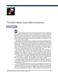
Figure 4 is a block diagram of a fiber-optic antenna<br />
remoting link <strong>for</strong> use in BCAs. In this case, because<br />
GPS is the primary signal of interest, only the receive<br />
function is considered. The primary pieces of inboard<br />
opt<br />
Frequency<br />
Laser<br />
Detector<br />
RF output<br />
312<br />
RF<br />
Frequency<br />
Optical fiber<br />
RF<br />
Frequency<br />
Antenna<br />
Modulator<br />
opt<br />
Frequency<br />
Figure 4. Block diagram of fiber-optic link <strong>for</strong> antenna remoting.<br />
equipment are a laser and photodetector. The laser is<br />
a semiconductor-based component that generates an<br />
optical carrier at a frequency of approximately 193 THz,<br />
indicated by opt in Fig. 4. This unmodulated optical<br />
carrier passes <strong>over</strong> a length of fiber-optic cable with<br />
nearly no attenuation because of the highly transparent<br />
nature of the glass inside the cable. At some distance<br />
away from the laser and inside the BCA, an electrooptic<br />
modulator is used to up-convert the RF signal at<br />
RF from the antenna onto the 193-THz optical carrier.<br />
The modulated carrier is sent back to the photodetector<br />
on a fiber-optic cable. The photodetector is a<br />
square-law device and rec<strong>over</strong>s the original RF signal of<br />
interest. This particular architecture is highly attractive<br />
because the laser and detector are inside the submarine,<br />
with only the modulator outboard. Arranging the components<br />
in this fashion rather than using an outboard<br />
laser reduces the number of active components in the<br />
cable and relaxes outboard thermal design constraints.<br />
In some ways, a fiber-optic link is similar to traditional<br />
RF mixing <strong>for</strong> free space propagation, because<br />
the signal of interest is being up-converted to take<br />
advantage of superior propagation characteristics at the<br />
higher frequency. The down-conversion from optical to<br />
RF takes place at the photodetector. A fiber-optic link<br />
can be treated like a long RF amplifier, in that it has<br />
an RF input and an RF output and can be characterized<br />
by its gain, noise figure, and distortion characteristics.<br />
Compared with conventional electronic links<br />
operating <strong>over</strong> coaxial cable, fiber-optic links can provide<br />
significant advantages in bandwidth, propagation<br />
loss, and weight, as well as immunity to crosstalk and<br />
electromagnetic interference.<br />
Bandwidth and propagation loss can be considered<br />
together, because the signal loss is a function of frequency.<br />
In this area, fiber optics offers superior per<strong>for</strong>mance relative<br />
to coaxial cables. Consider the Times Microwave<br />
LMR-LW400, a flexible, lightweight, low-loss coaxial<br />
cable commonly used <strong>for</strong> GPS remoting applications<br />
that is nominally compatible with BCA mechanical<br />
requirements. 3 The propagation loss of LMR-LW400 at<br />
the principal GPS frequency (1.6 GHz) is 50 dB/1000 ft.<br />
By comparison, the optical loss in a single-mode fiber is<br />
0.06 dB/1000 ft. The actual RF signal loss in optical fiber<br />
is 2 0.06 dB = 0.12 dB/1000 ft, because RF power is<br />
proportional to the square of photocurrent, and photocurrent<br />
is proportional to optical power. For a 2000-ft<br />
BCA (a typical length), the signal loss in this coaxial<br />
cable would be 100 dB, whereas the signal loss in optical<br />
fiber would be only 0.2 dB. This highlights the significant<br />
advantage of fiber optics in antenna remoting <strong>over</strong><br />
extended distances.<br />
To accurately compare optical link per<strong>for</strong>mance to<br />
electrical link per<strong>for</strong>mance, the efficiency of the electrical–optical-electrical<br />
conversion process must be<br />
JOHNS HOPKINS APL TECHNICAL DIGEST, VOLUME 30, NUMBER 4 (2012)