Global Positioning System over Fiber for Buoyant Cable Antennas
Global Positioning System over Fiber for Buoyant Cable Antennas
Global Positioning System over Fiber for Buoyant Cable Antennas

Create successful ePaper yourself
Turn your PDF publications into a flip-book with our unique Google optimized e-Paper software.
<strong>Global</strong> <strong>Positioning</strong> <strong>System</strong> <strong>over</strong> <strong>Fiber</strong><br />
<strong>for</strong> <strong>Buoyant</strong> <strong>Cable</strong> <strong>Antennas</strong><br />
Adil M. Karim, Stephen J. Staf<strong>for</strong>d,<br />
and R. Benjamin Baker<br />
uoyant cable antennas (BCAs) are long, towed antennas used<br />
by submarines to receive RF signals. Deployed while the submarine<br />
is operating at depth, the cable is managed so that the<br />
internal antenna element or elements are positioned near the ocean<br />
surface. The received signal is sent to the submarine <strong>for</strong> processing <strong>over</strong> a transmission<br />
line within the cable. In this article, we examine the design of a fiber-optic signal transport<br />
link <strong>for</strong> a BCA that receives signals from the <strong>Global</strong> <strong>Positioning</strong> <strong>System</strong> (GPS). This<br />
signal and reception method is of significant interest because the resulting GPS solution<br />
can be fused with the submarine’s inertial navigation system to improve <strong>over</strong>all navigation<br />
accuracy without requiring the ship to come to periscope depth.<br />
INTRODUCTION<br />
The evolution of network-centric warfare requires<br />
that submarines have the ability to send and receive<br />
RF signals. Submarines have generally been <strong>for</strong>ced to<br />
come to periscope depth and expose a mast antenna<br />
or deploy a buoy to use the electromagnetic spectrum.<br />
These actions increase detectability and the risk of collision.<br />
However, the development of buoyant cable antennas<br />
(BCAs) has enabled a new mode of operation where<br />
a submarine can remain at depth and still receive RF<br />
signals. This cable contains the active antenna element<br />
or elements as well as the transmission line that carries<br />
the received signal to the submarine <strong>for</strong> processing. The<br />
trailing length of cable is managed using an inboard<br />
deployment system and passes through a seal that maintains<br />
watertight integrity <strong>for</strong> the ship. The focus of this<br />
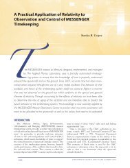
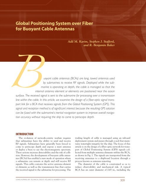
article is on the design of a fiber-optic network <strong>for</strong> transport<br />
of <strong>Global</strong> <strong>Positioning</strong> <strong>System</strong> (GPS) signals collected<br />
from multiple antenna elements within the BCA,<br />
as shown in Fig. 1. The signals are transported from the<br />
receiving antennas to a shipboard location through a<br />
process known as antenna remoting.<br />
The diameter of the cable is constrained so as to<br />
reduce observability and mechanical risk. A typical<br />
BCA has an outer diameter of 0.65 in., including the<br />
JOHNS HOPKINS APL TECHNICAL DIGEST, VOLUME 30, NUMBER 4 (2012) 309
A. KARIM, S. J. STAFFORD, AND R. B. BAKER<br />
310<br />
Sea surface<br />
outer jacket and any internal structure. The maximum<br />
length of any rigid section is 1.0 in., <strong>for</strong> compatibility<br />
with inboard BCA handling equipment. These two factors<br />
severely limit the size of the antenna elements and<br />
supporting electronics. Per<strong>for</strong>mance is further limited<br />
by the ocean surface, which introduces attenuation <strong>for</strong><br />
submerged or partially submerged antennas. In addition,<br />
the conductivity of seawater has a strong impact on the<br />
actual antenna pattern.<br />
The resulting disadvantaged nature of the antenna<br />
and the long length of the cable mean that transport in<br />
the electrical domain is not feasible at higher frequencies.<br />
Even with the use of electronic amplifiers, the substantial<br />
propagation loss increases the noise figure of the<br />
system. Noise figure is a term that measures the degradation<br />
in signal-to-noise ratio (SNR) caused by a component<br />
or system. This increase in noise figure means<br />
that the receiver sensitivity is reduced and that many<br />
signals of interest will not be processed successfully. We<br />
show that <strong>for</strong> cables exceeding a certain length, the use<br />
of fiber optics <strong>for</strong> remoting of received GPS signals offers<br />
a distinct per<strong>for</strong>mance advantage.<br />
GPS OVERVIEW<br />
Historically, submarines have used low-frequency<br />
Long Range Navigation (LORAN) signals to determine<br />
their location and speed. However, this system has been<br />
replaced in recent years by the NAVSTAR GPS. This is<br />
a <strong>Global</strong> Navigation Satellite <strong>System</strong> (GNSS) that provides<br />
worldwide radio c<strong>over</strong>age from a constellation of<br />
<strong>Buoyant</strong><br />
ber-optic cable<br />
GPS links<br />
Figure 1. Submarine with deployed BCA <strong>for</strong> reception of GPS signals.<br />
Antenna<br />
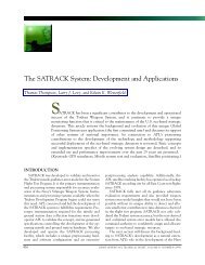
satellites. The satellite constellation consists of at least<br />
24 satellites in medium Earth orbit that transmit a variety<br />
of direct sequence spread spectrum (DSSS) signal<br />
ranging codes, as shown in Fig. 2.<br />
A network of terrestrial control stations provides the<br />
satellites with accurate time and position in<strong>for</strong>mation.<br />
This in<strong>for</strong>mation is encoded in the signals transmitted<br />
by the GPS satellites, enabling users on the ground to<br />
extract the propagation time from the satellite to the<br />
Figure 2. GPS satellite constellation in medium Earth orbit.<br />
JOHNS HOPKINS APL TECHNICAL DIGEST, VOLUME 30, NUMBER 4 (2012)
eceiving antenna by demodulating the received signal.<br />
This propagation time can be used to estimate a pseudorange,<br />
an estimate of the distance from the antenna to<br />
an individual satellite. The pseudo-range, i , to the i th<br />
satellite is given by<br />
i = |P – P i | + cT , (1)<br />
where P is the user’s position, P i is the i th satellite’s position,<br />
c is the speed of light, and T is the error contribution<br />
from the receiver’s clock. Equation 1 would be used<br />
to determine the user’s position once sufficient pseudorange<br />
in<strong>for</strong>mation has been obtained.<br />
The GPS system transmits several DSSS ranging<br />
signals, the most important of which are the civilian<br />
Coarse Acquisition (C/A) signal centered at the L1 frequency<br />
(1575.42 MHz) and the two military Precision<br />
P(Y) signals centered at the L1 and L2 (1227.60 MHz)<br />
frequencies. The P refers to a precision signal with<br />
greater accuracy than the C/A signal, and P(Y) refers to<br />
the encrypted version of this signal. For the purposes of<br />
this article, the principal difference between the civilian<br />
and military signals is their bandwidth. The C/A<br />
signal has a bandwidth of 2.046 MHz, and the P(Y)<br />
signal has a bandwidth of 20.46 MHz. In addition to<br />
the ranging signal, each satellite transmits a navigation<br />
message including clock corrections and almanac and<br />
ephemeris in<strong>for</strong>mation. The clock corrections, almanac<br />
in<strong>for</strong>mation, and ephemeris in<strong>for</strong>mation are required<br />
to synchronize the satellite atomic clocks with terrestrial<br />
receiver clocks. The almanac message contains<br />
coarse orbit in<strong>for</strong>mation <strong>for</strong> all satellites in the constellation<br />
and can be used to determine which satellites<br />
are within the receiver’s field of view. This reduces the<br />
receiver search time. The ephemeris message contains<br />
precise orbit in<strong>for</strong>mation <strong>for</strong> the individual satellite.<br />
This orbital in<strong>for</strong>mation is required to minimize errors<br />
resulting from minor variations in the satellite’s orbit.<br />
The ephemeris data are valid <strong>for</strong> only a few hours and<br />
must be updated periodically. A position is calculated<br />
through trilateration, which requires pseudo-ranges<br />
from at least four satellites in a<br />
nondegenerate geometry to solve<br />
<strong>for</strong> the user’s four unknowns:<br />
latitude, longitude, altitude, and<br />
receiver clock error. Pseudo-range<br />
measurements from additional<br />
satellites improve the geometry<br />
and allow integrity monitoring. 1<br />
GPS SIGNAL RECEPTION<br />
IN BCAs<br />
The principal difficulty with<br />
GPS signal reception <strong>over</strong> the<br />
Elevation (m)<br />
0<br />
–0.2<br />
–0.4<br />
GPS OVER FIBER FOR BUOYANT CABLE ANTENNAS<br />
BCA is attenuation along the RF signal path. This<br />
includes propagation through the atmosphere, potential<br />
propagation through seawater, antenna gain that is<br />
limited by the BCA geometry, and, finally, propagation<br />
along the BCA transmission line to the GPS receiver.<br />
The GPS signal level <strong>for</strong> antennas at or slightly above<br />
the ocean surface is approximately –130 dBm, where<br />
dBm refers to the power ratio in decibels relative to<br />
1 mW. Over the sampled bandwidth of the C/A signal<br />
(2.046 MHz), the integrated thermal noise is approximately<br />
–111 dBm. For an antenna gain of 0 dBi, this<br />
means that the SNR at the antenna is –19 dB. The term<br />
dBi refers to the gain of the antenna under consideration<br />
(in decibels) compared to that of an isotropic antenna,<br />
which radiates uni<strong>for</strong>mly in all directions. Although this<br />
number seems low, a significant amount of processing<br />
gain (43 dB) can be achieved by despreading the DSSS<br />
signal. For a target sensitivity of –140 dBm (providing<br />
10 dB of link margin), the SNR at the antenna is –29 dB.<br />
This 10 dB of link margin can be used to compensate<br />
<strong>for</strong> propagation losses or accommodate antenna detuning<br />
caused by the ocean surface. A typical GPS receiver<br />
requires an SNR of 10 dB after despreading, which is<br />
equivalent to an SNR of –33 dB prior to despreading.<br />
Comparing the SNR at the antenna with the required<br />
SNR, we see that the antenna and receive link can only<br />
degrade the SNR by 4 dB be<strong>for</strong>e the received signal<br />
becomes unusable. The penalty caused to the SNR by<br />
a component or subsystem is known as the noise figure,<br />
expressed in decibels. On the basis of this calculation,<br />
the GPS BCA receive path must have a noise figure of<br />
less than 4 dB. The numbers provided here are approximate<br />
values, but they do indicate that the BCA receive<br />
link must have a low noise figure nearly equal to that of<br />
conventional GPS receive links, which need to operate<br />
<strong>over</strong> only a short length of cable.<br />
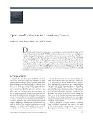
Receiving GPS signals <strong>over</strong> a BCA is further complicated<br />
by the operating environment, shown in Fig. 3.<br />
The antenna is presented with two obstacles: seawater<br />
wash<strong>over</strong> and cable roll that can align the antennas<br />
downward. Even mild antenna wash<strong>over</strong> rapidly attenu-<br />
Wire<br />
Antenna elements<br />
–0.6<br />
35 40 45 50<br />
Along-track range (m)<br />
Figure 3. BCA floating on ocean surface. Some antenna elements are submerged or partially<br />
submerged.<br />
JOHNS HOPKINS APL TECHNICAL DIGEST, VOLUME 30, NUMBER 4 (2012) 311<br />
55
A. KARIM, S. J. STAFFORD, AND R. B. BAKER<br />
ates GPS signals—the attenuation of RF at L1 in seawater<br />
is more than 1000 dB/m. 2 These impediments can<br />
be <strong>over</strong>come through redundancy. The proposed system<br />
consists of 12 GPS antennas separated by 8–10 ft each<br />
along the cable. Each antenna is capable of independently<br />
receiving GPS signals, and this approach prevents<br />
a single wave from washing <strong>over</strong> the entire array.<br />
In addition, the antennas are aligned at offset angles of<br />
120° with respect to each other along the length of the<br />
cable. This mitigates the antenna per<strong>for</strong>mance degradation<br />
caused by uncertain roll of the cable and eliminates<br />
the possibility of all antenna elements being oriented<br />
downward. This rotation pattern repeats <strong>for</strong> each of the<br />
four sets of three antennas. The antennas used during<br />
system development were tuned to a 2-MHz bandwidth<br />
to collect the C/A signal. We anticipate that future versions<br />
of this antenna will have a wider bandwidth to<br />
support collection of the P(Y) signal.<br />
In-water testing of the BCA indicates that a single<br />
antenna can successfully collect brief segments of GPS<br />
signals between waves as the antennas go in and out<br />
of the water. For sea states 2–3, the typical segment<br />
duration was on the order of 100 ms, and the duration<br />
of the GPS dropouts was of the same magnitude.<br />
While above water, the carrier-to-noise density ratio<br />
was 30–35 dB-Hz, which is sufficient to provide a high<br />
probability of signal detection. The signal segments are<br />
frequent enough that closed-loop delay-locked loops<br />
can support clock and data rec<strong>over</strong>y despite the intermittent<br />
signal, which allows the successful extraction<br />
of pseudo-range values. However, obtaining a phase<br />
lock and estimating carrier phase from a single element<br />
under these conditions is not possible. Inboard processing<br />
is discussed in more detail in the GPS Signal<br />
Processing section.<br />
FIBER OPTICS FOR ANTENNA REMOTING<br />
Figure 4 is a block diagram of a fiber-optic antenna<br />
remoting link <strong>for</strong> use in BCAs. In this case, because<br />
GPS is the primary signal of interest, only the receive<br />
function is considered. The primary pieces of inboard<br />
opt<br />
Frequency<br />
Laser<br />
Detector<br />
RF output<br />
312<br />
RF<br />
Frequency<br />
Optical fiber<br />
RF<br />
Frequency<br />
Antenna<br />
Modulator<br />
opt<br />
Frequency<br />
Figure 4. Block diagram of fiber-optic link <strong>for</strong> antenna remoting.<br />
equipment are a laser and photodetector. The laser is<br />
a semiconductor-based component that generates an<br />
optical carrier at a frequency of approximately 193 THz,<br />
indicated by opt in Fig. 4. This unmodulated optical<br />
carrier passes <strong>over</strong> a length of fiber-optic cable with<br />
nearly no attenuation because of the highly transparent<br />
nature of the glass inside the cable. At some distance<br />
away from the laser and inside the BCA, an electrooptic<br />
modulator is used to up-convert the RF signal at<br />
RF from the antenna onto the 193-THz optical carrier.<br />
The modulated carrier is sent back to the photodetector<br />
on a fiber-optic cable. The photodetector is a<br />
square-law device and rec<strong>over</strong>s the original RF signal of<br />
interest. This particular architecture is highly attractive<br />
because the laser and detector are inside the submarine,<br />
with only the modulator outboard. Arranging the components<br />
in this fashion rather than using an outboard<br />
laser reduces the number of active components in the<br />
cable and relaxes outboard thermal design constraints.<br />
In some ways, a fiber-optic link is similar to traditional<br />
RF mixing <strong>for</strong> free space propagation, because<br />
the signal of interest is being up-converted to take<br />
advantage of superior propagation characteristics at the<br />
higher frequency. The down-conversion from optical to<br />
RF takes place at the photodetector. A fiber-optic link<br />
can be treated like a long RF amplifier, in that it has<br />
an RF input and an RF output and can be characterized<br />
by its gain, noise figure, and distortion characteristics.<br />
Compared with conventional electronic links<br />
operating <strong>over</strong> coaxial cable, fiber-optic links can provide<br />
significant advantages in bandwidth, propagation<br />
loss, and weight, as well as immunity to crosstalk and<br />
electromagnetic interference.<br />
Bandwidth and propagation loss can be considered<br />
together, because the signal loss is a function of frequency.<br />
In this area, fiber optics offers superior per<strong>for</strong>mance relative<br />
to coaxial cables. Consider the Times Microwave<br />
LMR-LW400, a flexible, lightweight, low-loss coaxial<br />
cable commonly used <strong>for</strong> GPS remoting applications<br />
that is nominally compatible with BCA mechanical<br />
requirements. 3 The propagation loss of LMR-LW400 at<br />
the principal GPS frequency (1.6 GHz) is 50 dB/1000 ft.<br />
By comparison, the optical loss in a single-mode fiber is<br />
0.06 dB/1000 ft. The actual RF signal loss in optical fiber<br />
is 2 0.06 dB = 0.12 dB/1000 ft, because RF power is<br />
proportional to the square of photocurrent, and photocurrent<br />
is proportional to optical power. For a 2000-ft<br />
BCA (a typical length), the signal loss in this coaxial<br />
cable would be 100 dB, whereas the signal loss in optical<br />
fiber would be only 0.2 dB. This highlights the significant<br />
advantage of fiber optics in antenna remoting <strong>over</strong><br />
extended distances.<br />
To accurately compare optical link per<strong>for</strong>mance to<br />
electrical link per<strong>for</strong>mance, the efficiency of the electrical–optical-electrical<br />
conversion process must be<br />
JOHNS HOPKINS APL TECHNICAL DIGEST, VOLUME 30, NUMBER 4 (2012)
considered along with the fiber-optic propagation loss.<br />
The inefficiency of this process limits fiber-optic link<br />
gain, which sets a lower limit on link noise figure. The<br />
fiber-optic link noise figure can be further degraded by<br />
laser relative intensity noise and shot noise from the<br />
photodetection process. Assume that a low-noise electrical<br />
amplifier with a gain of 60 dB and a noise figure<br />
of 2 dB is available <strong>for</strong> use between the antenna and the<br />
coaxial transmission line or between the antenna and<br />
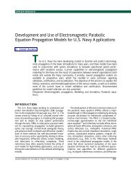
the electro-optic modulator. Figure 5 shows the link<br />
noise figure as a function of distance <strong>for</strong> frequencies<br />
of 1.6 GHz in LMR-LW400 and through a fiber-optic<br />
link. The calculated noise figure of the fiber-optic link<br />
is based on COTS components and includes conversion<br />
efficiency, propagation loss, and the additive noise<br />
factors discussed above. The same comparison is made<br />
at 10 and 20 GHz. Although these frequencies are not<br />
used <strong>for</strong> GPS, they are of interest <strong>for</strong> future BCA applications<br />
and are included here to illustrate per<strong>for</strong>mance<br />
at higher frequencies and the scalability of a fiber-optic<br />
BCA. For the GPS signal, the fiber-optic link has a<br />
lower noise figure than the coaxial link <strong>for</strong> distances<br />
greater than 800 ft. The cross<strong>over</strong> distances <strong>for</strong> 10 and<br />
20 GHz are 300 and 200 ft, respectively. For a distance<br />
of 2000 ft, the cross<strong>over</strong> frequency at which the fiberoptic<br />
link has a lower noise figure is approximately<br />
300 MHz. The noise figures of the fiber-optic links are<br />
slightly greater than 2 dB as a consequence of inefficiencies<br />
in the electrical–optical–electrical conversion<br />
Noise gure (dB)<br />
20<br />
15<br />
10<br />
5<br />
0 0 500 1000 1500<br />
Distance (ft)<br />
GPS OVER FIBER FOR BUOYANT CABLE ANTENNAS<br />
process, photodetector shot noise, and relative intensity<br />
noise from the laser. Additional background on analog<br />
fiber-optic link per<strong>for</strong>mance and design methods is<br />
available in Refs. 4–6.<br />
In theory, it is possible to use multiple electrical<br />
amplifiers to reduce the noise figure of the electrical link.<br />
However, this approach has severe disadvantages. The<br />
additional active components increase complexity and<br />
power consumption while reducing reliability. From an<br />
RF perspective, increasing the amplifier count reduces<br />
the dynamic range and input power damage threshold.<br />
Down-conversion of the received GPS signal to a lower<br />
intermediate frequency is another possible option, but<br />
this option still requires a high degree of outboard component<br />
complexity, including active components.<br />
Weight is an important factor because the BCA must<br />
be nearly neutrally buoyant <strong>for</strong> the trailing antenna to<br />
reside at or above the surface during operation. The<br />
weight per unit length of a fiber-optic cable is typically<br />
much lower than that of a coaxial cable, particularly<br />
when both cables are inside the protective BCA jacket.<br />
The coaxial cable considered above, Times Microwave<br />
LMR-LW400, has a weight of 50 lb per 1000 ft of cable.<br />
In contrast, a standard single-mode fiber with a protective<br />
coating has a weight of 1 lb per 1000 ft. For a 2000-ft<br />
BCA, the total weight savings are approximately 98 lb<br />
without any loss in capability. Another view would be<br />
that <strong>for</strong> the same weight allocation, additional fibers<br />
can be installed to improve system scalability or provide<br />
additional functionality.<br />
For example, the additional<br />
1.6 GHz, coaxial<br />
10 GHz, coaxial<br />
20 GHz, coaxial<br />
1.6 GHz, ber<br />
10 GHz, ber<br />
20 GHz, ber<br />
2000 2500 3000<br />
Figure 5. Noise figure comparison between optical fiber and coaxial cable at frequencies of<br />
1.6, 10, and 20 GHz.<br />
fibers could support future<br />
system expansion or provide<br />
redundancy in case of a<br />
fiber break, antenna failure,<br />
or electronics failure. This<br />
is impossible with a BCA<br />
containing a single conventional<br />
coaxial cable.<br />
Because sea states and<br />
wave conditions vary, it is<br />
difficult to guarantee that a<br />
single antenna element in a<br />
BCA will be at, rather than<br />
below, the surface. Thus it is<br />
highly desirable to use multiple<br />
antenna elements and<br />
process the received signals<br />
from each of them. 7 When<br />
remoting multiple antennas<br />
in a constrained space such<br />
as a BCA, electromagnetic<br />
interference and crosstalk<br />
can be significant in conductive<br />
cables. Because a<br />
JOHNS HOPKINS APL TECHNICAL DIGEST, VOLUME 30, NUMBER 4 (2012) 313
A. KARIM, S. J. STAFFORD, AND R. B. BAKER<br />
Laser<br />
Laser<br />
Laser<br />
Laser<br />
fiber-optic cable is all-dielectric, it is immune to electromagnetic<br />
interference and to crosstalk from adjacent<br />
fibers. Furthermore, a single fiber-optic line can be used<br />
to carry numerous RF signals at identical or different<br />
frequencies using multiple optical carriers in a technique<br />
known as wavelength-division multiplexing. 8<br />
In this architecture, passive optical elements with low<br />
insertion loss are used to multiplex, filter, and demultiplex<br />
modulated optical carriers with negligible levels<br />
of crosstalk between the various signals. An example is<br />
shown in Fig. 6. Four lasers at different wavelengths are<br />
combined using a 4 1 multi plexer so that the output<br />
can be carried on a single optical fiber. At an intermediate<br />
point in the system, one wavelength is dropped<br />
from the stream using a narrowband optical filter. This<br />
wavelength is then modulated with an RF signal and<br />
added back to the stream using a second optical filter.<br />
The four-wavelength stream, with a single modulated<br />
wavelength, is then demultiplexed, with each wavelength<br />
going to a different photodetector. The crosstalk<br />
between the electrical outputs from each photodetector<br />
is generally better than –60 dB and can be better<br />
than –80 dB. These values are more than sufficient<br />
<strong>for</strong> successful electronic demultiplexing of the received<br />
signal. The passive optical filters described here are key<br />
elements in enabling a BCA system architecture that is<br />
robust and scalable.<br />
BCA SYSTEM DESIGN<br />
On the basis of the noise figure analysis described<br />
in the preceding section, as well as the other advantages<br />
of optical networks, a fiber-optic backbone is the<br />
proper design choice <strong>for</strong> higher-frequency (>300 MHz)<br />
BCA systems. Although the emphasis of this design is<br />
the reception of GPS signals,<br />
an additional goal is to provide<br />
a backbone that can scale to<br />
higher frequencies of interest.<br />
This backbone can consist of<br />
one fiber or multiple fibers. Consider<br />
the case where the BCA<br />
contains 12 individual antenna<br />
elements. These elements could<br />
be remoted by two fibers using<br />
314<br />
M<br />
U<br />
X<br />
Drop Add<br />
Modulator<br />
Detector<br />
Detector<br />
Detector<br />
Detector<br />
Figure 6. Wavelength division multiplexing using passive optical<br />
components. DEMUX, demultiplexer; MUX, multiplexer.<br />
D<br />
E<br />
M<br />
U<br />
X<br />
Shipboard<br />
12 optical carriers<br />
12 wavelengths, as shown in Fig. 7. One fiber would<br />
be used to transmit 12 unmodulated optical carriers,<br />
while 12 modulated optical carriers would return on the<br />
second fiber. However, the fiber plant itself would be a<br />
single point of failure in this architecture, since damage<br />
to the fiber or an optical filter could disable the entire<br />
system. Redundancy can be provided by using multiple<br />
fibers. Using 12 fiber pairs would provide full independence<br />
between antenna elements but would have a high<br />
degree of mechanical complexity. An intermediate<br />
number of fiber pairs, such as four, can be used to provide<br />
some redundancy without the challenges of a fully independent<br />
remoting architecture. This preferred option<br />
is illustrated in Fig. 8. Note that the use of 12 separate<br />
antenna elements also provides some degree of redundancy,<br />
because any one antenna is capable of receiving<br />
a GPS signal. Overall availability would be reduced if<br />
fewer than 12 antenna elements were accessible, but<br />
limited functionality would still be available. Additional<br />
details on the availability of individual elements and the<br />
<strong>over</strong>all system concept are given elsewhere. 7<br />
An additional constraint on the number of fibers is<br />
imposed by the requirement to use fiber-optic terminations<br />
between sections to support modular replacement<br />
and future expansion. Commercially available terminations<br />
that meet <strong>for</strong>m-factor requirements support a maximum<br />
of 12 fibers. Four wavelengths are used <strong>for</strong> each<br />
of the four fiber pairs, with the appropriate drop and<br />
add filters at each antenna element. These wavelengths<br />
are indicated by the colors red, orange, green, and blue<br />
in Fig. 8. The wavelengths are staggered so that each<br />
module is identical and could be replaced by a universal<br />
spare. Using three wavelengths <strong>for</strong> active remoting on<br />
each of the four fiber pairs leaves one wavelength per<br />
fiber pair unused. The additional wavelength can be<br />
used <strong>for</strong> future expansions by simply connecting an additional<br />
antenna module. This expansion capability can<br />
support additional GPS antenna modules or a different<br />
type of antenna module.<br />
For this antenna remoting architecture, multiple<br />
optical carriers are generated inboard using semiconductor<br />
lasers. The outputs of semiconductor lasers are<br />
horizontally polarized. The optical modulators used in<br />
the outboard portion of the BCA respond efficiently<br />
only when used with horizontally polarized light. Ordi-<br />
1 1 1 1 1 1 1 1 1 1<br />
1 2 3 4 12<br />
Figure 7. BCA with a single fiber pair. The fiber plant is a single point of failure.<br />
JOHNS HOPKINS APL TECHNICAL DIGEST, VOLUME 30, NUMBER 4 (2012)
Shipboard<br />
narily, the horizontal polarization could be maintained<br />
<strong>over</strong> the length of the BCA by using polarization-<br />
maintaining fiber. However, the requirement to use<br />
optical terminations between sections of the outboard<br />
cable eliminates this possibility. There are no commercially<br />
available multiple-fiber terminations that<br />
maintain polarization across the termination, although<br />
there are terminations available that support 12 standard<br />
fibers. The cost of polarization-maintaining fiber<br />
is also much greater than that of standard fiber. As a<br />
result, an alternative method of delivering horizontally<br />
polarized light to the modulator <strong>over</strong> standard fiber<br />
was required. In a standard fiber, the polarization state<br />
varies based on temperature, mechanical stress, and<br />
other environmental conditions. A concept developed<br />
<strong>for</strong> this project was to use a dual-polarization optical<br />
carrier consisting of two closely spaced, orthogonally<br />
polarized optical wavelengths. The two wavelengths<br />
are closely spaced so that they see the same polarization<br />
rotations as they propagate through standard fiber.<br />
An in-fiber polarizer is used prior to the modulator that<br />
scatters vertically polarized light and passes horizontally<br />
polarized light. Half of the source light is lost, but<br />
a horizontally polarized component of constant magnitude<br />
is always delivered to the modulator. This architecture<br />
is illustrated in Fig. 9 <strong>for</strong> two example scenarios.<br />
Even though the amount of polarization rotation in<br />
the standard fiber varies, the two components remain<br />
orthogonal. The final composition of the horizontal<br />
Transmitter<br />
Rotation<br />
Standard<br />
fiber<br />
4 4 4 4 4 4<br />
44 44 optical carriers 1–4 5–8 9–12<br />
Figure 8. BCA with wavelength-division multiplexing and extra fiber pairs <strong>for</strong> redundancy.<br />
Polarizing<br />
fiber<br />
Constant total<br />
horizontal<br />
component<br />
Modulator<br />
Figure 9. Polarization rotation of transmitted carrier components<br />
and selection of horizontal component by polarizing fiber.<br />
Even though the amount of rotation varies in the two cases<br />
shown, a total horizontal component of constant magnitude is<br />
delivered to the modulator.<br />
GPS OVER FIBER FOR BUOYANT CABLE ANTENNAS<br />
component delivered to the<br />
modulator changes, but its magnitude<br />
is constant. The remaining<br />
passive components in the<br />
optical path are not polarization<br />
sensitive, so no additional<br />
polarization management is<br />
required. When the two modulated<br />
components are incident<br />
on the photodiode, the RF<br />
output signals from each indi-<br />
vidual wavelength are summed. For a given input signal,<br />
this ensures a constant output signal level <strong>over</strong> varying<br />
cable conditions.<br />
The frequency spacing between the two wavelengths<br />
used to generate the composite carrier is an interesting<br />
point <strong>for</strong> discussion. If the two source wavelengths<br />
were very closely spaced (10 GHz) but is still worth considering because<br />
the fiber plant should support future growth. If the two<br />
wavelengths were too far apart (>400 GHz), the polarization<br />
variation would not be constant across this span<br />
and there would be no guarantee that a horizontally<br />
polarized component would be delivered to the in-fiber<br />
polarizer or the modulator. An intermediate spacing<br />
of 200 GHz was chosen to meet per<strong>for</strong>mance requirements<br />
and simplify component selection. At this spacing,<br />
there are no concerns about interference effects at<br />
the photodiode.<br />
For the initial engineering demonstration, a BCA<br />
system containing three antenna nodes was designed<br />
and assembled. This small-scale demonstration was<br />
intended as a proof-of-concept <strong>for</strong> the larger 12-node<br />
system. The number of nodes and optical carriers used<br />
was reduced relative to the 12-node design, but the basic<br />
functionality and architecture are identical. <strong>System</strong><br />
details are provided here <strong>for</strong> the three-node engineering<br />
demonstration model. The composite optical carriers<br />
are designated in Fig. 10 by l1±, l2±, and l3±.<br />
The actual system uses two fiber pairs that each carry<br />
three composite carriers. For clarity, Fig. 10 shows only<br />
a single fiber pair from Fig. 9. The remaining fiber pairs<br />
are identical (except <strong>for</strong> the staggered wavelength plan)<br />
and include redundant inboard hardware. From an optical<br />
perspective, the BCA consists of four independent<br />
two-fiber networks, each carrying four wavelengths.<br />
Each two-fiber network can be extended by using the<br />
fourth reserved wavelength or simply adding more<br />
wavelengths. The composite carriers are combined on<br />
a single fiber using an optical multiplexer. An optical<br />
amplifier (not shown) is used to boost the optical carrier<br />
levels prior to entering the outboard portion of the<br />
JOHNS HOPKINS APL TECHNICAL DIGEST, VOLUME 30, NUMBER 4 (2012) 315
A. KARIM, S. J. STAFFORD, AND R. B. BAKER<br />
Source lasers<br />
1± 2± 3±<br />
BCA. An inboard patch cable is used to connect the<br />
amplifier output to the transmission line. The transmission<br />
line passes through a fiber-optic rotary joint and<br />
the ship’s handling gear be<strong>for</strong>e exiting the submarine.<br />
Electrical-to-optical conversion takes place at the block<br />
labeled E/O, and optical-to-electrical conversion takes<br />
place at the block labeled O/E.<br />
A detailed illustration of the antenna node is shown<br />
in Fig. 11. At the first antenna node, the first carrier<br />
(orange) is dropped <strong>for</strong> modulation. A standard thin-film<br />
optical filter is used to drop the carrier of interest while<br />
allowing the other two carriers to pass through. Both<br />
the drop and the through paths have low insertion loss<br />
of less than 0.7 dB each. The polarization state of the<br />
carrier has changed after passing through the fiber but<br />
still consists of two orthogonal components. A polarizing<br />
fiber passes the horizontal component of the carrier<br />
and scatters the vertical component. The carrier is then<br />
modulated using a lithium niobate Mach–Zehnder modulator<br />
(the E/O modulator in Fig. 11). This is a common<br />
modulator type <strong>for</strong> RF and microwave applications. The<br />
modulator used in this project<br />
is reflective, meaning<br />
that input (unmodulated)<br />
and output (modulated)<br />
fibers are on the same side<br />
of the device. A bias controller<br />
is used to maintain<br />
an optimal operating point<br />
<strong>for</strong> the electro-optic modulator.<br />
This controller generates<br />
a low-frequency pilot<br />
tone and monitors an internal<br />
modulator photodiode<br />
316<br />
MUX<br />
Shipboard<br />
DEMUX<br />
O/E converters<br />
Signal conditioning<br />
GPS receivers<br />
Optical<br />
connector<br />
Node 1 Node 2 Node 3<br />
Drop<br />
Drop Drop<br />
GPS antenna<br />
1 2 3<br />
E/O E/O E/O<br />
Amplifier<br />
Add Add Add<br />
Optical<br />
connector<br />
Polarizing<br />
fiber<br />
Optical<br />
connector<br />
<strong>Cable</strong><br />
Figure 10. Block diagram of BCA optical network. A single fiber pair is shown <strong>for</strong> clarity. The actual<br />
network consists of four such fiber pairs with a staggered wavelength plan. E/O, electrical-to-optical<br />
conversion; O/E, optical-to-electrical conversion.<br />
as part of a feedback control<br />
loop. The GPS signal<br />
received by the antenna<br />
is amplified be<strong>for</strong>e reaching<br />
the optical modulator.<br />
The purpose of this amplifier<br />
chain is to set the noise<br />
figure of the <strong>over</strong>all link by<br />
compensating <strong>for</strong> the losses<br />
and the additive noise of<br />
the fiber-optic portion.<br />
A second filter is used to<br />
return the modulated carrier<br />
to the multiple-wavelength<br />
stream. The components<br />
are spaced along the cable<br />
in individual housings to<br />
meet the diameter and rigidlength<br />
constraints.<br />
The modulated carriers<br />
return to the submarine on<br />
the second fiber, as shown in Fig. 10, and pass through<br />
the handling gear. A second optical amplifier with<br />
variable gain is used to compensate <strong>for</strong> variable loss<br />
levels in the fiber-optic rotary joint as the deployed<br />
cable length is increased or decreased. The carriers are<br />
then demultiplexed, with each composite carrier being<br />
routed to a photodetector. The electrical output from<br />
each photodetector is the sum of the two modulated<br />
carrier components, as described above. This approach<br />
eliminates fading and guarantees a constant signal level<br />
<strong>over</strong> varying polarization conditions. The electrical<br />
outputs from the photodetectors (O/E in Fig. 10), which<br />
consist of the received GPS signals plus gain and noise<br />
from the link, are passed to inboard processing units<br />
<strong>for</strong> signal conditioning and demodulation. This process<br />
repeats at the other two nodes at different wavelengths.<br />
FIBER-OPTIC LINK PERFORMANCE<br />
The noise figure is the key figure of merit in evaluating<br />
GPS link per<strong>for</strong>mance. For the GPS signal to be suc-<br />
<strong>Fiber</strong> optics, outbound<br />
Drop Add Bias controller E/O modulator Amplifiers<br />
<strong>Fiber</strong> optics, return<br />
Figure 11. Detailed illustration of antenna node architecture.<br />
GPS antenna<br />
Optical<br />
Electrical<br />
JOHNS HOPKINS APL TECHNICAL DIGEST, VOLUME 30, NUMBER 4 (2012)
cessfully demodulated, the noise figure of the electrically<br />
pre-amplified fiber-optic link is specified to be less than<br />
3.0 dB, providing 1 dB of margin against the 4-dB figure<br />
mentioned earlier. The noise figure <strong>for</strong> the optical portion<br />
of the link is determined by laser noise, optical amplifier<br />
noise, modulator efficiency, and the received photocurrent<br />
level. 4 Recent advances in component design and<br />
novel link architectures have resulted in fiber-optic links<br />
with noise figures of less than 10.0 dB without electrical<br />
pre-amplification. 5, 6, 9 However, the constraints on rigid<br />
length in the BCA severely limit modulator efficiency.<br />
As a result, the BCA fiber-optic link has a gain of –36 dB<br />
and a noise figure of 42 dB at 1.6 GHz. This is comparable<br />
to the per<strong>for</strong>mance level that would be expected<br />
using a standard commercial fiber-optic link, but in a<br />
much more challenging geometry.<br />
Considering the fiber-optic link noise figure of<br />
42 dB, a significant amount of electrical pre-amplification<br />
is required to reduce the <strong>over</strong>all link noise figure<br />
to less than 3 dB. Because GPS adoption has been so<br />
widespread, there are a number of high-per<strong>for</strong>mance,<br />
low-noise amplifiers to choose from. Many parts have<br />
noise figures of less than 1.0 dB. For this application,<br />
a three-stage amplifier with a total gain of 50 dB and<br />
a noise figure of 1.5 dB was assembled using commercially<br />
available components. The gain stages are separated<br />
physically as shown in Fig. 11, both to prevent<br />
oscillation and to meet BCA rigid-length constraints.<br />
The first stage is integrated directly with the antenna to<br />
limit front-end losses.<br />
Cascade analysis can be used to calculate the <strong>over</strong>all<br />
link noise figure. Because of the large amount of<br />
low-noise gain prior to electro-optic modulation, the<br />
combined link has a gain of 14 dB and a noise figure<br />
of 1.9 dB. The gain and noise figure <strong>for</strong> the electrical<br />
preamplifiers, the fiber optics, and the combined link<br />
are summarized in Table 1. This link budget includes<br />
realistic component values and cable loss between<br />
components.<br />
The calculated link noise figure of 1.9 dB is lower<br />
than the 4 dB requirement estimated above (see the<br />
GPS Signal Reception in BCAs section) and provides<br />
some additional margin against unexpected losses and<br />
component degradation. This low noise figure is a necessary<br />
but not sufficient condition <strong>for</strong> successful processing<br />
of the GPS signal.<br />
Table 1. Cascaded noise figure <strong>for</strong> GPS <strong>over</strong> fiber link<br />
Subsystem Gain (dB) Noise figure (dB)<br />
Electrical 50.0 1.5<br />
Optical –36.0 42.0<br />
Total 14.0 1.9<br />
GPS OVER FIBER FOR BUOYANT CABLE ANTENNAS<br />
GPS SIGNAL PROCESSING<br />
The GPS ranging codes are <strong>over</strong>laid with a BPSK<br />
(binary phase shift keying) navigation message at a<br />
data rate of 50 bits/s. This message contains necessary<br />
in<strong>for</strong>mation <strong>for</strong> accurate positioning (see the GPS<br />
Overview section) and must be decoded from each<br />
satellite individually. Each message frame contains<br />
1500 bits and has a duration of 30 s. The clock correction<br />
and ephemeris in<strong>for</strong>mation are included in<br />
each message frame and repeat every 30 s. The almanac<br />
in<strong>for</strong>mation is distributed <strong>over</strong> 25 message frames.<br />
The demodulation process is complicated by the fact<br />
that the received GPS signal levels from the BCA rise<br />
and fall with a period of approximately 100 ms due to<br />
wave action. During the strong signal portions, the<br />
GPS message can be demodulated. A reconstruction<br />
algorithm can be used to fuse the handful of bits that<br />
are demodulated from each segment. The combining<br />
algorithm leverages the 30-s repetition of the message<br />
and the <strong>for</strong>ward error correction within the message to<br />
combine the demodulated bits across the antennas. A<br />
voting scheme uses the probability of bit error to favor<br />
bits from strong signals. Hardware-in-the-loop tests<br />
in the Chesapeake Bay indicate that this approach<br />
is capable of decoding the message in an acceptable<br />
amount of time.<br />
This system differs from conventional GPS systems<br />
in that the signals are received on an array of 12 antennas.<br />
The pseudo-range model from Eq. 1 is generalized<br />
<strong>for</strong> the multi-antenna system to include an antenna<br />
index j:<br />
i = |P j – P i | + cT + cT j , (2)<br />
where i is the range to the i th satellite, P j is the location<br />
of the j th antenna, P i is the position of satellite<br />
i, T is the receiver clock error, and T j is the propagation<br />
delay from the j th antenna to the receiver. The<br />
antenna-specific delay T j includes the propagation<br />
through the BCA to the receiver on the submarine.<br />
This delay can be directly characterized during assembly<br />
by using a network analyzer or can be calculated using<br />
the cable length and group delay of individual components.<br />
Likewise, the offset of each antenna relative to<br />
the first antenna can be predicted. This offset can be<br />
estimated through knowledge of the relative distance<br />
between the antennas along the BCA and the BCA’s<br />
orientation, which is known from the inertial navigation<br />
system aboard the submarine. The correction <strong>for</strong><br />
the offset can then be applied to the measurements from<br />
antennas 2 through 12. With knowledge of the relative<br />
propagation delays and position offsets, Kalman filtering<br />
and other signal processing techniques can be used<br />
to extract a composite GPS solution from the (up to)<br />
12 independently received GPS signals.<br />
JOHNS HOPKINS APL TECHNICAL DIGEST, VOLUME 30, NUMBER 4 (2012) 317
A. KARIM, S. J. STAFFORD, AND R. B. BAKER<br />
ACCURACY OF THE GPS MEASUREMENTS<br />
Reconstructing the GPS navigation message from<br />
intermittently received signals is the primary challenge<br />
<strong>for</strong> this BCA system. Once the signals have been<br />
received, stitched together, and demodulated, the noise<br />
sources and <strong>over</strong>all accuracy <strong>for</strong> each received signal can<br />
be analyzed in the same manner used in more conventional<br />
GPS systems. The pseudo-range measurements<br />
described in Eq. 2 have several sources of noise, including<br />
receiver measurement noise, satellite positioning and<br />
timing errors, atmospheric delays, and multipath errors.<br />
The pseudo-range noise maps directly into positioning<br />
error through the dilution-of-precision multiplier. The<br />
dilution-of-precision multiplier converts pseudo-range<br />
uncertainty to position uncertainty and is between<br />
1 and 5 <strong>for</strong> most applications.<br />
Receiver noise is a random measurement error and a<br />
function of the carrier-to-noise ratio C/N 0 . This thermal<br />
noise–dominated error is well approximated by Eq. 3:<br />
c<br />
B<br />
1<br />
2<br />
RCVR = <br />
2CN<br />
/ c +<br />
^ h T C/ N<br />
318<br />
0 CO 0<br />
m (meters), (3)<br />
where s RCVR is the receiver noise error, t is the chipping<br />
period of the DSSS signal, B is the tracking loop<br />
bandwidth, T CO is the integration time, and C/N 0 is the<br />
signal strength in linear units. This expression applies to<br />
delay lock loop discriminators with an early–late separation<br />
of half a chip. The C/A chipping period is roughly<br />
1 ms. The tracking loop bandwidth is on the order of<br />
Sea surface<br />
(x, y, z)<br />
1 Hz and T CO is typically 10 ms. For characteristic signal<br />
strengths, the receiver noise is approximately 5–10 m.<br />
The 1-s satellite position error is on the order of<br />
1 m <strong>for</strong> fresh ephemeris in<strong>for</strong>mation. 10 However, the<br />
ephemeris is optimized <strong>over</strong> a 4-h window. Outside that<br />
window, the ephemeris quality degrades. This is relevant<br />
<strong>for</strong> disadvantaged antennas such as the BCA because the<br />
GPS pseudo-range measurement could become available<br />
be<strong>for</strong>e the GPS message is fully decoded. If this occurs,<br />
ephemeris error becomes a primary driver of noise. For<br />
example, ephemeris in<strong>for</strong>mation that is 6 h old has a<br />
mean error of roughly 75 m.<br />
There are two predominant sources of atmospheric<br />
error: the ionosphere and the troposphere. 11 These two<br />
regions introduce propagation delays that affect GPS<br />
accuracy. The ionosphere is a dispersive medium that<br />
extends from 50 to 1000 km above Earth’s surface. Ionospheric<br />
delay is a function of the total electron content<br />
along the path of the RF signal, and it varies with time<br />
of day. Because the ionospheric delay is a well-characterized<br />
function of frequency, dual frequency receivers<br />
using L1 and L2 can measure and remove the ionospheric<br />
error. However, the current version of the BCA<br />
is limited to signal reception at L1 only. The unmitigated<br />
ionospheric error is typically between 1 and 10 m,<br />
depending on the time of day and the phase of the<br />
solar cycle. The troposphere is the lowest layer of the<br />
atmosphere and extends from the surface of Earth to an<br />
altitude of approximately 16 km. 11 Tropospheric delays<br />
produce errors of 2–3 m <strong>for</strong> satellites above an elevation<br />
angle of 20°. The most significant tropospheric<br />
<strong>Buoyant</strong><br />
ber-optic cable<br />
GPS links<br />
(x true , y true , z true ) = (x antenna + x, y antenna + y, z antenna + z)<br />
Figure 12. Correction <strong>for</strong> offset of GPS antenna position.<br />
Antenna<br />
JOHNS HOPKINS APL TECHNICAL DIGEST, VOLUME 30, NUMBER 4 (2012)
errors can be eliminated by an elevation mask that discards<br />
signals from satellites at lower elevation angles.<br />
The tropospheric error <strong>for</strong> higher-elevation satellites<br />
can be modeled and reduced to roughly 10 cm.<br />
For many GPS receivers, multipath interference<br />
is also an area of concern. However, the GPS BCA<br />
operates in a broad ocean area and is not significantly<br />
affected by multipath interference. Like tropospheric<br />
error, multipath interference can be avoided by masking<br />
signals from satellites at low elevation angles.<br />
GPS NAVIGATION<br />
Signals received at different antennas will have a<br />
position offset that is described by the antenna index<br />
in Eq. 2. A correction term can be applied to refer each<br />
measurement to the position of the first antenna. This<br />
offset can be estimated through knowledge of the distance<br />
between the antennas and the orientation of<br />
the BCA. The 12 individual antennas are separated<br />
by 8 to 10 ft, as shown in Fig. 3. The orientation of<br />
the BCA can be estimated using the submarine’s inertial<br />
measurement unit. A correction is then applied<br />
to the measurements from antennas 2 through 12.<br />
This can be accomplished by correcting the individual<br />
pseudo-ranges <strong>for</strong> offsets between antennas or by<br />
correcting the calculated position solutions <strong>for</strong> each<br />
antenna. Signal processing techniques <strong>for</strong> reconstruction<br />
and correction of the received signals are currently<br />
being evaluated.<br />
The GPS receiver generates a position solution <strong>for</strong><br />
the antenna, not <strong>for</strong> a point on the submarine. This<br />
makes it necessary to estimate the offset between the<br />
GPS receiver and the first antenna, since the precise<br />
path of the GPS transmission line is unknown. Traditional<br />
techniques use catenary models to determine the<br />
offset between antenna and receiver, but these have<br />
large uncertainties in their accuracy. A number of techniques,<br />
including fiber-optic position sensing, are under<br />
consideration <strong>for</strong> providing a corrected GPS solution<br />
that accounts <strong>for</strong> the separation between the antenna<br />
and the submarine as well as <strong>for</strong> individual antenna<br />
positions. This concept is illustrated in Fig. 12, where<br />
true coordinates (x true , y true , z true ) are determined by<br />
taking reported coordinates (x antenna , y antenna , z antenna )<br />
and adding an offset (Dx, Dy, Dz) that corresponds to the<br />
cable path. The calculated positions are then integrated<br />
in a Kalman filter, along with input from the shipboard<br />
inertial navigation system and other navigation sensors,<br />
to generate a navigation solution. 12<br />
CONCLUSIONS<br />
BCAs enable submarines to receive RF signals without<br />
requiring the ship to come to periscope depth. The<br />
GPS OVER FIBER FOR BUOYANT CABLE ANTENNAS<br />
ability to receive GPS signals <strong>over</strong> a BCA is especially<br />
valuable because these signals can be used to determine<br />
a navigation solution without exposing a mast<br />
or deploying a buoy. The use of fiber optics enables<br />
low-noise antenna remoting <strong>over</strong> extended distances,<br />
which is particularly important <strong>over</strong> the long length<br />
of the BCA <strong>for</strong> a sensitive signal like GPS. Compared<br />
with coaxial remoting, fiber optics has significant<br />
advantages in bandwidth, scalability, propagation loss,<br />
weight, and immunity to electromagnetic interference.<br />
With the BCA deployed <strong>for</strong> extended intervals, GPS<br />
becomes a valuable navigation aid and possibly even a<br />
navigation source. Future work in this area will include<br />
development of position- sensing techniques to accurately<br />
determine the offset between the GPS antenna<br />
and the receiver. Other areas of interest <strong>for</strong> BCA<br />
research include the development of phased arrays and<br />
photonic transmit modules <strong>for</strong> two-way communication<br />
capability at speed and depth. An engineering model<br />
of the system described here underwent successful<br />
field testing in summer 2011 and development ef<strong>for</strong>ts<br />
are continuing.<br />
ACKNOWLEDGMENTS: We thank Robert Ball, Thomas Clark,<br />
Michael Dennis, Morris London, and Amy Vaduthalakuzhy<br />
<strong>for</strong> their technical contributions.<br />
REFERENCES<br />
1 Parkinson, B. W., and Spillker Jr., J. J., <strong>Global</strong> <strong>Positioning</strong> <strong>System</strong>:<br />
Theory and Applications Vols. 1 and 2, American Institute of Aeronautics,<br />
Washington, DC (1996).<br />
2 Jackson, J. D., Classical Electrodynamics, John Wiley and Sons, New<br />
York (1998).<br />
3 Times Microwave <strong>System</strong>s, LMR-400 Datasheet, http://www.<br />
timesmicrowave.com/products/lmr/downloads/22-25.pdf (accessed<br />
26 Jan 2011).<br />
4 Cox, C. H., Analog Optic Links: Theory and Practice, Cambridge University<br />
Press, New York (2004).<br />
5 Karim, A., and Devenport, J., “High Dynamic Range Microwave Photonic<br />
Links <strong>for</strong> RF Signal Transport and RF-IF Conversion,” IEEE J.<br />
Lightwave Technol. 26(15), 2718–2724 (2008).<br />
6 Clark, T., O’Connor, S., and Dennis, M., “A Phase-Modulation I/Q-<br />
Demodulation Microwave-to-Digital Photonic Link,” IEEE Trans.<br />
Microwave Theory Techniq. 58(11), 3039–3058 (2010).<br />
7 Thompson, G., Widmer, H., Rice, K., Ball, R., and Sweeney, J., “<strong>Buoyant</strong><br />
<strong>Cable</strong> Antenna Technology <strong>for</strong> Enhancing Submarine Communications<br />
at Speed and Depth,” Johns Hopkins APL Tech. Dig. 20(3),<br />
285–296 (1999).<br />
8 Ramaswami, R., and Sivarajan, K., Optical Networks: A Practical Perspective,<br />
Morgan Kaufman Publishers, San Francisco (1998).<br />
9 Ackerman, E. I., Burns, W. K., Betts, G. E., Chen, J. X., Prince, J. L.,<br />
et al., “RF-Over-<strong>Fiber</strong> Links with Very Low Noise Figure,” IEEE J.<br />
Lightwave Technol. 26(15), 2441–2448 (2008).<br />
10 GPS Operations Center, GPS Documentation, https://gps.afspc.af.mil/<br />
gpsoc/gpsdocumentation.aspx (accessed 2 Feb 2011).<br />
11 Misra, P. E., and Enge, P., <strong>Global</strong> <strong>Positioning</strong> <strong>System</strong>: Signals, Measurements<br />
and Per<strong>for</strong>mance, 2nd Ed., Ganga-Jamuna Press, Lincoln, MA,<br />
p. 157 176 (2006).<br />
12 Grewal, M., Weill, L., and Andrews, A., <strong>Global</strong> <strong>Positioning</strong> <strong>System</strong>s,<br />
Inertial Navigation and Integration, John Wiley & Sons, Hoboken, NJ,<br />
pp. 382–424 (2007).<br />
JOHNS HOPKINS APL TECHNICAL DIGEST, VOLUME 30, NUMBER 4 (2012) 319
A. KARIM, S. J. STAFFORD, AND R. B. BAKER<br />
The Authors<br />
Adil M. Karim Stephen J. R. Benjamin<br />
Staf<strong>for</strong>d<br />
Baker<br />
320<br />
Adil M. Karim is a member of the Senior Professional<br />
Staff in the Electro-Optic and Infrared<br />
<strong>System</strong>s Group in APL’s Air and Missile Defense<br />
Department. His technical interests include fiber<br />
optics <strong>for</strong> antenna remoting, microwave photonics,<br />
optical component design, and fiber-optic sensing.<br />
He was the fiber optics technical area lead <strong>for</strong> the<br />
project described in this article and is involved in<br />
a number of other fiber-optics programs at APL.<br />
Stephen J. Staf<strong>for</strong>d is a member of the Senior Professional Staff in the Force Projection Department. Since joining the<br />
GNSS and SATRACK <strong>System</strong>s Group in 2005, his work has included the development of signal-processing techniques<br />
<strong>for</strong> radio navigation. His work on this project included development of algorithms <strong>for</strong> rec<strong>over</strong>y of GPS message segments<br />
received from multiple antennas. R. Benjamin Baker is a member of the Senior Professional Staff and a Section Supervisor<br />
in the Force Projection Department. His technical interests include high-frequency monolithic microwave integrated<br />
circuit (MMIC) design, high-efficiency microwave power amplifiers, and microelectronic assemblies. His work on<br />
this project included design of microelectronic assemblies <strong>for</strong> use in the GPS receive path. For further in<strong>for</strong>mation on<br />
the work reported here, contact Adil Karim. His e-mail address is adil.karim@jhuapl.edu.<br />
The Johns Hopkins APL Technical Digest can be accessed electronically at www.jhuapl.edu/techdigest.<br />
JOHNS HOPKINS APL TECHNICAL DIGEST, VOLUME 30, NUMBER 4 (2012)