Global Positioning System over Fiber for Buoyant Cable Antennas
Global Positioning System over Fiber for Buoyant Cable Antennas
Global Positioning System over Fiber for Buoyant Cable Antennas

Create successful ePaper yourself
Turn your PDF publications into a flip-book with our unique Google optimized e-Paper software.
A. KARIM, S. J. STAFFORD, AND R. B. BAKER<br />
Laser<br />
Laser<br />
Laser<br />
Laser<br />
fiber-optic cable is all-dielectric, it is immune to electromagnetic<br />
interference and to crosstalk from adjacent<br />
fibers. Furthermore, a single fiber-optic line can be used<br />
to carry numerous RF signals at identical or different<br />
frequencies using multiple optical carriers in a technique<br />
known as wavelength-division multiplexing. 8<br />
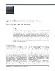
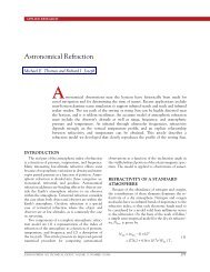
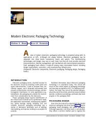
In this architecture, passive optical elements with low<br />
insertion loss are used to multiplex, filter, and demultiplex<br />
modulated optical carriers with negligible levels<br />
of crosstalk between the various signals. An example is<br />
shown in Fig. 6. Four lasers at different wavelengths are<br />
combined using a 4 1 multi plexer so that the output<br />
can be carried on a single optical fiber. At an intermediate<br />
point in the system, one wavelength is dropped<br />
from the stream using a narrowband optical filter. This<br />
wavelength is then modulated with an RF signal and<br />
added back to the stream using a second optical filter.<br />
The four-wavelength stream, with a single modulated<br />
wavelength, is then demultiplexed, with each wavelength<br />
going to a different photodetector. The crosstalk<br />
between the electrical outputs from each photodetector<br />
is generally better than –60 dB and can be better<br />
than –80 dB. These values are more than sufficient<br />
<strong>for</strong> successful electronic demultiplexing of the received<br />
signal. The passive optical filters described here are key<br />
elements in enabling a BCA system architecture that is<br />
robust and scalable.<br />
BCA SYSTEM DESIGN<br />
On the basis of the noise figure analysis described<br />
in the preceding section, as well as the other advantages<br />
of optical networks, a fiber-optic backbone is the<br />
proper design choice <strong>for</strong> higher-frequency (>300 MHz)<br />
BCA systems. Although the emphasis of this design is<br />
the reception of GPS signals,<br />
an additional goal is to provide<br />
a backbone that can scale to<br />
higher frequencies of interest.<br />
This backbone can consist of<br />
one fiber or multiple fibers. Consider<br />
the case where the BCA<br />
contains 12 individual antenna<br />
elements. These elements could<br />
be remoted by two fibers using<br />
314<br />
M<br />
U<br />
X<br />
Drop Add<br />
Modulator<br />
Detector<br />
Detector<br />
Detector<br />
Detector<br />
Figure 6. Wavelength division multiplexing using passive optical<br />
components. DEMUX, demultiplexer; MUX, multiplexer.<br />
D<br />
E<br />
M<br />
U<br />
X<br />
Shipboard<br />
12 optical carriers<br />
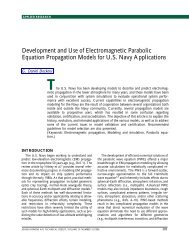
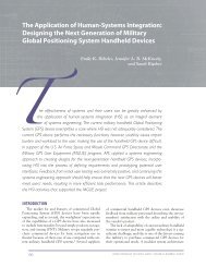
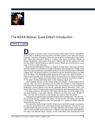
12 wavelengths, as shown in Fig. 7. One fiber would<br />
be used to transmit 12 unmodulated optical carriers,<br />
while 12 modulated optical carriers would return on the<br />
second fiber. However, the fiber plant itself would be a<br />
single point of failure in this architecture, since damage<br />
to the fiber or an optical filter could disable the entire<br />
system. Redundancy can be provided by using multiple<br />
fibers. Using 12 fiber pairs would provide full independence<br />
between antenna elements but would have a high<br />
degree of mechanical complexity. An intermediate<br />
number of fiber pairs, such as four, can be used to provide<br />
some redundancy without the challenges of a fully independent<br />
remoting architecture. This preferred option<br />
is illustrated in Fig. 8. Note that the use of 12 separate<br />
antenna elements also provides some degree of redundancy,<br />
because any one antenna is capable of receiving<br />
a GPS signal. Overall availability would be reduced if<br />
fewer than 12 antenna elements were accessible, but<br />
limited functionality would still be available. Additional<br />
details on the availability of individual elements and the<br />
<strong>over</strong>all system concept are given elsewhere. 7<br />
An additional constraint on the number of fibers is<br />
imposed by the requirement to use fiber-optic terminations<br />
between sections to support modular replacement<br />
and future expansion. Commercially available terminations<br />
that meet <strong>for</strong>m-factor requirements support a maximum<br />
of 12 fibers. Four wavelengths are used <strong>for</strong> each<br />
of the four fiber pairs, with the appropriate drop and<br />
add filters at each antenna element. These wavelengths<br />
are indicated by the colors red, orange, green, and blue<br />
in Fig. 8. The wavelengths are staggered so that each<br />
module is identical and could be replaced by a universal<br />
spare. Using three wavelengths <strong>for</strong> active remoting on<br />
each of the four fiber pairs leaves one wavelength per<br />
fiber pair unused. The additional wavelength can be<br />
used <strong>for</strong> future expansions by simply connecting an additional<br />
antenna module. This expansion capability can<br />
support additional GPS antenna modules or a different<br />
type of antenna module.<br />
For this antenna remoting architecture, multiple<br />
optical carriers are generated inboard using semiconductor<br />
lasers. The outputs of semiconductor lasers are<br />
horizontally polarized. The optical modulators used in<br />
the outboard portion of the BCA respond efficiently<br />
only when used with horizontally polarized light. Ordi-<br />
1 1 1 1 1 1 1 1 1 1<br />
1 2 3 4 12<br />
Figure 7. BCA with a single fiber pair. The fiber plant is a single point of failure.<br />
JOHNS HOPKINS APL TECHNICAL DIGEST, VOLUME 30, NUMBER 4 (2012)