The Wheatstone Bridge - Ryerson Department of Physics
The Wheatstone Bridge - Ryerson Department of Physics
The Wheatstone Bridge - Ryerson Department of Physics

You also want an ePaper? Increase the reach of your titles
YUMPU automatically turns print PDFs into web optimized ePapers that Google loves.
OBJECTIVE<br />
E9 - 1<br />
MEASUREMENT OF RESISTANCE USING A WHEATSTONE BRIDGE<br />
Various forms <strong>of</strong> the <strong>Wheatstone</strong> bridge are used to accurately determine the value <strong>of</strong> an<br />
unknown resistance, capacitance or inductance. In this experiment, a <strong>Wheatstone</strong> bridge will be<br />
used for the following purposes:<br />
1. To check the specified tolerance <strong>of</strong> five ± 5% carbon resistors<br />
2. To check the series and parallel formulas<br />
and<br />
THEORY<br />
R S = R 1 + R 2 + R 3 (a)<br />
for any three <strong>of</strong> the five resistors used for part 1.<br />
!<br />
1<br />
R P<br />
= 1<br />
+<br />
R1 1<br />
+<br />
R2 1<br />
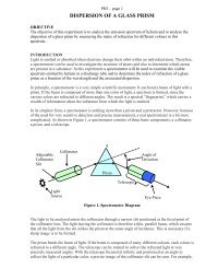
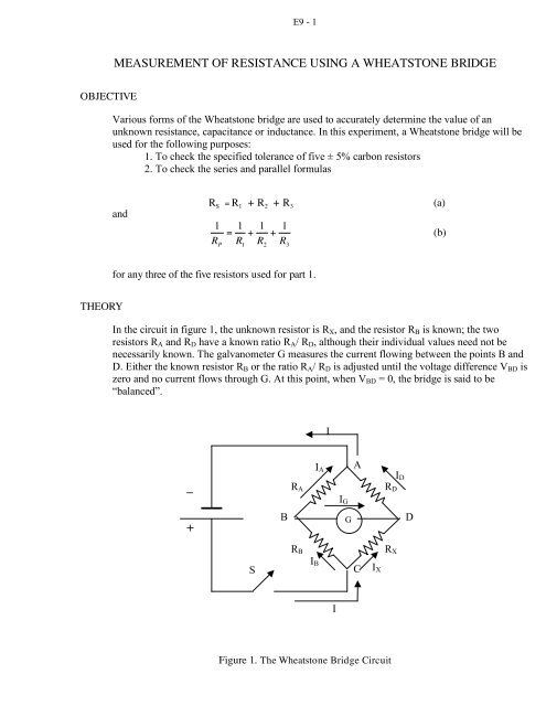
R3 In the circuit in figure 1, the unknown resistor is RX, and the resistor RB is known; the two<br />
resistors RA and RD have a known ratio RA/ RD, although their individual values need not be<br />
necessarily known. <strong>The</strong> galvanometer G measures the current flowing between the points B and<br />
D. Either the known resistor RB or the ratio RA/ RD is adjusted until the voltage difference VBD is<br />
zero and no current flows through G. At this point, when VBD = 0, the bridge is said to be<br />
“balanced”.<br />
_<br />
+<br />
S<br />
B<br />
RA<br />
RB<br />
Figure 1. <strong>The</strong> <strong>Wheatstone</strong> <strong>Bridge</strong> Circuit<br />
IB<br />
IA<br />
I<br />
I<br />
IG<br />
G<br />
A<br />
C<br />
IX<br />
RD<br />
RX<br />
ID<br />
D<br />
(b)
E9 - 2<br />
<strong>The</strong>refore, the following relationships will hold true for the electric potentials VA, VB, VC and<br />
VD and the voltages (potential differences) VCB, VCD, VBA and VDA in the four branches.<br />
First, for the branches marked CB and CD:<br />
V CB = V C – V B = I B R B (1)<br />
V CD = V C – V D = I X R X (2)<br />
And since the bridge is balanced:<br />
V BD = V B – V D = 0 (3)<br />
From (1), (2) and (3) we obtain:<br />
V BD = V B – V D = (I B R B - V C) - (I X R x - V C) = 0 (4)<br />
<strong>The</strong>refore:<br />
I B R B = I X R x (5)<br />
Since the current through the galvanometer IG = 0, according toKirchh<strong>of</strong>f’s first law for the<br />
junctions denoted B and D, we have:<br />
I A = I B (6)<br />
I D = I X (7)<br />
Similar to equations (1) to (3), for the branches marked BA and DA, we have:<br />
VBA = V B – V A = I A R A (8)<br />
V DA = V D – V A = I D R D (9)<br />
And since the bridge is balanced:<br />
V BD = V B – V D = 0 (10)<br />
Now, from equations (8), (9) and (10):<br />
Or:<br />
and using (6) and (7), we obtain<br />
V BD = V B – V D = (I A R A + V A) - (I D R D + V A) = 0 (11)<br />
I A R A = I D R D (12)<br />
I B R A = I X R D (13)<br />
Dividing equations (13) by equation (5) we get: I B R B = I X R x<br />
and solving for R X :<br />
!<br />
!<br />
RX RD = R B<br />
R A<br />
R X = R B " R D<br />
R A<br />
(14)<br />
(15)
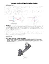
PROCEDURE<br />
E9 - 3<br />
Set up the <strong>Wheatstone</strong> bridge circuit as in Figure 2.<br />
Figure 2: Actual setup <strong>of</strong> the <strong>Wheatstone</strong> bridge.<br />
Use the precision 500 Ω for R A and the decade resistance box for R B • R C is a variable resistor,<br />
continuously adjustable from 0 to 1 kΩ. R X is the resistor whose resistance is to be measured. <strong>The</strong><br />
galvanometer G is a sensitive current sensing meter.<br />
Precaution:<br />
If the galvanometer swings rapidly <strong>of</strong>f scale when the switch S is closed, then release the<br />
switch quickly. Check and/or adjust your circuit before closing the switch again.<br />
To determine the value <strong>of</strong> R X:<br />
a. set the resistance box at about double the expected nominal value <strong>of</strong> the resistor R X<br />
(use the colour code on page 5).<br />
b. Close the switch S and adjust R D until the galvanometer reads zero. <strong>The</strong> bridge is<br />
now balanced.<br />
DATA ANALYSIS<br />
Part A: Use the table below to record your data, and apply the method described in the theory<br />
section above to measure the resistance <strong>of</strong> six resistors <strong>of</strong> different values. Determine the<br />
percentage difference between the calculated and expected resistance values (use the colour coding<br />
table at the end <strong>of</strong> this set <strong>of</strong> instructions to determine the manufacturer predicted resistance).<br />
R B<br />
(kΩ)<br />
_<br />
+<br />
R D<br />
(kΩ)<br />
S<br />
R A<br />
(kΩ)<br />
0.5<br />
0.5<br />
!<br />
0.5<br />
0.5<br />
0.5<br />
0.5<br />
B<br />
RA<br />
RB<br />
- decade box<br />
G<br />
A<br />
C<br />
R X1 = R B " R D<br />
R A<br />
(kΩ)<br />
RD = Rpot<br />
0 → 1 kΩ<br />
D<br />
R1, R2, R3, . . . R6<br />
Expected Value<br />
(Colour Code)<br />
(kΩ)<br />
Percentage<br />
Difference (%)
E9 - 4<br />
Part B: Use the table below to record your data, and apply the method described in the theory<br />
section above to measure the resistance <strong>of</strong> any three <strong>of</strong> the previous six resistors connected in<br />
series. Determine the percentage difference between the calculated and expected value.<br />
R B<br />
(kΩ)<br />
R B<br />
(kΩ)<br />
R D<br />
(kΩ)<br />
R A<br />
(kΩ)<br />
!<br />
R S = R B " R D<br />
R A<br />
(kΩ)<br />
Expected:<br />
R S= R 1 + R 2+ R 3<br />
(kΩ)<br />
Percentage<br />
Difference (%)<br />
Part C: Use the table below to record your data, and apply the method described in the theory<br />
section above to measure the resistance <strong>of</strong> the same three resistors used in part B, connected in<br />
parallel this time. Determine the percentage difference between the calculated and expected value.<br />
CONCLUSIONS<br />
R D<br />
(kΩ)<br />
R A<br />
(kΩ)<br />
!<br />
R P = R B " R D<br />
R A<br />
(kΩ)<br />
(1) Are all six resistors within the expected tolerance?<br />
(2) Do the series and parallel equivalent resistance formulas:<br />
!<br />
Expected:<br />
RP = 1<br />
+<br />
R1 1<br />
+<br />
R2 1<br />
"<br />
%<br />
$<br />
'<br />
# R3 &<br />
(kΩ)<br />
RS = R1 + R2 + R3 (a)<br />
1<br />
RP = 1<br />
+<br />
R1 1<br />
R2 + 1<br />
R3 (b)<br />
hold true within experimental error?<br />
(1<br />
Percentage<br />
Difference (%)<br />
(3) In ! case the expected and measured values are a lot more different, explain the possible<br />
causes for this difference.<br />
(4) How reliable does the <strong>Wheatstone</strong> bridge method seem to be in determining precisely<br />
the resistance <strong>of</strong> an electric circuit?
COLOUR CODES FOR RESISTORS.<br />
E9 - 5<br />
Resistors are usually marked with coloured bands or rings to allow for identification. Referred to as<br />
colour codes, these markings are indicative <strong>of</strong> their resistance, and tolerance.<br />
A: first significant figure<br />
B: second significant figure<br />
C: third significant figure (in case <strong>of</strong> only 4 coloured bands, the third significant digit is not given!)<br />
D: multiplier (factor by which the significant figures are multiplied to yield the nominal value)<br />
E: tolerance (%)<br />
Examples:<br />
Colour Colour<br />
Name<br />
Digit<br />
"A"<br />
Digit<br />
"B"<br />
Digit<br />
"C"<br />
Black 0 0 0 1<br />
Multiplier<br />
"D"<br />
Brown 1 1 1 10 ±1%<br />
Red 2 2 2 100 ±2%<br />
Orange 3 3 3 1k<br />
Yellow 4 4 4 10k<br />
Tolerance<br />
"E"<br />
Green 5 5 5 100k ±0.5%<br />
Blue 6 6 6 1M ±0.25%<br />
Violet 7 7 7 10M ±0.1%<br />
Gray 8 8 8<br />
White 9 9 9<br />
Gold 0.1 ±5%<br />
Silver 0.01 ±10%<br />
Colour Code Resistance<br />
A=Brown, B=Red, D=Orange, E=Gold. 12 KOhm ±5%<br />
A=Brown, B=Red, D=Orange, E=Gold. 12 KOhm ±5%<br />
A=Red, B=Violet, D=Green, E=Yellow 2.7 MOhm ±5%<br />
A=Gray, B=Red, D=Orange, E=Gold. 82 KOhm ±5%<br />
A=Yellow, B=Violet, C=Black, D=Red, E=Brown. 47 KOhm ±1%<br />
A=Orange, B=White, C=Black, D=Orange, E=Brown 390 KOhm ±1%