

Rosemount 5300 Series Superior Performance Guided Wave Radar ...
Rosemount 5300 Series Superior Performance Guided Wave Radar ...
Rosemount 5300 Series Superior Performance Guided Wave Radar ...

You also want an ePaper? Increase the reach of your titles
YUMPU automatically turns print PDFs into web optimized ePapers that Google loves.
Quick Installation Guide<br />
Step 3 continued...<br />
12<br />
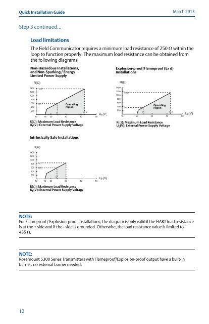
Load limitations<br />
March 2013<br />
The Field Communicator requires a minimum load resistance of 250 within the<br />
loop to function properly. The maximum load resistance can be obtained from<br />
the following diagrams.<br />
Non-Hazardous Installations,<br />
and Non-Sparking / Energy<br />
Limited Power Supply<br />
Operating<br />
region<br />
R(): Maximum Load Resistance<br />
U E (V): External Power Supply Voltage<br />
Intrinsically Safe Installations<br />
R(): Maximum Load Resistance<br />
U E (V): External Power Supply Voltage<br />
Explosion-proof/Flameproof (Ex d)<br />
Installations<br />
Operating<br />
region<br />
R(): Maximum Load Resistance<br />
U E (V): External Power Supply Voltage<br />
NOTE:<br />
For Flameproof / Explosion-proof installations, the diagram is only valid if the HART load resistance<br />
is at the + side and if the - side is grounded. Otherwise, the load resistance value is limited to<br />
435 .<br />
NOTE:<br />
<strong>Rosemount</strong> <strong>5300</strong> <strong>Series</strong> Transmitters with Flameproof/Explosion-proof output have a built-in<br />
barrier; no external barrier needed.


