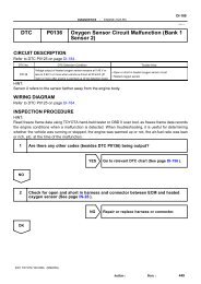
DTC P0325 Knock Sensor 1 Circuit Malfunction (Bank 1) DTC ...
DTC P0325 Knock Sensor 1 Circuit Malfunction (Bank 1) DTC ...
DTC P0325 Knock Sensor 1 Circuit Malfunction (Bank 1) DTC ...

Create successful ePaper yourself
Turn your PDF publications into a flip-book with our unique Google optimized e-Paper software.
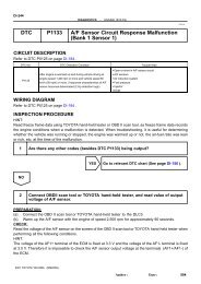
<strong>Knock</strong> <strong>Sensor</strong> 27<br />
1 1 1<br />
1<br />
2<br />
Female<br />
Connector<br />
2<br />
Male<br />
Connector<br />
ED1<br />
ECM<br />
KNK1<br />
KNK2<br />
FI7050<br />
A00053<br />
A00054 A09708<br />
0.5 V<br />
/Division<br />
FI6510<br />
FI6607<br />
0V<br />
200 mV<br />
/Division<br />
0V<br />
EB<br />
E8<br />
28<br />
E8<br />
KNK Signal Waveform<br />
5 msec./Division<br />
0.1 msec./Division<br />
2001 TOYOTA TACOMA (RM835U)<br />
DIAGNOSTICS - ENGINE (5VZ-FE)<br />
A00113<br />
Author: Date:<br />
DI-205<br />
Read freeze frame data using TOYOTA hand-held tester or OBD II scan tool, as freeze frame data<br />
records the engine conditions when a malfunction is detected. When troubleshooting, it is useful for<br />
determining whether the vehicle was running or stopped, the engine was warmed up or not, the air-fuel<br />
ratio was lean or rich, etc. at the time of the malfunction.<br />
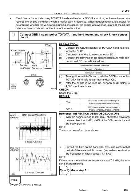
1 Connect OBD II scan tool or TOYOTA hand-held tester, and check knock sensor<br />
circuit.<br />
Type I<br />
PREPARATION:<br />
(a) Connect the OBD II scan tool or TOYOTA hand-held tester<br />
to the DLC3.<br />
(b) Disconnect the wire to wire connector ED1.<br />
(c) Connect the terminals of the disconnected ED1 male connector<br />
and ED1 female as follows.<br />
Male connector - Female connector<br />
Terminal 1 - Terminal 2<br />
Terminal 2 - Terminal 1<br />
(d) Turn ignition switch ON and push the OBDII scan tool or<br />
TOYOTA hand-held tester main switch ON.<br />
(e) After the engine is warmed up, perform quick racing to<br />
4,000 rpm three times.<br />
CHECK:<br />
Check the <strong>DTC</strong>.<br />
RESULT:<br />
Type I<br />
Type II<br />
<strong>DTC</strong> same as when vehicle brought in<br />
<strong>P0325</strong> → <strong>P0325</strong> or P0330 → P0330<br />
<strong>DTC</strong> different to when vehicle brought in<br />
<strong>P0325</strong> → P0330 or P0330 → <strong>P0325</strong><br />
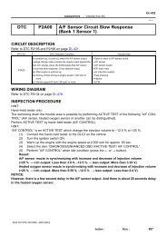
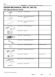
Reference: INSPECTION USING OSCILLOSCOPE<br />
With the engine racing (4,000 rpm), check the waveform<br />
between terminal KNK1, KNK2 of the ECM connector and<br />
the body ground.<br />
HINT:<br />
The correct waveform is as shown.<br />
Spread the time on the horizontal axis, and confirm that<br />
period of the wave is 0.141 msec. (Normal mode vibration<br />
the frequency of knock sensor: 7.1 kHz)<br />
HINT:<br />
If the normal mode vibration frequency is not 7.1 kHz, the sensor<br />
is malfunctioning.<br />
Type II Go to step 3.<br />
465
![F RELAY LOCATIONS [Engine Compartment] [Instrument Panel] 20](https://img.yumpu.com/53634281/1/184x260/f-relay-locations-engine-compartment-instrument-panel-20.jpg?quality=85)