DTC P2A00 A/F Sensor Circuit Slow Response (Bank 1 Sensor 1)
DTC P2A00 A/F Sensor Circuit Slow Response (Bank 1 Sensor 1)
DTC P2A00 A/F Sensor Circuit Slow Response (Bank 1 Sensor 1)
- No tags were found...

Create successful ePaper yourself
Turn your PDF publications into a flip-book with our unique Google optimized e-Paper software.
DIAGNOSTICS<br />
–<br />
ENGINE (5VZ–FE)<br />
DI–435<br />
DIB2A–01<br />
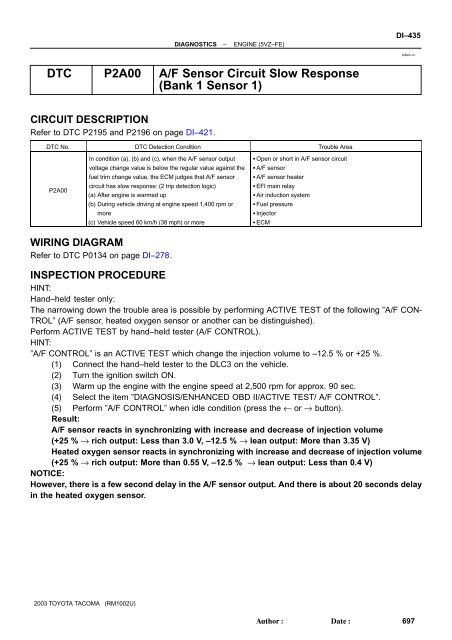
<strong>DTC</strong> <strong>P2A00</strong> A/F <strong>Sensor</strong> <strong>Circuit</strong> <strong>Slow</strong> <strong>Response</strong><br />
(<strong>Bank</strong> 1 <strong>Sensor</strong> 1)<br />
CIRCUIT DESCRIPTION<br />
Refer to <strong>DTC</strong> P2195 and P2196 on page DI–421.<br />
<strong>DTC</strong> No. <strong>DTC</strong> Detection Condition Trouble Area<br />
<strong>P2A00</strong><br />
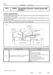
In condition (a), (b) and (c), when the A/F sensor output<br />
voltage change value is below the regular value against the<br />
fuel trim change value, the ECM judges that A/F sensor<br />
circuit has slow response: (2 trip detection logic)<br />
(a) After engine is warmed up<br />
(b) During vehicle driving at engine speed 1,400 rpm or<br />
more<br />
(c) Vehicle speed 60 km/h (38 mph) or more<br />
Open or short in A/F sensor circuit<br />
A/F sensor<br />
A/F sensor heater<br />
EFI main relay<br />
Air induction system<br />
Fuel pressure<br />
Injector<br />
ECM<br />
WIRING DIAGRAM<br />
Refer to <strong>DTC</strong> P0134 on page DI–278.<br />
INSPECTION PROCEDURE<br />
HINT:<br />
Hand–held tester only:<br />
The narrowing down the trouble area is possible by performing ACTIVE TEST of the following ”A/F CON-<br />
TROL” (A/F sensor, heated oxygen sensor or another can be distinguished).<br />
Perform ACTIVE TEST by hand–held tester (A/F CONTROL).<br />
HINT:<br />
”A/F CONTROL” is an ACTIVE TEST which change the injection volume to –12.5 % or +25 %.<br />
(1) Connect the hand–held tester to the DLC3 on the vehicle.<br />
(2) Turn the ignition switch ON.<br />
(3) Warm up the engine with the engine speed at 2,500 rpm for approx. 90 sec.<br />
(4) Select the item ”DIAGNOSIS/ENHANCED OBD II/ACTIVE TEST/ A/F CONTROL”.<br />
(5) Perform ”A/F CONTROL” when idle condition (press the ← or → button).<br />
Result:<br />
A/F sensor reacts in synchronizing with increase and decrease of injection volume<br />
(+25 % → rich output: Less than 3.0 V, –12.5 % → lean output: More than 3.35 V)<br />
Heated oxygen sensor reacts in synchronizing with increase and decrease of injection volume<br />
(+25 % → rich output: More than 0.55 V, –12.5 % → lean output: Less than 0.4 V)<br />
NOTICE:<br />
However, there is a few second delay in the A/F sensor output. And there is about 20 seconds delay<br />
in the heated oxygen sensor.<br />
2003 TOYOTA TACOMA (RM1002U)<br />
Author:<br />
Date:<br />
697
DI–436<br />
DIAGNOSTICS<br />
–<br />
ENGINE (5VZ–FE)<br />
Output voltage of A/F sensor<br />
(sensor 1)<br />
Output voltage of heated oxygen<br />
sensor (sensor 2)<br />
Mainly suspect trouble<br />
area<br />
Case 1<br />
Injection volume<br />
+25 %<br />
–12.5 %<br />
Output voltage<br />
More than 3.35 V<br />
Less than 3.0 V<br />
OK<br />
Injection volume<br />
+25 %<br />
–12.5 %<br />
Output voltage<br />
More than 0.55 V<br />
Less than 0.4 V<br />
OK<br />
<br />
Case 2<br />
Injection volume<br />
+25 %<br />
–12.5 %<br />
Output voltage<br />
No reaction<br />
NG<br />
Injection volume<br />
+25 %<br />
–12.5 %<br />
Output voltage<br />
More than 0.55 V<br />
Less than 0.4 V<br />
OK<br />
A/F sensor<br />
(A/F sensor, heater,<br />
A/F sensor circuit)<br />
Case 3<br />
Injection volume<br />
+25 %<br />
–12.5 %<br />
Output voltage<br />
More than 3.35 V<br />
Less than 3.0 V<br />
OK<br />
Injection volume<br />
+25 %<br />
–12.5 %<br />
Output voltage<br />
No reaction<br />
NG<br />
Heated oxygen sensor<br />
(heated oxygen sensor,<br />
heater, heated oxygen<br />
sensor circuit)<br />
Case 4<br />
Injection volume<br />
+25 %<br />
–12.5 %<br />
Output voltage<br />
No reaction<br />
NG<br />
Injection volume<br />
+25 %<br />
–12.5 %<br />
Output voltage<br />
No reaction<br />
NG<br />
Extremely rich or lean of<br />
the actual air–fuel ratio<br />
(Injector, fuel pressure,<br />
gas leakage in exhaust<br />
system, etc)<br />
The following procedure of A/F CONTROL enable that to check its output (show its graph indication) of A/F<br />
sensor and heated oxygen sensor.<br />
To display the graph indication. Select and push the ”YES or NO” button 2 data ”AFS B1S1 and O2S B1S2”<br />
or ”AFS B2S1 and O2S B2S2” and press button ”4” after selecting ”ACTIVE TEST/ A/F CONTROL/USER<br />
DATA”.<br />
HINT:<br />
The A/F sensor signal must be checked using the hand–held tester or the OBD II scan tool.<br />
<strong>DTC</strong> <strong>P2A00</strong> may be also detected, when the air fuel ratio is stuck rich or lean.<br />
A low A/F sensor voltage could be caused by a rich air fuel mixture. Check for conditions that would<br />
cause the engine to run rich.<br />
A high A/F sensor voltage could be caused by a lean air fuel mixture. Check for conditions that would<br />
cause the engine to run lean.<br />
Read freeze frame data using the hand–held tester or the OBD II scan tool, as freeze frame records<br />
the engine conditions when a malfunction is detected. When troubleshooting, it is useful for determining<br />
whether the vehicle was running or stopped, the engine was warmed up or not, the air–fuel ratio<br />
was lean or rich, etc. at the time of the malfunction.<br />
2003 TOYOTA TACOMA (RM1002U)<br />
Author:<br />
Date:<br />
698
DIAGNOSTICS<br />
–<br />
ENGINE (5VZ–FE)<br />
DI–437<br />
1 Are there any other codes (besides <strong>DTC</strong> <strong>P2A00</strong>) being output?<br />
YES<br />
Go to relevant <strong>DTC</strong> chart (See page DI–231).<br />
NO<br />
2 Connect OBDII scan tool or hand–held tester, and read value for voltage output<br />
of A/F sensor.<br />
PREPARATION:<br />
(a) Connect the hand–held tester or the OBD II scan tool to the DLC 3.<br />
(b) Warm up the A/F sensor (bank 1 sensor 1) with the engine at 2,500 rpm for approximately 90 seconds.<br />
(c) Read A/F sensor voltage on the OBD II scan tool or hand–held tester.<br />
CHECK:<br />
(a) Hand–held tester only:<br />
Select the ”DIAGNOSIS/ENHANCED OBD II/SNAPSHOT/MANUAL SNAPSHOT/USER DATA” mode<br />
on the hand–held tester.<br />
(b) Select ”AFS B1 S1/ENGINE SPD” and press button ”YES”.<br />
(c) Monitor the A/F sensor voltage carefully.<br />
(d) Check the A/F sensor voltage under the condition as follows.<br />
(1) Allow engine to idle for 30 seconds.<br />
(2) Engine is racing at approx. 2,500 rpm (when engine revolution is not suddenly changed).<br />
(3) Raise the engine speed to 4,000 rpm and release the accelerator pedal fully closed quickly.<br />
OK:<br />
Standard:<br />
Condition (1) and (2)<br />
Voltage change a little in the vicinity of 3.3 V (0.66 V)* (between approx. 3.1 – 3.5 V) as shown in the<br />
illustration.<br />
Condition (3)<br />
A/F ratio sensor voltage increase to 3.8 V (0.76 V)* or more during engine deceleration (when fuel cut)<br />
as shown in the illustration.<br />
2003 TOYOTA TACOMA (RM1002U)<br />
Author:<br />
Date:<br />
699
DI–438<br />
DIAGNOSTICS<br />
–<br />
ENGINE (5VZ–FE)<br />
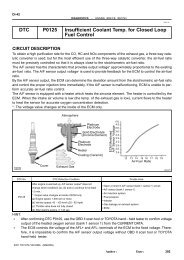
Normal Condition<br />
Malfunction Condition<br />
(3) Approx. 4,000 rpm<br />
(2) Approx. 2,500 rpm<br />
(3) Approx. 4,000 rpm<br />
(2) Approx. 2,500 rpm<br />
Engine<br />
Revolution<br />
A/F Ratio<br />
<strong>Sensor</strong><br />
Voltage<br />
(1) Idle<br />
”Condition (3)”<br />
3.8 V or More<br />
”Condition (1), (2)”<br />
Change a little in vicinity of<br />
Approx. 3.3 V<br />
Fuel Cut<br />
(1) Idle<br />
Engine<br />
Revolution<br />
A/F Ratio<br />
<strong>Sensor</strong><br />
Voltage<br />
(1) Idle<br />
Fuel Cut<br />
(1) Idle<br />
”Condition (1), (2), (3)”<br />
When A/F Ratio <strong>Sensor</strong> <strong>Circuit</strong> is Malfunctioning,<br />
Voltage Value Does Not Change at All<br />
A20014<br />
HINT:<br />
Whenever the output voltage of the A/F sensor remains at approx. 3.3 V (0.660 V)* (see dwg. 2) under<br />
any conditions as well as the above conditions, the A/F sensor may have an open–circuit. (This will<br />
happen also when the A/F sensor heater has an open–circuit.)<br />
Whenever the output voltage of the A/F sensor remains at a certain value of approx. 3.8 V (0.76 V)*<br />
or more, or 2.8 V (0.56 V)* or less (see dwg. 2) under any conditions as well as the above conditions,<br />
the A/F sensor may have a short–circuit.<br />
The ECM will stop fuel injection (fuel cut) during engine deceleration. This will cause a lean condition<br />
and should result in a momentary increase in A/F ratio sensor voltage.<br />
The ECM must establish a closed throttle position learned value to perform fuel cut. If the battery terminal<br />
has been disconnected, the vehicle must be driven over 10 mph to allow the ECM to relearn the<br />
closed throttle position.<br />
When the vehicle is driven:<br />
In the case that the output voltage of the A/F sensor is below 2.8 V (0.76 V)* during fuel enrichment<br />
(for example, when the vehicle tries to overtake another vehicle on a highway, the vehicle speed is<br />
suddenly increased with the accelerator pedal fully depressed), the A/F sensor are functioning normally.<br />
The A/F sensor is a current output element, and therefore the current is converted into voltage inside<br />
the ECM. If measuring voltage at connectors of A/F ratio sensor or ECM, you can obtain a constant<br />
voltage.<br />
*: When using the OBD II scan tool (excluding hand–held tester).<br />
OK Go to step 13.<br />
NG<br />
2003 TOYOTA TACOMA (RM1002U)<br />
Author:<br />
Date:<br />
700
DIAGNOSTICS<br />
–<br />
ENGINE (5VZ–FE)<br />
DI–439<br />
3 Check resistance of A/F sensor heater.<br />
Ohmmeter<br />
+B<br />
HT<br />
PREPARATION:<br />
Disconnect the sensor connector.<br />
CHECK:<br />
Using an ohmmeter, measure the resistance between terminals<br />
+B and HT.<br />
OK:<br />
B08732<br />
at 20°C (68°F)<br />
at 800°C (1,472°F)<br />
0.8 – 1.4 Ω<br />
1.8 – 3.2 Ω<br />
NG<br />
Replace A/F sensor.<br />
OK<br />
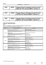
4 Check EFI main relay (Marking : EFI).<br />
2 5 3<br />
3<br />
5<br />
1 2<br />
PREPARATION:<br />
Remove the EFI main relay from RB No. 2.<br />
CHECK:<br />
Inspect the EFI main relay.<br />
OK:<br />
Condition Tester connection Specified condition<br />
1<br />
Constant<br />
t<br />
1 – 2 Continuity<br />
3 – 5 No continuity<br />
I05027<br />
Apply B+ between<br />
terminals 1 and 2.<br />
3 – 5 Continuity<br />
NG<br />
Replace EFI main relay<br />
OK<br />
5 Check for open and short in harness and connector between ECM and A/F sensor<br />
(See page IN–28).<br />
NG<br />
Repair or replace harness or connector.<br />
OK<br />
2003 TOYOTA TACOMA (RM1002U)<br />
Author:<br />
Date:<br />
701
DI–440<br />
DIAGNOSTICS<br />
–<br />
ENGINE (5VZ–FE)<br />
6 Check air induction system (See page SF–1).<br />
NG<br />
Repair or replace.<br />
OK<br />
7 Check fuel pressure (See page SF–5).<br />
NG<br />
Check and repair fuel pump, pressure regulator,<br />
fuel pipe line and filter (See page SF–1).<br />
OK<br />
8 Check injector injection (See page SF–19).<br />
NG<br />
Replace injector.<br />
OK<br />
9 Replace A/F sensor.<br />
GO<br />
10 Perform confirmation driving pattern (See page DI–421).<br />
GO<br />
2003 TOYOTA TACOMA (RM1002U)<br />
Author:<br />
Date:<br />
702
DIAGNOSTICS<br />
–<br />
ENGINE (5VZ–FE)<br />
DI–441<br />
11 Is there <strong>DTC</strong> <strong>P2A00</strong> being output again?<br />
YES<br />
Check and replace ECM (See page IN–28) and<br />
perform confirmation driving pattern (See page<br />
DI–421).<br />
NO<br />
12 Did vehicle run out of fuel in past?<br />
NO<br />
Check for intermittent problems<br />
(See page DI–218).<br />
YES<br />
<strong>DTC</strong> <strong>P2A00</strong> is caused by shortage of fuel.<br />
13 Perform confirmation driving pattern (See page DI–421).<br />
Go<br />
14 Is there <strong>DTC</strong> <strong>P2A00</strong> being output again?<br />
NO Go to step 18.<br />
YES<br />
15 Replace A/F sensor.<br />
GO<br />
2003 TOYOTA TACOMA (RM1002U)<br />
Author:<br />
Date:<br />
703
DI–442<br />
DIAGNOSTICS<br />
–<br />
ENGINE (5VZ–FE)<br />
16 Perform confirmation driving pattern (See page DI–421).<br />
GO<br />
17 Is there <strong>DTC</strong> <strong>P2A00</strong> being output again?<br />
YES<br />
Check and replace ECM (See page IN–28) and<br />
perform confirmation driving pattern (See page<br />
DI–421).<br />
NO<br />
18 Did vehicle run out of fuel in past?<br />
NO<br />
Check for intermittent problems<br />
(See page DI–218).<br />
YES<br />
<strong>DTC</strong> <strong>P2A00</strong> is caused by shortage of fuel.<br />
2003 TOYOTA TACOMA (RM1002U)<br />
Author:<br />
Date:<br />
704
![F RELAY LOCATIONS [Engine Compartment] [Instrument Panel] 20](https://img.yumpu.com/53634281/1/184x260/f-relay-locations-engine-compartment-instrument-panel-20.jpg?quality=85)