DTC P2A00 A/F Sensor Circuit Slow Response (Bank 1 Sensor 1)
DTC P2A00 A/F Sensor Circuit Slow Response (Bank 1 Sensor 1)
DTC P2A00 A/F Sensor Circuit Slow Response (Bank 1 Sensor 1)
- No tags were found...

You also want an ePaper? Increase the reach of your titles
YUMPU automatically turns print PDFs into web optimized ePapers that Google loves.
DI–436<br />
DIAGNOSTICS<br />
–<br />
ENGINE (5VZ–FE)<br />
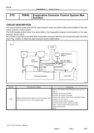
Output voltage of A/F sensor<br />
(sensor 1)<br />
Output voltage of heated oxygen<br />
sensor (sensor 2)<br />
Mainly suspect trouble<br />
area<br />
Case 1<br />
Injection volume<br />
+25 %<br />
–12.5 %<br />
Output voltage<br />
More than 3.35 V<br />
Less than 3.0 V<br />
OK<br />
Injection volume<br />
+25 %<br />
–12.5 %<br />
Output voltage<br />
More than 0.55 V<br />
Less than 0.4 V<br />
OK<br />
<br />
Case 2<br />
Injection volume<br />
+25 %<br />
–12.5 %<br />
Output voltage<br />
No reaction<br />
NG<br />
Injection volume<br />
+25 %<br />
–12.5 %<br />
Output voltage<br />
More than 0.55 V<br />
Less than 0.4 V<br />
OK<br />
A/F sensor<br />
(A/F sensor, heater,<br />
A/F sensor circuit)<br />
Case 3<br />
Injection volume<br />
+25 %<br />
–12.5 %<br />
Output voltage<br />
More than 3.35 V<br />
Less than 3.0 V<br />
OK<br />
Injection volume<br />
+25 %<br />
–12.5 %<br />
Output voltage<br />
No reaction<br />
NG<br />
Heated oxygen sensor<br />
(heated oxygen sensor,<br />
heater, heated oxygen<br />
sensor circuit)<br />
Case 4<br />
Injection volume<br />
+25 %<br />
–12.5 %<br />
Output voltage<br />
No reaction<br />
NG<br />
Injection volume<br />
+25 %<br />
–12.5 %<br />
Output voltage<br />
No reaction<br />
NG<br />
Extremely rich or lean of<br />
the actual air–fuel ratio<br />
(Injector, fuel pressure,<br />
gas leakage in exhaust<br />
system, etc)<br />
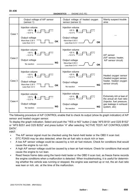
The following procedure of A/F CONTROL enable that to check its output (show its graph indication) of A/F<br />
sensor and heated oxygen sensor.<br />
To display the graph indication. Select and push the ”YES or NO” button 2 data ”AFS B1S1 and O2S B1S2”<br />
or ”AFS B2S1 and O2S B2S2” and press button ”4” after selecting ”ACTIVE TEST/ A/F CONTROL/USER<br />
DATA”.<br />
HINT:<br />
The A/F sensor signal must be checked using the hand–held tester or the OBD II scan tool.<br />
<strong>DTC</strong> <strong>P2A00</strong> may be also detected, when the air fuel ratio is stuck rich or lean.<br />
A low A/F sensor voltage could be caused by a rich air fuel mixture. Check for conditions that would<br />
cause the engine to run rich.<br />
A high A/F sensor voltage could be caused by a lean air fuel mixture. Check for conditions that would<br />
cause the engine to run lean.<br />
Read freeze frame data using the hand–held tester or the OBD II scan tool, as freeze frame records<br />
the engine conditions when a malfunction is detected. When troubleshooting, it is useful for determining<br />
whether the vehicle was running or stopped, the engine was warmed up or not, the air–fuel ratio<br />
was lean or rich, etc. at the time of the malfunction.<br />
2003 TOYOTA TACOMA (RM1002U)<br />
Author:<br />
Date:<br />
698
![F RELAY LOCATIONS [Engine Compartment] [Instrument Panel] 20](https://img.yumpu.com/53634281/1/184x260/f-relay-locations-engine-compartment-instrument-panel-20.jpg?quality=85)