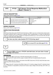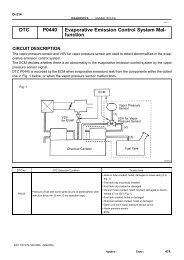
DTC P2A00 A/F Sensor Circuit Slow Response (Bank 1 Sensor 1)
DTC P2A00 A/F Sensor Circuit Slow Response (Bank 1 Sensor 1)
DTC P2A00 A/F Sensor Circuit Slow Response (Bank 1 Sensor 1)
- No tags were found...

Create successful ePaper yourself
Turn your PDF publications into a flip-book with our unique Google optimized e-Paper software.
DIAGNOSTICS<br />
–<br />
ENGINE (5VZ–FE)<br />
DI–437<br />
1 Are there any other codes (besides <strong>DTC</strong> <strong>P2A00</strong>) being output?<br />
YES<br />
Go to relevant <strong>DTC</strong> chart (See page DI–231).<br />
NO<br />
2 Connect OBDII scan tool or hand–held tester, and read value for voltage output<br />
of A/F sensor.<br />
PREPARATION:<br />
(a) Connect the hand–held tester or the OBD II scan tool to the DLC 3.<br />
(b) Warm up the A/F sensor (bank 1 sensor 1) with the engine at 2,500 rpm for approximately 90 seconds.<br />
(c) Read A/F sensor voltage on the OBD II scan tool or hand–held tester.<br />
CHECK:<br />
(a) Hand–held tester only:<br />
Select the ”DIAGNOSIS/ENHANCED OBD II/SNAPSHOT/MANUAL SNAPSHOT/USER DATA” mode<br />
on the hand–held tester.<br />
(b) Select ”AFS B1 S1/ENGINE SPD” and press button ”YES”.<br />
(c) Monitor the A/F sensor voltage carefully.<br />
(d) Check the A/F sensor voltage under the condition as follows.<br />
(1) Allow engine to idle for 30 seconds.<br />
(2) Engine is racing at approx. 2,500 rpm (when engine revolution is not suddenly changed).<br />
(3) Raise the engine speed to 4,000 rpm and release the accelerator pedal fully closed quickly.<br />
OK:<br />
Standard:<br />
Condition (1) and (2)<br />
Voltage change a little in the vicinity of 3.3 V (0.66 V)* (between approx. 3.1 – 3.5 V) as shown in the<br />
illustration.<br />
Condition (3)<br />
A/F ratio sensor voltage increase to 3.8 V (0.76 V)* or more during engine deceleration (when fuel cut)<br />
as shown in the illustration.<br />
2003 TOYOTA TACOMA (RM1002U)<br />
Author:<br />
Date:<br />
699
![F RELAY LOCATIONS [Engine Compartment] [Instrument Panel] 20](https://img.yumpu.com/53634281/1/184x260/f-relay-locations-engine-compartment-instrument-panel-20.jpg?quality=85)