DTC P2A00 A/F Sensor Circuit Slow Response (Bank 1 Sensor 1)
DTC P2A00 A/F Sensor Circuit Slow Response (Bank 1 Sensor 1)
DTC P2A00 A/F Sensor Circuit Slow Response (Bank 1 Sensor 1)
- No tags were found...

Create successful ePaper yourself
Turn your PDF publications into a flip-book with our unique Google optimized e-Paper software.
DIAGNOSTICS<br />
–<br />
ENGINE (5VZ–FE)<br />
DI–439<br />
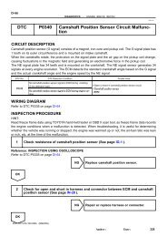
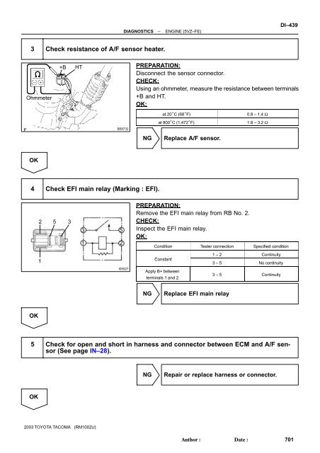
3 Check resistance of A/F sensor heater.<br />
Ohmmeter<br />
+B<br />
HT<br />
PREPARATION:<br />
Disconnect the sensor connector.<br />
CHECK:<br />
Using an ohmmeter, measure the resistance between terminals<br />
+B and HT.<br />
OK:<br />
B08732<br />
at 20°C (68°F)<br />
at 800°C (1,472°F)<br />
0.8 – 1.4 Ω<br />
1.8 – 3.2 Ω<br />
NG<br />
Replace A/F sensor.<br />
OK<br />
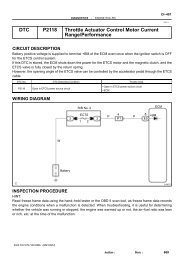
4 Check EFI main relay (Marking : EFI).<br />
2 5 3<br />
3<br />
5<br />
1 2<br />
PREPARATION:<br />
Remove the EFI main relay from RB No. 2.<br />
CHECK:<br />
Inspect the EFI main relay.<br />
OK:<br />
Condition Tester connection Specified condition<br />
1<br />
Constant<br />
t<br />
1 – 2 Continuity<br />
3 – 5 No continuity<br />
I05027<br />
Apply B+ between<br />
terminals 1 and 2.<br />
3 – 5 Continuity<br />
NG<br />
Replace EFI main relay<br />
OK<br />
5 Check for open and short in harness and connector between ECM and A/F sensor<br />
(See page IN–28).<br />
NG<br />
Repair or replace harness or connector.<br />
OK<br />
2003 TOYOTA TACOMA (RM1002U)<br />
Author:<br />
Date:<br />
701
![F RELAY LOCATIONS [Engine Compartment] [Instrument Panel] 20](https://img.yumpu.com/53634281/1/184x260/f-relay-locations-engine-compartment-instrument-panel-20.jpg?quality=85)