DTC P1133 A/F Sensor Circuit Response Malfunction (Bank 1 Sensor 1)
DTC P1133 A/F Sensor Circuit Response Malfunction (Bank 1 ...
DTC P1133 A/F Sensor Circuit Response Malfunction (Bank 1 ...
- No tags were found...

You also want an ePaper? Increase the reach of your titles
YUMPU automatically turns print PDFs into web optimized ePapers that Google loves.
DI-244<br />
DIAGNOSTICS<br />
-<br />
ENGINE (5VZ-FE)<br />
DI5CB-08<br />
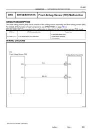
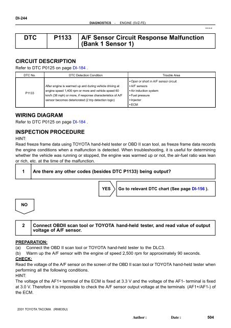
<strong>DTC</strong> <strong>P1133</strong> A/F <strong>Sensor</strong> <strong>Circuit</strong> <strong>Response</strong> <strong>Malfunction</strong><br />
(<strong>Bank</strong> 1 <strong>Sensor</strong> 1)<br />
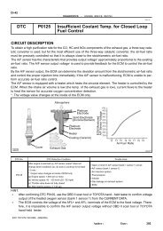
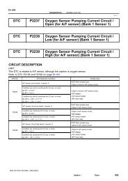
CIRCUIT DESCRIPTION<br />
Refer to <strong>DTC</strong> P0125 on page DI-184 .<br />
<strong>DTC</strong> No. <strong>DTC</strong> Detection Condition Trouble Area<br />
<strong>P1133</strong><br />
After engine is warmed up and during vehicle driving at<br />
engine speed 1,400 rpm or more and vehicle speed 60<br />
km/h (38 mph) or more, if response characteristics of A/F<br />
sensor becomes deteriorated (2 trip detection logic)<br />
Oper or short in A/F sensor circuit<br />
A/F sensors<br />
Air induction system<br />
Fuel pressure<br />
Injector<br />
ECM<br />
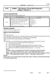
WIRING DIAGRAM<br />
Refer to <strong>DTC</strong> P0125 on page DI-184 .<br />
INSPECTION PROCEDURE<br />
HINT:<br />
Read freeze frame data using TOYOTA hand-held tester or OBD II scan tool, as freeze frame data records<br />
the engine conditions when a malfunction is detected. When troubleshooting, it is useful for determining<br />
whether the vehicle was running or stopped, the engine was warmed up or not, the air-fuel ratio was lean<br />
or rich, etc. at the time of the malfunction.<br />
1 Are there any other codes (besides <strong>DTC</strong> <strong>P1133</strong>) being output?<br />
YES Go to relevant <strong>DTC</strong> chart (See page DI-156 ).<br />
NO<br />
2 Connect OBDII scan tool or TOYOTA hand-held tester, and read value of output<br />
voltage of A/F sensor.<br />
PREPARATION:<br />
(a) Connect the OBD II scan tool or TOYOTA hand-held tester to the DLC3.<br />
(b) Warm up the A/F sensor with the engine of speed 2,500 rpm for approximately 90 seconds.<br />
CHECK:<br />
Read the voltage of the A/F sensor on the screen of the OBD II scan tool or TOYOTA hand-held tester when<br />
performing all the following conditions.<br />
HINT:<br />
The voltage of the AF1+ terminal of the ECM is fixed at 3.3 V and the voltage of the AF1- terminal is fixed<br />
at 3.0 V. Therefore it is impossible to check the A/F sensor output voltage at the terminals (AF1+/AF1-) of<br />
the ECM.<br />
2001 TOYOTA TACOMA (RM835U)<br />
Author:<br />
Date:<br />
504
DIAGNOSTICS<br />
-<br />
ENGINE (5VZ-FE)<br />
DI-245<br />
OK:<br />
Engine idling<br />
Engine racing<br />
Condition<br />
Driving at engine speed 1,500 rpm or more and vehicle<br />
speed 40 km/h (25 mph) or more, and operating throttle<br />
valve open and close.<br />
A/F <strong>Sensor</strong> Voltage Value<br />
Not remains at 3.30 V (0.660 V*)<br />
Not remains at 3.8 38V(076V*) (0.76 V*) or more<br />
Not remains at 2.8 V (0.56 V*) or less<br />
*: When using OBD II scan tool (excluding TOYOTA hand-held tester)<br />
HINT:<br />
Although there is a case that the output voltage of the A/F sensor is below 2.8 V (0.56 V*) during fuel<br />
enrichment, it is normal.<br />
Although there is a case that the output voltage of the A/F sensor is above 3.8 V (0.76 V*) during fuel<br />
cut, it is normal.<br />
If the output voltage of the A/F sensor remains at 3.30 V (0.660 V*) even after performing all the above<br />
conditions, the A/F sensor circuit may be open.<br />
If the output voltage of the A/F sensor remains at 3.8 V (0.76 V*) or more, or 2.8 V (0.56 V*) or less<br />
even after performing all the above conditions, the A/F sensor circuit may be short.<br />
*: With the OBD II scan tool (excluding TOYOTA hand-held tester).<br />
OK Go to step 8.<br />
NG<br />
3 Check for open and short in harness and connector between ECM and A/F sensor<br />
(See page IN-28 ).<br />
NG<br />
Repair or replace harness or connector.<br />
OK<br />
4 Check resistance of A/F sensor heater (See page SF-51 ).<br />
NG<br />
Replace A/F sensor.<br />
OK<br />
5 Check air induction system (See page SF-1 ).<br />
NG<br />
Repair or replace.<br />
2001 TOYOTA TACOMA (RM835U)<br />
Author:<br />
Date:<br />
505
DI-246<br />
DIAGNOSTICS<br />
-<br />
ENGINE (5VZ-FE)<br />
OK<br />
6 Check fuel pressure (See page SF-5 ).<br />
NG<br />
Check and repair fuel pump, pressure regulator,<br />
fuel pipe line and filter (See page SF-1 ).<br />
OK<br />
7 Check injector injection (See page SF-18 ).<br />
NG<br />
Replace injector.<br />
OK<br />
Replace A/F sensor.<br />
8 Perform confirmation driving pattern (See page DI-239 ).<br />
Go<br />
9 Is there <strong>DTC</strong> <strong>P1133</strong> being output again?<br />
YES Check and replace ECM (See page IN-28 ).<br />
NO<br />
10 Did vehicle run out of fuel in past?<br />
NO<br />
Check for intermittent problems (See page<br />
DI-146 ).<br />
2001 TOYOTA TACOMA (RM835U)<br />
Author:<br />
Date:<br />
506
DIAGNOSTICS<br />
-<br />
ENGINE (5VZ-FE)<br />
DI-247<br />
YES<br />
<strong>DTC</strong> <strong>P1133</strong> is caused by shortage of fuel.<br />
2001 TOYOTA TACOMA (RM835U)<br />
Author:<br />
Date:<br />
507
![F RELAY LOCATIONS [Engine Compartment] [Instrument Panel] 20](https://img.yumpu.com/53634281/1/184x260/f-relay-locations-engine-compartment-instrument-panel-20.jpg?quality=85)