The 2.5 clone papers - CCRMA
The 2.5 clone papers - CCRMA
The 2.5 clone papers - CCRMA

You also want an ePaper? Increase the reach of your titles
YUMPU automatically turns print PDFs into web optimized ePapers that Google loves.
<strong>The</strong> <strong>2.5</strong> <strong>clone</strong> <strong>papers</strong><br />
by Troels Gravesen<br />
troels.gravesen@danisco.com<br />
This is a compilation of former <strong>2.5</strong> <strong>clone</strong> files found at http://members.chello.se/jpo/<br />
• <strong>2.5</strong> <strong>clone</strong> measurements and construction, v5, page 2.<br />
• <strong>2.5</strong> <strong>clone</strong> without notch filter, page 24.<br />
• New tweeter for the <strong>2.5</strong> <strong>clone</strong>, Scan Speak 9500, page 26.<br />
• <strong>The</strong> final <strong>2.5</strong> <strong>clone</strong>, the sibilance problem, page 30.<br />
• <strong>The</strong> “new” 8535 drivers from Scan Speak, page 37.<br />
• <strong>The</strong> ProAc sound, page 41.<br />
Only a few changes have been made to the files, thus reflecting the project progression during the last 9 months of<br />
work on the Response <strong>2.5</strong> <strong>clone</strong>. New are some comments on the ProAc sound at page 41.<br />
Thanks to those who started the project and gathered the basic information needed to get it all going. Thanks to<br />
Paulie, US, for the basic crossover design. And thanks to all who reported their project on the web (a large number<br />
of links can be found at http://members.chello.se/jpo/. Without the inspiration from these people, this would never<br />
have evolved to such a long story.<br />
Thanks to Darryl Nixon, Australia, for all the discussions and constructive criticism. Without the help of Darryl and<br />
his “One Cloner’s Journey” found at http://www.diyaudio.com , we would not have had such a fruitful discussion<br />
on the merits and deficiencies of speakers in general and of the <strong>2.5</strong> <strong>clone</strong> in particular. <strong>The</strong>re will be different views<br />
on the “right sound” of the <strong>clone</strong>s, but only your ears can tell, what is best for you and your favorite music.<br />
If you have any questions regarding the project, you are welcome to address troels.gravesen@danisco.com<br />
Please refer to page numbers on specific questions.<br />
Aarhus, 28 th September, 2003.<br />
1
<strong>2.5</strong> <strong>clone</strong> measurements and construction, v5<br />
Hello, <strong>2.5</strong> <strong>clone</strong>rs!<br />
Thanks to all for the huge number of mails coming in from Canada, US, Australia, Hungary, Norway, Sweden, UK,<br />
Finland, Russia, Greece, New Zealand, etc. as response to these pages. And I cannot thank ‘JPO’ enough for<br />
lending me the space on his website. Thanks to all who wrote, and commented on the work. Without these mails<br />
the project would have ended another place.<br />
In this 5 th (!) version of my file I have added the construction of bass reflex enclosures with final measurements and<br />
comments. Initially the drivers were mounted in transmission line cabinets available, similar in size to the <strong>2.5</strong>s,<br />
making reliable measurements.<br />
I have had a lot of mails describing the benefits of adding the LCR circuit to the original design in order to get a<br />
more even frequency response but also with some regrets over loosing some of this immediate appealing<br />
‘technicolor’ sound of the originals.<br />
Some people have been confused over the increasing numbers of crossover designs; they want solutions, not<br />
options. For good reasons, they want to stay faithful to the original design and that’s fair enough. However, we<br />
cannot acquire the original drivers and we will never be able to make an exact copy of the originals. But reports<br />
from people comparing the <strong>clone</strong>s and the originals tell us that the <strong>clone</strong> can be just as good or even better.<br />
<strong>The</strong> crossover modifications are fairly simple and the choice is yours! <strong>The</strong> starting point is the crossover in fig. 1.<br />
This design can be added a LCR notch filter, fig. 14, and you can leave it here. <strong>The</strong> latest modification I have made<br />
were done to fine-tune frequency and phase response and has - in my opinion – improved midrange response but<br />
has minor impact on the overall perceived sound.<br />
Fig. 1 is the basic crossover (version 1) design I have<br />
been testing.<br />
Fig 1. Basic crossover, ‘version 1’.<br />
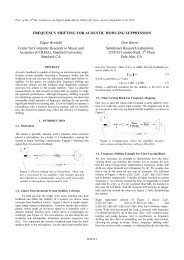
And here are the MLS measurements from the<br />
Stereophile magazine, as a target for designing the<br />
crossover.<br />
Fig 2: Stereophile measurements.<br />
I was excited to see if the 2 kHz bump would appear<br />
as predicted from Al.M’s writing at<br />
http://www.geocities.com/diyproac25/.<br />
<strong>The</strong> bump came out beautifully as seen from the<br />
graphs on page 2!<br />
2
3<br />
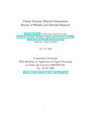
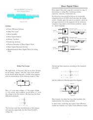
Tweeter polarity<br />
My first comment to the information available is on the discussion on tweeter polarity. It is suggested you try both<br />
options and choose what suits you the best.<br />
With same polarity of woofer and tweeter there will be a major dip in frequency response, which at the same time<br />
can be used to fine-tune the crossover.<br />
100.0<br />
dBSPL<br />
TGAudio MLS - Frequency Response 29-09-02 12.44.59<br />
90.0 108.0<br />
80.0 36.0<br />
70.0 -36.0<br />
60.0 -108.0<br />
50.0 -180.0<br />
200 1k 10k Hz 20k<br />
CH A dBSPL Unsmoothed 51.2kHz 16K Rectangular Start 1.88ms Stop 5.14ms FreqLO 306.59Hz<br />
red=3.3uF blue=4.5uF green=5.5uF yellow=6.8uF purple=8.3uF<br />
Fig 3: Polarity of tweeter.<br />
<strong>The</strong> tweeter certainly has to be connected with inverted polarity.<br />
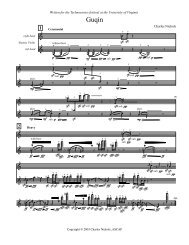
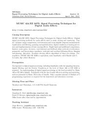
Measurements on LP-section, inductor L2 values:<br />
100.0<br />
dBSPL<br />
TGAudio MLS - Frequency Response 29-09-02 12.18.00<br />
90.0 108.0<br />
80.0 36.0<br />
70.0 -36.0<br />
60.0 -108.0<br />
50.0 -180.0<br />
300 1k 10k Hz 20k<br />
CH A dBSPL 1/3 Octave 51.2kHz 16K Rectangular Start 2.01ms Stop 5.12ms FreqLO 322.01Hz<br />
red=0.83mH blue=0.68mH green=0.47 mH yellow=0.27mH purple=none<br />
Fig 4. Initial measurements of 8535 with 0.83, 0.68, 0.47 and 0.27 mH inductor value of 2 nd inductor in LP section.<br />
Not much chance of getting rid of the 2 kHz bump without a LCR circuit. I does strike me however that that lowest<br />
value gives a response closer to the Stereophile measurements. Making the textbook LP crossover the response is<br />
40dB down at 7 kHz where the target seems to more like 40 dB down at 9 kHz.<br />
For the time being I stayed with the 0.83 mH. <strong>The</strong> 300-1500 Hz response is rather smooth which pleases me a lot.<br />
CLIO<br />
CLIO<br />
180.0<br />
Deg<br />
180.0<br />
Deg
Significance of value of capacitor in LP section.<br />
100.0<br />
dBSPL<br />
TGAudio MLS - Frequency Response 29-09-02 12.27.06<br />
90.0 108.0<br />
80.0 36.0<br />
70.0 -36.0<br />
60.0 -108.0<br />
50.0 -180.0<br />
300 1k 10k Hz 20k<br />
Fig. 5.<br />
CH A dBSPL 1/3 Octave 51.2kHz 16K Rectangular Start 2.01ms Stop 5.12ms FreqLO 322.01Hz<br />
red=6.8uF blue=7.5uF green=8.3uF yellow=9uF purple=10.1uF<br />
<strong>The</strong> value of this capacitor makes a fine instrument of changing crossover frequency.<br />
Significance of C1 in LP section on full range response.<br />
100.0<br />
dBSPL<br />
TGAudio MLS - Frequency Response 29-09-02 12.36.05<br />
90.0 108.0<br />
80.0 36.0<br />
70.0 -36.0<br />
60.0 -108.0<br />
50.0 -180.0<br />
300 1k 10k Hz 20k<br />
CH A dBSPL 1/3 Octave 51.2kHz 16K Rectangular Start 1.88ms Stop 5.14ms FreqLO 306.59Hz<br />
red=3.3uF blue=4.5uF green=5.5uF yellow=6.8uF purple=8.3uF<br />
Fig 6. MLS 0.33 oct. smoothing.<br />
8.3 uF seems to be a too high value, where 5.5 to 6.8 uF looks more appropriate but as seen from the curves this<br />
capacitor plays an important role in determining frequency response.<br />
Series resistor in HP section<br />
I would go for the 5R6 value, giving a quite flat frequency response. Going lower may give you an immediate<br />
appealing sound, but may add to listening fatigue in the long run. But this can be depending on room acoustics and<br />
listening distance.<br />
CLIO<br />
CLIO<br />
180.0<br />
Deg<br />
180.0<br />
Deg<br />
4
47 ohms resistor in HP section.<br />
In crossover diagrams available, the 47 ohms (R3) resistor is placed at different locations.<br />
1. on tweeter terminals<br />
2. before the 4.7 uF capacitor to ground<br />
<strong>The</strong> graph above demonstrates the (minor) significance of this resistor placement. I’ve chosen to place the resistor<br />
on tweeter terminals.<br />
100.0<br />
dBSPL<br />
TGAudio MLS - Frequency Response 29-09-02 22.09.35<br />
90.0 108.0<br />
80.0 36.0<br />
70.0 -36.0<br />
60.0 -108.0<br />
50.0 -180.0<br />
400 1k 10k Hz 20k<br />
CH A dBSPL 1/3 Octave 51.2kHz 16K Rectangular Start 1.62ms Stop 5.57ms FreqLO 253.47Hz<br />
tweeter 47R red= 47R 4.7uF<br />
Fig 8. Tweeter, MLS, 0.33 oct smoothing.<br />
Construction of notch filter for the 2 KHz bump:<br />
A LCR notch filter was designed to smooth the frequency response between 1500 and 3000 Hz consisting of<br />
1.5mH(0R35)+3.3 uF+10 ohm resistor.<br />
Fig. 9 displays the impact on 8535 response, MLS with no smoothing.<br />
100.0<br />
dBSPL<br />
TGAudio MLS - Frequency Response 06-10-02 18.24.29<br />
90.0 108.0<br />
80.0 36.0<br />
70.0 -36.0<br />
60.0 -108.0<br />
50.0 -180.0<br />
300 1k 10k Hz 20k<br />
CH A dBSPL Unsmoothed 51.2kHz 16K Rectangular Start <strong>2.5</strong>4ms Stop 5.61ms FreqLO 326.11Hz<br />
Fig.9. LP section +/- LCR and full range response with LCR.<br />
Notice that crossover target is only slightly affected and can easily be adjusted with C1. Fig.5.<br />
CLIO<br />
CLIO<br />
180.0<br />
Deg<br />
180.0<br />
Deg<br />
5
LCR impact on full range response<br />
100.0<br />
dBSPL<br />
TGAudio MLS - Frequency Response 06-10-02 17.59.22<br />
90.0 108.0<br />
80.0 36.0<br />
70.0 -36.0<br />
60.0 -108.0<br />
50.0 -180.0<br />
400 1k 10k Hz 20k<br />
CH A dBSPL 1/3 Octave 51.2kHz 16K Rectangular Start 2.46ms Stop 5.12ms FreqLO 376.47Hz<br />
Fig.10. Full range response +/- LCR, 0.33 oct. smoothing.<br />
90.0<br />
dBSPL<br />
TGAudio MLS - Frequency Response 06-10-02 17.56.08<br />
80.0 108.0<br />
70.0 36.0<br />
60.0 -36.0<br />
50.0 -108.0<br />
40.0 -180.0<br />
200 1k 10k Hz 20k<br />
CH A dBSPL Unsmoothed 51.2kHz 16K Rectangular Start 2.46ms Stop 5.12ms FreqLO 376.47Hz<br />
Fig. 11. Full range response + LCR, same and reverse polarity (no smoothing). 1 meter distance, tweeter height.<br />
CLIO<br />
CLIO<br />
180.0<br />
Deg<br />
180.0<br />
Deg<br />
6
Significance of LCR on cumulative spectral decay.<br />
TGAudio Waterfall 06-10-02 17.59.41<br />
0<br />
dB<br />
-5<br />
-10<br />
-15<br />
-20<br />
400 1k Hz 10k 20k CLIO<br />
Cumulative Spectral Decay<br />
Fig.12. 20 dB range CSD, without notch filter.<br />
TGAudio Waterfall 06-10-02 17.58.05<br />
0<br />
dB<br />
-5<br />
-10<br />
-15<br />
-20<br />
400 1k Hz 10k 20k CLIO<br />
Cumulative Spectral Decay<br />
Fig.13. 20 dB range CSD, with notch filter.<br />
<strong>The</strong> impact of the notch filter speaks for itself. With the LCR circuit in place an impressive + 1 dB frequency<br />
response is achieved between 300 and 4000 Hz, and the lack of the 2 kHz bump is clearly audible, where especially<br />
female voices gets a natural balance and acoustic guitars which may sound almost too good with the bump, now are<br />
presented with a much more realistic timbre. Listening to pink noise on the 8535 +/- LCR filter strongly suggests<br />
we get rid of the bump. Read Lynn Olson (Ariel) on the use of pink noise! http://www.alohaaudio.com/Arieltxt2.html#top<br />
And best of all, the 8535 does not loose its fresh and crisp presentation. <strong>The</strong> sound of the 8535 is hard to describe<br />
(isn’t sound always?), but certainly this is a very lucky/clever combination of the right matrix of paper pulp and<br />
carbon fiber, the right cone size and weight (the cone is more flexible that the 8545), voice coil dimensions, magnet<br />
size, all giving a smooth roll off characteristic and simplifying crossover design.<br />
2.7<br />
2.7<br />
1.8<br />
1.8<br />
0.9<br />
0.9<br />
0.0<br />
ms<br />
0.0<br />
ms<br />
7
Modified crossover, basic design + notch filter (version 2):<br />
Fig 14. Version 2 crossover.<br />
Fine tuning of crossover, version 3:<br />
In order to improve frequency and phase response I have modified the crossover and it looks like this. Red<br />
indicates changes.<br />
Fig 15. Version 3 crossover.<br />
Some people have made complaints on the crossover presentation and here is a more graphic presentation for biwiring.<br />
<strong>The</strong> components in the LCR circuit can be put together in any order,<br />
it does not matter! And be sure to have a decent distance between inductors - like 5 cm, in order to reduce<br />
interaction.<br />
8
Fig.16.<br />
System response with Fig. 14 (version 3) crossover:<br />
90.0<br />
dBSPL<br />
TGAudio MLS - Frequency Response 23-10-02 23.04.34<br />
80.0 108.0<br />
70.0 36.0<br />
60.0 -36.0<br />
50.0 -108.0<br />
40.0 -180.0<br />
300 1k 10k Hz 20k<br />
CH A dBSPL 1/3 Octave 51.2kHz 16K Rectangular Start 2.75ms Stop 5.29ms FreqLO 393.85Hz<br />
red=sensitivity, 2.83 V AC, 1 meter blue=min fase<br />
Fig.17. System response, version 3.<br />
Red/blue=left and right speaker.<br />
CLIO<br />
180.0<br />
Deg<br />
9
System impedance<br />
50.0<br />
Ohm<br />
TGAudio Sinusoidal 29-09-02 14.45.18<br />
40.0 108.0<br />
30.0 36.0<br />
20.0 -36.0<br />
10.0 -108.0<br />
0.0 -180.0<br />
10 100 1k 10k Hz 20k<br />
File: imp full range.sini<br />
CH A Ohm Unsmoothed Stepped Delay [ms] 0.000 Dist Rise [dB] 30.00<br />
Fig. 18. Impedance of full range (without notch filter) system.<br />
Not that much different from the Stereophile measurement, although it’s difficult to read the scale on the<br />
Stereophile scanning.<br />
<strong>The</strong> high damping of the lower impedance peak in the bass is caused by the stuffing of the transmission line and<br />
should be disregarded in this context.<br />
ScanSpeak 18W/8535-00<br />
Finally, here are the TS parameters of my 8535s: <strong>The</strong> data for the two units are remarkably alike, but the Qt is<br />
significantly higher that the promised 0.4!<br />
ScanSpeak data: Vas=69 litres, Qt= 0.38 and Fs= 26 Hz.<br />
My measurements: Vas = 44 litres, Qts= 0.52 and Fs= 34 Hz.<br />
ScanSpeak is using constant current method at high level, 36 mA, which may account for lack of correlation.<br />
My speaker calculation software says ~ 42 liters from the SS-data, my measurements suggests ~ 67 liters. Another<br />
software tells me this unit is best suited for a closed box!<br />
MANUFACTURER ScanSpeak ScanSpeak<br />
MODEL 18W8535-I 18W8535-II<br />
DATE 20-09-2002 20-09-2002<br />
Fs 33.9 34.8<br />
Qms 2.92 2.93<br />
Qes 0.63 0.63<br />
Qts 0.52 0.52<br />
VAS 43.9 43.1<br />
Mms 14.4 13.9<br />
BL 5.34 5.36<br />
dBSPL 86.3 86.6<br />
SD 0.0143 0.0143<br />
Re 5.88 5.94<br />
Fig.19. TS data.<br />
<strong>The</strong>se data were generated with my CLIO measurement system set at 0dB level. Adding another 0.4 ohm resistance<br />
(from inductors) in series with the woofer makes things even worse. <strong>The</strong> magnet on the 8535 seems to be too small<br />
for a 33-liter cabinet. Object for some tweaking!<br />
CLIO<br />
180.0<br />
Deg<br />
10
TS parameters at different measuring level:<br />
measuring level +10dB 0dB -10dB -20dB<br />
MANUFACTURER scanspeak scanspeak scanspeak scanspeak<br />
MODEL 18W8535 18W8535 18W8535 18W8535<br />
DATE 30-01-2003 30-01-2003 30-01-2003 30-01-2003<br />
Fs 32.37 35.16 36.65 37.35<br />
Re 5.86 5.86 5.86 5.86<br />
Rms 1.15 1.00 1.01 0.92<br />
Qms 2.64 2.96 3.47 3.72<br />
Qes 0.54 0.60 0.66 0.68<br />
Qts 0.45 0.50 0.55 0.58<br />
Cms 1.62 1.53 1.24 1.24<br />
Mms 14.96 13.41 15.24 14.68<br />
BL 5.74 5.36 5.60 5.44<br />
VAS 46.25 43.71 35.40 35.40<br />
Fig.21<br />
Series filters<br />
At http://audio<strong>clone</strong>.free.fr/ two series filters have been proposed and I have tried to wire up the circuits, and here<br />
are my measurements:<br />
Version 1:<br />
Fig. 22. Series filter #1.<br />
First of all a RC circuit has been placed at the crossover terminals which is a strange feature as it generally lowers<br />
the sensitivity of the whole system. I’ll show later the impact of this on frequency response.<br />
11
Frequency response, series filter #1, no RC circuit:<br />
100.0<br />
dBSPL<br />
TGAudio MLS - Frequency Response 07-12-02 23.44.15<br />
90.0 36.0<br />
80.0 -36.0<br />
70.0 -108.0<br />
60.0 -180.0<br />
50.0 -252.0<br />
200 1k 10k Hz 20k<br />
File: 95 cm MLS.mls<br />
CH A dBSPL 1/3 Octave 51.2kHz 16K Rectangular Start 2.68ms Stop 5.57ms FreqLO 345.95Hz<br />
red=95 cm hight blue=min phase<br />
Fig.23. Series filter #1, 1 meter distance, tweeter height. Red=freq.resp. blue=min.phase.<br />
When I first looked at this I thought I’d done a serious mistake and checked the setup several times. Couldn’t fine<br />
anything wrong. Minimum phase indicates serious problems and I tried same polarity of woofer and tweeter:<br />
Frequency response, series filter #1, no RC circuit, same polarity:<br />
100.0<br />
dBSPL<br />
TGAudio MLS - Frequency Response 08-12-02 00.02.17<br />
90.0 36.0<br />
80.0 -36.0<br />
70.0 -108.0<br />
60.0 -180.0<br />
50.0 -252.0<br />
200 1k 10k Hz 20k<br />
CH A dBSPL 1/3 Octave 51.2kHz 16K Rectangular Start 2.71ms Stop 5.57ms FreqLO 350.68Hz<br />
File: 95 cm MLS-same polarity.mls<br />
red=95 cm hight blue=min phase same polarity<br />
Fig.24. Series filter #1, same pol. Red = freq.resp., blue=min.phase<br />
Well, at least the major dip in frequency response at 2 kHz was gone, but the 2 kHz bump came to life again and<br />
min. phase still isn’t to pretty.<br />
I suppose the series filter was constructed with the intention of keeping inverted polarity of the drivers, so I went<br />
back to this and tried different measuring heights.<br />
Next is the response measured at 1 meter distance, microphone between tweeter and woofer:<br />
CLIO<br />
CLIO<br />
108.0<br />
Deg<br />
108.0<br />
Deg<br />
12
100.0<br />
dBSPL<br />
TGAudio MLS - Frequency Response 07-12-02 23.45.47<br />
90.0 36.0<br />
80.0 -36.0<br />
70.0 -108.0<br />
60.0 -180.0<br />
50.0 -252.0<br />
200 1k 10k Hz 20k<br />
File: 91 cm MLS.mls<br />
CH A dBSPL 1/3 Octave 51.2kHz 16K Rectangular Start 2.68ms Stop 5.57ms FreqLO 345.95Hz<br />
red=91 cm hight blue=min phase<br />
Fig.25, series filter #1, 1 meter distance, mic. between tweeter and woofer. Red=freq.resp., blue=min.phase.<br />
This turned out even worse, almost an 180 o phase shift at <strong>2.5</strong> kHz.<br />
I went back to measuring at tweeter height!<br />
Series filter #2, no RC circuit<br />
In this setup a 1 mH coil is introduced across the tweeter and there are minor modifications to the other<br />
components.<br />
Fig. 26. Series filter #2.<br />
CLIO<br />
108.0<br />
Deg<br />
13
Frequency response of series filter #2, no RC circuit:<br />
100.0<br />
dBSPL<br />
TGAudio MLS - Frequency Response 08-12-02 00.12.29<br />
90.0 36.0<br />
80.0 -36.0<br />
70.0 -108.0<br />
60.0 -180.0<br />
50.0 -252.0<br />
200 1k 10k Hz 20k<br />
File: series v2.mls<br />
CH A dBSPL 1/3 Octave 51.2kHz 16K Rectangular Start 2.71ms Stop 5.57ms FreqLO 350.68Hz<br />
red= v2 blue=min phase<br />
Fig.27. Series filter #2, no RC. Red= freq.resp., blue=min.phase.<br />
<strong>The</strong> serious dip in response at 2.3 kHz has been reduced slightly, but this is far from being an acceptable frequency<br />
response. And still there are serious phase problems.<br />
Impact of RC circuit on system response, series filter v.2:<br />
100.0<br />
dBSPL<br />
TGAudio MLS - Frequency Response 07-12-02 23.54.16<br />
90.0 36.0<br />
80.0 -36.0<br />
70.0 -108.0<br />
60.0 -180.0<br />
50.0 -252.0<br />
200 1k 10k Hz 20k<br />
CH A dBSPL 1/3 Octave 51.2kHz 16K Rectangular Start 2.68ms Stop 5.57ms FreqLO 345.95Hz<br />
File: plus-minus-RC.mls<br />
inverted polarity red=tweeter hight, no RC blue=tweeter hight, +RC<br />
Fig 28, System response, series filter #2, with/without RC circuit. Blue = with RC.<br />
<strong>The</strong> system response is generally lowered by 2 dB.<br />
<strong>The</strong> system response of the <strong>2.5</strong> <strong>clone</strong> is around 83 dB/2.83 V/1meter, which is pretty low. No reason to burn more<br />
energy in the RC circuit.<br />
CLIO<br />
CLIO<br />
108.0<br />
Deg<br />
108.0<br />
Deg<br />
14
Impedance of system with series filter #2, +/- RC circuit:<br />
50.0<br />
Ohm<br />
TGAudio Sinusoidal 08-12-02 00.24.24<br />
40.0 108.0<br />
30.0 36.0<br />
20.0 -36.0<br />
10.0 -108.0<br />
0.0 -180.0<br />
10 100 1k 10k Hz 20k<br />
File: imp v2+RC.sini<br />
CH A Ohm Unsmoothed Stepped Delay [ms] 0.000 Dist Rise [dB] 30.00<br />
red:v2 no RC blue:v2 +RC<br />
Fig. 29. Series filter, impedance, +/- RC circuit.<br />
Indeed the impedance is flattened to around 4 ohm above 100 Hz.<br />
My only comment to the RC circuit is that this must be a mistake.<br />
Well, those who might have been annoyed with the 2 kHz bump in the original design certainly eliminate this<br />
problem with the series filter, but this seems to introduce new and more serious problems. Frequency and phase<br />
responses are unacceptable and serious tweaking is necessary to get it right.<br />
<strong>The</strong> problem with series filters is that it’s difficult to measure the response of the individual drivers. John<br />
Kreskovskij has a method, but I haven’t tried it yet.<br />
http://www.geocities.com/kreskovs/Series-1.html<br />
I have only briefly done listening tests with the series filter but I find the dip at 2 kHz clearly audible and the<br />
tweeter far to loud for my taste.<br />
Replacing the drivers with 8 ohm resistors is not strictly correct but can give us an idea of what is going on.<br />
90.0<br />
dBSPL<br />
TGAudio MLS - Frequency Response 08-12-02 13.13.29<br />
80.0 108.0<br />
70.0 36.0<br />
60.0 -36.0<br />
50.0 -108.0<br />
40.0 -180.0<br />
200 1k 10k Hz 20k<br />
CH A dBSPL 1/3 Octave 51.2kHz 16K Rectangular Start 2.75ms Stop 5.55ms FreqLO 358.04Hz<br />
drivers replaced by 8R2 resistors<br />
Fig. 30.<br />
Red= frequency response of system with series filter.<br />
Blue= 8535 woofer with series filter.<br />
Green= 8513 tweeter with series filter.<br />
Purple= with resistor and capacitor for tweeter inverted, which gives a better response because now the capacitor<br />
‘sees’ a much more reasonable impedance.<br />
Yellow = system response with this modification.<br />
CLIO<br />
CLIO<br />
180.0<br />
Deg<br />
180.0<br />
Deg<br />
15
Fig 31. Part of series filter with inverted C and R for tweeter.<br />
With the suggested design the tweeter reaches down to 1500 Hz giving serious phase problems in the crossover<br />
region.<br />
Inverting the resistor and capacitor helps a lot, but there are months of work to get it right!<br />
Conclusion on series filters:<br />
<strong>The</strong> series filter has a less than acceptable frequency response, serious phase problems and cannot be<br />
recommended.<br />
And don’t place a RC circuit on top of the whole crossover, this way you will just burn energy and reduce system<br />
efficiency, which is so much needed.<br />
16
Construction of bass reflex cabinets:<br />
A lot of cabinet construction <strong>papers</strong> have been published and I won’t go into much detail about this.<br />
I have maintained the internal volume but outer dimensions have been changed to 20 x 26.5 x 100 cm and the<br />
bottom plate have been lifted to give room for the crossover to be placed externally. This way it’s easy to make<br />
changes, and the components are not affected by vibration from the driver. <strong>The</strong> tweeter has it’s own sealed back<br />
chamber in order to reduce vibrations from the woofer. Cross bracing has been added to reduce cabinet resonance.<br />
Cabinets are constructed from 20 mm pre-veneered MDF and front panels are 25 mm (15 mm solid mahogany + 10<br />
mm MDF). Internal bracing is 10 mm MDF.<br />
Fig 32. Cabinets partly assembled.<br />
All walls are damped with 10 mm heavy polyester foam (glued to the panels) and a mixture of polyester and lambs<br />
wool available from Monacor is used for further damping.<br />
Right behind the 8535 several layers of the lambs wool is placed in order to reduce standing waves hitting back on<br />
the membrane.<br />
Deflex damping material is to my knowledge not available in Denmark (?).<br />
Some more pictures:<br />
Fig.33, <strong>2.5</strong>-crossover.<br />
Cored 1.8 mH coil and air-cored 0.47 mH, both
Fig. 34, front plate.<br />
Fig.35, back side of front plate.<br />
Fig.36, damping material.<br />
Fig.37, CO at base plate.<br />
18
At last, the final cabinets with drivers, first play in my workshop; why is it that I after just a couple of months<br />
forget how many hours it takes to build a pair of cabinets!?<br />
Fig 38. First time setup in my workshop.<br />
Crossovers, the never ending story…<br />
- and short presentation of features:<br />
1. <strong>The</strong> ‘original’ design, version 1 (fig.1)<br />
You are likely to have a major bump at 2 kHz, which sounds very well on certain recordings but makes voices and<br />
violins intolerable. Darryl from Australia calls this the ‘technicolor sound’ and that is just what it is.<br />
2. Original design + LCR, version 2 (fig 14)<br />
You get rid of the 2 kHz bump and can enjoy a wider spectrum of recordings. Enhanced three-dimensionality and<br />
lots of space.<br />
3. Modified crossover + modified LCR, version 3 (fig15)<br />
An even flatter frequency and improved phase response in the critical upper midrange. <strong>The</strong> choice is yours.<br />
Having finished my bass reflex enclosures I have wired up the three crossover (CO) versions again and was excited<br />
to see whether I could reproduce my measuring results 2-3 months ago! And it didn’t turn out too bad. All<br />
measurements performed at 1 meter distance, tweeter height.<br />
<strong>The</strong> Stereophile review suggests we have a crossover point of 3200-3300 Hz, where the version 1 gives 3000-3100<br />
Hz, slightly below the original. <strong>The</strong> version 3 displays a crossover point of 3350 Hz. However, no need to be exited<br />
about +/- 100 Hz. <strong>The</strong> aim of the v3 crossover was to create a less steep roll-off as seen on the Stereophile<br />
measurements. <strong>The</strong> 8535 driver is down 40-45dB at 8.5 kHz where we - with the v1 crossover - reach this level<br />
already at 7 kHz. It has been suggested that the OEM-8535 has less carbon fiber and a more flexible membrane<br />
than the ‘DIY’ units. This could mean enhanced high frequency response and a smoother roll-of performance. <strong>The</strong><br />
problem with having a notch filter at 2 kHz is that it is so close to the crossover point, that it’s impact is stretched<br />
over the crossover region. I have tried a notch-filter acting exactly in the 1500-2500 Hz region, but this didn’t<br />
perform well.<br />
Fig. 39 and fig. 40 displays the 8535 performance with the v2 and v3 filter +/- notch filter.<br />
Fig. 41 and fig. 42 displays the overall performance of drivers with same and inverted polarity and tells us that we<br />
have a very good phase correlation between drivers in both cases. <strong>The</strong> v3 has a more symmetrical >20 dB null at<br />
crossover point with same polarity. <strong>The</strong> 8535 with the v2 CO has a very abrupt, linear and steep roll-off behavior.<br />
19
90.0<br />
dBSPL<br />
MLS - Frequency Response 14-02-03 18.35.47<br />
80.0 108.0<br />
70.0 36.0<br />
60.0 -36.0<br />
50.0 -108.0<br />
40.0 -180.0<br />
300 1k 10k Hz 20k<br />
CH A dBSPL 1/3 Octave 51.2kHz 16K Rectangular Start <strong>2.5</strong>6ms Stop 5.53ms FreqLO 336.84Hz<br />
<strong>2.5</strong> crossover v2 1.8mH/7.4uF/0.83mH 3.3uF/10R/1.5mH<br />
Fig. 39. <strong>2.5</strong> crossover, v2, red: + LCR, blue: no LCR<br />
90.0<br />
dBSPL<br />
CLIO<br />
MLS - Frequency Response 14-02-03 20.06.26<br />
80.0 108.0<br />
70.0 36.0<br />
60.0 -36.0<br />
50.0 -108.0<br />
40.0 -180.0<br />
300 1k 10k Hz 20k<br />
CH A dBSPL 1/3 Octave 51.2kHz 16K Rectangular Start <strong>2.5</strong>6ms Stop 5.53ms FreqLO 336.84Hz<br />
crossover v2 LP:1.8mH/6.8uF/0.83mH LCR:3.3uF/10R/1.5mH HP:5R6-3.3uF/0.25mH/4.7uF-47R CO-point=3100Hz reverse/same pola<br />
Fig. 41. <strong>2.5</strong> crossover, v2, all drivers, polarity<br />
Crossover point = 3100 Hz<br />
0.33 oct. Smoothing. Same polarity, no smoothing<br />
Frequency response of <strong>2.5</strong> with CO v2 and v3<br />
90.0<br />
dBSPL<br />
CLIO<br />
MLS - Frequency Response 14-02-03 20.32.42<br />
80.0 108.0<br />
70.0 36.0<br />
60.0 -36.0<br />
50.0 -108.0<br />
40.0 -180.0<br />
300 1k 10k Hz 20k<br />
CH A dBSPL 1/3 Octave 51.2kHz 16K Rectangular Start <strong>2.5</strong>6ms Stop 5.53ms FreqLO 336.84Hz<br />
<strong>2.5</strong> crossover v2 and v3 full range response and min. phase green/purple=v2 red/blue=v3<br />
Fig. 43.Green/purple(min.ph) = v2, Red/blue(min.ph)<br />
= v3<br />
CLIO<br />
180.0<br />
Deg<br />
180.0<br />
Deg<br />
180.0<br />
Deg<br />
90.0<br />
dBSPL<br />
MLS - Frequency Response 14-02-03 18.06.30<br />
80.0 108.0<br />
70.0 36.0<br />
60.0 -36.0<br />
50.0 -108.0<br />
CH A dBSPL Unsmoothed 51.2kHz 16K Rectangular Start 2.75ms Stop 5.53ms FreqLO 360.56Hz<br />
<strong>2.5</strong> crossover v3 1.8mH/6.8uF/0.47mH 2.2uF/10R/1.5mH<br />
20<br />
40.0 -180.0<br />
200 1k 10k Hz 20k<br />
Fig. 40. <strong>2.5</strong> crossover, v3, red: + LCR, blue: no LCR<br />
90.0<br />
dBSPL<br />
CLIO<br />
MLS - Frequency Response 14-02-03 20.11.58<br />
80.0 108.0<br />
70.0 36.0<br />
60.0 -36.0<br />
50.0 -108.0<br />
40.0 -180.0<br />
300 1k 10k Hz 20k<br />
CH A dBSPL Unsmoothed 51.2kHz 16K Rectangular Start <strong>2.5</strong>6ms Stop 5.53ms FreqLO 336.84Hz<br />
crossover v2 LP:1.8mH/6.8uF/0.47mH LCR:2.2uF/10R/1.5mH HP:5R6-3.9uF/0.22mH/4.7uF-47R CO-point=3400Hz reverse/same pola<br />
Fig.42. <strong>2.5</strong> crossover, v3, all drivers, polarity<br />
Crossover point = 3350 Hz<br />
0.33 oct. Smoothing. Same polarity, no smoothing<br />
Frequency response of CO v3 at 1 and 2 meters<br />
100.0<br />
dBSPL<br />
CLIO<br />
MLS - Frequency Response 14-02-03 23.31.35<br />
90.0 108.0<br />
80.0 36.0<br />
70.0 -36.0<br />
60.0 -108.0<br />
50.0 -180.0<br />
300 1k 10k Hz 20k<br />
CH A dBSPL Unsmoothed 51.2kHz 16K Rectangular Start 5.74ms Stop 6.91ms FreqLO 853.33Hz<br />
<strong>2.5</strong> response tweeter height red=1 meter blue=2 meter purple=same pol. 2 m, <strong>2.5</strong> cm above tweeter height<br />
Fig. 44. Red=1m, blue=2m, purple=same pol.<br />
CLIO<br />
180.0<br />
Deg<br />
180.0<br />
Deg<br />
180.0<br />
Deg
100.0<br />
dBSPL<br />
MLS - Frequency Response 15-02-03 21.44.47<br />
90.0 108.0<br />
80.0 36.0<br />
70.0 -36.0<br />
60.0 -108.0<br />
50.0 -180.0<br />
300 1k 10k Hz 20k<br />
CH A dBSPL 1/3 Octave 51.2kHz 16K Rectangular Start 2.81ms Stop 5.45ms FreqLO 379.26Hz<br />
blue=left speaker red=right speaker sensitivity 2.83Vrms<br />
Fig.45. Freq. Response left and right speaker.<br />
Sensitivity at 1 meter, 2.83 Vrms, ~ 83 dB.<br />
For comparison here are fresh Rogers LS3/5a (11<br />
ohm version) frequency response curves, with and<br />
without front grille. A legendary loudspeaker with<br />
phase problems in the crossover region that today<br />
would make any home constructor ashamed of<br />
himself. I keep these shoeboxes to remind myself of<br />
not overemphasizing any single parameter in<br />
loudspeaker construction because they sound so<br />
good.<br />
100.0<br />
dBSPL<br />
CLIO<br />
MLS - Frequency Response 15-02-03 21.31.53<br />
90.0 108.0<br />
80.0 36.0<br />
70.0 -36.0<br />
60.0 -108.0<br />
50.0 -180.0<br />
300 1k 10k Hz 20k<br />
CH A dBSPL 1/3 Octave 51.2kHz 16K Rectangular Start 2.87ms Stop 5.53ms FreqLO 376.47Hz<br />
LS35A red:+front blue:-front<br />
Fig.46. Rogers LS3/5a, 11 ohm version, 1989.<br />
100.0<br />
dBSPL<br />
CLIO<br />
MLS - Frequency Response 15-02-03 21.51.31<br />
90.0 1.000<br />
80.0 0.600<br />
70.0 0.200<br />
60.0 -0.200<br />
50.0 -0.600<br />
300 1k 10k Hz 20k<br />
CH A dBSPL 1/3 Octave 51.2kHz 16K Rectangular Start 2.81ms Stop 5.66ms FreqLO 350.68Hz<br />
red=0 blue=10 green=20 purple=30<br />
Fig. 47. CO v3 horizontal response,<br />
0(red),10(blue),20(green)30 o (purple)<br />
CLIO<br />
180.0<br />
Deg<br />
180.0<br />
Deg<br />
1.400<br />
ms<br />
21<br />
Well, whether you choose v2 or v3 crossover you<br />
will get a great speaker in any case.<br />
Be sure to use the right component values in either<br />
case. <strong>The</strong> most important components are the<br />
capacitor in the LP section, 7.4 uF for v2 and 6.8 uF<br />
for V3, the coil in the HP section, 0.25 mH for v2 and<br />
0.22 mH for v3 and finally the capacitor in the LCR<br />
circuit, 3.3 uF for v2 and 2.2 uF for v3.<br />
I am very happy for the evaluation given by Darryl in<br />
Australia and with his permission, here are his<br />
comments:<br />
I finally got around to experimenting with resistor<br />
value increases in the notch filter, which you<br />
suggested might restore some of the "life" or<br />
"technicolour" sound to your latest (final?) crossover<br />
version.<br />
Increasing the resistor to 12 ohms does do this to<br />
some small extent I guess, but any greater value<br />
begins to re-introduce the upper midrange glare<br />
quite audibly (to my ears, anyway). All things<br />
considered, I still prefer the sound with the 10 ohm<br />
value, i.e. an optimally flat response in the 2 KHz<br />
area.<br />
I did find that reducing the resistor on the tweeter<br />
from 5.6 ohms back down to 5 ohms produced quite<br />
an improvement - I should have tried this before -<br />
and restored much of that distinctive Proac sound,<br />
more so than I would have expected. (With the<br />
standard (Jacq) crossover + notch filter, I preferred<br />
the 5.6 ohms you recommend.) Increasing the tweeter<br />
output in your latest crossover makes it a lot harder<br />
to choose between the two versions. Even with<br />
increased tweeter level, sibilance is still better<br />
controlled and the midrange sounds more realistic<br />
than it does with the Jacq version + notch filter. I<br />
think I'll stay with your latest version for the time<br />
being, albeit with slightly increased treble. That<br />
change has swung things the other way for me. It<br />
seems a good compromise in my system, and 90 per<br />
cent of the time it sounds wonderful.<br />
Incidentally, the listening tests I've been carrying out<br />
have been with a Dynaco PAS3X/Stereo 70 valve<br />
preamp and amp. I also have a Sugden C51/P51<br />
solid state combo, but it's off for repair at the<br />
moment.
I was curious to see what would happen with a mid-fi<br />
solid state amp, so borrowed a friend's NAD 1155<br />
preamp and Rotel RB-981 power amp. <strong>The</strong>re is no<br />
doubt in my mind that the Proac is best suited to<br />
valve amplification. With this solid state set-up, there<br />
was a definite "hardness" in the midrange which was<br />
easily provoked by the wrong recording. Sibilance<br />
also became more of a problem. <strong>The</strong> sound was also<br />
quite "dry" and occasionally harsh, though bass<br />
depth and definition was astoundingly good. (A<br />
Superphon Revelation Basic Preamp did improve<br />
things at the top end.) Nevertheless, the speaker<br />
seemed a lot more tolerant of this set-up with your<br />
latest crossover than with the Jacq + notch filter. My<br />
own Sugden (although no longer young) works far<br />
better, having more valve-like warmth and a much<br />
superior presentation all round, though not as good<br />
as the Dynaco.<br />
To my mind, the Proac Response <strong>2.5</strong> is a seriously<br />
good but extremely fussy speaker, easily provoked<br />
into sounding less than wonderful. <strong>The</strong> bass-mid is<br />
very transparent to the source, and can easily stray<br />
into hardness with inadequate SS amplification, discreproduction<br />
equipment or poor recordings. (I do<br />
wonder whether that hardness is in part due to cone<br />
break-up, albeit at a low level thanks to your notch<br />
filter.)<br />
Another problem is the tweeter, which can easily<br />
stray into excessive sibilance with the wrong<br />
recording, though your latest crossover mods go a<br />
long way towards eliminating this. Yet another<br />
problem is a lack of energy in the lower<br />
midrange/upper bass, which seems to be roomboundary<br />
related. Careful positioning and a warmsounding<br />
amp can minimise this, but it seems<br />
impossible to cure completely.<br />
I guess I'm being over-critical, given the Proac's<br />
price-point. – and all "high-end" equipment is fussy.<br />
Nevertheless, this is the best speaker I have ever<br />
owned and pretty easy to live with - and it now works<br />
very well in my system. I just wonder how many<br />
people out there are disappointed due to matching<br />
problems in their systems!<br />
Final evaluation<br />
This is probably the most tough part of it all having<br />
to express sonic qualities in a foreign language.<br />
But I’ll give it a shot….<br />
This is probably my 5 th floorstander of this design<br />
being bass reflex or transmissionline constructions,<br />
all two-way designs of approx. 20x25x100 cm in size<br />
with SS8545+9500, Vifa PL18+XT25, Vifa<br />
M18WO+D27, etc.<br />
My setup consists of a ROTEL CD modified with<br />
goodies from LCAudio, a CT101 audio buffer from<br />
22<br />
DanishAudioConnecT (www.dact.com) and a<br />
LCAudio, non-feedback 120 W power amplifier,<br />
Millenium edition (www.lcaudio.dk).<br />
Listening sessions, version 3 crossover.<br />
First disc was Charlie Haden & Pat Metheny:<br />
Missiouri Sky.<br />
It's been a couple of months since I had my initial<br />
transmission lines running and the final setup with<br />
the reflex boxes by far exceeded my expectations.<br />
<strong>The</strong> bass is significantly better in the reflex boxes and<br />
I had to remove things from my living room that do<br />
not use to rattle with my ‘reference’ system! I can't<br />
believe they go this deep! A tiny 6½" woofer! <strong>The</strong><br />
midrange is clear, crisp and transparent and listening<br />
to acoustic music it's very, very good. On track two<br />
the guitar is very closely miked with a lot of low-end<br />
information and the bass attack is most impressive.<br />
<strong>The</strong> tonal balance seems to favor the highs and<br />
listening to female jazz-singers, strings and big-band<br />
music was not so impressive! ‘S’-sounds and ‘T’sounds<br />
are much to pronounced and the tonal balance<br />
of violins are simply not correct compared to my<br />
‘reference’ where voices can be played at loud<br />
volume without distress. <strong>The</strong> phenomenon is called<br />
sibilance!<br />
Tried to unplug the tweeter and played the 8535 at<br />
loud levels and everything sounds fine except that<br />
you miss the tweeter. <strong>The</strong> problem doesn’t seem to<br />
come from here.<br />
Another comment from Darryl:<br />
Do you also find a lack of energy in the lower<br />
midrange/upper bass? My own <strong>clone</strong>s sound<br />
beautifully warm provided there are deep lows in the<br />
recording, but if not, they can sound quite "dry".<br />
Yes and no. I can’t say that I have experienced any<br />
lack of energy or level in upper bass register and I<br />
believe actual room acoustics plays an important role<br />
here. On the other hand I like a speaker that has a<br />
very dry sound. I’ve done a lot to reduce vibrations in<br />
my cabinets and this probably helps a lot in providing<br />
a dry sound. I don’t feel any vibrations on sides, front<br />
and back of the cabinet, but strangely enough on the<br />
top plate and I’ll have to ad additional material to<br />
eliminate this.
Let’s take another look at the frequency response:<br />
90.0<br />
dBSPL<br />
MLS - Frequency Response 16-02-03 18.50.08<br />
80.0 108.0<br />
70.0 36.0<br />
60.0 -36.0<br />
50.0 -108.0<br />
40.0 -180.0<br />
200 1k 10k Hz 20k<br />
CH A dBSPL 1/3 Octave 51.2kHz 16K Rectangular Start 2.70ms Stop 5.55ms FreqLO 350.68Hz<br />
Fig.48. Value of tweeter series resistor<br />
Green=5R6<br />
Yellow=8R2 (sorry for the yellow, hope it’s visible)<br />
Purple=10R<br />
Usually I try to target the BBC-dip curve, giving a ~2<br />
dB dip in the upper midrange/lower highs usually<br />
giving a slightly more distant perspective, but an<br />
overall more balanced sound. <strong>The</strong> response of the<br />
<strong>clone</strong>s do not exactly meet this criteria. We have a<br />
rather flat midrange response and it better be good<br />
with this level.<br />
Fig. 48 graphs are showing the response at 2.83Vrms<br />
(measured at speaker terminals) and from 0.3-3.5<br />
kHz we have a very flat response of +/- 1 dB. Quite<br />
impressive. But from 4-17 kHz we are least 2 dB<br />
higher and from another construction I learned that<br />
this could make a world of difference. I have worked<br />
a lot with the 8512 tweeter supplementing an ETON<br />
4-300 midrange and this – when properly balanced –<br />
works very well. <strong>The</strong> 4-300 is a very revealing<br />
midrange driver and matching this driver with a<br />
slightly too highly pitched tweeter makes it<br />
intolerable to listen to.<br />
Maybe the 8512 and –13 isn’t that well suited to<br />
work with the much larger 8535 woofer/midrange<br />
cone. I would like to try the HIQUPHON OW1tweeter<br />
without magnetic oil (and probably more<br />
heavily coated) and produced to very close tolerances<br />
with reported low distortion and coloration and an<br />
impressive CSD.<br />
Changing the tweeter series resistor to 8R2 or 10R<br />
seems to correct things and I stayed with 8R2<br />
because with 10R I would have to go through another<br />
fine-tuning of the HP section because it changes the<br />
crossover point to 3.7 kHz and creates a 1.5 dB dip at<br />
~3.5 kHz.<br />
It helped a great deal on the above mentioned<br />
problems although there are still recordings were they<br />
fall short compared to my ‘reference’.<br />
CLIO<br />
180.0<br />
Deg<br />
23<br />
It’s a gut feeling, that the 8513 may not be the one<br />
to pick if you want a more true presentation of the<br />
upper register of most instruments and voices. It has<br />
some intrinsic values in terms of speed and<br />
‘sparkling’ sound, and possibly we can turn this<br />
speaker into something that will split constructors<br />
into two groups. One group that wants to stay true to<br />
the original design with its limitations in terms of not<br />
being able to obtain the ‘real’ OEM-drivers and<br />
another group that will take the best of the 8535’s<br />
deep bass capabilities and midrange clarity and<br />
combine it with a tweeter that supplements these<br />
virtues with more fidelity.<br />
Best regards<br />
Troels Gravesen<br />
troels.gravesen@danisco.com<br />
PS, 30.03.2003<br />
Have tried the OWI tweeters and except for size and<br />
sensitivity they can immediately replace the 8513,<br />
but the response turns out even flatter than with the<br />
8513s and the sound wasn’t so good. After some<br />
tweaking, I decided this would require a new<br />
crossover and tempting as it was, this is not the time.<br />
<strong>The</strong> OWIs measures the best I have ever experienced.<br />
Ruler flat from 1 kHz to 20 kHz! Can’t wait to<br />
incorporate these in some future design.
<strong>The</strong> <strong>2.5</strong> <strong>clone</strong> without notch filter<br />
Sometimes it takes a journey to get back to your<br />
starting point and see what is the real problem in<br />
front of you.<br />
This being the case with the <strong>2.5</strong> <strong>clone</strong> and the 2 kHz<br />
bump created by the 8535 driver itself and the<br />
crossover topology. One person at diyaudio.com<br />
working with active crossovers for the <strong>clone</strong> even<br />
predicted that there should be a bump at 2 kHz<br />
derived from the crossover.<br />
In my latest paper at http://members.chello.se/jpo/<br />
(New <strong>2.5</strong> <strong>clone</strong> tweeter, crossover and speaker<br />
setup) I have constructed a new crossover for<br />
implementing the ScanSpeak D2905-9500 tweeter.<br />
By starting all over again with the crossover it was<br />
obvious to experiment with the Q of the parallel<br />
capacitor in the LP-section. In order to get the target<br />
point of crossover and the target roll-off<br />
characteristic a RC circuit was added. It appeared that<br />
no notch filter was needed.<br />
When this was done it was obvious to try to apply<br />
this approach to the 8535+8513 drivers for those who<br />
want to maintain the 8513 tweeter.<br />
Initial measurements of 8535 driver:<br />
90.0<br />
dBSPL<br />
TGAudio MLS - Frequency Response 07-04-03 19.54.51<br />
80.0 108.0<br />
70.0 36.0<br />
60.0 -36.0<br />
50.0 -108.0<br />
40.0 -180.0<br />
200 1k 10k Hz 20k<br />
CH A dBSPL 1/3 Octave 51.2kHz 16K Rectangular Start 2.75ms Stop 5.74ms FreqLO 334.64Hz<br />
red= +1.8 mH blue= +1.8mH/7.4uF/0.83mH green=+1.8mH/6.8uF+3R3/0.47 mH<br />
Fig.1. 8535 driver SPL response, 0.33 oct.<br />
smoothing.<br />
Blue = 8535 driver with v1 crossover: 1.8 mH//47R +<br />
7.4 uF + 0.83 mH<br />
Red = 8535 driver + 1.8 mH<br />
Green = 8535 driver with new crossover: 1.8mH +<br />
(6.8uF+3R3) + 0.47 mH<br />
As seen from the graphs it is possible to eliminate the<br />
notch filter by adding a resistor to the capacitor. That<br />
simple!<br />
And the point of crossover can still be adjusted by the<br />
capacitor value (data not shown).<br />
I have tried to maintain all component values in the<br />
new design to minimise the cost of the change. This<br />
CLIO<br />
180.0<br />
Deg<br />
24<br />
modification refers to the ‘version 3’ crossover<br />
found in ‘<strong>2.5</strong> <strong>clone</strong> measurements and construction,<br />
v5’ at http://members.chello.se/jpo/.<br />
And it implies the use of DAMAR coating as<br />
described in 8535+9500 paper. However, I’m<br />
confident that this modification will also work fine<br />
without the DAMAR coating.<br />
90.0<br />
dBSPL<br />
TGAudio MLS - Frequency Response 07-04-03 20.27.34<br />
80.0 108.0<br />
70.0 36.0<br />
60.0 -36.0<br />
50.0 -108.0<br />
40.0 -180.0<br />
200 1k 10k Hz 20k<br />
CH A dBSPL 1/3 Octave 51.2kHz 16K Rectangular Start 3.24ms Stop 6.04ms FreqLO 358.04Hz<br />
red= +1.8 mH blue= +(1.8mH-47R)/(7.4uF)/(0.83mH) green=+(1.8mH-47R)/(6.8uF+3R3)/(0.47 mH)<br />
Fig.2. Driver response, 0.33 oct. smoothing.<br />
As seen from the graphs the result is a smooth<br />
midrange response, and the level can be adjusted to<br />
personal taste by changing the value of the resistor in<br />
the in LP section, fig. 3.<br />
90.0<br />
dBSPL<br />
TGAudio MLS - Frequency Response 07-04-03 20.43.17<br />
80.0 108.0<br />
70.0 36.0<br />
60.0 -36.0<br />
50.0 -108.0<br />
40.0 -180.0<br />
200 1k 10k Hz 20k<br />
CLIO<br />
CH A dBSPL 1/3 Octave 51.2kHz 16K Rectangular Start 3.38ms Stop 6.04ms FreqLO 376.47Hz<br />
green=2R2 red=3R3 blue=4R7<br />
Fig.3. Value of R in LP section.<br />
Green = 3R3, red = 4R7, blue = 5R6. I recommend<br />
3R3.<br />
Crossover changes:<br />
• <strong>The</strong> 47R resistor parallel to the 1.8 mH<br />
inductor removed.<br />
• <strong>The</strong> 6.8 uF capacitor is added a 3.3 ohm<br />
resistor.<br />
• LCR notch filter is removed.<br />
• No changes to the HP-section.<br />
180.0<br />
Deg<br />
CLIO<br />
180.0<br />
Deg
<strong>2.5</strong> <strong>clone</strong> crossover, version 6. Tweeter level<br />
Fig. 4. crossover, v6.<br />
(I’m sorry for having to call this version #6, but there<br />
have been a number of designs in between, and I<br />
have to keep track of all changes).<br />
Here’s a graphic presentation for bi-wiring:<br />
Fig.5, crossover, v6<br />
90.0<br />
dBSPL<br />
25<br />
TGAudio MLS - Frequency Response 07-04-03 20.48.50<br />
80.0 108.0<br />
70.0 36.0<br />
60.0 -36.0<br />
50.0 -108.0<br />
40.0 -180.0<br />
200 1k 10k Hz 20k<br />
CH A dBSPL 1/3 Octave 51.2kHz 16K Rectangular Start 3.38ms Stop 6.04ms FreqLO 376.47Hz<br />
red=4R7 blue=5R6 green=8R2<br />
Fig.6. Tweeter series resistor, red = 5R6, blue = 6R8,<br />
green = 8R2. I use 8R2.<br />
<strong>The</strong> choice is yours.<br />
CLIO<br />
180.0<br />
Deg
New tweeter for the <strong>2.5</strong> <strong>clone</strong><br />
After introducing the 2 kHz notch filter to the<br />
original crossover (v2) design and also introducing a<br />
slightly modified filter (v3) in order to smooth<br />
frequency and phase response in the upper midrange,<br />
still people have been complaining about the sibilant<br />
nature of the upper registers. I have defended the<br />
8513 tweeter, being such a proven design, and have<br />
hesitated to make any changes to the tweeter as this<br />
would most certainly for good take us away from the<br />
ProAc Response <strong>2.5</strong> sound with its strengths and<br />
weaknesses.<br />
However, I cannot ignore the fact that a number of<br />
my recordings linger on my CD-shelf as long as the<br />
<strong>clone</strong>s are in place in my living room, this mostly<br />
being records of vocal music.<br />
But first a short story on the tweaks that have been<br />
conducted in order to get to the decision of<br />
introducing a new tweeter.<br />
DAMAR coating<br />
A series of near field measurements of the 8535 were<br />
done in order to localize cone break-up and not<br />
surprisingly the dust cap is responsible for some<br />
serious cone break-ups that create a significant bump<br />
at 2 kHz (fig. 1) (same place as the bump created by<br />
the crossover).<br />
Two layers of DAMAR coating were applied to the<br />
center dome and this to some extent smoothed the<br />
frequency response in the upper midrange (fig. 2) and<br />
also above 10 kHz. Subjectively this had a positive<br />
effect on the overall perceived sound.<br />
Damping the 8535 Dust Cap (diyaudio.com), Darryl<br />
Nixon and Troels Gravesen.<br />
Recent experiments by Troels Gravesen have<br />
demonstrated that there are advantages in applying<br />
damping to the dust cap of the <strong>clone</strong>'s 8535 mid-bass<br />
driver. Troels has been working on the resonance<br />
problems of the 8535 which he found has "a major<br />
intrinsic bump at 3 KHz". In Troels' words, “. . . the<br />
coating seems to remove some edginess in the<br />
midrange with a more smooth performance and<br />
tolerance towards difficult recordings".<br />
<strong>The</strong> substance used is Damar varnish, which can be<br />
obtained from artists' supply shops. <strong>The</strong> picture<br />
attached is from Troels and is of Damar as sold in<br />
Denmark. <strong>The</strong> following is reported with Troels'<br />
permission, together with quotes from his e-mails to<br />
me.<br />
"As a start you may apply a coating until the dust cap<br />
is soaked and leave it there as long as it is not<br />
applied outside the dust cap. <strong>The</strong> effect should be<br />
there in a couple of hours . . .<br />
26<br />
"At the beginning of applying the DAMAR the<br />
somewhat porous dust cap readily absorbs the<br />
varnish and I continued to apply DAMAR until the<br />
surface appeared shining. This doesn't mean 'flooded'<br />
with liquid, so 'soaked' may be a little overstated.<br />
Actually the amount of DAMAR applied is moderate.<br />
I should have applied it in mikrolitre quantities to<br />
give recommendations. However, after drying the<br />
application is hardly visible. After 1 hour I repeated<br />
the application with a final coat of 'less than first<br />
time'. After 1 week I don't measure altered<br />
performance, so I guess the treatment is stable over<br />
time. If the coating is to be removed the dust cap is<br />
soaked with turpentine and absorbed with Kleenex<br />
tissue."<br />
<strong>The</strong> varnish sold under the "Damar" brand name in<br />
my own country is produced by the company Art<br />
Spectrum, and the 100mL bottle I obtained looks<br />
physically different. Also, the consistency of the<br />
substance is obviously thicker than that sold in<br />
Denmark. Applying it as Troels recommended did not<br />
produce the same visual results he described. <strong>The</strong><br />
varnish did not really soak into the dust cap as I<br />
applied it, but produced a shiny appearance from the<br />
outset. Nevertheless, I went ahead and applied a<br />
moderate amount. It took several hours to dry,<br />
though it remained slightly sticky in places even 18<br />
hours later. (Mind you, it had been raining here for<br />
several days, so that may explain the drying time.) It<br />
eventually soaked in to a large extent, though there<br />
were still some shiny patches. I reported this to<br />
Troels and he recommended the following:<br />
"If your Damar batch seems to be rather thick I'd<br />
hesitate to apply a second layer of coating. Maybe<br />
one additional layer at the 'center of the centerdome',<br />
like 2 cm diameter. Uneven distribution of coating is<br />
usually a good thing in disturbing resonances."<br />
My listening tests produced similar results to Troels'.<br />
<strong>The</strong>re is a small but definite reduction in midrange<br />
edginess, giving a slightly cleaner sound in what I<br />
consider to be the <strong>clone</strong>'s main problem area. This<br />
benefits "difficult" recordings in particular, so if you<br />
are troubled by the <strong>clone</strong>s' midrange this is a highly<br />
recommended mod. Just don't expect miracles! <strong>The</strong><br />
effect is subtle.<br />
<strong>The</strong> important thing is that you don't apply too much<br />
(though the coating is reasonably easy to remove<br />
with turpentine if you do) – and that you DON'T get<br />
any on the cone itself. (Troels did try damping the<br />
cone with Damar, but the results were very negative.)
110.0<br />
dBSPL<br />
TGAudio MLS - Frequency Response 21-02-03 19.36.42<br />
100.0 108.0<br />
90.0 36.0<br />
80.0 -36.0<br />
70.0 -108.0<br />
60.0 -180.0<br />
200 1k 10k Hz 20k<br />
CH A dBSPL Unsmoothed 51.2kHz 16K Rectangular Start 1.45ms Stop 5.04ms FreqLO 278.26Hz<br />
File: 8535-1.8mH.mls<br />
Fig.1, red = 8535 in cabinet, no crossover. Blue = 1.8<br />
mH in series with 8535. No smoothing.<br />
90.0<br />
dBSPL<br />
TGAudio MLS - Frequency Response 30-03-03 17.16.19<br />
80.0 108.0<br />
70.0 36.0<br />
60.0 -36.0<br />
50.0 -108.0<br />
40.0 -180.0<br />
200 1k 10k Hz 20k<br />
CH A dBSPL Unsmoothed 51.2kHz 16K Rectangular Start 2.91ms Stop 6.04ms FreqLO 320.00Hz<br />
Fig.2. Red = 8535 after DAMAR coating, no filter.<br />
Blue = 8535 after DAMAR coating + 1.8 mH.<br />
Identifying the source of sibilance<br />
First the <strong>clone</strong>s were cut off below 100 Hz by a 6 dB<br />
filter and supplemented by a subwoofer in order to<br />
significantly reduce cone movement and ease the<br />
burden put on the 8535 by having to reproduce<br />
everything from 30 Hz to 3 kHz.<br />
This did not in any way reduce the sibilant nature of<br />
the highs. Excessive cone movement does not seem<br />
to be a severe limiting factor for the 8535 in order to<br />
truthfully reproduce the sensitive midrange except<br />
when played at very high level.<br />
Secondly a 3-way construction was tried introducing<br />
a Vifa PL11MH coated midrange at 500–3000 Hz.<br />
This is indeed a very good midrange and I wouldn’t<br />
CLIO<br />
180.0<br />
Deg<br />
CLIO<br />
180.0<br />
Deg<br />
27<br />
hesitate to use this in some other construction.<br />
This did not – much to my surprise – in any way<br />
change the sibilant nature of the highs! After this<br />
there was only one thing left to do: ‘Thanks to the<br />
8513 tweeter for all the hours we have spent together,<br />
but out you go!’<br />
Having a pair of ScanSpeak 9500s, this was an<br />
obvious choice for a new pair of tweeters.<br />
I have removed the magnetic oil in the voice coil gap<br />
of the 9500s. Otherwise no tweaks.<br />
Construction of a new crossover<br />
LP-section: You can reuse most of your components<br />
from the v3 crossover in this new filter. <strong>The</strong> 1.8 and<br />
0.47 mH coils are the same. <strong>The</strong> capacitor has been<br />
raised to 8.3 uF (6.8+1.5) and a 2R2 resistor has been<br />
added to the capacitor giving a smooth roll-off for the<br />
8535. <strong>The</strong> point of crossover is intended to be around<br />
3 kHz, as I’m now confident that the 8535 will do<br />
well all the way to this point and I want to maintain<br />
the 8535 handling as much of the midrange as<br />
possible.<br />
90.0<br />
dBSPL<br />
TGAudio MLS - Frequency Response 30-03-03 17.42.23<br />
80.0 108.0<br />
70.0 36.0<br />
60.0 -36.0<br />
50.0 -108.0<br />
40.0 -180.0<br />
200 1k 10k Hz 20k<br />
CH A dBSPL 1/3 Octave 51.2kHz 16K Rectangular Start 2.95ms Stop 6.23ms FreqLO 304.76Hz<br />
Fig. 3. 8535 roll-off with various filters:<br />
Red = 1.8 mH + 8.3 uF + 0.83 mH<br />
Blue = 1.8 mH + 8.3 uF + 0.47 mH<br />
Green = 1.8 mH + (8.3 uF+2R2) + 0.47 mH. All 0.33<br />
oct. smoothing.<br />
<strong>The</strong> basic 3 rd order crossover topology is maintained<br />
in order to give best possible phase response in the<br />
crossover region.<br />
As can be seen, the need for the 2 kHz notch filter is<br />
eliminated by this approach.<br />
CLIO<br />
180.0<br />
Deg
TGAudio MLS - Frequency Response 30-03-03 17.35.07<br />
HP-section: 90.0<br />
180.0<br />
CLIO<br />
Not much to say about this part. No problem in<br />
making the 9500 roll off at 3 kHz. See<br />
schematics, fig. 4 and response curves fig. 5 and<br />
6.<br />
Fig. 4. Crossover schematics for 8535+9500.<br />
Fig. 5 displays the frequency response from the<br />
drivers with the new filter and with same polarity a<br />
dip is seen at crossover frequency.<br />
90.0<br />
dBSPL<br />
TGAudio MLS - Frequency Response 30-03-03 17.47.34<br />
80.0 108.0<br />
70.0 36.0<br />
60.0 -36.0<br />
50.0 -108.0<br />
40.0 -180.0<br />
200 1k 10k Hz 20k<br />
CH A dBSPL 1/3 Octave 51.2kHz 16K Rectangular Start 2.95ms Stop 6.23ms FreqLO 304.76Hz<br />
Fig. 5. Red = frequency response with inverted<br />
polarity, 0.33 oct. smoothing. Green = same polarity,<br />
0.33 oct. smoothing. Blue = same polarity, no<br />
smoothing. All measurements performed at tweeter<br />
height, 1 meter distance.<br />
I’m quite sure tweeter level will be an issue and the<br />
2R2 can be changed from 1–2.2 ohms resistance<br />
without affecting point of crossover.<br />
CLIO<br />
180.0<br />
Deg<br />
dBSPL<br />
80.0 108.0<br />
70.0 36.0<br />
60.0 -36.0<br />
50.0 -108.0<br />
40.0 -180.0<br />
200 1k 10k Hz 20k<br />
CH A dBSPL 1/3 Octave 51.2kHz 16K Rectangular Start 2.95ms Stop 6.23ms FreqLO 304.76Hz<br />
Fig. 6. Roll-off of both drivers with new filter.<br />
Graphic presentation of new crossover for bi-wiring:<br />
Fig. 7. Crossover schematic, layout for bi-wiring.<br />
Deg<br />
28
Sonic evaluation of modified <strong>2.5</strong> <strong>clone</strong><br />
<strong>The</strong> 9500s have the ability to bring forward the best<br />
qualities in the 8535s and the word that first comes to<br />
my mind is coherence. To my ears the 8535 has a<br />
kind of old-fashioned full-range sound, yet in a<br />
completely other league than the old PHILIPS 9710<br />
‘full’ranger’ or the like.<br />
It has its ‘virtues’ in terms of a rather robust<br />
midrange that is quite demanding on your choice of<br />
recordings. It is rather merciless on poor recordings<br />
and inadequate electronics and will probably always<br />
be so.<br />
With the new tweeter in place the degree of<br />
transparency rises considerably and we know how<br />
much the low end adds to the sense of transparency,<br />
and the 8535 has that ability, so we are close to<br />
getting it all from this modest two-way floorstander.<br />
Quite amazing. <strong>The</strong> new design appears to give a<br />
slightly more distant perspective and for sure the<br />
sibilant, whizzer sound is gone.<br />
I think that the elimination of the notch filter by<br />
redesigning the LP section does a great deal to<br />
enhance transparency. Notch filters can ‘solve’ acute<br />
problems, but I still have the feeling they can add<br />
some obscure/subtle phasiness to the region affected.<br />
Looking at the CSD data from the region where the<br />
notch filter works, it looks like we have to look over<br />
a hilltop to spot the start of the transient, meaning<br />
that despite having an apparent flat frequency<br />
response it seems as if the energy is slightly delayed<br />
(page 6, latest v5) in the region affected by the notch<br />
filter.<br />
Ideally we want only the forefront of the sound wave<br />
to hit the ear followed by an immediate decay within<br />
the first 0.5 milliseconds.<br />
<strong>The</strong> 9500s seem to have a slightly recessed high end<br />
(> 10kHz) compared to the 8513s, despite having a<br />
very flat frequency response, and I believe this is a<br />
very common observed phenomenon with most 1”<br />
soft-domes.<br />
<strong>2.5</strong> <strong>clone</strong> with ScanSpeak D2905-9500 tweeter.<br />
29
<strong>The</strong> Final <strong>2.5</strong> Clone, the “sibilance” problem<br />
1 st WARNING:<br />
I have recently (May 2003) acquired my third pair of<br />
18W8535-00 drivers, and much to my surprise these<br />
drivers were heavily coated on the rear of the<br />
membrane.<br />
<strong>The</strong>se drivers were meant for a three-way<br />
construction so they perform as expected, but for<br />
those who buy this new batch of drivers from<br />
ScanSpeak it appears that they will not perform in<br />
accordance with all the material that has been<br />
published until now regarding the <strong>2.5</strong> <strong>clone</strong>.<br />
Due to the coating they will have an earlier roll-off<br />
characteristic and will require modifications to the<br />
crossover.<br />
2 nd WARNING<br />
<strong>The</strong> tweaks suggested in the following paper deal<br />
with the D2010-8513 tweeter.<br />
You will have to dismantle the driver and –<br />
• remove the ferrofluid<br />
• damp the pole piece<br />
• coat the membrane with DAMAR resin<br />
• if you haven’t coated the dust cap on the<br />
8535 driver you will have to perform this<br />
operation also<br />
• do minor modification to the V6-crossover<br />
If you feel uncomfortable with finer mechanics<br />
you may ruin your 8513 tweeters.<br />
<strong>The</strong> tweeter is a delicate construction, but with<br />
proper care you can easily dismantle the<br />
construction and perform the tweaks.<br />
<strong>The</strong> reason for these tweaks is sibilance:<br />
Definition:<br />
Sibilance: “Essy”. Exaggerated “s” and “sh” sounds<br />
in singing, caused by rise in the response around 6–<br />
10 kHz.<br />
See: http://www.linkwitzlab.com/images/graphics/sdqulty.gif<br />
Before proceeding I have to thank Darryl Nixon,<br />
Australia, for an extensive mail exchange on the<br />
phenomenon of sibilance and in particular the less<br />
than appropriate performance of the 8513 tweeter.<br />
<strong>The</strong> phenomenon characterised by the word<br />
“sibilance” has proven more than difficult to deal<br />
with in the case of the 8513 tweeter. If we stick to the<br />
definition literally, we should be able to solve the<br />
problem by adjusting the response in the critical area.<br />
Various attempts have been tried in order to alter the<br />
frequency response in the 4–10 kHz region by<br />
changing the crossover and introduce notch filters,<br />
etc. But none of these changes gave results worth<br />
30<br />
pursuing. <strong>The</strong> sound from the tweeter still sounded<br />
awful on a number of especially vocal recordings.<br />
If you make a search on the web on the word<br />
“sibilance” you get quite a number of hits, mostly<br />
aimed at recording engineers on how to avoid<br />
excessive sibilance by choice of microphones or<br />
electronics. You can even buy a “de-esser” piece of<br />
electronics to solve the problem!<br />
From the work done on the 8513 tweeter, it becomes<br />
apparent that what we perceive as sibilance is not<br />
necessarily only derived from excessive response in<br />
certain areas but also from some intrinsic qualities of<br />
the tweeter. Actually the response is quite flat.<br />
I have done numerous comparative tests with the<br />
CLIO measuring system on various tweeters and<br />
found no apparent poorer performance of the 8513<br />
tweeter, so I will not be able to tell you by<br />
measurements why the 8513 tweeter is inferior as is<br />
or why the suggested tweaks make it sound so much<br />
better.<br />
But I’ll stick my neck out and claim a significant<br />
improvement in performance for those discerning<br />
listeners who like vocals, strings and brass<br />
instruments.<br />
Most likely the 8513 tweeter holds some obscure IM<br />
distortion that on poorer recordings makes you hold<br />
your hands to your ears.<br />
<strong>The</strong> tweaks will change the performance to a level<br />
not far away from the ribbon tweeters that currently<br />
are my reference for best tweeter performance.<br />
At the same time you will have to adjust tweeter level<br />
to produce a frequency response at +/– 1.5 dB from<br />
400–17,000 Hz. That is with the V6.1 crossover with<br />
8R2 or 9R0 to the tweeter.<br />
However, the tweaks will enhance performance from<br />
whatever crossover you may hold.<br />
I have recently heard the real ProAc Response <strong>2.5</strong><br />
speakers and had the impression that the tweeter was<br />
well balanced to the bass driver but the midrange<br />
hardness and relatively poor midrange/tweeter<br />
resolution was much the same as what characterises<br />
the <strong>clone</strong>. I had a hard time believing that this tweeter<br />
would have ~ 5 ohm series resistor to the tweeter.<br />
With 5 ohm to the tweeter the <strong>clone</strong> sounds just<br />
awful.<br />
I don’t care how many reviewers have praised the<br />
successful integration of drivers in the Response <strong>2.5</strong><br />
and apparent midrange smoothness. <strong>The</strong> speakers had<br />
a slightly smeared midrange with less than proper<br />
resolution and image focusing compared to other<br />
speakers and what can be achieved from the<br />
described tweaks. I’m also sure that some will say<br />
“goodbye ProAc sound”, and except for the bass,<br />
that’s just what it’s all about.
31<br />
Modification of ScanSpeak D2010/8513 tweeter Release the magnet/voice coil assembly by a<br />
gentle twist of a screwdriver between magnet and<br />
Disassembling the 8513 tweeter<br />
housing. Possibly they will just fall apart.<br />
Fig.1<br />
With a fine-toothed saw the back plate is released<br />
from the driver housing. Saw blade should not cut<br />
deeper than 2–3 mm all the way round in order not to<br />
damage part of the back plate going into the housing.<br />
Cut where the back plate is melted to the housing.<br />
Fig.2<br />
Fig.3<br />
Rubber gasket is removed from magnet with a<br />
screwdriver. <strong>The</strong> gasket is not glued and is easily<br />
removed. Take care not to damage the wires from the<br />
voice coil.<br />
Fig.4<br />
All driver parts.<br />
Fig.5<br />
Carefully lift off diaphragm/voice coil from magnet<br />
gap.<br />
Fig.6<br />
Voice coil gap and diaphragm assembly.
Removing ferrofluid<br />
Fig.7<br />
Remove all ferrofluid with a piece of paper.<br />
Carefully wipe off any ferrofluid from the voice coil.<br />
Adding damping pad to the magnet pole piece<br />
Fig.8<br />
Here in DK you can buy 17 x 3 mm self-adhesive felt<br />
pads that fit exactly to the pole piece.<br />
Punch or cut an 8 mm hole at the center of the felt<br />
Fig.9<br />
Damped pole piece.<br />
Coating of diaphragm<br />
32<br />
One layer of DAMAR coating is applied to the<br />
diaphragm.<br />
Use a miniature brush and apply DAMAR coating in<br />
thin and smooth strokes from edge towards center of<br />
the dome.<br />
Fig.10<br />
Do not apply DAMAR coating to the cone<br />
suspension!<br />
Leave the coated dome for 1 hour at room<br />
temperature and assemble driver.<br />
pad and press firmly to the pole piece. Coating will be fully dry after approx. 24 hours.<br />
Assemble driver and tighten back plate to housing<br />
with silicone glue. Add mild pressure until glue has<br />
settled, 6 hours.
Listening tests<br />
<strong>The</strong> listening sessions were divided in two parts. First<br />
the tweeter with no ferrofluid + damped pole piece<br />
was compared to the reference tweeter with no<br />
modifications.<br />
<strong>The</strong> V6-HP section was used before drivers and a<br />
double switch was attached to the tweeters for quick<br />
change between the two. SPL measurements were<br />
performed to ensure same listening level.<br />
Tweeters were placed aside on a carpet with no front<br />
panels and the average frequency response looked<br />
like this:<br />
100.0<br />
dBSPL<br />
TGAudio MLS - Frequency Response 21-05-03 21.08.53<br />
90.0 108.0<br />
80.0 36.0<br />
70.0 -36.0<br />
60.0 -108.0<br />
50.0 -180.0<br />
20 100 1k 10k Hz 20k<br />
CH A dBSPL Unsmoothed 51.2kHz 16K Rectangular Start 1.31ms Stop 3.69ms FreqLO 419.67Hz<br />
red= no ferro fluid blue= with ferro fluid<br />
Fig.11<br />
A number of CDs with particularly troublesome<br />
sibilance were used for the test.<br />
Listening to a tweeter – solo – above 3.5 kHz at high<br />
level is no pleasure for sure. Listening to a brass band<br />
crescendo very clearly reveals poor tweeters and<br />
improper recordings.<br />
For comparison, tweeters like the SS9000, 9500 and<br />
HIQUPHON OWI were included, where response<br />
levels were corrected via L-pads.<br />
Ferrofluid<br />
<strong>The</strong> removal of the ferrofluid and damping of the<br />
pole piece did not reveal any significant changes to<br />
the modified tweeter. Same sound from both tweeters<br />
with a wide range of musical sources.<br />
Coating<br />
When you for the first time are comparing coated vs<br />
uncoated it is very clear that you now have two quite<br />
different tweeters!<br />
<strong>The</strong> reference un-modified 8513 compared to the<br />
modified and other tweeters appears “flat” and with<br />
poor resolution and depth.<br />
CLIO<br />
180.0<br />
Deg<br />
33<br />
<strong>The</strong> coated 8513 immediately appeared to have a<br />
darker sound compared to the uncoated, which was a<br />
surprise as frequency response from the two drivers<br />
was within 1 dB.<br />
Numerous measurements (SPL, FFT, step response,<br />
impulse response, cumulative spectral decay, etc.<br />
have been performed. Tweeter intermods were<br />
measured with a 10 and 11 kHz input, where<br />
intermods are at 9, 11, 12 and 19 kHz with all<br />
intermods down to < 50dB below 90 dB reference<br />
level. Just as good as any other well-designed<br />
tweeter.<br />
In no case was there any significant difference<br />
between the two tweeters.<br />
And yet the sound is very different.<br />
<strong>The</strong> nature of this “darker” sound was first fully<br />
unfolded after having installed the two drivers in the<br />
<strong>2.5</strong> <strong>clone</strong>s with the V6-crossover and 8R2 ohm series<br />
resistor to the tweeter giving a smooth response from<br />
300–18000 Hz +/– 1.5 dB and < +/– 0.5 dB between<br />
speakers.<br />
This “darker” sound now appears in full scale as an<br />
improvement in resolving power, transparency and a<br />
more “full-bodied” sound whether being vocal,<br />
piano, brass, etc.<br />
And still in mono-mode the coated dome appeared to<br />
reduce the midrange “hardness” usually associated<br />
with the 8535 driver.<br />
Frequency response of the tested speakers:<br />
100.0<br />
dBSPL<br />
TGAudio MLS - Frequency Response 27-05-03 21.00.55<br />
90.0 108.0<br />
80.0 36.0<br />
70.0 -36.0<br />
60.0 -108.0<br />
50.0 -180.0<br />
200 1k 10k Hz 20k<br />
CH A dBSPL Unsmoothed 51.2kHz 16K Rectangular Start 2.73ms Stop 5.61ms FreqLO 348.30Hz<br />
File: 8535+8513-un-coat-modV6-10R-rev.mls red="coated" blue="uncoated"<br />
Fig.12. Un-smoothed response.<br />
Red = 8535 + 8513 coated<br />
Blue = 8535 + 8513 reference (not modified)<br />
Yes, resolution and depth can be heard in a single<br />
speaker/mono setup. For the sake of good order the bass drivers were<br />
swapped and the same tests were repeated with much<br />
the same results.<br />
CLIO<br />
180.0<br />
Deg
Getting two bass/mid drivers to sound exactly the<br />
same is not an easy task. You may fine-tune the<br />
crossovers to make the drivers perform within 1 dB<br />
and yet they may sound slightly different.<br />
Thus the need to swap drivers and repeat tests.<br />
Fig.13. Tweeter test.<br />
(Gaffa tape covering 9500 rebate)<br />
<strong>The</strong> intriguing thing about the speaker with the<br />
coated dome is that it now sounds slightly darker, yet<br />
having more presence, which I interpret as a better<br />
midrange-tweeter integration.<br />
From the speaker with the uncoated dome, voices<br />
sound as coming primarily from the 8535 with some<br />
poorly focused highs added from the tweeter, where<br />
the speaker with the coated dome seems to “dress”<br />
the midrange with the proper overtones and presents<br />
a more natural tonal balance.<br />
34<br />
Going from the “uncoated” to the “coated”<br />
removes a curtain, however trivial this expression<br />
may be, but it very much describes the transformation<br />
that has taken place.<br />
Coating of second tweeter<br />
Fig.14<br />
After drying for 1 hour the tweeter was assembled<br />
and reinstalled in the <strong>2.5</strong> enclosures.<br />
Frequency response was measured after 1.5 hours:<br />
90.0<br />
dBSPL<br />
TGAudio MLS - Frequency Response 27-05-03 22.11.28<br />
80.0 108.0<br />
70.0 36.0<br />
60.0 -36.0<br />
50.0 -108.0<br />
40.0 -180.0<br />
200 1k 10k Hz 20k<br />
CH A dBSPL Unsmoothed 51.2kHz 16K Rectangular Start 2.93ms Stop 6.04ms FreqLO 322.01Hz<br />
Fig.15. Frequency response, no smoothing.<br />
Red = newly coated dome<br />
Blue = 72 hour coated dome<br />
Very much same performance as seen in Fig.12.<br />
(colours reversed)<br />
CLIO<br />
180.0<br />
Deg
<strong>The</strong> <strong>2.5</strong> <strong>clone</strong> now bear little resemblance to where<br />
it all started with the 2 kHz bump, notch filters,<br />
etc.<br />
To summarise the changes:<br />
• Notch filter is omitted by adding a resistor to<br />
the LP section capacitor<br />
• 47 ohm resistor in parallel with the 1.8 mH<br />
coil is removed<br />
• 8535 drivers have had dust caps 3x coated<br />
with DAMAR resin<br />
• Ferrofluid has been removed from tweeter<br />
voice coil gap<br />
• Damping material has been applied to<br />
tweeter pole piece<br />
• Tweeter dome has been given 1 layer<br />
DAMAR coating<br />
Regards<br />
Fig. 16. <strong>2.5</strong> <strong>clone</strong> crossover, version 6.1. Troels Gravesen<br />
35<br />
Listening tests on the <strong>2.5</strong> <strong>clone</strong>s with both<br />
tweeters coated:<br />
<strong>The</strong> speakers fitted with the coated 8513 tweeters<br />
now hold some of the same qualities associated with<br />
the 8535+9500 setup.<br />
And the 8535+8513 holds qualities different from the<br />
8535+9500 combination.<br />
<strong>The</strong> 9500 setup is a very good all-rounder that<br />
handles almost any choice of music and only rarely<br />
leaves the upper midrange behind in making the<br />
“perfect speaker”, that is from a modest two-way<br />
floor-stander.<br />
<strong>The</strong> dust-cap coated 8535 + coated 8513 have a<br />
slightly more analytical presentation and enhanced<br />
depth presentation compared to the 8535+9500 setup.<br />
<strong>The</strong> midrange is improved even compared to the<br />
8535+9500 setup. I cannot account for this<br />
improvement, but it’s significant.<br />
I can now enjoy almost all my CDs, even the poorer<br />
vocal recordings.<br />
I’ll reinstall the 8513 tweeters for good and keep<br />
these speakers and thank all the <strong>clone</strong>rs who<br />
commented on the performance and suggested<br />
changes.<br />
And thanks to JPO for taking in yet another paper.<br />
This is the final.<br />
troels.gravesen@danisco.com<br />
PS. DAMAR coating of the 8535 dust cap:<br />
Apply 3 layers of DAMAR coating to the dust cap<br />
with at least two-hour intervals.<br />
And don’t apply coating outside the dust cap as it<br />
changes the frequency response around 3–4 kHz.
Comments to tweeter modifications<br />
1.<br />
First of all your tweeter mod is excellent, the<br />
sibilance has really gone and the sound is much<br />
smoother than before.<br />
Zoltan.<br />
2.<br />
This is quite a delicate operation! <strong>The</strong> only thing I<br />
found that was not in your instructions was that after<br />
the rubber gasket is removed, it is necessary to tap<br />
the plastic casing on the side to allow the driver parts<br />
to fall free (at least it was in my case). It confused me<br />
for a few minutes until I figured it out. Aside from<br />
that, everything went well. I did both drivers at the<br />
same time and was keen to hear the result, so I've<br />
temporarily attached the back plate to the housing<br />
with electrical tape - don't worry, it's airtight and I'll<br />
redo it properly with silicone tomorrow.<br />
Well, all I can say is that together with the minor<br />
crossover mods and extra Damar coating on the 8535,<br />
this makes the most significant improvement since<br />
your original notch filter. Everything you say in your<br />
paper is 100 per cent correct - the tweeter coating<br />
really does transform the speaker. <strong>The</strong> last traces of<br />
the original <strong>clone</strong>'s "technicolour" sound are gone, so<br />
I guess it's not going to please everybody, but<br />
sibilants now sound totally natural, even if they are<br />
still a bit more pronounced than in some other<br />
designs. <strong>The</strong> important thing is that they don't "ring"<br />
and they don't irritate. I also agree with your<br />
description of the treble as "darker", and yet - you're<br />
right - at the same time there's more presence to the<br />
sound! I think we've been unfair to this tweeter; it<br />
had far more potential than we were allowing for.<br />
<strong>The</strong>re is now obviously far better integration between<br />
the two drivers. It's very strange, but I have to agree<br />
with you also that the midrange "hardness" is now<br />
much reduced - or at least much less obvious, and it's<br />
possible to hear depth layering where it didn't exist<br />
before. I have yet to listen to all my "difficult"<br />
recordings, but the few I have tried all showed a<br />
marked reduction in "listener fatigue". I can enjoy<br />
most of them again! I can't say I always find the<br />
"carbon-fibre" midrange to my taste, but I can now<br />
appreciate it for what it does. <strong>The</strong> <strong>clone</strong> truly does<br />
now fit the description of a "high-end" speaker. Very<br />
impressive.<br />
Darryl.<br />
3.<br />
I have been briefly comparing Troel's modified 8513<br />
tweeter (ferrofliud removed an applied damar coating<br />
to cone) and it is very nice. I must modify the woofer<br />
crossover to Troel's suggestions before I make any<br />
final conclusions but dropped it into the current<br />
crossover and it sounds more neutral, less sibilant<br />
when CD tracks have too much energy. <strong>The</strong> same<br />
36<br />
basic sound character is retained but enough treble<br />
zing is shaved off for those who want this, IMO. At<br />
this point in time I still prefer the standard<br />
unmodified tweeter as there is more of that original<br />
Proac lushness, sweetness and detail, but can be<br />
sibilant on some tracks, which seems to be the tradeoff.<br />
Al.M<br />
4.a<br />
- modifiserte 8513 i går, pluss at jeg satte inn en<br />
10ohms motstand i mitt No1. Filter. Har forresten<br />
bestilt deler til No6. filteret i dag.(gleder meg)<br />
Resultatet av tweakingen er enorm! Må bare takke!<br />
b.<br />
After many more ours of listening to the <strong>clone</strong>s and<br />
the V6 filter, I have come to what will be MY final<br />
filter. Sorry, but I was a little to fast to accept the<br />
filter for the 8535.<br />
<strong>The</strong> V6 filter sort of shows the true nature of the<br />
8535, a hard sound.......<br />
But with the V1 filter too the 8535, and the latest (in<br />
the link) to the 8513 + the modifications with the<br />
tweeter, the sound is the most acceptable ever. I can<br />
still hear the 2000Hz bump but then mostly when I<br />
listen to TV. <strong>The</strong> sound on most recordings now is<br />
warmer than with the V6 filter. But now I can for the<br />
first time totally relax when listen to my favourites.<br />
c.<br />
Dear <strong>clone</strong>rs<br />
I really recommend this modification of the 8513<br />
tweeter. I can promise a sweeter treble. And the<br />
metallic sound is totally gone! In fact the whole<br />
speaker can be as fantastic as people said, from<br />
bottom too the top. I have had big problems<br />
accepting the <strong>clone</strong>`s sound until now. This tweak<br />
together with the v6 filter and I can call this speaker<br />
superior! I agree with Troels that this is the final<br />
version!<br />
d.<br />
<strong>The</strong>re is said many strong words about the sound of<br />
the <strong>clone</strong>, but I cant understand how so many people<br />
have accepted the sound of the early <strong>clone</strong>s! I can<br />
imagine Mr. Steward Tyler having a good laugh more<br />
than once! But now He he he.........<br />
Regards from Tor Hauge...Norway
37<br />
<strong>The</strong> new coated 8535 drivers from ScanSpeak b. LCR notch filter for the 750 Hz bump = 10 mH<br />
(2 x 4.7 mH, 0.65 ohm) + 10R + 6.8uF.<br />
As mentioned in my former file on tweeter coating,<br />
the new 8535 drivers have a coating on the rear of the<br />
cone. This is a deviation from former 8535 drivers<br />
and is easily detected on measuring performance.<br />
90.0<br />
dBSPL<br />
TGAudio MLS - Frequency Response 26-06-03 22.00.12<br />
80.0 108.0<br />
70.0 36.0<br />
60.0 -36.0<br />
50.0 -108.0<br />
40.0 -180.0<br />
200 1k 10k Hz 20k<br />
CH A dBSPL 1/12 Octave 51.2kHz 16K Rectangular Start 2.66ms Stop 5.86ms FreqLO 312.20Hz<br />
Fig.1. New coated 8535 and V6.1 crossover.<br />
What can be seen from this graph is a 3-4 dB bump at<br />
600-900 Hz, and due to an earlier roll-off<br />
characteristic, a dip at 3 kHz.<br />
Here’s the response from the old drivers with<br />
modified tweeter, crossover V6.1:<br />
100.0<br />
dBSPL<br />
TGAudio MLS - Frequency Response 27-05-03 22.09.01<br />
90.0 108.0<br />
80.0 36.0<br />
70.0 -36.0<br />
60.0 -108.0<br />
50.0 -180.0<br />
200 1k 10k Hz 20k<br />
CH A dBSPL Unsmoothed 51.2kHz 16K Rectangular Start 2.93ms Stop 6.04ms FreqLO 322.01Hz<br />
File: 1st coat 72 h.mls<br />
Fig. 2. Old 8535 driver response. Blue and red are<br />
various measurements during tweeter coating.<br />
It’s my feeling, that these drivers will be best suited<br />
with tweeters like ScanSpeak 9300/9500/9700 and a<br />
target point of crossover at 2-<strong>2.5</strong> kHz, possibly 6-<br />
12/18 dB.<br />
Furthermore, a notch filter is needed for the 750 Hz<br />
bump.<br />
To my knowledge, this change in performance has<br />
not been announced by ScanSpeak and can only be<br />
identified by measurements or visual inspection.<br />
I have tried to tweak the V6.1 crossover to adapt to<br />
these new drivers:<br />
LP-section:<br />
a. 1.8 mH-(7.8uF+4R7)-0.47 mH<br />
CLIO<br />
CLIO<br />
180.0<br />
Deg<br />
180.0<br />
Deg<br />
HP-section :<br />
No changes.<br />
Fig.3. V6.2<br />
90.0<br />
dBSPL<br />
TGAudio MLS - Frequency Response 19-07-03 22.05.18<br />
80.0 108.0<br />
70.0 36.0<br />
60.0 -36.0<br />
50.0 -108.0<br />
40.0 -180.0<br />
200 1k 10k Hz 20k<br />
CH A dBSPL Unsmoothed 51.2kHz 16K Rectangular Start 2.46ms Stop 6.02ms FreqLO 281.32Hz<br />
File: V6.2-7.8+4R7.mls<br />
Fig.4. Frequency response of new crossover.<br />
LCR components:<br />
Fig. 5. mid-LCR.<br />
- And don’t spend a fortune on notch filters unless<br />
you think this is the speaker of your life!<br />
This shouldn’t cost you more than 20 US$ in all for<br />
two.<br />
CLIO<br />
180.0<br />
Deg
Fig. 6. “New” coated 8535<br />
Fig. 7. “Old” un-coated 8535<br />
Conclusion<br />
Listening to the V6.1 crossover with the new drivers<br />
doesn’t sound that awful.<br />
Compared to the old drivers, we have a midrange<br />
with some more presence and for sure we are more<br />
forgiving to dips (3 kHz) than bumps in the<br />
frequency response (remember the series filter?).<br />
With the V6.2 filter, the dip at 3 kHz is slightly<br />
reduced and you can ad the mid LCR if you think you<br />
have too much midrange presence. With this notch<br />
filter in place, the midrange is much like the old<br />
drivers (and there is not going to be an easy substitute<br />
for this tweak).<br />
I don’t have two pairs of <strong>2.5</strong> <strong>clone</strong>s to compare, but I<br />
would have a hard time pointing out one from the<br />
other.<br />
Or did I hear some more background details (talking)<br />
in the midrange from the new, coated drivers on the<br />
Jazz at the Pawnshop that I haven’t heard before????<br />
13.08.03: NEWS on the “new” drivers from Scan<br />
Speak:<br />
Finally there’s some explanation from Scan Speak<br />
regarding these drivers:<br />
Alain Letendre, Canada, has received this message<br />
from Madisound:<br />
38<br />
<strong>The</strong> Scan-Speak 18W/8535-00 has always been<br />
coated both front and back, but as it is an air dried<br />
cone, its absorbency may differ. We use the same<br />
amount of coating glue on each unit so the cone may<br />
sometimes absorb all the coating glue (i.e. the coating<br />
is hardly visible), and sometimes the cone is saturated<br />
after absorbing 80-90% of the glue. <strong>The</strong> rest of the<br />
glue will then form a somewhat shiny surface,<br />
leaving the coating visible. I hope this answers your<br />
question.<br />
Best regards,<br />
Danish Sound Technology A/S<br />
Carina Sondergaard<br />
Export Assistant<br />
From d-s-t here in Denmark I have received this<br />
message (in Danish):<br />
Hej Troels.<br />
De variationer i udseendet, som dine billeder viser er<br />
ganske normale. Der er ikke lavet tilsigtede<br />
ændringer på denne enhed siden dens "fødsel".<br />
18W/8535-00 er og har altid været coated på både<br />
for- og bagside. Ofte er det dog ikke synligt på<br />
bagsiden, men der kan opstå skinnende pletter, som<br />
dit billede viser.<br />
Membranen er luft-tørret (til forskel fra en kontakttørret<br />
membran som anvendes på fx 15W). Den<br />
lufttørrede membran suger/absorbere coate-limen<br />
(som er vand-fortyndet).<br />
Hvorfor så forskellene? Som følge af fremstillingsprocessen<br />
forekommer der variationer i den<br />
lufttørrede membrans indre struktur, mens vægten er<br />
let at holde (det er den, der er specificeret med<br />
tolerancer). Det er lufttørringen, som giver det<br />
specielle udseende på forsiden. Nogle gange vil<br />
membranen være lidt mere kompakt end andre gange,<br />
og det påvirker suge-evnen. Mængden af påført<br />
coate-lim altid er den samme (vi kontrollerer desuden<br />
viskositet). Den er doseret til næsten at mætte<br />
membranen. Derfor vil membranen nogle gange<br />
absorbere al limen, så den ikke synligt er coated på<br />
bagsiden (som trænet er det let at se, at enheden på<br />
dit første billede ER coated på bagsiden. Det ville du<br />
også kunne se, hvis du havde en u-coated membran).<br />
Andre gange vil membranen i områder lige nå at<br />
blive mættet, før al coate-limen er påført. Den<br />
resterende mængde coate-lim vil derfor lægge sig<br />
uden på membranen. Jeg håber, det har kastet lidt lys<br />
over sagen. Mvh. Ulrik Schmidt, udviklings-ingeniør<br />
This message says much the same thing as the<br />
message from Madisound.<br />
So, this is production variations and my only<br />
comment to this is:<br />
BEST OF LUCK CLONERS!<br />
Your will probably not be able to determine what<br />
type of crossover will be best suited for your<br />
drivers without measuring equipment.
New project to come:<br />
“<strong>The</strong> Point75”: 8535 bass +SEAS W15CY001 di-pole midrange + ribbon tweeter.<br />
Regards<br />
troels.gravesen@danisco.com<br />
40
Notes on the ProAc sound:<br />
Much has been said on the ProAc sound, and this can<br />
be found in all the reviews seen in HIFI magazines,<br />
etc. If we take a look at the frequency response<br />
curves from a number of ProAc Response designs,<br />
this is what we see:<br />
Response 1SC<br />
Response <strong>2.5</strong><br />
Response 3.8<br />
<strong>The</strong> Danish magazine High Fidelity confirms the<br />
response curves seen from the ProAc 1S and 1SC.<br />
Response 1S<br />
Response 1SE<br />
Response 3.5<br />
41<br />
Response 2S<br />
<strong>The</strong> Response 2S is an exception from this profile<br />
and the Response 3.5 is the worst of them all.<br />
Worst??<br />
Well, first let’s take a look at 10 randomly picked<br />
designs from the Stereophile files:<br />
(A few speakers with very peculiar response profiles<br />
have not been considered)
Totem Acoustic Mani2 KEF RDM<br />
Dynaudio Confidence C4<br />
JMlab, Chorus 706<br />
Joseph RM 33si<br />
Revel Salon<br />
Spendor S3-5se<br />
Vandensteen 2ce<br />
42
KEF Reference 207<br />
<strong>The</strong> speakers chosen here are from small monitors to<br />
large floorstanders.<br />
Try to zoom out on our PDF reader and watch the<br />
two pages simultaneously.<br />
Few of these nine speakers have some or a slightly<br />
elevated bass response, but none of these have the<br />
persistent increase in bass and treble response as seen<br />
from the ProAc speakers, combined with a generally<br />
recessed midrange. Even the Response <strong>2.5</strong>, where we<br />
can see the 2 kHz midrange bump following an 800<br />
Hz bump.<br />
It is apparent, that the Response series was created<br />
with the intention of maintaining a specific response<br />
profile, thus giving the “ProAc” sound to them all,<br />
where the main differences are bass performance,<br />
logically derived from the size of the cabinet and bass<br />
drivers.<br />
This is in no way a new approach and can be heard<br />
from a number of other manufacturers, where the<br />
main differences in “sound”, relates to bass<br />
extension.<br />
<strong>The</strong> Response <strong>2.5</strong> 800 Hz bump, by the way, could<br />
be the explanation for the acceptance of the 2 kHz<br />
bump in the original design.<br />
<strong>The</strong> “sum” of these two bumps may kind of even out<br />
the overall perceived balance.<br />
(Actually we can now get both of these bumps with<br />
the new coated drivers from SS. Leave out (or<br />
reduce) the series resistor in the LP section, and leave<br />
out the LCR notch filter for removing the 800 Hz<br />
bump + reduce tweeter series resistor to 5 ohm!<br />
How about that? Finally we can recreate the original<br />
ProAc Response <strong>2.5</strong> sound/profile with all the<br />
bumps).<br />
In the history of HIFI, response curves displaying<br />
excessive bass and treble at the expense of a recessed<br />
midrange, was the trademark of the so called “West<br />
Coast” sound. Lots of bass and lots of treble.<br />
Excellent for “Surfin’ USA” by <strong>The</strong> Beach Boys.<br />
I remember JBL having a 14” bass driver (LE14)<br />
married to a small paper cone tweeter. This was a<br />
“tizz and boom” speaker!<br />
If you have to make a living of producing<br />
loudspeakers, you have to catch the attention of your<br />
43<br />
audience, and the easiest way to do this, is pushing<br />
the “loudness” button = “west-coast-sound”.<br />
“Cheap-trick-low-fi”, that’s what it is.<br />
Thus the need to re-evaluate the crossover design if<br />
you want to listen to acoustic instruments and voices<br />
and have a more natural presentation of an acoustic<br />
event.<br />
<strong>The</strong> ProAc Response designs are nowhere near the<br />
old “tizz-and boom”/”west-coast-sound”/”boom and<br />
tweet” sound, but displays a specific profile, aimed at<br />
creating an “engaging” sound. <strong>The</strong> objective of<br />
neutrality appears to be somewhat compromised.<br />
Quote, Martin Colloms:<br />
Subjective effects of first-order errors<br />
“Slight errors in channel balance, either in specific<br />
frequency ranges or in overall level, can subtly<br />
disturb one's opinion of the sharpness of stereo focus.<br />
Statistically well-controlled testing has not only<br />
confirmed the audibility of absolute phase/polarity<br />
but also that of level differences as little as 0.2dB.<br />
<strong>The</strong>se differences may be of octave or several-octave<br />
bandwidth, with a sensitivity of a similar magnitude.<br />
<strong>The</strong> subjective responses to variations in<br />
amplitude/frequency response are pretty well<br />
documented; the careful reviewer bears these<br />
constantly in mind. For example, less than 0.5dB—<br />
5%—of treble lift in the 3-10kHz range can give rise<br />
to a mildly increased sense of immediacy,<br />
transparency, and liveliness without necessarily being<br />
directly obvious as treble lift. A similar degree of loss<br />
in the 150Hz-400Hz range can make a vocalist<br />
appear lightweight and lacking in power in the<br />
fundamental range, lending a crisper quality to the<br />
sound. This might be preferred on one recording but<br />
disliked on another”.<br />
With the variation in specification of drivers and<br />
crossover components + cabinet construction and<br />
damping, not to mention the front-end consisting of<br />
amps and players, it’s no wonder we get different<br />
reports on sonic performance of the <strong>2.5</strong> <strong>clone</strong>.<br />
It’s my feeling, that if you choose to target the<br />
original response profile, you’re in for some serious<br />
tweaking on amps, cables, CD players, etc., to get it<br />
right.<br />
If you’re in for the more British school of<br />
loudspeakers, represented by names like Rogers,<br />
Harbeth, KEF, Spendor, etc., and target a more flat<br />
response profile, you will have a speaker, that will<br />
tolerate a larger range of amplifiers and CD players.<br />
And to my ears be more “high-fidelity” compared to<br />
the more immediately appealing ProAc sound.<br />
On the various schools of speaker designs, please<br />
read: http://www.aloha-audio.com/library/speakerdesign1.html