The 2.5 clone papers - CCRMA
The 2.5 clone papers - CCRMA
The 2.5 clone papers - CCRMA

You also want an ePaper? Increase the reach of your titles
YUMPU automatically turns print PDFs into web optimized ePapers that Google loves.
<strong>2.5</strong> <strong>clone</strong> measurements and construction, v5<br />
Hello, <strong>2.5</strong> <strong>clone</strong>rs!<br />
Thanks to all for the huge number of mails coming in from Canada, US, Australia, Hungary, Norway, Sweden, UK,<br />
Finland, Russia, Greece, New Zealand, etc. as response to these pages. And I cannot thank ‘JPO’ enough for<br />
lending me the space on his website. Thanks to all who wrote, and commented on the work. Without these mails<br />
the project would have ended another place.<br />
In this 5 th (!) version of my file I have added the construction of bass reflex enclosures with final measurements and<br />
comments. Initially the drivers were mounted in transmission line cabinets available, similar in size to the <strong>2.5</strong>s,<br />
making reliable measurements.<br />
I have had a lot of mails describing the benefits of adding the LCR circuit to the original design in order to get a<br />
more even frequency response but also with some regrets over loosing some of this immediate appealing<br />
‘technicolor’ sound of the originals.<br />
Some people have been confused over the increasing numbers of crossover designs; they want solutions, not<br />
options. For good reasons, they want to stay faithful to the original design and that’s fair enough. However, we<br />
cannot acquire the original drivers and we will never be able to make an exact copy of the originals. But reports<br />
from people comparing the <strong>clone</strong>s and the originals tell us that the <strong>clone</strong> can be just as good or even better.<br />
<strong>The</strong> crossover modifications are fairly simple and the choice is yours! <strong>The</strong> starting point is the crossover in fig. 1.<br />
This design can be added a LCR notch filter, fig. 14, and you can leave it here. <strong>The</strong> latest modification I have made<br />
were done to fine-tune frequency and phase response and has - in my opinion – improved midrange response but<br />
has minor impact on the overall perceived sound.<br />
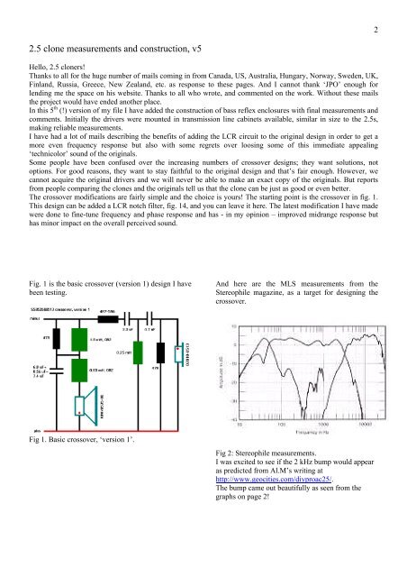
Fig. 1 is the basic crossover (version 1) design I have<br />
been testing.<br />
Fig 1. Basic crossover, ‘version 1’.<br />
And here are the MLS measurements from the<br />
Stereophile magazine, as a target for designing the<br />
crossover.<br />
Fig 2: Stereophile measurements.<br />
I was excited to see if the 2 kHz bump would appear<br />
as predicted from Al.M’s writing at<br />
http://www.geocities.com/diyproac25/.<br />
<strong>The</strong> bump came out beautifully as seen from the<br />
graphs on page 2!<br />
2