

Operating Instructions for Digital Mass Flow Meter and Controller Model: DMS
Operating Instructions for Digital Mass Flow Meter and Controller Model: DMS
Operating Instructions for Digital Mass Flow Meter and Controller Model: DMS

You also want an ePaper? Increase the reach of your titles
YUMPU automatically turns print PDFs into web optimized ePapers that Google loves.
Kobold Messring GmbH Chapter 1 Introduction<br />
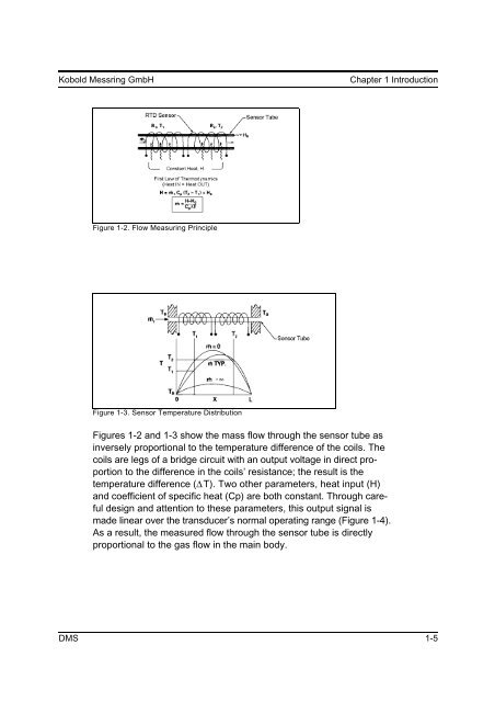
Figure 1-2. <strong>Flow</strong> Measuring Principle<br />
Figure 1-3. Sensor Temperature Distribution<br />
Figures 1-2 <strong>and</strong> 1-3 show the mass flow through the sensor tube as<br />
inversely proportional to the temperature difference of the coils. The<br />
coils are legs of a bridge circuit with an output voltage in direct proportion<br />
to the difference in the coils’ resistance; the result is the<br />
temperature difference ( ΔT). Two other parameters, heat input (H)<br />
<strong>and</strong> coefficient of specific heat (Cp) are both constant. Through careful<br />
design <strong>and</strong> attention to these parameters, this output signal is<br />
made linear over the transducer’s normal operating range (Figure 1-4).<br />
As a result, the measured flow through the sensor tube is directly<br />
proportional to the gas flow in the main body.<br />
<strong>DMS</strong> 1-5