

Xilinx XAPP551 Viterbi Decoder Block Decoding - Trellis ...
Xilinx XAPP551 Viterbi Decoder Block Decoding - Trellis ...
Xilinx XAPP551 Viterbi Decoder Block Decoding - Trellis ...

Create successful ePaper yourself
Turn your PDF publications into a flip-book with our unique Google optimized e-Paper software.
<strong>XAPP551</strong> (v2.0) July 30, 2010<br />
Summary Many digital communication standards employ convolution coding as a means of forward error<br />
correction (FEC). Data encoded in this way generally is decoded with a <strong>Viterbi</strong> decoder, which<br />
operates by constructing a trellis of state probabilities and branch metrics. The transmitted data<br />
is often terminated with a number of zeros to force the encoder back to the zero state. This<br />
allows the decoder to start decoding from a known state, however, extra symbols have to be<br />
transmitted over the channel.<br />
Another termination technique is to ensure the trellis start and end states are identical. This<br />
technique is referred to as tail biting and has the advantage of not requiring any extra symbols<br />
to be transmitted. Tail biting is used in several popular communications standards, such as the<br />
IEEE Standard for Local and Metropolitan Area Networks - Part 16 (IEEE 802.16e) and the<br />
3GPP Long Term Evolution (LTE) standard. This application note gives some background on<br />
the different termination techniques used in these standards, explains how to implement them<br />
using the <strong>Xilinx</strong>® <strong>Viterbi</strong> decoder LogiCORE module (version 6.2 or later), and includes a<br />
number of simulation reference designs to illustrate operation of the <strong>Viterbi</strong> decoder.<br />
<strong>Viterbi</strong><br />
<strong>Decoding</strong><br />
A description of the general <strong>Viterbi</strong> decoding algorithm is beyond the scope of this document.<br />
Refer to the Internet for available tutorial notes. The important concept to understand is that a<br />
trellis is constructed by computing the cost of being in each possible convolution encoder state<br />
at every symbol period. The data bit (0 or 1) most likely to have caused entry to each state is<br />
stored in a table. For example, if the encoder has a six register delay line (that is, constraint<br />
length 7), 2 6 bits are stored for each cycle. After a number of clock cycles, defined by the<br />
traceback length, the decoder traces back through the trellis, outputting the data bits for the<br />
most likely survivor path. This operation is referred to as traceback. Then these bits are passed<br />
through a last in, first out (LIFO) structure, so they are output in the order originally received.<br />
Usually the traceback length is set to be greater than six times the constraint length or greater<br />
than 12 times if the data is punctured.<br />
X-Ref Target - Figure 1<br />
Application Note: All Virtex and Spartan® FPGA Families<br />
<strong>Viterbi</strong> <strong>Decoder</strong> <strong>Block</strong> <strong>Decoding</strong> - <strong>Trellis</strong><br />
Termination and Tail Biting<br />
Author: Michael Francis<br />
Receive TB symbols Receive TB symbols<br />
TB <strong>Block</strong> 0 TB <strong>Block</strong> 1<br />
Traceback for TB <strong>Block</strong> 0<br />
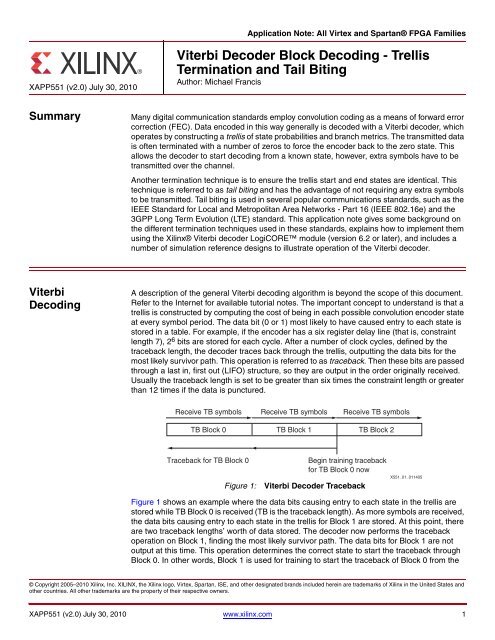
Figure 1: <strong>Viterbi</strong> <strong>Decoder</strong> Traceback<br />
Receive TB symbols<br />
TB <strong>Block</strong> 2<br />
Begin training traceback<br />
for TB <strong>Block</strong> 0 now<br />
X551_01_011405<br />
Figure 1 shows an example where the data bits causing entry to each state in the trellis are<br />
stored while TB <strong>Block</strong> 0 is received (TB is the traceback length). As more symbols are received,<br />
the data bits causing entry to each state in the trellis for <strong>Block</strong> 1 are stored. At this point, there<br />
are two traceback lengths’ worth of data stored. The decoder now performs the traceback<br />
operation on <strong>Block</strong> 1, finding the most likely survivor path. The data bits for <strong>Block</strong> 1 are not<br />
output at this time. This operation determines the correct state to start the traceback through<br />
<strong>Block</strong> 0. In other words, <strong>Block</strong> 1 is used for training to start the traceback of <strong>Block</strong> 0 from the<br />
© Copyright 2005–2010 <strong>Xilinx</strong>, Inc. XILINX, the <strong>Xilinx</strong> logo, Virtex, Spartan, ISE, and other designated brands included herein are trademarks of <strong>Xilinx</strong> in the United States and<br />
other countries. All other trademarks are the property of their respective owners.<br />
<strong>XAPP551</strong> (v2.0) July 30, 2010 www.xilinx.com 1
<strong>Viterbi</strong> <strong>Block</strong> <strong>Decoding</strong><br />
<strong>Viterbi</strong> <strong>Block</strong><br />
<strong>Decoding</strong><br />
correct state. In reality, the upper and lower arrows in Figure 1 are skewed in time. The<br />
traceback for a block occurs some time after the last symbol in the block is sampled. The arrows<br />
are positioned to show on which data the operation is acting. The blocks are sometimes<br />
referred to as windows, and the technique of processing one window at a time is referred to as<br />
the sliding window technique. In the same way, <strong>Block</strong> 2 is used as a training sequence to start<br />
the traceback of <strong>Block</strong> 1 from the correct state.<br />
Convolution codes are not strictly block codes. The decoder operates on a continuous stream<br />
of incoming encoded data, splitting it into traceback lengths for processing. However, it is<br />
convenient to split the data into packets and regard each packet as a self-contained,<br />
independent block. Each packet can contain many traceback lengths of data. Generally, the<br />
encoder is forced to a known starting state and then forced to a known ending state after the<br />
last data bit is shifted in. The most frequently used methods to terminate the trellis in a <strong>Viterbi</strong><br />
decoder are:<br />
<strong>Trellis</strong> truncation<br />
<strong>Trellis</strong> termination<br />
Tail biting<br />
<strong>Trellis</strong> Truncation<br />
<strong>Trellis</strong> truncation is the simplest of all the methods (see Figure 2). The encoder is reset to zero<br />
at the beginning of each packet. Then the data is shifted in. Nothing is done to force the<br />
encoder into a special termination state.<br />
This method has these advantages:<br />
It is simple to implement.<br />
The code rate is not affected, that is, the ratio of original data bits to transmitted bits<br />
remains the same. If the encoder code rate is R and N bits are input, then a total of N/R<br />
bits are transmitted.<br />
This method has these disadvantages:<br />
The bit error rate (BER) performance of the code is degraded because the decoder does<br />
not know from which state to start the last traceback.<br />
There is no data to use as a training sequence to find the correct state. The distance<br />
properties of the convolution code are lost at the end of the packet.<br />
<strong>XAPP551</strong> (v2.0) July 30, 2010 www.xilinx.com 2
<strong>Viterbi</strong> <strong>Block</strong> <strong>Decoding</strong><br />
X-Ref Target - Figure 2<br />
DATA_IN d 0<br />
DATA_IN<br />
Input packet<br />
first bit<br />
Figure 2: Convolutional Encoding for <strong>Trellis</strong> Truncation Termination<br />
<strong>Trellis</strong> Termination (Tail Bits)<br />
Input packet<br />
last bit<br />
d 0 d 1 d 2 d N–7 d N–6 d N–5 d N–4 d N–3 d N–2 d N–1<br />
Input packet (N bits)<br />
Encoder state during transmission<br />
of first output symbol<br />
<strong>Trellis</strong> termination is the most common technique. The encoder is reset to zero at the beginning<br />
of each packet as in trellis truncation. This operation generally happens automatically, as the<br />
previous packet ends in state 0. After all data bits are shifted into the encoder, another Z zero<br />
bits are shifted in, where Z is the number of register stages in the encoder shift register. This<br />
resets the encoder state back to zero. The final output symbols are generated as the Zth zero<br />
is on the input to the encoder shift register. On the next clock cycle, the encoder enters state 0<br />
and no more symbols are transmitted for this packet.<br />
Figure 3 shows this process for a constraint length 7 example. The encoder is initialized to all<br />
zeros, and the first symbol is formed when DATA_IN = d0. The last symbol of the packet is<br />
formed when dN-1 is in the right-most register and the final zero is on DATA_IN. After one more<br />
shift, the encoder is returned to the all zero state. Note that the DATA_OUT symbols are not<br />
transmitted for this state. The decoder can begin traceback for the packet in the certain<br />
knowledge that state 0 is the correct state from which to start.<br />
In trellis termination, both the start state and end state are known by the decoder. This method<br />
has these advantages:<br />
It is fairly simple to implement.<br />
Unlike simple trellis truncation, the termination does not affect the error correction<br />
properties of the convolution code.<br />
<strong>XAPP551</strong> (v2.0) July 30, 2010 www.xilinx.com 3<br />
+<br />
+<br />
+<br />
DATA_OUT_V(0)<br />
0 0 0 0 0 0<br />
+<br />
DATA_OUT_V(1)<br />
Shift N input bits into encoder and<br />
transmit a total of N output symbols<br />
DATA_OUT_V(0)<br />
d n-1 d n-2 d n-3 d n-4 d n-5 d n-6<br />
DATA_OUT_V(1)<br />
Encoder state after transmission<br />
of last output symbol<br />
X551_03_040810
<strong>Viterbi</strong> <strong>Block</strong> <strong>Decoding</strong><br />
This method has these disadvantages:<br />
Extra bits have to be transmitted, reducing the code rate. If there are N bits in the packet,<br />
(N + Z)/R bits are transmitted, where Z is the number of zeros set by the constraint<br />
length - 1 and R is the encoder code rate.<br />
The extra bits consume additional transmission time and slightly reduce the energy-per-bit<br />
to noise-power-spectral-density ratio (Eb/No) for a given probability of error. Typically, the<br />
overall effect is insignificant except when N is very small.<br />
X-Ref Target - Figure 3<br />
DATA_IN d 0<br />
DATA_IN<br />
Tail Biting<br />
Input packet<br />
first bit<br />
d 0<br />
d 1<br />
d 2<br />
Encoder state during transmission<br />
of first output symbol<br />
+<br />
DATA_OUT_V(1)<br />
Figure 3: Convolution Encoding for <strong>Trellis</strong> Zero Termination<br />
Tail biting attempts to overcome the problem of transmitting extra termination bits experienced<br />
by trellis termination. The tail biting technique has these advantages:<br />
The code rate is not affected. N/R bits are transmitted.<br />
The error correction properties of the convolution code are not affected.<br />
The disadvantages are:<br />
Because training is required to determine the correct start state and initial traceback state,<br />
decoding latency is increased over trellis termination.<br />
Receiver complexity is slightly increased.<br />
Tail biting can be done by:<br />
1. Using the last Z data bits of the packet to initialize the encoder shift register prior to<br />
transmission of the packet (number of bits Z = constraint length - 1). No output symbols are<br />
transmitted during encoder initialization. This means that the encoder start state and end<br />
state for the packet are identical. It also implies that the entire packet must be available at<br />
<strong>XAPP551</strong> (v2.0) July 30, 2010 www.xilinx.com 4<br />
+<br />
+<br />
+<br />
d N–1<br />
0<br />
0<br />
DATA_OUT_V(0)<br />
0 0 0 0 0 0<br />
DATA_OUT_V(1)<br />
DATA_OUT_V(0)<br />
0 0 0 0 0 0<br />
0<br />
0<br />
Input packet<br />
last bit<br />
Shift N+6 input bits into encoder and<br />
transmit a total of N+6 output symbols<br />
0<br />
0<br />
Input packet (N+6 bits)<br />
Encoder state after transmission<br />
of last output symbol<br />
X551_02_011405
Implementation<br />
the encoder before the first symbol is transmitted. Figure 4 illustrates this method for an<br />
example with constraint length 7. The encoder is initialized to the last six bits of the packet,<br />
and the first symbol is formed when DATA_IN = d0. The last symbol of the packet is formed<br />
when dN-1 is on DATA_IN. One more shift puts the encoder back into the initial state. The<br />
decoder can then begin traceback of the packet from that state.<br />
2. Initializing the encoder with the first Z data bits of the packet—again not transmitting any<br />
output symbols during this time. The remaining (N - Z) data bits are then encoded and<br />
transmitted, followed by the first Z bits. This has the same effect of causing the start and<br />
end states to be identical. The advantage of this method is that it does not require the entire<br />
packet before encoding starts. However, the bits are out of sequence at the receiver.<br />
X-Ref Target - Figure 4<br />
DATA_IN d0<br />
DATA_IN<br />
Input packet<br />
first bit<br />
Figure 4: Convolution Encoding for Tail Biting Termination<br />
Implementation All termination methods presented can be implemented with the Convolutional Encoder [Ref 1]<br />
and <strong>Viterbi</strong> decoder [Ref 2].<br />
<strong>Trellis</strong> Truncation Encoding<br />
Input packet<br />
last bit<br />
d 0 d 1 d 2 d N–7 d N–6 d N–5 d N–4 d N–3 d N–2 d N–1<br />
Input packet (N bits)<br />
Encoder state during transmission<br />
of first output symbol<br />
Convolutional encoding can be implemented using the Convolutional Encoder (version 6.2 or<br />
later). However, because the encoder is relatively simple, another option is to write RTL code<br />
for the encoder. In the example shown in Figure 5, a 270-bit packet is input into the<br />
convolutional encoder, resulting in 270 symbols. Each symbol is 2 bits for a 1/2 code rate.<br />
<strong>XAPP551</strong> (v2.0) July 30, 2010 www.xilinx.com 5<br />
+<br />
+<br />
+<br />
DATA_OUT_V(0)<br />
d N-1 d N-2 d N-3 d N-4 d N-5 d N-6<br />
+<br />
DATA_OUT_V(1)<br />
Shift N input bits into encoder and<br />
transmit a total of N output symbols<br />
DATA_OUT_V(0)<br />
d N-1 d N-2 d N-3 d N-4 d N-5 d N-6<br />
DATA_OUT_V(1)<br />
Encoder state after transmission<br />
of last output symbol<br />
X551_20_111109
Implementation<br />
X-Ref Target - Figure 5<br />
<strong>Trellis</strong> Termination Encoding<br />
Convolutional encoding can be implemented using either the Convolutional Encoder IP, or<br />
inferred from RTL code. In the example shown in Figure 6, the traceback length is 54 for a<br />
constraint length equal to 9. The packet length is 108 bits, and 8 zeros are appended to the<br />
original packet (constraint length – 1). In Figure 6, the code rate is 1/3, and the number of zeros<br />
appended is 8.<br />
X-Ref Target - Figure 6<br />
Input to Convolutional Encoder 0<br />
269<br />
Output from Convolutional Encoder<br />
The output from the encoder consumes a total of 108 + 8 cycles. This method can be used with<br />
any length packet. A number of zeros (constraint length - 1) still needs to be added, even if the<br />
packet length is less than the traceback length.<br />
Tail Biting Encoding<br />
Input Packet 270 bits<br />
Figure 5: Convolutional Encoding with <strong>Trellis</strong> Truncation<br />
Input To Convolutional Encoder<br />
Output From Convolutional Encoder<br />
Data_out_v(0)<br />
Data_out_v(1)<br />
Data_out_v(0)<br />
Data_out_v(1)<br />
Data_out_v(2)<br />
Figure 6: Convolutional Encoding with <strong>Trellis</strong> Termination<br />
In an example where the constraint length is 7 and the packet length is 270 bits, a circular buffer<br />
stores the packet being transmitted. The last Z bits of the packet are loaded first, followed by the<br />
whole packet. However, the first Z bits are ignored and are not required for transmitting. Thus,<br />
the enable for the encoded data is 270 cycles. In the example shown in Figure 7, the circular<br />
buffer can be implemented using block RAM. As outlined in <strong>Trellis</strong> Termination Encoding,<br />
another approach is to add the first Z bits of the packet prior to encoding.<br />
<strong>XAPP551</strong> (v2.0) July 30, 2010 www.xilinx.com 6<br />
0<br />
269<br />
0 269<br />
Full block encoded and<br />
passed to channel and<br />
then decoded.<br />
X551_14_040810<br />
Input Packet 108 + 8 bits<br />
0 107 00000000<br />
0<br />
107 + 8<br />
0 107 + 8<br />
0 107 + 8<br />
Full block encoded consisting<br />
of 108 symbols + 8, the original<br />
packet and appended zeros<br />
which are passed to channel and<br />
then decoded.<br />
X551_15_040810
Implementation<br />
X-Ref Target - Figure 7<br />
Channel Model<br />
Input To Buffer<br />
Output From Buffer and Input<br />
To Convolutional Encoder<br />
Output From Convolutional Encoder<br />
Figure 7: Convolutional Encoding with Tail Bits<br />
A noisy channel model can be implemented using the Additive White Gaussian Noise (AWGN)<br />
core. See Additive White Gaussian Noise (AWGN) Core v1.0 [Ref 3] for details on testing the<br />
encoder/decoder combination.<br />
<strong>Trellis</strong> Truncation <strong>Decoding</strong> Implementation<br />
Input Packet 270 bits<br />
The <strong>Viterbi</strong> decoder decodes in the normal way, using a sliding window, as shown in Figure 1,<br />
page 1. The trellis construction should start from state 0. The decoder can be forced to give<br />
state 0 the lowest cost at the start of trellis construction (see <strong>Trellis</strong> Termination <strong>Decoder</strong><br />
Implementation, page 9 for details).<br />
Dummy data or data for the next packet is clocked in after the end of the packet to provide a<br />
training sequence for the last block. This training sequence causes the traceback for the last<br />
block to start in a state that might not be the correct state.<br />
One alternative is to not bother with a training sequence for the last block and start the<br />
traceback immediately from the state with the lowest cost. The core can be configured in this<br />
way by selecting Direct Traceback in the core GUI. Select the Best State option to ensure the<br />
traceback begins from the lowest cost state. This option gives the best chance for correct<br />
decoding, however, the results are not as good as when a full training sequence is available. If<br />
traceback is started from the wrong state, some BER degradation occurs at the end of a packet.<br />
Note that the Best State decoding logic increases the core size.<br />
When using the Direct Traceback technique (see Figure 8), the TB_BLOCK input is used to<br />
signal the position of the final TB block of data within a packet. This block is traced back without<br />
a prior training sequence to determine the traceback start state. Traceback of the final TB block<br />
begins immediately after TB_BLOCK is deasserted.<br />
<strong>XAPP551</strong> (v2.0) July 30, 2010 www.xilinx.com 7<br />
0<br />
Tail Bits Added to Packet Prior to<br />
Encoding<br />
264 269<br />
Data_out_v(0)<br />
Data_out_v(1)<br />
0<br />
269<br />
269<br />
0 269<br />
0 269<br />
Full block encoded and last<br />
270 encoded symbols passed<br />
to channel and then decoded.<br />
X551_16_040810
Implementation<br />
X-Ref Target - Figure 8<br />
CLK<br />
PACKET_START<br />
TB_BLOCK<br />
DATA_IN0<br />
DATA_IN1<br />
DATA_OUT_REVERSE<br />
REVERSE_RDY<br />
DATA_OUT_DIRECT<br />
DIRECT_RDY<br />
PACKET_START_O<br />
TB_BLOCK_O<br />
DATA_OUT<br />
T1<br />
Output Latency (see note below figure)<br />
Figure 8: Packet Handling<br />
X551_04_040810<br />
Note relevant to Figure 8:<br />
1. Output latency is shown as two clock cycles for clarity. Actual latency = (8 + output rate)<br />
clock cycles.<br />
In this example, PACKET_START is used to signal the start of the packet. PACKET_START is<br />
used to force the trellis construction to start from a state other than the one the previous block<br />
ended in, as is the case with trellis truncation. See <strong>Trellis</strong> Termination <strong>Decoder</strong> Implementation,<br />
page 9 for more details on PACKET_START.<br />
TB_BLOCK can be asserted at any time. The T1 delay in Figure 8 can be any number of clock<br />
cycles and does not have to be an integer number of traceback lengths. The T1 delay is 0 clock<br />
cycles when there is only one traceback block in the packet. Typically the TB_BLOCK pulse has<br />
a duration of the number of remaining clock cycles when the packet length is divided by the<br />
traceback length. If this remainder is zero, then TB_BLOCK should be the same number of<br />
cycles as the traceback length. The TB_BLOCK pulse can be any duration, within the limits<br />
defined in the <strong>Viterbi</strong> decoder data sheet [Ref 2]. It does not matter if the pulse is less than the<br />
normally required traceback length, because a training sequence is not used to define the start<br />
state of the traceback in this case. TB_BLOCK is used in the same way with trellis termination<br />
and tail biting.<br />
The decoder continues to output decoded data with the normal latency on DATA_OUT. If Direct<br />
Traceback is enabled, the decoder also outputs the data for the last block of the packet on<br />
DATA_OUT_REVERSE. This last block of data is output a small number of clock cycles after<br />
TB_BLOCK is deasserted, and provides data with the lowest possible latency. This is useful if<br />
there is only a single block in a packet because DATA_OUT can be ignored and output data can<br />
be taken from DATA_OUT_REVERSE or DATA_OUT_DIRECT.<br />
Overall latency can be reduced using DATA_OUT_REVERSE even if there are several blocks in<br />
a packet. In this case, DATA_OUT_REVERSE can be buffered in the appropriate locations of a<br />
dual-port RAM while the data for the earlier blocks (on DATA_OUT) is being written to the same<br />
RAM. This means that all decoding has completed as soon as the last symbol for the second<br />
last block on DATA_OUT is written to the RAM. Thus the overall latency can be reduced by TB<br />
cycles.<br />
Because data on DATA_OUT_REVERSE is not passed through the LIFO, it comes out in<br />
reverse order. It is immediately followed by the correctly ordered data on DATA_OUT_DIRECT.<br />
In some applications, it might not matter that the data comes out in reverse and<br />
DATA_OUT_REVERSE can be used to give extremely low latency. The data for the final block<br />
still comes out on DATA_OUT after the normal latency, indicated by TB_BLOCK_O. This data is<br />
identical to the final block data output earlier on DATA_OUT_DIRECT. If latency of the final<br />
<strong>XAPP551</strong> (v2.0) July 30, 2010 www.xilinx.com 8<br />
T1
Implementation<br />
block is not an issue, then it is simplest to always read the decoded data from the DATA_OUT<br />
port and ignore DATA_OUT_REVERSE and DATA_OUT_DIRECT.<br />
<strong>Trellis</strong> Termination <strong>Decoder</strong> Implementation<br />
The packet starts and finishes in state 0. It is desirable to force the decoder to begin the trellis<br />
construction from state 0. Nothing special needs to be done if the previous packet received by<br />
the decoder left state 0 as the most likely state. However, this cannot be guaranteed. Figure 9<br />
shows the BER degradation that occurs when the trellis construction relies on the previous<br />
packet ending in state 0 versus forcing the new packet to start from state 0. This constraint<br />
length 7 example has 32-symbol packets and uses Direct Traceback. The degradation at lower<br />
signal-to-noise ratios (SNRs) is approximately 0.5 dB.<br />
X-Ref Target - Figure 9<br />
BER<br />
10 0<br />
10 -1<br />
10 -2<br />
10 -3<br />
10 -4<br />
10 -5<br />
10 -6<br />
10<br />
0 0.5 1 1.5 2 2.5 3 3.5 4 4.5 5 5.5<br />
-7<br />
Eb/No (dB)<br />
Figure 9: Effect of Incorrect <strong>Trellis</strong> Construction in <strong>Trellis</strong> Termination<br />
<strong>Trellis</strong> Construction<br />
CL7 packet start<br />
CL7 no packet start<br />
BER vs Eb/No<br />
X551_08_011405<br />
The decoder can be forced to begin trellis construction from state 0 in one of two ways:<br />
1. Feed in a number of strong zeros prior to the first real data in the packet. A minimum of Z<br />
zero symbols needs to be sampled to force state 0 to have the lowest cost in the decoder<br />
as illustrated in Figure 10. It does not matter where the decoder is in a traceback block<br />
when the zeros are fed in. The zeros between the packets still force the decoder to the<br />
correct state prior to the start of the real packet data. When these zeros are sampled, the<br />
<strong>XAPP551</strong> (v2.0) July 30, 2010 www.xilinx.com 9
Implementation<br />
core’s BLOCK_IN input can be asserted. BLOCK_OUT then goes to a logic High when the<br />
data corresponding to the input zeros is output. This signal can be used as a flag to ignore<br />
the output data. BLOCK_OUT is simply BLOCK_IN delayed by the decoding latency.<br />
It is not necessary to insert zeros prior to the first packet after a reset as construction of the<br />
first trellis always begins from state 0.<br />
One advantage of this method is that it also takes care of forcing the traceback to state 0 at<br />
the end of a packet. However, there are other ways of doing this task, as described in<br />
Traceback Start.<br />
2. Use the PACKET_START input to force the trellis construction to start at state 0 or any<br />
other state as defined by the PS_STATE input. This input forces the cost for the start state<br />
to be very low and the cost of all the other states to be very high. The advantage of this<br />
method is that it does not waste any clock cycles while dummy zeros are sampled, as in<br />
Method 1. It also avoids the awkward timing and control logic that might be required to<br />
insert dummy zeros. Refer to Figure 8, page 8 for the PACKET_START timing.<br />
X-Ref Target - Figure 10<br />
Construct<br />
trellis<br />
Traceback<br />
and<br />
output data<br />
Figure 10: Forcing <strong>Trellis</strong> Construction Start State to Zero by Zero Insertion<br />
As mentioned at the beginning of this section, it is possible to decode normally without forcing<br />
state 0 to have the lowest cost at the start of a packet. This might cause a BER degradation due<br />
to the reduced likelihood of correcting an error at the start of a packet. The degradation is<br />
noticeable if the channel is noisy when the tail bits for the previous packet are received and<br />
contain errors. Then it is likely that state 0 does not have a significantly lower cost than the other<br />
states as trellis construction for the next packet begins.<br />
Traceback Start<br />
Packet 0 Z Packet 1 Z Packet 2<br />
Z<br />
X551_06_021405<br />
Having taken care of the zero forcing at the start of trellis construction, the user must ensure<br />
that the traceback begins at state 0. The decoder begins traceback from the state with the<br />
lowest cost at the end of the training sequence traceback. If this state can be guaranteed to be<br />
zero, then nothing needs to be done. This will be the case when the next packet begins from<br />
state 0 and is decoded without error, because the first traceback block of the next packet forms<br />
the training sequence for the last traceback block of the current packet. For example, if the last<br />
block of Packet 0 in Figure 10 is being decoded, the first block of Packet 1 is used as the<br />
training sequence. If the traceback through this first block ends in state 0, then the starting state<br />
for the traceback through the last block of Packet 0 will be state 0. Typically this sequence<br />
cannot be guaranteed and the traceback must be forced to start from state 0.<br />
Figure 11 shows the BER degradation that occurs when the traceback relies on the next packet<br />
trellis starting in state 0 versus forcing the traceback to start from state 0. This constraint length<br />
7 example has 96-symbol packets. The degradation at lower SNRs is approximately 0.25 dB.<br />
<strong>XAPP551</strong> (v2.0) July 30, 2010 www.xilinx.com 10
Implementation<br />
X-Ref Target - Figure 11<br />
BER<br />
10 0<br />
10 -1<br />
10 -2<br />
10 -3<br />
10 -4<br />
BER vs Eb/No<br />
Traceback from forced zero<br />
Traceback not forced<br />
10<br />
0 0.5 1 1.5 2 2.5 3 3.5 4 4.5<br />
-5<br />
Eb/No (dB)<br />
X551_07_011805<br />
Figure 11: Effect of Incorrect Traceback Start State in <strong>Trellis</strong> Termination<br />
The traceback of a packet can be forced to start from state 0 in one of two ways:<br />
1. Strong zeros can be inserted between packets in exactly the same way as in the trellis<br />
construction method described in Method 1 on page 9. Again, as long as Z or more zeros<br />
are inserted, traceback can be guaranteed to begin from state 0. As shown in Figure 10,<br />
the zeros do not have to align with the start of the traceback block. All that matters is that<br />
they immediately follow a packet.<br />
This technique assumes that the dummy zeros are immediately followed by the next<br />
packet. If this is the last packet and there is no more data, more dummy input symbols (any<br />
value) should be sampled to flush out the decoder traceback pipeline.<br />
2. Direct Traceback from state 0 can be used for the last block in the packet.<br />
If latency is important, then the processing delay on the last block can be reduced by<br />
selecting this feature. This does away with the training sequence for the last block and<br />
forces the traceback to begin from state 0, saving traceback length clock cycles.<br />
This timing is described in <strong>Trellis</strong> Truncation <strong>Decoding</strong> Implementation, page 7 and is<br />
shown in Figure 8, page 8. The Direct Traceback is identical in this case, with the exception<br />
that we are tracing back from state 0 rather than the Best State.<br />
<strong>XAPP551</strong> (v2.0) July 30, 2010 www.xilinx.com 11
Implementation<br />
X-Ref Target - Figure 12<br />
CLK<br />
PACKET_START<br />
TB_BLOCK<br />
DATA_IN0<br />
DATA_IN1<br />
REVERSE_RDY<br />
DATA_OUT_REVERSE<br />
DIRECT_RDY<br />
For punctured data, the best possible BER results are obtained if the training sequences for<br />
all the other blocks in the packet are started from the Best State. See the <strong>Viterbi</strong> decoder<br />
data sheet [Ref 2] for more details on when to use the Best State logic. It is possible to<br />
trace back from the best state for these blocks while still tracing back from state 0 for the<br />
last block.<br />
There is no BER degradation with Direct Traceback compared to using a training<br />
sequence, because we know for certain that the traceback starts from state 0.<br />
It is also possible to perform Direct Traceback from a non-zero, user-defined state. In this<br />
case, the state value is sampled on the TB_STATE input at the same time as the last data<br />
symbol of the last TB block is sampled.<br />
Figure 12 shows an example with a single small packet, as can be found in the IEEE 802.11a<br />
standard. In this example, the packet contains only a single traceback length, and the<br />
PACKET_START signal is used to force the trellis construction to begin from state 0. As<br />
mentioned above, this can also be achieved by padding with strong zeros prior to the packet.<br />
While TB_BLOCK is High, 24 symbols are sampled. When TB_BLOCK is deasserted, the<br />
decoder begins traceback from state 0 and outputs the packet data in reverse order on<br />
DATA_OUT_REVERSE. This standard requires that the 24-bit header packet is decoded as<br />
quickly as possible. Using DATA_OUT_REVERSE is the fastest way to meet this requirement.<br />
Data follows in non-reversed order on DATA_OUT_DIRECT and DATA_OUT, as described in<br />
the example in Figure 8, page 8.<br />
24 Samples (Rising Clock Edges) Output Latency 24 Output Bits<br />
Figure 12: <strong>Trellis</strong> Termination with a Single Small Packet<br />
Tail Biting <strong>Decoder</strong> Implementation<br />
X551_08_111909<br />
The implementation of tail biting can depend upon the length of the traceback length. There are<br />
three possible scenarios:<br />
The packet contains multiple traceback lengths.<br />
The packet contains a single traceback length.<br />
The packet is less than the traceback length.<br />
In most tail biting applications, the encoder state is initialized to the last Z bits of the data packet<br />
prior to any transmission. Thus the encoder has the same starting and ending states for a<br />
packet. For optimal decoding, the decoder needs to start the trellis construction from this state.<br />
If not done, some BER degradation occurs due to the reduced likelihood of correcting an error<br />
at the start of a packet. The IEEE 802.16d standard uses this form of tail biting. In the LTE<br />
Uplink Channel <strong>Decoder</strong> [Ref 4], some of the tail biting techniques discussed are implemented<br />
for the Physical Downlink Control Channel.<br />
<strong>XAPP551</strong> (v2.0) July 30, 2010 www.xilinx.com 12
Implementation<br />
Packet Contains Multiple Traceback Lengths<br />
This section describes three techniques for decoding packets that contain multiple traceback<br />
lengths: decoding using the first and second traceback blocks, decoding using the last<br />
traceback block first, and decoding for tail biting using the first traceback block first.<br />
<strong>Decoding</strong> Using First and Second Traceback <strong>Block</strong>s<br />
If there are several traceback lengths within a packet, one technique is to decode the first TB<br />
block at the end of the packet. Assuming the packet terminates in the correct state, then the<br />
trellis construction for TB block 0 begins in the correct start state, as illustrated in Figure 13.<br />
This example assumes a packet contains (N + 1) traceback lengths.<br />
X-Ref Target - Figure 13<br />
Construct trellis<br />
TB <strong>Block</strong> 0 TB <strong>Block</strong> 1 - - - - - - - - TB <strong>Block</strong> N TB <strong>Block</strong> 0 TB <strong>Block</strong> 1<br />
Ignore<br />
output data<br />
for <strong>Block</strong> 0<br />
at this time<br />
Received packet<br />
Traceback<br />
and output<br />
data<br />
for <strong>Block</strong> 1<br />
now<br />
Traceback<br />
X551_09_021405<br />
Figure 13: <strong>Decoding</strong> for Tail Bits Using First and Second Traceback <strong>Block</strong>s<br />
TB <strong>Block</strong> 0 is used at the start of the packet only to ensure the trellis construction for TB <strong>Block</strong><br />
1 starts from the correct state. Ignore the output data for TB <strong>Block</strong> 0 at this time because it<br />
might be incorrect due to not knowing from which state to begin the trellis construction. There<br />
is no point using the PACKET_START input. If we did know from which state to begin trellis<br />
construction, we would use PACKET_START, input the state on PS_STATE, and use the data<br />
output for TB <strong>Block</strong> 0 at this time without re-inserting TB <strong>Block</strong> 0 at the end of the packet. The<br />
advantages are:<br />
The re-insertion of <strong>Block</strong> 0 at the end also provides the correct training sequence to start<br />
the traceback of <strong>Block</strong> N from the correct state.<br />
This method clearly adds extra decoding latency for <strong>Block</strong> 0.<br />
The blocks other than the start and end blocks are decoded normally. The end state of one<br />
block automatically provides the start state for the next.<br />
The disadvantages are:<br />
This method adds extra decoding latency (determined by the packet length) for <strong>Block</strong> 0.<br />
The end state of one block automatically provides the start state for the next. Thus, some<br />
buffering is required.<br />
<strong>Decoding</strong> Using Last Traceback <strong>Block</strong> First<br />
Output data<br />
for <strong>Block</strong> 0<br />
now. Also<br />
training for<br />
<strong>Block</strong> N<br />
Training for<br />
<strong>Block</strong> 0.<br />
Ignore<br />
output data<br />
for <strong>Block</strong> 1<br />
Another technique is to input TB <strong>Block</strong> N first, ignoring the output data (see Figure 14). This<br />
technique gives the correct start state for the trellis construction of TB <strong>Block</strong> 0. This block is<br />
followed by blocks 0 to N. TB <strong>Block</strong> 0 is input again at the end to provide a training sequence for<br />
decoding TB <strong>Block</strong> N. The advantages of this technique are:<br />
All the data is output from the decoder in the correct order.<br />
There is no delay for the first traceback block.<br />
The disadvantage of this technique is:<br />
The entire packet must be received before decoding can begin.<br />
<strong>XAPP551</strong> (v2.0) July 30, 2010 www.xilinx.com 13
Implementation<br />
X-Ref Target - Figure 15<br />
X-Ref Target - Figure 16<br />
CLK<br />
TB_BLOCK<br />
TB_STATE<br />
DATA_IN0<br />
DATA_IN1<br />
DATA_OUT<br />
TB_BLOCK<br />
Construct trellis<br />
Input TB <strong>Block</strong> 0<br />
TB <strong>Block</strong> 0<br />
Ignore<br />
output data<br />
for <strong>Block</strong> 0<br />
at this time<br />
X-Ref Target - Figure 14<br />
TB <strong>Block</strong> N<br />
Ignore Output Data<br />
for <strong>Block</strong> N Now<br />
TB <strong>Block</strong> 0<br />
Traceback and<br />
Output for <strong>Block</strong><br />
0 Now<br />
Received Packet<br />
• • • • • • • •<br />
TB <strong>Block</strong> N<br />
Traceback and<br />
Output for <strong>Block</strong><br />
0 Now<br />
Figure 14: <strong>Decoding</strong> for Tail Biting Using Last Traceback <strong>Block</strong>s<br />
<strong>Decoding</strong> for Tail Biting Using First Traceback <strong>Block</strong> First<br />
TB <strong>Block</strong> 0<br />
Training Data for<br />
<strong>Block</strong> N<br />
Ignore Output Data<br />
for <strong>Block</strong> 0<br />
X551_17_100309<br />
The core’s Direct Traceback feature can be used to perform the decoding without the need to<br />
re-insert TB <strong>Block</strong> 1 at the end, as in Figure 13. This technique is shown in Figure 15.<br />
Received packet<br />
TB <strong>Block</strong> 1<br />
Traceback and<br />
output data<br />
for <strong>Block</strong> 1<br />
now<br />
- - - - - - - - TB <strong>Block</strong> N TB <strong>Block</strong> 0<br />
Traceback<br />
Output data<br />
for <strong>Block</strong> 0 now.<br />
Also training for<br />
<strong>Block</strong> N<br />
Figure 15: <strong>Decoding</strong> for Tail Biting using Direct Traceback<br />
First Z bits of TB <strong>Block</strong> 1 are<br />
used as input values on TB_STATE<br />
X551_10_021405<br />
In this case, TB <strong>Block</strong> 0 is still used initially to obtain the correct starting state for the trellis<br />
construction during TB <strong>Block</strong> 1 and the first output data for TB <strong>Block</strong> 0 is ignored. When the<br />
data for TB <strong>Block</strong> 1 appears on DATA_OUT, the first Z bits can be saved in a register, giving the<br />
correct traceback start state to begin the decoding of TB <strong>Block</strong> 0. Thus TB <strong>Block</strong> 1 does not<br />
need to be re-inserted at the end of the packet to determine the start state for the TB <strong>Block</strong> 0<br />
traceback. Simply apply the saved start state on the TB_STATE input at the same time that the<br />
last symbol of TB BLOCK 0 is sampled on DATA_IN (the timing is shown in Figure 16). In this<br />
example, the constraint length is 7 and Z is 6. The first six bits of TB <strong>Block</strong> 1 are decoded as<br />
110000 binary, giving the state the encoder shift register was in immediately after TB <strong>Block</strong> 0<br />
and hence the correct state with which to begin the Direct Traceback of TB <strong>Block</strong> 0. Input a<br />
value of 3 (000011 binary) on TB_STATE at the end of the TB_BLOCK pulse. The traceback of<br />
TB <strong>Block</strong> 0 then begins from the correct state (3) without requiring a training sequence. Not all<br />
clock cycles are shown in Figure 16. In reality, the blocks and latencies are longer than shown.<br />
Input TB <strong>Block</strong> 1<br />
<strong>Decoder</strong> Latency<br />
Input TB <strong>Block</strong>s 2 to N-1<br />
1 1 0 0 0 0<br />
Input TB <strong>Block</strong> N<br />
Figure 16: Timing for Direct Traceback Tail Biting Technique<br />
Re-input TB <strong>Block</strong> 0<br />
Output TB <strong>Block</strong> 0 Output TB <strong>Block</strong> 1 Output remaining TB <strong>Block</strong>s 2 to N<br />
<strong>XAPP551</strong> (v2.0) July 30, 2010 www.xilinx.com 14<br />
3<br />
X551_11_021405
Implementation<br />
This technique relies on being able to decode the first Z bits of TB <strong>Block</strong> 1 before the state value<br />
is required for the TB_STATE input. There might not be sufficient time to perform this operation<br />
if there is only a small number of TB <strong>Block</strong>s in a packet. In this case, the method shown in<br />
Figure 13, page 13 can be used.<br />
Packet Contains Single Traceback Length<br />
If the packet contains only a single traceback length, then the technique is effectively the same<br />
as passing <strong>Block</strong> 0 through the decoder three times: once to ensure the correct start state for<br />
the trellis construction, once to construct the trellis, and once to perform the correct training so<br />
the traceback begins from the correct state (see Figure 17). The Direct Traceback technique<br />
cannot be used in this case, because the traceback start state cannot be obtained to apply to<br />
TB_STATE.<br />
X-Ref Target - Figure 17<br />
Received<br />
packet<br />
Construct trellis<br />
TB <strong>Block</strong> 0<br />
Ignore<br />
output data<br />
for <strong>Block</strong> 0<br />
at this time<br />
TB <strong>Block</strong> 0 TB <strong>Block</strong> 0<br />
Traceback and<br />
output data<br />
for <strong>Block</strong> 0<br />
now<br />
Training for<br />
<strong>Block</strong> 0.<br />
Ignore<br />
output data<br />
Figure 17: Single <strong>Block</strong> Packet<br />
X551_12_021405<br />
<strong>Block</strong> 0 must be passed through three times. If it passes through only twice, BER degradation<br />
is substantial, resulting in almost all packets decoding incorrectly. Figure 18 shows a small<br />
32-symbol, constraint length 3 example. The curves for tail biting, implemented by passing the<br />
block through the decoder three times and a standard continuous stream (non-tail biting)<br />
decoder are almost identical. The curve obtained when the block is only passed through twice<br />
shows considerably worse BER performance. For larger constraint lengths, this performance is<br />
even worse because the likelihood of choosing the correct starting state by chance is reduced.<br />
<strong>XAPP551</strong> (v2.0) July 30, 2010 www.xilinx.com 15
Implementation<br />
X-Ref Target - Figure 18<br />
BER<br />
10 -1<br />
10 -2<br />
10 -3<br />
10 -4<br />
10 -5<br />
10 -6<br />
10 -7<br />
BER vs Eb/No<br />
3 4 5 6 7 8<br />
Eb/No (dB)<br />
9 10 11 12 13<br />
Figure 18: Effect of Incorrect <strong>Trellis</strong> Construction in Tail Biting<br />
Packet Contains Less Than One Traceback Length<br />
CL3 Continuous<br />
CL3 3 <strong>Block</strong>s<br />
CL3 2 <strong>Block</strong>s<br />
X551_13_120304<br />
In this case the packet of data is less than the traceback length. Thus, the decoder does not<br />
have enough data to construct the trellis, start at the correct point in the trellis, and perform the<br />
correct training. Therefore, copies of the packet data are repeated before and after the actual<br />
packet block. The repeated packet data is traceback length to allow construction and training of<br />
the data.<br />
In the example shown in Figure 19, the packet length is 27 bits and the traceback length is<br />
42 bits. Because tail biting is being performed, the last Z bits of the packet are used to initialize<br />
the decoder. A traceback-length block of data is the first input to the <strong>Viterbi</strong> decoder from the<br />
circular buffer. The block consists of the last 15 bits of the packet followed by the 27 packet bits.<br />
The 27-bit block being decoded is then input, indicated by assertion of the BLOCK_IN signal,<br />
followed by another 27-bit block and the first 15 bits of the next block, which is used for<br />
traceback training. The <strong>Viterbi</strong> decoder outputs the 27-bit packet indicated by the RDY signal and<br />
the BLOCK_OUT signal.<br />
<strong>XAPP551</strong> (v2.0) July 30, 2010 www.xilinx.com 16
Recommendations<br />
Refer to Tail Biting Example in the design section.<br />
Recommendations When implementing a termination system, these recommendations should be kept in mind:<br />
Use trellis termination or tail biting methods.<br />
Only use tail biting if it is specified in the standard.<br />
Use direct traceback if latency is important.<br />
Set the soft width of the <strong>Viterbi</strong> decoder to four.<br />
Set the traceback length to 6 times the constraint length for normal data and 12 times for<br />
punctured data.<br />
Reference<br />
Designs<br />
X-Ref Target - Figure 19<br />
Output From <strong>Viterbi</strong><br />
Circular Buffer<br />
and Input to<br />
<strong>Viterbi</strong> <strong>Decoder</strong><br />
42 Symbols of Soft Data 42 Symbols of Soft Data<br />
Cost Training<br />
12 26 0 26 0 26 0 TB <strong>Block</strong> N 26 0 14<br />
Decoded Output<br />
Data From <strong>Viterbi</strong><br />
<strong>Decoder</strong><br />
Figure 19: <strong>Decoding</strong> for Tail Bits for Small Packet Lengths<br />
The reference design files can be downloaded at<br />
https://secure.xilinx.com/webreg/clickthrough.do?cid=146331. Table 1 shows the reference<br />
design checklist for this application note.<br />
Table 1: Reference Design Checklist<br />
General<br />
<strong>XAPP551</strong> (v2.0) July 30, 2010 www.xilinx.com 17<br />
0<br />
<strong>Block</strong> to be<br />
Decoded<br />
26<br />
Traceback<br />
Training<br />
Parameter Description<br />
Target devices (stepping level, ES, production, speed grades) Virtex®-6 FPGAs<br />
Source code provided Y<br />
Source code format VHDL<br />
Design uses IP from CORE Generator software Y<br />
Simulation<br />
Functional simulation performed Y<br />
Timing simulation performed N<br />
Testbench used for functional and timing simulations Y<br />
Testbench format VHDL<br />
Simulator software/version used ModelSim 6.5c<br />
SPICE/IBIS simulations N<br />
Implementation<br />
Synthesis software tools/version used XST 12.1<br />
Implementation software tools/versions used ISE 12.1<br />
Static timing analysis performed Y<br />
X551_18_040810
Reference Designs<br />
Table 1: Reference Design Checklist (Cont’d)<br />
Hardware Verification<br />
Hardware verified N<br />
Hardware platform used for verification NA<br />
The xapp551.zip file associated with this application note contains three termination scheme<br />
examples: tail biting, trellis termination training sequence, and trellis termination direct<br />
traceback. Each example contains an XISE file that can be opened with the <strong>Xilinx</strong> ISE® design<br />
suite (version 11.3 or later), a <strong>Viterbi</strong> decoder implementation, testbench files, and DO scripts<br />
for ModelSim simulations. The example files are not synthesizable, but they illustrate how these<br />
techniques aid the development of hardware solutions.<br />
The examples share a similar format, which is outlined in Table 2, Table 3, and Table 4. Also<br />
provided is a data source, which can be put into packets and sent through a convolutional<br />
encoder. A channel model is used to add noise to the encoded signal before decoding. The<br />
decoded signal is then compared with the delayed version of the data source.<br />
X-Ref Target - Figure 20<br />
Stimulus –<br />
Random Packet<br />
Lengths with<br />
Random Data<br />
Packet<br />
Stimulus<br />
Tail Biting Example<br />
Parameter Description<br />
Convolution<br />
Encoder<br />
Table 2: Description of Files for Tail Biting Example<br />
Convolution<br />
Encoder<br />
Channel with<br />
AWGN<br />
Channel<br />
<strong>Viterbi</strong><br />
<strong>Decoder</strong><br />
<strong>Viterbi</strong><br />
<strong>Decoder</strong><br />
Figure 20: Testbench Configuration<br />
Compare<br />
This example shows tail biting techniques. The example files are described in Table 2.<br />
Directory File Name Description<br />
tail_biting/sim/test<br />
tail_biting/sim/globals<br />
tail_biting/sim/enc<br />
tail_biting/sim/channel<br />
tb.vhd<br />
fifo_wrap.vhd<br />
glb_dpm.vhd<br />
X551_19_100309<br />
This file instantiates the blocks shown in Figure 20, but for<br />
tail biting. It shows how the testbench processes the input<br />
packet through the various buffering, encoding, and<br />
decoding stages.<br />
This file is the wrapper for the FIFO in the<br />
CORE Generator software.<br />
This file is the wrapper for the dual port block RAM in the<br />
CORE Generator software.<br />
global_types_pkg.vhd This file contains global type and constant definitions.<br />
circ_buffer_enc.vhd<br />
conv_enc.vhd<br />
awgn_gen.vhd<br />
This file contains the circular buffer used for reading the six<br />
tail biting bits.<br />
This file contains the convolutional encoder with circular<br />
buffer instantiation. This is a constraint length 7 encoder with<br />
a rate of 1/3.<br />
This file contains the behavioral model for the AWGN<br />
channel.<br />
<strong>XAPP551</strong> (v2.0) July 30, 2010 www.xilinx.com 18
Reference Designs<br />
Table 2: Description of Files for Tail Biting Example (Cont’d)<br />
Directory File Name Description<br />
tail_biting/sim/dec<br />
circ_buffer_dec.vhd<br />
vit_dec.vhd<br />
To run the simulation, the vit.do file is executed. This file compiles the design files, opens a<br />
wave window, and simulates the design. The packet size can be modified by changing these<br />
lines in the tb.vhd file:<br />
constant PACKET_ULIMIT : positive := 100; -- upper limit on packet size<br />
constant PACKET_LLIMIT : positive := 20; -- lower limit on packet size<br />
<strong>Trellis</strong> Termination Training Sequence Example<br />
This file contains the circular buffer, which is used for<br />
generating the training sequence that is wrapped around the<br />
<strong>Viterbi</strong> packet to be decoded.<br />
This file contains the top level of the decoder. It instantiates<br />
the circular buffer and <strong>Viterbi</strong> decoder. It handles block valid<br />
and data flow signals.<br />
tail_biting/ vit.do This file is the simulation script for use with ModelSim.<br />
wave_vit.do<br />
tail_biting.xise<br />
This file is the simulation script for use with ModelSim that<br />
puts the relevant signals in the wave window.<br />
This example illustrates the <strong>Viterbi</strong> decoder used in a trellis termination scheme. To run the<br />
vit.do file in the ISE software project, select simulation and double-click.<br />
The example files are described in Table 3.<br />
Table 3: Description of Files for <strong>Trellis</strong> Termination Training Sequence Example<br />
This file contains the ISE software project. To run the<br />
implementation, open tail_biting.xise with the ISE<br />
tool and run the flow.<br />
Directory File Name Description<br />
training_seq/sim/test<br />
tb.vhd<br />
This file instantiates the blocks shown Figure 20, but for trellis<br />
termination. It shows how the testbench processes the input<br />
packet through the various buffering, encoding, and decoding<br />
stages.<br />
training_seq/sim/globals conversion_pkg.vhd This file is the package file for converting signals.<br />
training_seq/sim/enc<br />
conv_enc.vhd<br />
This file contains the convolutional encoder with circular buffer<br />
instantiation. This is a constraint length 7 encoder with rate 1/2.<br />
training_seq/channel awgn_gen.vhd This file contains the behavioral model for the AWGN channel.<br />
training_seq/ training_seq.do This file is the simulation script for use with ModelSim.<br />
wave_vit.do<br />
training_seq.xise<br />
This file is the simulation script for use with ModelSim that puts<br />
the relevant signals in the wave window.<br />
This file contains the ISE software project. To run the<br />
implementation, open training_seq.xise with the ISE tool<br />
and run the flow.<br />
To run the simulation, open the ISE software project and run the behavioral simulation. This file<br />
compiles the design files, opens a wave window, and simulates the design. The packet size can<br />
be modified by changing these lines in the tb.vhd file.<br />
-- patterned or random input<br />
constant RANDOM_INPUT : boolean := TRUE;<br />
-- limit size of random input packets >= 1<br />
constant PACKET_LIMIT : positive := 40; -- can be set to any value<br />
<strong>XAPP551</strong> (v2.0) July 30, 2010 www.xilinx.com 19
Conclusion<br />
<strong>Trellis</strong> Termination Direct Traceback Example<br />
This example illustrates the trellis termination using direct traceback. The example files are<br />
described in Table 4.<br />
Table 4: Description of Files for <strong>Trellis</strong> Termination Direct Traceback Example<br />
Directory File Name Description<br />
direct_traceback/sim/test<br />
tb.vhd<br />
The simulation is run by opening the ISE software project and running the behavioral<br />
simulation.<br />
Conclusion In the latest communication standards, some control information is required to be sent via<br />
packets. These packets can vary in length. This application note describes how, using trellis<br />
termination and tail biting techniques, these packets can be transmitted and decoded<br />
successfully using the <strong>Xilinx</strong> <strong>Viterbi</strong> decoder.<br />
References These product pages provide additional information and links useful to this application note:<br />
1. Convolutional Encoder<br />
http://www.xilinx.com/products/ipcenter/Convolutional_Encoder.htm<br />
2. <strong>Viterbi</strong> <strong>Decoder</strong><br />
http://www.xilinx.com/products/ipcenter/<strong>Viterbi</strong>_<strong>Decoder</strong>.htm<br />
3. Additive White Gaussian Noise (AWGN) Core<br />
http://www.xilinx.com/products/ipcenter/DO-DI-AWGN.htm<br />
This file instantiates the blocks shown in Figure 20, but<br />
for direct traceback. It shows how the testbench<br />
processes the input packet through the various<br />
buffering, encoding, and decoding stages.<br />
direct_traceback/sim/globals conversion_pkg.vhd This file is the package file for converting signals.<br />
direct_traceback/enc<br />
direct_traceback/sim/channel<br />
conv_enc.vhd<br />
awgn_gen.vhd<br />
This file contains the convolutional encoder with<br />
circular buffer instantiation. This is a constraint length<br />
9 encoder with rate 1/2.<br />
This file contains the behavioral model for the AWGN<br />
channel.<br />
direct_traceback/ direct_traceback.do This file is the simulation script for use with ModelSim.<br />
wave_vit.do<br />
direct_traceback.xise<br />
This file is the simulation script for use with ModelSim<br />
that puts the relevant signals in the wave window.<br />
This file contains the ISE software project. To run the<br />
implementation, open direct_traceback.xise<br />
with the ISE tool and run the flow.<br />
4. 3GPP LTE UL Channel <strong>Decoder</strong><br />
http://www.xilinx.com/products/ipcenter/DO-DI-CHDEC-LTE.htm<br />
<strong>XAPP551</strong> (v2.0) July 30, 2010 www.xilinx.com 20
Revision History<br />
Revision<br />
History<br />
Notice of<br />
Disclaimer<br />
The following table shows the revision history for this document.<br />
Date Version Description of Revisions<br />
02/14/05 1.0 Initial <strong>Xilinx</strong> release.<br />
07/30/10 2.0 Added Figure 2, Figure 5, Figure 6, Figure 7, Figure 14, Figure 19, and<br />
Figure 20.<br />
Added <strong>Trellis</strong> Truncation Encoding, <strong>Trellis</strong> Termination Encoding, Tail<br />
Biting Encoding, Channel Model, Traceback Start, Packet Contains<br />
Multiple Traceback Lengths, Packet Contains Single Traceback Length,<br />
Packet Contains Less Than One Traceback Length, Recommendations,<br />
Reference Designs, and References sections.<br />
Clarified that reference designs are simulation reference designs in<br />
Summary. Updated traceback length setting for data punctures in <strong>Viterbi</strong><br />
<strong>Decoding</strong>. Reorganized text in Tail Biting. Added possible scenarios to<br />
the beginning of Tail Biting <strong>Decoder</strong> Implementation. Added Table 1.<br />
<strong>Xilinx</strong> is disclosing this Application Note to you “AS-IS” with no warranty of any kind. This Application Note<br />
is one possible implementation of this feature, application, or standard, and is subject to change without<br />
further notice from <strong>Xilinx</strong>. You are responsible for obtaining any rights you may require in connection with<br />
your use or implementation of this Application Note. XILINX MAKES NO REPRESENTATIONS OR<br />
WARRANTIES, WHETHER EXPRESS OR IMPLIED, STATUTORY OR OTHERWISE, INCLUDING,<br />
WITHOUT LIMITATION, IMPLIED WARRANTIES OF MERCHANTABILITY, NONINFRINGEMENT, OR<br />
FITNESS FOR A PARTICULAR PURPOSE. IN NO EVENT WILL XILINX BE LIABLE FOR ANY LOSS OF<br />
DATA, LOST PROFITS, OR FOR ANY SPECIAL, INCIDENTAL, CONSEQUENTIAL, OR INDIRECT<br />
DAMAGES ARISING FROM YOUR USE OF THIS APPLICATION NOTE.<br />
<strong>XAPP551</strong> (v2.0) July 30, 2010 www.xilinx.com 21


