Lab 4-2 Multi-Area Integrated IS-IS
Lab 4-2 Multi-Area Integrated IS-IS
Lab 4-2 Multi-Area Integrated IS-IS

Create successful ePaper yourself
Turn your PDF publications into a flip-book with our unique Google optimized e-Paper software.
<strong>Lab</strong> 4-2 <strong>Multi</strong>-<strong>Area</strong> <strong>Integrated</strong> <strong>IS</strong>-<strong>IS</strong><br />
Learning Objectives<br />
• Configure multi-area integrated <strong>IS</strong>-<strong>IS</strong><br />
• Review configuration of <strong>IS</strong>-<strong>IS</strong> Level 1 and Level 2 intermediate systems<br />
• Verify <strong>IS</strong>-<strong>IS</strong> adjacencies and view the <strong>IS</strong>-<strong>IS</strong> database<br />
• Review <strong>IS</strong>-<strong>IS</strong> domain authentication<br />
• Verify intra-area <strong>IS</strong>-<strong>IS</strong> operation<br />
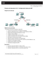
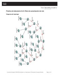
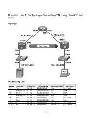
Topology Diagram<br />
Scenario<br />
Previous tests demonstrated that <strong>Integrated</strong> <strong>IS</strong>-<strong>IS</strong> works well with Level 2<br />
routers in the International Travel Agency (ITA) Ethernet core. Management<br />
now wants to establish a point-to-point connection between a new R3 office and<br />
R1. R3 is in a different area from the core, so R2 will now be configured as an<br />
L1 router, R1 as an L1-L2 router, and R3 as an L2 router.<br />
Start with the final configurations for R1 and R2 from the first <strong>IS</strong>-<strong>IS</strong> lab.<br />
1 - 14 CCNP: Building Scalable Internetworks v5.0 - <strong>Lab</strong> 4-2 Copyright © 2006, Cisco Systems, Inc
Step 1: Addressing and Initial Configuration<br />
Load the R1 and R2 configurations from the previous lab. Add to the<br />
configuration of R1, the IP address for interface serial 0/0/1.<br />
R1:<br />
R1(config)# interface serial 0/0/1<br />
R1(config-if)# ip address 10.0.0.2 255.255.255.252<br />
R1(config-if)# no shutdown<br />
R1(config-if)# exit<br />
Do not load the R3 configurations from the previous lab. You should start with<br />
a fresh configuration on R3, so clear and reload the router that is to be used as<br />
R3. Configure the IP address and clock rate on R3’s serial interface. Configure<br />
the hostname, turn off DNS lookup, configure the IP address on the serial<br />
interface, and configure the loopback IP address on R3.<br />
R3:<br />
Router(config)# hostname R3<br />
R3(config)# no ip domain-lookup<br />
R3(config)# interface serial 0/0/0<br />
R3(config-if)# ip address 10.0.0.l 255.255.255.252<br />
R3(config-if)# clockrate 128000<br />
R3(config-if)# no shutdown<br />
R3(config-if)# interface loopback 0<br />
R3(config-if)# ip address 192.168.30.1 255.255.255.0<br />
Use ping to verify connectivity between the directly connected interfaces. R1<br />
should also be able to reach the loopback address of R2 and vice versa.<br />
Step 2: Verify <strong>IS</strong>-<strong>IS</strong> Initial Operation<br />
Recall from <strong>Lab</strong> 4.1 that R1 was configured to be the D<strong>IS</strong> by setting the isis<br />
priority to 100 on the FastEthernet 0/0 interface. R1 and R2 were also<br />
configured to be Level 2-only routers. Verify the configuration by issuing the<br />
show clns neighbors and show isis database commands on either router.<br />
Note: It is recommended to issue a clear isis * command to force <strong>IS</strong>-<strong>IS</strong> to<br />
update its database. An alternative way to force <strong>IS</strong>-<strong>IS</strong> to update its database, is<br />
to save your configurations and reload the routers.<br />
R1# show clns neighbors<br />
System Id Interface SNPA State Holdtime Type Protocol<br />
R2 Fa0/0 0004.9ad2.d0c0 Up 12 L2 <strong>IS</strong>-<strong>IS</strong><br />
R1# show isis database<br />
<strong>IS</strong>-<strong>IS</strong> Level-2 Link State Database:<br />
LSPID LSP Seq Num LSP Checksum LSP Holdtime ATT/P/OL<br />
2 - 14 CCNP: Building Scalable Internetworks v5.0 - <strong>Lab</strong> 4-2 Copyright © 2006, Cisco Systems, Inc
R1.00-00 * 0x00000014 0xBCC5 409 0/0/0<br />
R1.01-00 * 0x00000015 0x1B0D 819 0/0/0<br />
R2.00-00 0x00000016 0x326D 698 0/0/0<br />
Notice that the neighbor Type is still L2. There is only one L2 link-state<br />
database, and R1 is still the D<strong>IS</strong>. LSPID R1.01-00 has a non-zero pseudonode<br />
ID. The LSPID may appear as R1.02-00, depending on the timing of the<br />
configuration of the loopback interface.<br />
Step 3: Configure <strong>IS</strong>-<strong>IS</strong> <strong>Area</strong> 2<br />
Configure <strong>IS</strong>-<strong>IS</strong> on R3, area 2, and on the Serial 0/0/1 interface of R1:<br />
R3:<br />
R3(config)# router isis<br />
R3(config-router)# net 49.0002.3333.3333.3333.00<br />
R3(config-router)# interface serial 0/0/0<br />
R3(config-if)# ip router isis<br />
R3(config-if)# interface loopback 0<br />
R3(config-if)# ip router isis<br />
R1:<br />
R1(config)# interface serial 0/0/1<br />
R1(config-if)# ip router isis<br />
Which <strong>IS</strong>-<strong>IS</strong> level is the link between R1 and R3?<br />
Step 4: Verify <strong>IS</strong>-<strong>IS</strong> <strong>Multi</strong>-<strong>Area</strong> Operation<br />
Verify <strong>IS</strong>-<strong>IS</strong> operation between R1 and R3 by pinging the loopback addresses<br />
on R1 and R2 from R3. The ping should be successful. Issue show commands<br />
on R3 as shown in the following examples.<br />
R3# show clns neighbor<br />
System Id Interface SNPA State Holdtime Type Protocol<br />
R1 Se0/0/0 *HDLC* Up 28 L2 <strong>IS</strong>-<strong>IS</strong><br />
Because serial interfaces do not have a MAC address, the encapsulation type<br />
for the serial link is listed in the SNPA column.<br />
R3# show isis database<br />
<strong>IS</strong>-<strong>IS</strong> Level-1 Link State Database:<br />
LSPID LSP Seq Num LSP Checksum LSP Holdtime ATT/P/OL<br />
R3.00-00 * 0x00000009 0x8FFA 1180 1/0/0<br />
<strong>IS</strong>-<strong>IS</strong> Level-2 Link State Database:<br />
LSPID LSP Seq Num LSP Checksum LSP Holdtime ATT/P/OL<br />
R1.00-00 0x0000001C 0x25EC 1174 0/0/0<br />
R1.01-00 0x00000017 0x170F 965 0/0/0<br />
3 - 14 CCNP: Building Scalable Internetworks v5.0 - <strong>Lab</strong> 4-2 Copyright © 2006, Cisco Systems, Inc
R2.00-00 0x00000018 0x2E6F 794 0/0/0<br />
R3.00-00 * 0x00000008 0x4551 1176 0/0/0<br />
By default, R3 is an L1-L2 router, so it retains a separate link-state database for<br />
each level. R1 is also identified as the D<strong>IS</strong>. R1 and R2 are not listed in the <strong>IS</strong>-<strong>IS</strong><br />
Level 1 link-state database, because both were previously configured as L2only<br />
routers.<br />
R3# show clns interface serial 0/0/0<br />
Serial0/0/0 is up, line protocol is up<br />
Checksums enabled, MTU 1500, Encapsulation HDLC<br />
ERPDUs enabled, min. interval 10 msec.<br />
CLNS fast switching enabled<br />
CLNS SSE switching disabled<br />
DEC compatibility mode OFF for this interface<br />
Next ESH/<strong>IS</strong>H in 26 seconds<br />
Routing Protocol: <strong>IS</strong>-<strong>IS</strong><br />
Circuit Type: level-1-2<br />
Interface number 0x0, local circuit ID 0x100<br />
Neighbor System-ID: R1<br />
Level-1 Metric: 10, Priority: 64, Circuit ID: R3.00<br />
Level-1 IPv6 Metric: 10<br />
Number of active level-1 adjacencies: 0<br />
Level-2 Metric: 10, Priority: 64, Circuit ID: R3.00<br />
Level-2 IPv6 Metric: 10<br />
Number of active level-2 adjacencies: 1<br />
Next <strong>IS</strong>-<strong>IS</strong> Hello in 5 seconds<br />
if state UP<br />
Note that the circuit ID is R3.00.<br />
From R1, ping 192.168.30.1 on R3. The ping should not be successful.<br />
R1# ping 192.168.30.1<br />
Type escape sequence to abort.<br />
Sending 5, 100-byte ICMP Echos to 192.168.30.1, timeout is 2 seconds:<br />
.....<br />
Success rate is 100 percent (5/5), round-trip min/avg/max = 1/2/4 ms<br />
Why do you think the ping was unsuccessful?<br />
Check the IP routing table of R1 and R3:<br />
R1# show ip route<br />
<br />
Gateway of last resort is not set<br />
C 192.168.10.0/24 is directly connected, FastEthernet0/1<br />
172.16.0.0/24 is subnetted, 1 subnets<br />
C 172.16.0.0 is directly connected, FastEthernet0/0<br />
i L2 192.168.20.0/24 [115/20] via 172.16.0.2, FastEthernet0/0<br />
10.0.0.0/30 is subnetted, 1 subnets<br />
4 - 14 CCNP: Building Scalable Internetworks v5.0 - <strong>Lab</strong> 4-2 Copyright © 2006, Cisco Systems, Inc
C 10.0.0.0 is directly connected, Serial0/0/1<br />
R3# show ip route<br />
<br />
Gateway of last resort is not set<br />
C 192.168.30.0/24 is directly connected, Loopback0<br />
i L2 192.168.10.0/24 [115/20] via 10.0.0.2, Serial0/0/0<br />
172.16.0.0/24 is subnetted, 1 subnets<br />
i L2 172.16.0.0 [115/20] via 10.0.0.2, Serial0/0/0<br />
i L2 192.168.20.0/24 [115/30] via 10.0.0.2, Serial0/0/0<br />
10.0.0.0/30 is subnetted, 1 subnets<br />
C 10.0.0.0 is directly connected, Serial0/0/0<br />
Which <strong>IS</strong>-<strong>IS</strong> routes are missing on R1?<br />
All prior checks indicated that <strong>IS</strong>-<strong>IS</strong> was working properly between R1 and R3.<br />
However, there is no entry in the routing table for the 192.168.30.0 network.<br />
The next step will demonstrate why this is the case.<br />
Step 5: Configure <strong>IS</strong>-<strong>IS</strong> Domain Authentication<br />
During Step 3, you may have seen the following output message:<br />
R1#<br />
*Oct 9 23:56:53.275: %CLNS-4-AUTH_FAIL: <strong>IS</strong><strong>IS</strong>: LSP authentication failed<br />
Recall that domain password authentication was configured on both R1 and R2.<br />
If domain authentication is to be retained, R3 also needs to be configured<br />
appropriately, as follows:<br />
R3(config)# router isis<br />
R3(config-router)# domain-password cisco<br />
What is this password used to authenticate?<br />
Now examine the routing table of either R1 or R2. A sample for R1 is shown:<br />
R1# show ip route<br />
<br />
Gateway of last resort is not set<br />
i L2 192.168.30.0/24 [115/20] via 10.0.0.1, Serial0/0/1<br />
C 192.168.10.0/24 is directly connected, FastEthernet0/1<br />
172.16.0.0/24 is subnetted, 1 subnets<br />
C 172.16.0.0 is directly connected, FastEthernet0/0<br />
5 - 14 CCNP: Building Scalable Internetworks v5.0 - <strong>Lab</strong> 4-2 Copyright © 2006, Cisco Systems, Inc
i L2 192.168.20.0/24 [115/20] via 172.16.0.2, FastEthernet0/0<br />
10.0.0.0/30 is subnetted, 1 subnets<br />
C 10.0.0.0 is directly connected, Serial0/0/1<br />
The route to 192.168.30.0 now appears and a ping from R1 or R2 to<br />
192.168.30.1 should be successful.<br />
R1# ping 192.168.30.1<br />
Type escape sequence to abort.<br />
Sending 5, 100-byte ICMP Echos to 192.168.30.1, timeout is 2 seconds:<br />
!!!!!<br />
Success rate is 100 percent (5/5), round-trip min/avg/max = 1/2/4 ms<br />
Step 6: Reconfigure <strong>IS</strong>-<strong>IS</strong> <strong>Area</strong> 1<br />
In the current state of configuration, which <strong>IS</strong>-<strong>IS</strong> levels are each of the routers<br />
speaking?<br />
R1:<br />
R2:<br />
R3:<br />
In this topology, R1 is an L1-L2 router. However, R1 was previously configured<br />
as an L2-only router. Reconfigure R1 to be an L1-L2 router.<br />
R1(config)# router isis<br />
R1(config-router)# no is-type<br />
R1(config-router)# ! this will set the router to its default level (L1L2)<br />
or<br />
R1(config-router)# is-type level-1-2<br />
In this topology, R2 is a Level 1-only router. However, R2 was also configured<br />
as a Level 2-only router. Reconfigure R2 to be a Level 1-only router.<br />
R2(config)# router isis<br />
R2(config-router)# is-type level-1<br />
Note that the level-1 command does not use –only, which is required for the istype<br />
level-2-only command.<br />
An interface password authentication for L2 was also configured on R1 and R2.<br />
Since R2 is now an L1-only router, making the link with R1 an L1 connection,<br />
the interface password authentication must be changed to L1.<br />
R1(config)# interface fastethernet0/0<br />
R1(config-if)# isis password cisco level-1<br />
R2(config)# interface fastethernet0/0<br />
R2(config-if)# isis password cisco level-1<br />
6 - 14 CCNP: Building Scalable Internetworks v5.0 - <strong>Lab</strong> 4-2 Copyright © 2006, Cisco Systems, Inc
Verify authentication from R1 with ping 192.168.20.1. The ping should be<br />
successful.<br />
R1# ping 192.168.20.1<br />
Type escape sequence to abort.<br />
Sending 5, 100-byte ICMP Echos to 192.168.20.1, timeout is 2 seconds:<br />
!!!!!<br />
Success rate is 100 percent (5/5), round-trip min/avg/max = 1/2/4 ms<br />
Issue the clear isis * command on all routers to force <strong>IS</strong>-<strong>IS</strong> to recalculate<br />
routers and to refresh its link-state databases. Wait a minute or two before<br />
issuing the show commands on R1 to verify that the changes were made.<br />
Router# clear isis *<br />
R1# show clns neighbors<br />
System Id Interface SNPA State Holdtime Type Protocol<br />
R2 Fa0/0 0004.9ad2.d0c0 Up 14 L1 <strong>IS</strong>-<strong>IS</strong><br />
R3 Se0/0/1 *HDLC* Up 23 L2 <strong>IS</strong>-<strong>IS</strong><br />
R2 is shown as an L1 router. Although R3 is an L1-L2 router, it shows up as<br />
type L2 because of the inter-area connection between R3 and R1.<br />
R1# show isis database<br />
<strong>IS</strong>-<strong>IS</strong> Level-1 Link State Database:<br />
LSPID LSP Seq Num LSP Checksum LSP Holdtime ATT/P/OL<br />
R1.00-00 * 0x00000002 0xDC22 1187 0/0/0<br />
R1.01-00 * 0x00000002 0xBDFD 1188 0/0/0<br />
R2.00-00 0x00000002 0x833B 1187 0/0/0<br />
<strong>IS</strong>-<strong>IS</strong> Level-2 Link State Database:<br />
LSPID LSP Seq Num LSP Checksum LSP Holdtime ATT/P/OL<br />
R1.00-00 * 0x00000005 0xD732 1198 0/0/0<br />
R3.00-00 0x00000004 0xD7B9 1193 0/0/0<br />
The presence of L1 and L2 link-state databases confirm that R1 is now an L1-<br />
L2 router.<br />
R1# show clns interface fastethernet 0/0<br />
FastEthernet0/0 is up, line protocol is up<br />
Checksums enabled, MTU 1497, Encapsulation SAP<br />
ERPDUs enabled, min. interval 10 msec.<br />
CLNS fast switching enabled<br />
CLNS SSE switching disabled<br />
DEC compatibility mode OFF for this interface<br />
Next ESH/<strong>IS</strong>H in 36 seconds<br />
Routing Protocol: <strong>IS</strong>-<strong>IS</strong><br />
Circuit Type: level-1-2<br />
Interface number 0x0, local circuit ID 0x1<br />
Level-1 Metric: 10, Priority: 100, Circuit ID: R1.01<br />
DR ID: R1.02<br />
Level-1 IPv6 Metric: 10<br />
Number of active level-1 adjacencies: 1<br />
Level-2 Metric: 10, Priority: 100, Circuit ID: R1.01<br />
DR ID: 0000.0000.0000.00<br />
Level-2 IPv6 Metric: 10<br />
Number of active level-2 adjacencies: 0<br />
7 - 14 CCNP: Building Scalable Internetworks v5.0 - <strong>Lab</strong> 4-2 Copyright © 2006, Cisco Systems, Inc
Next <strong>IS</strong>-<strong>IS</strong> LAN Level-1 Hello in 938 milliseconds<br />
Next <strong>IS</strong>-<strong>IS</strong> LAN Level-2 Hello in 74 milliseconds<br />
In addition to confirming that R1 is an L1-L2 router, the priority of 100 and the<br />
R1.01 circuit ID indicate that R1 is the D<strong>IS</strong>. This would be the same for R1.02,<br />
as noted in Step 2.<br />
Issue the show clns neighbors command to obtain neighbor adjacency<br />
information for R2:<br />
R2# show clns neighbors<br />
System Id Interface SNPA State Holdtime Type Protocol<br />
R1 Fa0/0 0002.16de.3440 Up 4 L1 <strong>IS</strong>-<strong>IS</strong><br />
Although R1 is an L1-L2 router, the adjacency is an L1 connection.<br />
R2# show isis database<br />
<strong>IS</strong>-<strong>IS</strong> Level-1 Link State Database:<br />
LSPID LSP Seq Num LSP Checksum LSP Holdtime ATT/P/OL<br />
R1.00-00 0x0000001C 0xB02C 1024 1/0/0<br />
R1.01-00 0x0000001C 0x8918 1112 0/0/0<br />
R2.00-00 * 0x0000001B 0x5154 554 0/0/0<br />
Only an L1 link-state database is maintained, confirming that R2 is now an L1only<br />
router.<br />
R2# show clns interface fastethernet 0/0<br />
FastEthernet0/0 is up, line protocol is up<br />
Checksums enabled, MTU 1497, Encapsulation SAP<br />
ERPDUs enabled, min. interval 10 msec.<br />
CLNS fast switching enabled<br />
CLNS SSE switching disabled<br />
DEC compatibility mode OFF for this interface<br />
Next ESH/<strong>IS</strong>H in 41 seconds<br />
Routing Protocol: <strong>IS</strong>-<strong>IS</strong><br />
Circuit Type: level-1-2<br />
Interface number 0x1, local circuit ID 0x2<br />
Level-1 Metric: 10, Priority: 64, Circuit ID: R1.01<br />
Number of active level-1 adjacencies: 1<br />
Next <strong>IS</strong>-<strong>IS</strong> LAN Level-1 Hello in 2 seconds<br />
In addition to confirming R2 is an L1-only router, the circuit ID shows that R1 is<br />
the D<strong>IS</strong>.<br />
Step 7: Reconfigure R3 <strong>IS</strong>-<strong>IS</strong> Operation<br />
Issue the show clns interface serial0/0/0 command on the R3 router:<br />
R3# show clns interface serial 0/0/0<br />
Serial0/0/0 is up, line protocol is up<br />
Checksums enabled, MTU 1500, Encapsulation HDLC<br />
ERPDUs enabled, min. interval 10 msec.<br />
CLNS fast switching enabled<br />
CLNS SSE switching disabled<br />
DEC compatibility mode OFF for this interface<br />
Next ESH/<strong>IS</strong>H in 22 seconds<br />
8 - 14 CCNP: Building Scalable Internetworks v5.0 - <strong>Lab</strong> 4-2 Copyright © 2006, Cisco Systems, Inc
Routing Protocol: <strong>IS</strong>-<strong>IS</strong><br />
Circuit Type: level-1-2<br />
Interface number 0x0, local circuit ID 0x100<br />
Neighbor System-ID: 1111.1111.1111<br />
Level-1 Metric: 10, Priority: 64, Circuit ID: R3.00<br />
Level-1 IPv6 Metric: 10<br />
Number of active level-1 adjacencies: 0<br />
Level-2 Metric: 10, Priority: 64, Circuit ID: R3.00<br />
Level-2 IPv6 Metric: 10<br />
Number of active level-2 adjacencies: 1<br />
Next <strong>IS</strong>-<strong>IS</strong> Hello in 6 seconds<br />
if state UP<br />
Since R3 is presently an L1-L2 router, it maintains information for both levels.<br />
This is unnecessary, since R3 should be an L2-only router. Configure R3 for L2only<br />
routing:<br />
R3(config)# router isis<br />
R3(config-router)# is-type level-2-only<br />
Verify the configuration with the show clns interface serial0/0/0 or show isis<br />
database command:<br />
R3# show clns interface serial0/0/0<br />
Serial0/0/0 is up, line protocol is up<br />
Checksums enabled, MTU 1500, Encapsulation HDLC<br />
ERPDUs enabled, min. interval 10 msec.<br />
CLNS fast switching enabled<br />
CLNS SSE switching disabled<br />
DEC compatibility mode OFF for this interface<br />
Next ESH/<strong>IS</strong>H in 24 seconds<br />
Routing Protocol: <strong>IS</strong>-<strong>IS</strong><br />
Circuit Type: level-1-2<br />
Interface number 0x0, local circuit ID 0x100<br />
Neighbor System-ID: R1<br />
Level-2 Metric: 10, Priority: 64, Circuit ID: R3.00<br />
Level-2 IPv6 Metric: 10<br />
Number of active level-2 adjacencies: 1<br />
Next <strong>IS</strong>-<strong>IS</strong> Hello in 6 seconds<br />
if state UP<br />
R3# show isis database<br />
<strong>IS</strong>-<strong>IS</strong> Level-2 Link State Database:<br />
LSPID LSP Seq Num LSP Checksum LSP Holdtime ATT/P/OL<br />
R1.00-00 0x00000021 0x9F4E 1117 0/0/0<br />
R3.00-00 * 0x00000021 0x9DD6 1119 0/0/0<br />
Both outputs show only L2 information, confirming R3 is now an L2-only router.<br />
A successful ping from R3 to 192.168.20.1 indicates that multi-area <strong>Integrated</strong><br />
<strong>IS</strong>-<strong>IS</strong> with authentication has been properly configured:<br />
R3# ping 192.168.20.1<br />
Type escape sequence to abort.<br />
Sending 5, 100-byte ICMP Echos to 192.168.20.1, timeout is 2 seconds:<br />
!!!!!<br />
Success rate is 100 percent (5/5), round-trip min/avg/max = 12/15/16 ms<br />
9 - 14 CCNP: Building Scalable Internetworks v5.0 - <strong>Lab</strong> 4-2 Copyright © 2006, Cisco Systems, Inc
Step 8: Verify <strong>IS</strong>-<strong>IS</strong> Intra-<strong>Area</strong> Operation<br />
Issue the show ip route command on R2:<br />
R2# show ip route<br />
<br />
Gateway of last resort is 172.16.0.1 to network 0.0.0.0<br />
i L1 192.168.10.0/24 [115/20] via 172.16.0.1, FastEthernet0/0<br />
172.16.0.0/24 is subnetted, 1 subnets<br />
C 172.16.0.0 is directly connected, FastEthernet0/0<br />
C 192.168.20.0/24 is directly connected, Loopback0<br />
10.0.0.0/30 is subnetted, 1 subnets<br />
i L1 10.0.0.0 [115/20] via 172.16.0.1, FastEthernet0/0<br />
i*L1 0.0.0.0/0 [115/10] via 172.16.0.1, FastEthernet0/0<br />
The R2 routing table shown would have included an entry for 192.168.30.0 as<br />
an L2 route if R2 had been left as an L2-only router. However, since it was<br />
changed to an L1-only router, it no longer has any L2 routes.<br />
Note that the gateway of last resort has been set in the R2 routing table. L1only<br />
routers, such as R2, always learn a default route from a neighboring L1-L2<br />
router. In this case it was R1. This is a standard operating procedure for<br />
<strong>Integrated</strong> <strong>IS</strong>-<strong>IS</strong>. R2 learns to exit area 49.0001 via R1 because the attached bit<br />
(ATT) is set in the L1 non-pseudonode LSP sent by R1.<br />
Issue the show isis database command on R2:<br />
R2# show isis database<br />
<strong>IS</strong>-<strong>IS</strong> Level-1 Link State Database:<br />
LSPID LSP Seq Num LSP Checksum LSP Holdtime ATT/P/OL<br />
R1.00-00 0x0000001F 0xAA2F 690 1/0/0<br />
R1.01-00 0x0000001E 0x851A 900 0/0/0<br />
R2.00-00 * 0x0000001E 0x4B57 934 0/0/0<br />
The attached bit indicates that R1 is also an L2 router and can reach other<br />
areas.<br />
The attached bit can also be seen in the R1 L1 link-state database:<br />
R1#show isis database<br />
<strong>IS</strong>-<strong>IS</strong> Level-1 Link State Database:<br />
LSPID LSP Seq Num LSP Checksum LSP Holdtime ATT/P/OL<br />
R1.00-00 * 0x0000001F 0xAA2F 640 1/0/0<br />
R1.01-00 * 0x0000001E 0x851A 849 0/0/0<br />
R2.00-00 0x0000001E 0x4B57 879 0/0/0<br />
<strong>IS</strong>-<strong>IS</strong> Level-2 Link State Database:<br />
LSPID LSP Seq Num LSP Checksum LSP Holdtime ATT/P/OL<br />
R1.00-00 * 0x00000022 0x9D4F 583 0/0/0<br />
R1.01-00 * 0x0000001D 0x5128 890 0/0/0<br />
R3.00-00 0x00000022 0x9BD7 584 0/0/0<br />
Verify that your configurations work completely with the following TCL script:<br />
10 - 14 CCNP: Building Scalable Internetworks v5.0 - <strong>Lab</strong> 4-2 Copyright © 2006, Cisco Systems, Inc
foreach address {<br />
192.168.10.1<br />
172.16.0.1<br />
10.0.0.1<br />
192.168.20.1<br />
172.16.0.2<br />
192.168.30.1<br />
10.0.0.2 } { ping $address }<br />
Save all configurations for future reference.<br />
Reflection<br />
Even though R2 and R3 were configured as L1-only and L2-only routers,<br />
respectively, they could have been left with the default setting of L1-L2. The<br />
result would have been each forming adjacencies for both levels, but<br />
unnecessarily. Why should unnecessary <strong>IS</strong>-<strong>IS</strong> adjacencies be eliminated?<br />
Appendix A: TCL Script Output<br />
R1# tclsh<br />
R1(tcl)#<br />
R1(tcl)#foreach address {<br />
+>(tcl)#192.168.10.1<br />
+>(tcl)#172.16.0.1<br />
+>(tcl)#10.0.0.1<br />
+>(tcl)#192.168.20.1<br />
+>(tcl)#172.16.0.2<br />
+>(tcl)#192.168.30.1<br />
+>(tcl)#10.0.0.2 } { ping $address }<br />
Type escape sequence to abort.<br />
Sending 5, 100-byte ICMP Echos to 192.168.10.1, timeout is 2 seconds:<br />
!!!!!<br />
Success rate is 100 percent (5/5), round-trip min/avg/max = 1/1/4 ms<br />
Type escape sequence to abort.<br />
Sending 5, 100-byte ICMP Echos to 172.16.0.1, timeout is 2 seconds:<br />
!!!!!<br />
Success rate is 100 percent (5/5), round-trip min/avg/max = 1/1/4 ms<br />
Type escape sequence to abort.<br />
Sending 5, 100-byte ICMP Echos to 10.0.0.1, timeout is 2 seconds:<br />
!!!!!<br />
Success rate is 100 percent (5/5), round-trip min/avg/max = 12/14/16 ms<br />
Type escape sequence to abort.<br />
Sending 5, 100-byte ICMP Echos to 192.168.20.1, timeout is 2 seconds:<br />
!!!!!<br />
Success rate is 100 percent (5/5), round-trip min/avg/max = 1/2/4 ms<br />
Type escape sequence to abort.<br />
Sending 5, 100-byte ICMP Echos to 172.16.0.2, timeout is 2 seconds:<br />
!!!!!<br />
Success rate is 100 percent (5/5), round-trip min/avg/max = 1/2/4 ms<br />
Type escape sequence to abort.<br />
Sending 5, 100-byte ICMP Echos to 192.168.30.1, timeout is 2 seconds:<br />
!!!!!<br />
Success rate is 100 percent (5/5), round-trip min/avg/max = 12/15/16 ms<br />
11 - 14 CCNP: Building Scalable Internetworks v5.0 - <strong>Lab</strong> 4-2 Copyright © 2006, Cisco Systems, Inc
Type escape sequence to abort.<br />
Sending 5, 100-byte ICMP Echos to 10.0.0.2, timeout is 2 seconds:<br />
!!!!!<br />
Success rate is 100 percent (5/5), round-trip min/avg/max = 28/29/32 ms<br />
R1(tcl)# tclquit<br />
R1#<br />
R2# tclsh<br />
R2(tcl)#<br />
R2(tcl)#foreach address {<br />
+>(tcl)#192.168.10.1<br />
+>(tcl)#172.16.0.1<br />
+>(tcl)#10.0.0.1<br />
+>(tcl)#192.168.20.1<br />
+>(tcl)#172.16.0.2<br />
+>(tcl)#192.168.30.1<br />
+>(tcl)#10.0.0.2 } { ping $address }<br />
Type escape sequence to abort.<br />
Sending 5, 100-byte ICMP Echos to 192.168.10.1, timeout is 2 seconds:<br />
!!!!!<br />
Success rate is 100 percent (5/5), round-trip min/avg/max = 1/1/4 ms<br />
Type escape sequence to abort.<br />
Sending 5, 100-byte ICMP Echos to 172.16.0.1, timeout is 2 seconds:<br />
!!!!!<br />
Success rate is 100 percent (5/5), round-trip min/avg/max = 1/1/4 ms<br />
Type escape sequence to abort.<br />
Sending 5, 100-byte ICMP Echos to 10.0.0.1, timeout is 2 seconds:<br />
!!!!!<br />
Success rate is 100 percent (5/5), round-trip min/avg/max = 12/13/16 ms<br />
Type escape sequence to abort.<br />
Sending 5, 100-byte ICMP Echos to 192.168.20.1, timeout is 2 seconds:<br />
!!!!!<br />
Success rate is 100 percent (5/5), round-trip min/avg/max = 1/1/4 ms<br />
Type escape sequence to abort.<br />
Sending 5, 100-byte ICMP Echos to 172.16.0.2, timeout is 2 seconds:<br />
!!!!!<br />
Success rate is 100 percent (5/5), round-trip min/avg/max = 1/1/1 ms<br />
Type escape sequence to abort.<br />
Sending 5, 100-byte ICMP Echos to 192.168.30.1, timeout is 2 seconds:<br />
!!!!!<br />
Success rate is 100 percent (5/5), round-trip min/avg/max = 12/14/16 ms<br />
Type escape sequence to abort.<br />
Sending 5, 100-byte ICMP Echos to 10.0.0.2, timeout is 2 seconds:<br />
!!!!!<br />
Success rate is 100 percent (5/5), round-trip min/avg/max = 1/2/4 ms<br />
R2(tcl)# tclquit<br />
R2#<br />
R3# tclsh<br />
R3(tcl)#foreach address {<br />
+>(tcl)#192.168.10.1<br />
+>(tcl)#172.16.0.1<br />
+>(tcl)#10.0.0.1<br />
+>(tcl)#192.168.20.1<br />
+>(tcl)#172.16.0.2<br />
+>(tcl)#192.168.30.1<br />
+>(tcl)#10.0.0.2 } { ping $address }<br />
Type escape sequence to abort.<br />
Sending 5, 100-byte ICMP Echos to 192.168.10.1, timeout is 2 seconds:<br />
!!!!!<br />
Success rate is 100 percent (5/5), round-trip min/avg/max = 12/15/16 ms<br />
12 - 14 CCNP: Building Scalable Internetworks v5.0 - <strong>Lab</strong> 4-2 Copyright © 2006, Cisco Systems, Inc
Type escape sequence to abort.<br />
Sending 5, 100-byte ICMP Echos to 172.16.0.1, timeout is 2 seconds:<br />
!!!!!<br />
Success rate is 100 percent (5/5), round-trip min/avg/max = 12/14/16 ms<br />
Type escape sequence to abort.<br />
Sending 5, 100-byte ICMP Echos to 10.0.0.1, timeout is 2 seconds:<br />
!!!!!<br />
Success rate is 100 percent (5/5), round-trip min/avg/max = 28/28/28 ms<br />
Type escape sequence to abort.<br />
Sending 5, 100-byte ICMP Echos to 192.168.20.1, timeout is 2 seconds:<br />
!!!!!<br />
Success rate is 100 percent (5/5), round-trip min/avg/max = 12/15/16 ms<br />
Type escape sequence to abort.<br />
Sending 5, 100-byte ICMP Echos to 172.16.0.2, timeout is 2 seconds:<br />
!!!!!<br />
Success rate is 100 percent (5/5), round-trip min/avg/max = 12/15/16 ms<br />
Type escape sequence to abort.<br />
Sending 5, 100-byte ICMP Echos to 192.168.30.1, timeout is 2 seconds:<br />
!!!!!<br />
Success rate is 100 percent (5/5), round-trip min/avg/max = 1/1/1 ms<br />
Type escape sequence to abort.<br />
Sending 5, 100-byte ICMP Echos to 10.0.0.2, timeout is 2 seconds:<br />
!!!!!<br />
Success rate is 100 percent (5/5), round-trip min/avg/max = 12/15/16 ms<br />
R3(tcl)# tclquit<br />
Final Configurations<br />
R1# show run<br />
Building configuration...<br />
!<br />
version 12.4<br />
!<br />
hostname R1<br />
!<br />
interface Loopback0<br />
ip address 192.168.10.1 255.255.255.0<br />
ip router isis<br />
!<br />
interface FastEthernet0/0<br />
ip address 172.16.0.1 255.255.255.0<br />
ip router isis<br />
isis password cisco<br />
isis priority 100<br />
isis hello-interval 5<br />
no shutdown<br />
!<br />
interface Serial0/0/1<br />
ip address 10.0.0.2 255.255.255.252<br />
ip router isis<br />
no shutdown<br />
!<br />
router isis<br />
net 49.0001.1111.1111.1111.00<br />
domain-password cisco<br />
!<br />
end<br />
R2# show run<br />
Building configuration...<br />
!<br />
version 12.4<br />
13 - 14 CCNP: Building Scalable Internetworks v5.0 - <strong>Lab</strong> 4-2 Copyright © 2006, Cisco Systems, Inc
!<br />
hostname R2<br />
!<br />
interface Loopback0<br />
ip address 192.168.20.1 255.255.255.0<br />
ip router isis<br />
!<br />
interface FastEthernet0/0<br />
ip address 172.16.0.2 255.255.255.0<br />
ip router isis<br />
isis password cisco<br />
isis priority 100<br />
isis hello-interval 5<br />
no shutdown<br />
!<br />
router isis<br />
net 49.0001.2222.2222.2222.00<br />
is-type level-1<br />
domain-password cisco<br />
!<br />
end<br />
R3# show run<br />
Building configuration...<br />
!<br />
version 12.4<br />
!<br />
hostname R3<br />
!<br />
interface Loopback0<br />
ip address 192.168.30.1 255.255.255.0<br />
ip router isis<br />
!<br />
interface Serial0/0/0<br />
ip address 10.0.0.1 255.255.255.252<br />
ip router isis<br />
clock rate 128000<br />
no shutdown<br />
!<br />
router isis<br />
net 49.0002.3333.3333.3333.00<br />
is-type level-2-only<br />
domain-password cisco<br />
!<br />
end<br />
14 - 14 CCNP: Building Scalable Internetworks v5.0 - <strong>Lab</strong> 4-2 Copyright © 2006, Cisco Systems, Inc