Serial Interface System RS 422 SYNMET / NAV (SCH 664) - Windaus
Serial Interface System RS 422 SYNMET / NAV (SCH 664) - Windaus
Serial Interface System RS 422 SYNMET / NAV (SCH 664) - Windaus
You also want an ePaper? Increase the reach of your titles
YUMPU automatically turns print PDFs into web optimized ePapers that Google loves.
Operating Instructions<br />
<strong>Serial</strong> <strong>Interface</strong> <strong>System</strong> (<strong>SCH</strong> <strong>664</strong>)<br />
1.0 Description<br />
1.1 General<br />
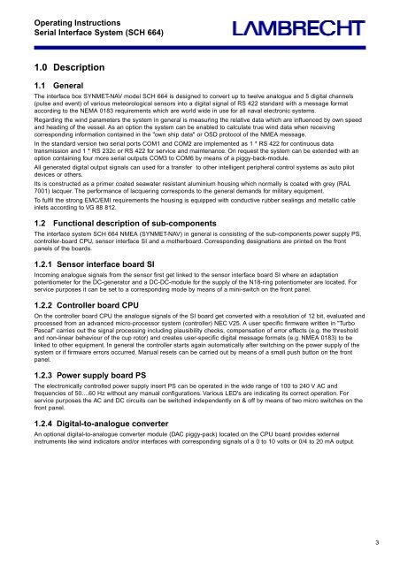
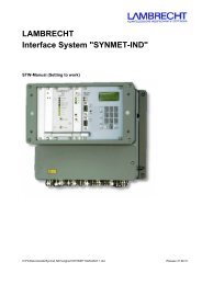
The interface box <strong>SYNMET</strong>-<strong>NAV</strong> model <strong>SCH</strong> <strong>664</strong> is designed to convert up to twelve analogue and 5 digital channels<br />
(pulse and event) of various meteorological sensors into a digital signal of <strong>RS</strong> <strong>422</strong> standard with a message format<br />
according to the NEMA 0183 requirements which are world wide in use for all naval electronic systems.<br />
Regarding the wind parameters the system in general is measuring the relative data which are influenced by own speed<br />
and heading of the vessel. As an option the system can be enabled to calculate true wind data when receiving<br />
corresponding information contained in the "own ship data" or OSD protocol of the NMEA message.<br />
In the standard version two serial ports COM1 and COM2 are implemented as 1 * <strong>RS</strong> <strong>422</strong> for continuous data<br />
transmission and 1 * <strong>RS</strong> 232c or <strong>RS</strong> <strong>422</strong> for service and maintenance. On request the system can be extended with an<br />
option containing four more serial outputs COM3 to COM6 by means of a piggy-back-module.<br />
All generated digital output signals can used for a transfer to other intelligent peripheral control systems as auto pilot<br />
devices or others.<br />
Its is constructed as a primer coated seawater resistant aluminium housing which normally is coated with grey (RAL<br />
7001) lacquer. The performance of lacquering corresponds to the general demands for military equipment.<br />
To fulfil the strong EMC/EMI requirements the housing is equipped with conductive rubber sealings and metallic cable<br />
inlets according to VG 88 812.<br />
1.2 Functional description of sub-components<br />
The interface system <strong>SCH</strong> <strong>664</strong> NMEA (<strong>SYNMET</strong>-<strong>NAV</strong>) in general is consisting of the sub-components power supply PS,<br />
controller-board CPU, sensor interface SI and a motherboard. Corresponding designations are printed on the front<br />
panels of the boards.<br />
1.2.1 Sensor interface board SI<br />
Incoming analogue signals from the sensor first get linked to the sensor interface board SI where an adaptation<br />
potentiometer for the DC-generator and a DC-DC-module for the supply of the N18-ring potentiometer are located. For<br />
service purposes it can be set to a corresponding mode by means of a mini-switch on the front panel.<br />
1.2.2 Controller board CPU<br />
On the controller board CPU the analogue signals of the SI board get converted with a resolution of 12 bit, evaluated and<br />
processed from an advanced micro-processor system (controller) NEC V25. A user specific firmware written in "Turbo<br />
Pascal" carries out the signal processing including plausibility checks, compensation of error effects (e.g. the threshold<br />
and non-linear behaviour of the cup rotor) and creates user-specific digital message formats (e.g. NMEA 0183) to be<br />
linked to other equipment. In general the controller starts again automatically after switching on the power supply of the<br />
system or if firmware errors occurred. Manual resets can be carried out by means of a small push button on the front<br />
panel.<br />
1.2.3 Power supply board PS<br />
The electronically controlled power supply insert PS can be operated in the wide range of 100 to 240 V AC and<br />
frequencies of 50....60 Hz without any manual configurations. Various LED's are indicating its correct operation. For<br />
service purposes the AC and DC circuits can be switched independently on & off by means of two micro switches on the<br />
front panel.<br />
1.2.4 Digital-to-analogue converter<br />
An optional digital-to-analogue converter module (DAC piggy-pack) located on the CPU board provides external<br />
instruments like wind indicators and/or interfaces with corresponding signals of a 0 to 10 volts or 0/4 to 20 mA output.<br />
3


