Serial Interface System RS 422 SYNMET / NAV (SCH 664) - Windaus
Serial Interface System RS 422 SYNMET / NAV (SCH 664) - Windaus
Serial Interface System RS 422 SYNMET / NAV (SCH 664) - Windaus

You also want an ePaper? Increase the reach of your titles
YUMPU automatically turns print PDFs into web optimized ePapers that Google loves.
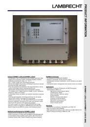
Operating Instructions<br />
<strong>Serial</strong> <strong>Interface</strong> <strong>System</strong> (<strong>SCH</strong> <strong>664</strong>)<br />
2.6 Setting into operation<br />
After having finished the mechanical and electrical installation the whole cabling should be checked before switching on<br />
the mains respectively the circuit breaker for the anemometer system.<br />
Further switches for service purposes are located on the front panels of the boards. Please get sure they are in the ONposition<br />
for operation.<br />
Due to some intelligent internal self-check and automatic adjustment routines of the equipment no alignments have to be<br />
carried out by the user after the first installation or the replacement of any spares.<br />
Apart from wind sensor heating devices all other power supply of external sensor electronic circuits if required will be<br />
provided by the in-built DC/DC converters in the system and therefore separate AC converters are not required.<br />
The controller of the interface system has an automatic self-start routine in order to start it automatically after switching<br />
on the power. Same process gets in function also after mains failures e.t.c.<br />
The operation will be indicated by two LED's (designations: DA = data acquisition; DP = data processing) on the front<br />
panel of the CPU.<br />
Only in case of strong interference causing software errors the reset button can be pressed in order to re-start the<br />
internal firmware manually.<br />
2.7 Performance checks<br />
First of all it has to be ensured that all three mini-switches on the front-panel are in the on position. The two red LED's on<br />
the CPU board have to flash in clockwise intervals.<br />
The measuring values obtained from the external display consoles can be compered with measurements from other<br />
meteorological sensors on land or from other vessels in the neighbourhood.<br />
More detailed test procedures about this subject are mentioned in the documentation for factory acceptance test (FAT),<br />
harbour acceptance test (HAT) and sea acceptance test (SAT).<br />
More circumference service and maintenance works can be carried out by means of a special simulation and test<br />
equipment (STE) LAMBRECHT model No. <strong>SCH</strong> 463 Mark II which is available to be purchased as an option. Details for<br />
its use are described in an own operation manual.<br />
In general the procedures have to be carried out at least by two people from the maintenance staff. For the vocal<br />
communication between the external sensor located on the mast and a wind data display console a pair of portable<br />
tranceivers (walky-talkies) or similar are recommended.<br />
2.8 Message format standard<br />
All meteorological data of our <strong>SYNMET</strong>-<strong>NAV</strong> interface system get transmitted to others in a message format according to<br />
the NMEA 0183 standards which are world-wide in use on civil and naval systems.<br />
The standardised message is containing of the elements start sign, talker device identifier, sentence formatters,<br />
measuring value(s), field delimiters, check sums and other signs.<br />
According to the nomenclature of the National Marine Electronics Association (NMEA) all equipment generating such<br />
messages is designated as a "talker" whereas the receiving system is called a "listener".<br />
All project specific data and parameters are described in detail in a separate agreement of the <strong>Interface</strong> Design<br />
Specification IDS or a similar document which is signed by the buyer and the manufacturer.<br />
2.9 Built-in test facility = BITE-facility<br />
A built-in test (BITE-) facility enables the user to detect various failures of the measuring system in case of malfunctions.<br />
The designation of faulty values and errors is described in detail in the <strong>Interface</strong> Design Specification (IDS) Document as<br />
mentioned above.<br />
7