Serial Interface System RS 422 SYNMET / NAV (SCH 664) - Windaus
Serial Interface System RS 422 SYNMET / NAV (SCH 664) - Windaus
Serial Interface System RS 422 SYNMET / NAV (SCH 664) - Windaus

Create successful ePaper yourself
Turn your PDF publications into a flip-book with our unique Google optimized e-Paper software.
4<br />
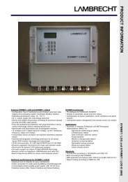
Operating Instructions<br />
<strong>Serial</strong> <strong>Interface</strong> <strong>System</strong> (<strong>SCH</strong> <strong>664</strong>)<br />
1.3 Control and operation elements<br />
For the continuous operation of the interface system special manual operations e.g. on a keyboard are not necessary.<br />
Only for servicing and checks the inserted printed circuit boards are fitted with the green and red control LED's and<br />
switches as described below (see also the "drawing of front panels" on the following page).<br />
Sensor interface board - SI<br />
LED indications:<br />
(U1/U2) Indicates the presence of the power supply of 12 V DC for the N18-ring potentiometer of the wind sensor or<br />
other consumers e.g. sensors to be supplied from integrated DC/DC modules of the system.<br />
(U3) Output U3 is not in use - the LED is off<br />
(service) Indicates that the switch is set to the service mode - please refer to the switch function as described below<br />
Switch<br />
(operation) Effects an event message for internal mean value calculation only in the data acquisition mode of the<br />
system; in the service position the LED is shining.<br />
When working as a talker of NMEA 0183 messages the function is not in use for this application<br />
CPU board - CPU<br />
LED indicators:<br />
(DA) Data acquisition LED is indicating the sampling of data from the sensor. Depending on the stipulated<br />
sampling rate it is flashing up to six times per second.<br />
(DP) Data processing LED is indicating the generation of NMEA 0183 data protocols. Depending on the<br />
stipulated transmission rate it is flashing at least once per second.<br />
Remark: In case of errors the LED will shine constantly or not at all<br />
Button Reset of the controller system<br />
Connectors: COM1/COM2 9-pole female sub-D connectors for service and maintenance only<br />
Power supply board - PS<br />
LED indicators:<br />
(AC-power) Power input is connected and switched on<br />
(DC output) Internal DC supply is switched on<br />
(+ 5 V) +5 V DC output of the module is present<br />
(+12 V) +12 V DC output of the module is present<br />
(-12 V) -12 V output of the module is present<br />
Remark: For a proper operation of the whole system all indication LED's mentioned her have to be illuminated (on).<br />
The remaining LED's (solar), (battery charge) and (DC-output) are not in use in this application<br />
Switches:<br />
(AC-power) With these items an independent switching of AC input voltage and DC output voltage is possible -<br />
(DC-output) for operation both have to be in the "On" position.