Motor Protection MS 220 DA/ MCB 112 VLT® PTC ... - ziehl.de
Motor Protection MS 220 DA/ MCB 112 VLT® PTC ... - ziehl.de
Motor Protection MS 220 DA/ MCB 112 VLT® PTC ... - ziehl.de

You also want an ePaper? Increase the reach of your titles
YUMPU automatically turns print PDFs into web optimized ePapers that Google loves.
6<br />
6 Install the <strong>MS</strong> <strong>220</strong> <strong>DA</strong> Option in the Frequency<br />
Converter <strong>Motor</strong> <strong>Protection</strong> <strong>MS</strong> <strong>220</strong> <strong>DA</strong><br />
- The plastic cover must point downwards.<br />
- Connect the motor resistor (thermistor) to terminals T1 and T2 of the <strong>MS</strong> <strong>220</strong> <strong>DA</strong>. Open jumper 12-37 on the frequency converter and connect<br />
terminal X44/12 on the <strong>MS</strong> <strong>220</strong> <strong>DA</strong> with terminal 37 (Safe Stop) on the frequency converter (see Photo 4). Only then can the VLT AutomationDrive<br />
FC 302 be safely shut down in the case of malfunction. The output on terminal X44/12 of the <strong>MS</strong> <strong>220</strong> <strong>DA</strong> must always be wired into the chain<br />
on the Safe Stop input on terminal 37 on the frequency converter in or<strong>de</strong>r to ensure shutdown of power in case of malfunction.<br />
- Continue the necessary wiring of the <strong>MS</strong> <strong>220</strong> <strong>DA</strong>. See connection diagram in section 1.2.<br />
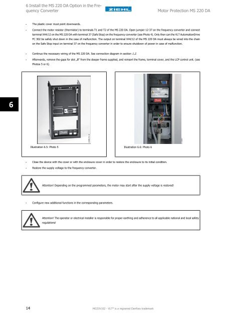
- Afterwards, remove the gaps for slot „B“ from the <strong>de</strong>eper frame supplied, and reinsert the frame, terminal cover, and the LCP control unit. (see<br />
Photos 5 or 6)<br />
Illustration 6.5: Photo 5 Illustration 6.6: Photo 6<br />
- Close the <strong>de</strong>vice with the cover or with the enclosure cover in or<strong>de</strong>r to restore the enclosure to its initial condition.<br />
- Restore the supply voltage to the frequency converter.<br />
Attention! Depending on the programmed parameters, the motor may start after the supply voltage is restored!<br />
- Configure new additional functions in the corresponding parameters.<br />
Attention! The operator or electrical installer is responsible for proper earthing and adherence to all applicable national and local safety<br />
regulations!<br />
14 MG33V102 - VLT ® is a regisered Danfoss tra<strong>de</strong>mark