Motor Protection MS 220 DA/ MCB 112 VLT® PTC ... - ziehl.de
Motor Protection MS 220 DA/ MCB 112 VLT® PTC ... - ziehl.de
Motor Protection MS 220 DA/ MCB 112 VLT® PTC ... - ziehl.de

Create successful ePaper yourself
Turn your PDF publications into a flip-book with our unique Google optimized e-Paper software.
4<br />
4 How to Install <strong>MCB</strong> <strong>112</strong> VLT ® <strong>PTC</strong> Thermistor Option<br />
• Continue the necessary wiring of the <strong>MCB</strong> <strong>112</strong> VLT <strong>PTC</strong> Thermistor Card. See Connection Schematic in the previous chapter and in the chapter<br />
Application Examples.<br />
• Afterwards, remove the gaps for slot "B" from the <strong>de</strong>eper frame supplied, and reinsert the frame, terminal cover, and the LCP control unit.<br />
• Close the <strong>de</strong>vice with the cover or with the enclosure cover in or<strong>de</strong>r to restore the enclosure to its initial condition.<br />
• Restore the power supply to the frequency converter.<br />
• Configure new additional functions in the corresponding parameters.<br />
Warning! Depending on the settings in par 5-19, the motor may start after the power supply voltage is restored!<br />
Warning! The operator or the electrical installer is responsible for proper earthing and adherence to all applicable national and local<br />
safety regulations!<br />
4.1.3 Installation of a Category 0 Stop<br />
To carry out an installation of a Category 0 Stop (EN 60204-1) in conformity with Safety Category 3, follow these instructions:<br />
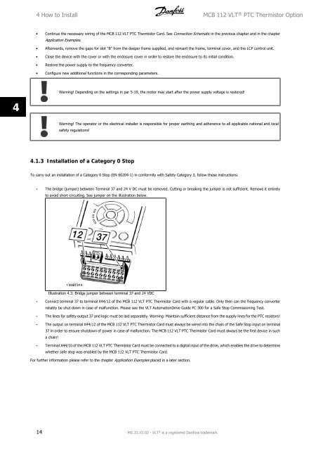
- The bridge (jumper) between Terminal 37 and 24 V DC must be removed. Cutting or breaking the jumper is not sufficient. Remove it entirely<br />
to avoid short-circuiting. See jumper on the illustration below.<br />
Illustration 4.3: Bridge jumper between terminal 37 and 24 VDC<br />
- Connect terminal 37 to terminal X44/12 of the <strong>MCB</strong> <strong>112</strong> VLT <strong>PTC</strong> Thermistor Card with a regular cable. Only then can the frequency converter<br />
reliably be shut down in case of malfunction. Please see the VLT AutomationDrive Gui<strong>de</strong> FC 300 for a Safe Stop Commissioning Test.<br />
- The lines for safety output 37 and logic must be laid separately. Warning: Maintain sufficient distance from the supply lines for the <strong>PTC</strong> resistors!<br />
- The output on terminal X44/12 of the <strong>MCB</strong> <strong>112</strong> VLT <strong>PTC</strong> Thermistor Card must always be wired into the chain of the Safe Stop input on terminal<br />
37 in or<strong>de</strong>r to ensure shutdown of power in case of malfunction. The <strong>MCB</strong> <strong>112</strong> VLT <strong>PTC</strong> Thermistor Card must always be the first <strong>de</strong>vice in such<br />
a chain!<br />
- Terminal X44/10 of the <strong>MCB</strong> <strong>112</strong> VLT <strong>PTC</strong> Thermistor Card must be connected to a digital input of the drive, which enables the drive to <strong>de</strong>termine<br />
whether safe stop was enabled by the <strong>MCB</strong> <strong>112</strong> VLT <strong>PTC</strong> Thermistor Card.<br />
For further information please refer to the chapter Application Examples placed in a later section.<br />
14 MG.33.V2.02 - VLT ® is a registered Danfoss tra<strong>de</strong>mark