HOME GYM OWNER'S MANUAL - Horizon Fitness
HOME GYM OWNER'S MANUAL - Horizon Fitness
HOME GYM OWNER'S MANUAL - Horizon Fitness

Create successful ePaper yourself
Turn your PDF publications into a flip-book with our unique Google optimized e-Paper software.
TORUS 4<br />
<strong>HOME</strong> <strong>GYM</strong> OWNER’S <strong>MANUAL</strong>
INTRODUCTION<br />
CONGRATULATIONS and THANK YOU for your purchase of this <strong>Horizon</strong> home gym! Whether your goal is to tone your muscles,<br />
increase your strength or simply enjoy a fuller, healthier ifestyle, a <strong>Horizon</strong> home gym can help you attain it – adding club-quality<br />
performance to your at-home workouts, with the ergonomics and innovative features you need to get stronger and healthier, faster.<br />
Because we’re committed to designing fitness equipment from the inside out, we use only the highest quality components. It’s a<br />
commitment we back with one of the strongest warranty packages in the industry.<br />
You want exercise equipment that offers the most comfort, the best reliability and the highest quality in its class.<br />
A <strong>Horizon</strong> home gym delivers.<br />
IMPORTANT SAFETY PRECAUTIONS<br />
FOR HOUSEHOLD USE ONLY<br />
SAVE THESE INSTRUCTIONS<br />
Read all instructions before using this home gym. Basic precautions should always be followed, including the following: Read all<br />
instructions before using this home gym. It is the responsibility of the owner to ensure that all users of this home gym are adequately<br />
informed of all warnings and precautions. If you have any questions after reading this manual, contact customer service at the<br />
number listed on the back cover of this manual.<br />
WARNING<br />
TO REDUCE THE RISK OF INJURY TO PERSONS:<br />
• Close supervision is necessary when this home gym is used by, on, or near children, invalids, or disabled persons.<br />
• Use this appliance (or home gym) only for its intended use as described in this manual. Do not use attachments not<br />
recommended by the manufacturer.<br />
• Never drop or insert any object into any opening.<br />
• If you experience any kind of pain, including but not limited to chest pains, nausea, dizziness, or shortness of breath, stop<br />
exercising immediately and consult your physician before continuing.<br />
• Do not wear clothes that might catch on any part of the home gym.<br />
• Always wear athletic shoes while using this equipment.<br />
• Do not jump on the home gym.<br />
• At no time should more than one person be on home gym while in operation.<br />
• The home gym should not be used by persons weighing more than 300 pounds. Failure to comply will void the warranty.<br />
• The home gym is intended for in-home use only.<br />
• Do not use this home gym in any commercial, rental, school or institutional setting. Failure to comply will void the warranty.Do<br />
not use outdoors.<br />
At NO time should pets or children under the age of 12 be closer to the home gym than 10 feet.<br />
At NO time should children under the age of 12 use the home gym.<br />
Children over the age of 12 should not use the home gym without adult supervision.<br />
3
ASSEMBLY<br />
IMPORTANT: READ THESE SAFETY INSTRUCTIONS BEFORE USE!<br />
WARNING<br />
During the assembly process there are several areas that special attention must be paid. It is very important to follow the assembly<br />
instructions correctly and to make sure all parts are firmly tightened. If the assembly instructions are not followed correctly, the<br />
home gym could have frame parts that are not tightened and will seem loose and may cause irritating noises. There should be<br />
no side-to-side play in the frame uprights. If there is any play in these areas, the home gym has not been properly assembled. To<br />
prevent damage to the home gym, the assembly instructions must be reviewed and corrective actions should be taken.<br />
UNPACKING<br />
Place the home gym carton on a level flat surface. It is recommended that you place a protective covering on your floor. Take<br />
CAUTION when handling and transporting this unit. Never open box when it is on its side. Unpack the unit where it will be used.<br />
FAILURE TO FOLLOW THESE INSTRUCTIONS COULD RESULT IN INJURY!<br />
Before proceeding, find your home gym’s serial number and model name located on the<br />
left rear side of the base frame and enter it in the space provided below.<br />
ENTER YOUR SERIAL NUMBER AND MODEL NAME IN THE BOXES BELOW:<br />
SERIAL NUMBER:<br />
MODEL NAME: HORIzON<br />
* Refer to the SERIAL NUMBER and MODEL NAME when calling for service.<br />
* Also enter this serial number on your Warranty Card.<br />
SERIAL NUMBER LOCATION<br />
5
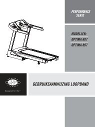
CABLE “A”<br />
LAT PULLDOWN BAR<br />
LAT BAR BRACKET ASSEMBLY<br />
CENTER SUPPORT FRAME<br />
MAIN SUPPORT FRAME (RIGHT)<br />
CABLE “C”<br />
RADIAL ARM ADJUSTMENT PIN<br />
SEAT BACK PAD<br />
SEAT BOTTOM PAD<br />
SEAT ASSEMBLY<br />
SEAT HEIGHT<br />
ADJUSTMENT KNOB<br />
FOAM LEGROLLERS<br />
UPPER PULLEY ASSEMBLY<br />
DUAL FLOATING PULLEY BRACKET<br />
WEIGHT SHIELD<br />
GUIDE ROD<br />
RADIAL ARM ASSEMBLY<br />
WEIGHT SELECTION PIN<br />
MAIN SUPPORT FRAME (LEFT)<br />
SINGLE FLOATING PULLEY BRACKET<br />
SEAT ASSEMBLY SAFETY PIN<br />
BASE FRAME<br />
ADJUSTABLE FOOTPLATE CABLE “B”<br />
TOOLS INCLUDED:<br />
Screwdriver<br />
19 mm Flat Wrench<br />
13 mm/17 mm Flat Wrench<br />
4 mm Allen Wrench<br />
6 mm Allen Wrench<br />
8 mm Allen Wrench<br />
PARTS INCLUDED:<br />
1 Seat Assembly Safety Pin<br />
2 Foam Rollers<br />
1 Seat Back Cushion<br />
1 Main Base Frame<br />
1 Main Support Frame (Right)<br />
1 Main Support Frame (Left)<br />
1 Radial Arm Assembly<br />
1 Center Upright<br />
1 Seat Assembly<br />
3 Weight Shields<br />
2 Guide Rods<br />
1 Weight Selection Pin<br />
1 Upper Pulley Bracket<br />
1 Dual Floating Pulley Bracket<br />
1 Single Floating Pulley Bracket<br />
1 Upper Pulley Assembly<br />
3 Cables<br />
1 Nylon Ankle Strap<br />
2 Handles<br />
1 Lat Pulldown Bar<br />
9 Hardware Bags<br />
PRE ASSEMBLY<br />
UNPACKING<br />
Unpack the product where you will be using it. Place the bench on a level flat surface.<br />
It is recommended that you place a protective covering on your floor. Never open box<br />
when it is on its side.<br />
NOTE: During each assembly step, ensure that ALL nuts and bolts are in place and<br />
partially threaded in before completely tightening any ONE bolt.<br />
NOTE: A light application of grease may aid in the installation of hardware. Any grease,<br />
such as lithium bike grease is recommended.<br />
NEED HELP?<br />
If you have questions or if<br />
there are any missing parts,<br />
contact Customer Tech<br />
Support.<br />
6 7
ASSEMBLY STEP 1<br />
CENTER SUPPORT<br />
FRAME<br />
MAIN SUPPORT<br />
FRAME (RIGHT)<br />
MAIN SUPPORT<br />
FRAME (LEFT)<br />
BASE FRAME<br />
NYLON NUT (C)<br />
FLAT WASHER (B)<br />
A Place BASE FRAME on floor in desired location.<br />
B Remove 6 NYLON NUTS (C) and 6 FLAT WASHERS<br />
(B) from BASE FRAME.<br />
C Attach RIGHT MAIN SUPPORT FRAME to right side<br />
of BASE FRAME using 2 FLAT WASHERS (B) and 2<br />
NYLON NUTS (C).<br />
D Repeat on other side.<br />
E Attach CENTER SUPPORT FRAME to BASE FRAME<br />
using 2 FLAT WASHERS (B) and 2 NYLON NUTS (C).<br />
ASSEMBLY STEP 2<br />
BOLT (D)<br />
FLAT WASHER (B)<br />
LAT BAR<br />
BRACKET ASSEMBLY<br />
FLAT WASHER (B)<br />
8 9<br />
NYLON NUT (C)<br />
UPPER PULLEY ASSEMBLY<br />
NYLON NUT (C)<br />
FLAT WASHER (B)<br />
FLAT WASHER (B)<br />
BOLT (A)<br />
SUPPORT<br />
PLATE<br />
BOLT (A)<br />
Qty: 4<br />
NYLON NUT (C)<br />
Qty: 6<br />
HARDWARE BAG 1 CONTENTS:<br />
A Open HARDWARE BAG 1.<br />
FLAT WASHER (B)<br />
Qty: 12<br />
BOLT (D)<br />
Qty: 2<br />
SUPPORT PLATE<br />
Qty: 2<br />
B Attach UPPER PULLEY ASSEMBLY to CENTER<br />
SUPPORT FRAME using 2 BOLTS (D), 4 FLAT<br />
WASHERS (B) and 2 NYLON NUTS (C). Tighten this<br />
hardware.<br />
C Position LAT BAR BRACKET ASSEMBLY in line<br />
with the UPPER PULLEY ASSEMBLY and the LEFT<br />
SUPPORT FRAME and RIGHT SUPPORT FRAME as<br />
shown. Using 4 BOLTS (A), 8 FLAT WASHERS (B) and<br />
4 NYLON NUTS (C) attach SUPPORT PLATES, LAT<br />
BAR BRACKET ASSEMBLY and UPPER PULLEY<br />
ASSEMBLY to the LEFT SUPPORT FRAME and<br />
RIGHT SUPPORT FRAME as shown.
ASSEMBLY STEP 3<br />
FRONT COVER<br />
FLAT WASHER (B)<br />
BOLT (A)<br />
SEAT WELDMENT SET<br />
SCREW (F)<br />
BACK COVER<br />
FLAT WASHER (B)<br />
NYLON NUT (C)<br />
RADIAL ARM<br />
ASSEMBLY<br />
STEP 3-D: INSTALLING THE STOPPER:<br />
RADIAL ARM ASSEMBLY<br />
STOPPER<br />
HARDWARE BAG 2 CONTENTS:<br />
BOLT (A)<br />
Qty: 2<br />
NYLON NUT (C)<br />
Qty: 2<br />
A Open HARDWARE BAG 2.<br />
B Attach SEAT WELDMENT SET.<br />
FLAT WASHER (B)<br />
Qty: 4<br />
SCREW (F)<br />
Qty: 4<br />
C Attach COVER to bolted joint using 4 SCREWS (F).<br />
D Remove STOPPER from front side of RADIAL ARM<br />
ASSEMBLY and reinstall on back side of RADIAL<br />
ARM ASSMBLY. Attach RADIAL ARM ASSEMBLY<br />
to CENTER SUPPORT FRAME using 2 BOLTS (A), 4<br />
FLAT WASHER (B) and 2 NYLON NUT (C).<br />
ASSEMBLY STEP 4<br />
SEAT SET SAFETY PIN<br />
NYLON NUT (C)<br />
FLAT WASHER (B)<br />
SEAT WELDMENT SET<br />
BOLT (G)<br />
FLAT WASHER (B)<br />
LEG EXTENSION/<br />
CURL DOWN TUBE<br />
CENTER SUPPORT FRAME<br />
CABLE ATTACHMENT<br />
HARDWARE BAG 3 CONTENTS:<br />
FLAT WASHER (B)<br />
Qty: 2<br />
10 11<br />
BOLT (G)<br />
Qty: 1<br />
A Open HARDWARE BAG 3.<br />
NYLON NUT (C)<br />
Qty: 1<br />
B Attach LEG ExTENSION/CURL DOWN TUBE<br />
to SEAT ASSEMBLY using 1 BOLT (G), 2 FLAT<br />
WASHERS (B) and 1 NYLON NUT (C).<br />
NOTE: Position the LEG ExTENSION/CURL DOWN<br />
TUBE so the cable attachment is facing the gym.<br />
C Insert SEAT SET SAFETY PIN.
ASSEMBLY STEP 5<br />
SEAT BACK PAD<br />
SEAT BOTTOM PAD<br />
NYLON NUT (C)<br />
FLAT WASHER (B)<br />
END COVER<br />
LEG PAD<br />
LEG EXTENSION/<br />
CURL DOWN TUBE<br />
BOLT (N)<br />
FLAT WASHER (B)<br />
SCREW (H)<br />
FLAT WASHER (B)<br />
Qty: 6<br />
HARDWARE BAG 4 CONTENTS: HARDWARE BAG 5 CONTENTS:<br />
A Open HARDWARE BAG 4.<br />
BOLT (N)<br />
Qty: 2<br />
SCREW (H)<br />
Qty: 2<br />
B Attach SEAT BACK PAD to CENTER SUPPORT<br />
FRAME using 2 SCREWS (H), 2 FLAT WASHERS<br />
(B).<br />
C Attach SEAT BOTTOM PAD to SEAT WELDMENT<br />
using 2 BOLTS (D), 4 FLAT WASHERS (B) and 2<br />
NYLON NUTS (C).<br />
D Install assembled seat into gym.<br />
E Install LEG PADS to LEG ExTENSION/CURL DOWN<br />
TUBE as shown in diagram.<br />
ASSEMBLY STEP 6<br />
FLAT WASHER (J)<br />
INCREMENT WEIGHT<br />
BACK SHROUD PLATE<br />
SCREW (I)<br />
FLAT WASHER (J)<br />
Qty: 8<br />
12 13<br />
FLAT WASHER (J)<br />
NYLON NUT (K)<br />
SELECTOR PIN<br />
GUIDE ROD<br />
TOP WEIGHT<br />
BAYONET<br />
WEIGHT PLATE<br />
BUMPER<br />
SCREW (I)<br />
FLAT WASHER (J)<br />
BACK SHROUD PLATE<br />
BOLT (I)<br />
Qty: 4<br />
NYLON NUT (K)<br />
Qty: 4<br />
BUMPER<br />
Qty: 2<br />
A Open HARDWARE BAG 5.<br />
B Insert each GUIDE ROD into the BASE FRAME as shown<br />
in diagram.<br />
C Install rubber BUMPER onto each GUIDE ROD.<br />
D Install each WEIGHT PLATE onto GUIDE RODS. NOTE:<br />
Ensure that each WEIGHT PLATE’s selector pin slot faces<br />
downward.<br />
E Insert each GUIDE ROD into the corresponding hole in the<br />
UPPER PULLEY ASSEMBLY.<br />
F Secure GUIDE RODS and BACK SHROUD PLATE in<br />
UPPER PULLEY ASSEMBLY using 2 BOLTS (I), 4 FLAT<br />
WASHERS (J) and 2 NYLON NUTS (K) as shown in<br />
diagram.<br />
NOTE: Ensure that each bolt is inserted through the hole at<br />
the top of the GUIDE ROD.<br />
G Install BACK SHROUD PLATE into the BASE FRAME<br />
using 2 BOLTS (I), 4 FLAT WASHERS (J) and 2 NYLON<br />
NUTS (K) as shown in diagram.<br />
H Tighten all hardware.
ASSEMBLY STEP 7<br />
FLAT WASHER (B)<br />
NYLON NUT (C) BALL<br />
RUBBER STOP<br />
HOOK<br />
LAT BAR<br />
DUAL FLOATING<br />
PULLEY BRACKET<br />
CLEVIS<br />
FLAT WASHER (B)<br />
SCREW (E)<br />
CABLE A<br />
LAT BAR / WEIGHT<br />
CABLE SCREW AND NUT<br />
TOP WEIGHT<br />
THREAD<br />
HARDWARE BAG 6 CONTENTS: NYLON NUT (C)<br />
FLAT WASHER (B)<br />
HARDWARE BAG 7 CONTENTS:<br />
CABLE A<br />
Qty: 1<br />
A Open HARDWARE BAG 6.<br />
B Remove nylon nut and threaded screw from end of<br />
CABLE A.<br />
C Insert cable end into LAT BAR ASSEMBLY BRACKET<br />
pulley as shown in diagram.<br />
NOTE: After passing through second pulley bracket,<br />
DUAL FLOATING PULLEY BRACKET must be installed.<br />
D Re-install threaded screw and nylon nut before threading<br />
cable into TOP WEIGHT PLATE.<br />
NOTE: Always maintain at least ½˝ of weight cable screw<br />
in TOP WEIGHT PLATE for saftey.<br />
E Hook LAT BAR on to cable using the HOOK and rest in<br />
craddle.<br />
ASSEMBLY STEP 8<br />
14 15<br />
HOOK<br />
GRIP<br />
RUBBER STOP<br />
BALL<br />
CLEVIS<br />
SCREW (E)<br />
FLAT WASHER (B)<br />
CABLE B<br />
CABLE B<br />
Qty: 1<br />
A Open HARDWARE BAG 7.<br />
B Remove nylon nut, threaded screw and ball from end of<br />
CABLE B.<br />
C Route CABLE B through the pulley system in the<br />
RADIAL ARM ASSEMBLY as shown in diagram.<br />
D After CABLE B routing is complete replace nylon nut,<br />
threaded screw and ball on end of cable.<br />
E Hook HANDLES on to cable using the 2 HOOKS.
ASSEMBLY STEP 9<br />
NYLON<br />
NUT (C)<br />
CABLE C<br />
FLAT WASHER (B)<br />
RUBBER STOP<br />
BALL<br />
CLEVIS<br />
FLAT WASHER (B)<br />
SCREW (E)<br />
HOOK<br />
EXTENSION CABLE<br />
LEG EXTENSION/<br />
CURL DOWN TUBE<br />
CABLE SCREW<br />
SINGLE FLOATING<br />
PULLEY BRACKET<br />
HARDWARE BAG 8 CONTENTS: HARDWARE BAG 9 CONTENTS:<br />
FLAT WASHER (M)<br />
SCREW (L)<br />
CABLE C<br />
Qty: 1<br />
A Open HARDWARE BAG 8.<br />
B Remove nylon nut, threaded screw and ball from end of<br />
CABLE C.<br />
C Attach threaded cable end to SINGLE FLOATING<br />
PULLEY BRACKET.<br />
D Route CABLE C through pulley system of BASE FRAME<br />
up through the DUAL FLOATING PULLEY BRACKET<br />
and back to BASE FRAME and CENTER SUPPORT<br />
FRAME as shown in diagram.<br />
E After CABLE C routing is complete replace nylon nut,<br />
threaded screw and ball on end of cable.<br />
F Hook the LEG EXTENSION/CURL DOWN TUBE<br />
to the end of the cable using the HOOK and the<br />
EXTENSION CABLE.<br />
ASSEMBLY STEP 10<br />
FLAT WASHER (M)<br />
Qty: 12<br />
16 17<br />
RIGHT SHROUD<br />
BACK SHROUD<br />
LEFT SHROUD<br />
FLAT WASHER (M)<br />
SCREW (L)<br />
SCREW (L)<br />
Qty: 12<br />
A Open HARDWARE BAG 9.<br />
B Install WEIGHT SHROUDS as shown in diagram, using<br />
12 SCREWS (L) and 12 FLAT WASHERS (M).
ASSEMBLY COMPLETE!<br />
BEFORE YOU BEGIN<br />
CONGRATULATIONS! on choosing your home gym. You’ve taken an important step in developing and sustaining an exercise<br />
program! Your home gym is a tremendously effective tool for achieving your personal fitness goals. Regular use of your home gym<br />
can improve the quality of your life in so many ways.<br />
HERE ARE JUST A FEW OF THE HEALTH BENEFITS OF ExERCISE:<br />
• Improved Muscle Tone and Strength<br />
• Increased Daily Energy Levels<br />
• A Healthier Heart<br />
• Weight Loss<br />
The key to reaping these benefits is to develop an exercise habit. Your new home gym will help you eliminate obstacles that prevent<br />
you from exercising. Inclement weather and darkness won’t interfere with your workout when you use your home gym in the comfort<br />
of your home. This guide provides you with basic information for using and enjoying your new machine.<br />
LOCATION OF THE <strong>HOME</strong> <strong>GYM</strong><br />
Place the home gym on a level surface. There should be 1 foot of clearance behind the home gym,<br />
3 feet on each side and 3 feet in front. Do not place the home gym in any area that will block any<br />
vent or air openings. The home gym should not be located outdoors.<br />
WARNING<br />
SEAT ASSEMBLY PIN<br />
Ensure that the seat assermbly safety pin is fully inserted before using the home gym. Failure to<br />
do so may result in injury!<br />
PROPER USAGE<br />
Make sure to follow the MAINTENANCE schedule in this manual. Stop your workout immediately if you feel pain, faint, dizzy or are<br />
short of breath.<br />
WARNING<br />
Do not operate the home gym if there is any noticable damage to the cables or pulleys. If any damage is noticable, contact customer<br />
tech support at the number located on the back panel of this manual.<br />
18 19<br />
3 feet<br />
Front<br />
3 feet<br />
Back<br />
1 foot<br />
3 feet
CONDITIONING GUIDELINES<br />
ALWAYS CONSULT YOUR PHYSICIAN BEFORE BEGINNING AN ExERCISE PROGRAM.<br />
HOW OFTEN? (Frequency of Workouts)<br />
The American Heart Association recommends that you exercise at least 3 to 4 days per week to maintain fitness. If you have other<br />
goals such as weight or fat loss, you will achieve your goal faster with more frequent exercise. Whether it’s 3 days or 6 days,<br />
remember that your ultimate goal should be to make exercise a lifetime habit. Many people are successful staying with a fitness<br />
program if they set aside a specific time of day to exercise. It doesn’t matter whether it’s in the morning before breakfast, during<br />
lunch hour or while watching the evening news. What’s more important is that it’s a time that allows you to keep a schedule, and a<br />
time when you won’t be interrupted. To be successful with your fitness program, you have to make it a priority in your life. So decide<br />
on a time, pull out your day planner and pencil in your exercise times for the next month!<br />
HOW LONG? (Duration of Workouts)<br />
For aerobic exercise benefits, it’s recommended that you exercise from between 24 and 60 minutes per session. But start slowly and<br />
gradually increase your exercise times. If you’ve been sedentary during the past year, it may be a good idea to keep your exercise<br />
times to as little as 5 minutes initially. Your body will need time to adjust to the new activity. If your goal is weight loss, a longer<br />
exercise session at lower intensities has been found to be most effective.<br />
HOW HARD? (Intensity of Workouts)<br />
How hard you workout is also determined by your goals. If you use your home gym to prepare for a 5K run, you will probably work<br />
out at a higher intensity than if your goal is general fitness. Regardless of your long term goals, always begin an exercise program at<br />
low intensity. Aerobic exercise does not have to be painful to be beneficial! There are two ways to measure your exercise intensity.<br />
The first is by monitoring your heart rate (using the grip pulse handlebars or a wireless chest transmitter - may be sold separately),<br />
and the second is by evaluating your perceived exertion level (this is simpler than it sounds!).<br />
PERCEIVED ExERTION LEVEL<br />
A simple way to gauge your exercise intensity is to evaluate your perceived exertion level. While exercising, if you are too winded to<br />
maintain a conversation without gasping, you are working out too hard. A good rule of thumb is to work to the point of exhilaration,<br />
not exhaustion. If you cannot catch your breath, it’s time to slow down. Always be aware of these warning signs of overexertion.<br />
GENERAL STRENGTH TRAINING GUIDELINES<br />
• It is recommended that you perform at least 5-10 minutes of cardiovascular exercise before beginning your strength routine in<br />
order to warm the muscles, increase the heart rate, and prepare your body for strength training.<br />
• Always raise and lower the weight in a smooth, slow, and controlled motion.<br />
• Try not to hold your breath during strength training exercises. It is recommended that you exhale as you raise the weight and inhale<br />
as you lower the weight.<br />
• It is recommended that each muscle group be allowed to rest 48 hours between strength training.<br />
• Complete each strength routine with a few simple stretches to maintain flexibility, and allow your body to cool-down after your session.<br />
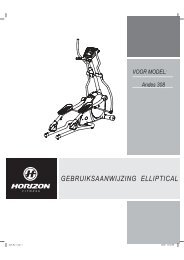
TARGET HEART RATE zONE CHART<br />
What is Target Heart Rate zone?<br />
Target Heart Rate Zone tells you the number of times per minute your heart needs to beat<br />
to achieve a desired workout effect. It is represented as a percentage of the maximum<br />
number of times your heart can beat per minute. Target Zone will vary for each individual,<br />
depending on age, current level of conditioning, and personal fitness goals. The American<br />
Heart Association recommends working-out at a Target Heart Rate Zone of between 60%<br />
and 75% of your maximum heart rate. A beginner will want to workout in the 60% range<br />
while a more experienced exerciser will want to workout in the 70-75% range. See chart<br />
for reference.<br />
EXAMPLE:<br />
For a 42-year-old user: Find age along the bottom of the chart (round to 40), follow age column up to the target zone bar. Results: 60% of<br />
maximum Heart Rate = 108 Beats Per Minute, 75% of maximum Heart Rate = 135 Beat Per Minute.<br />
ALWAYS CONSULT YOUR PHYSICIAN BEFORE BEGINNING AN EXERCISE PROGRAM.<br />
20 21<br />
100%<br />
75%<br />
60%<br />
BEATS PER MINUTE<br />
AGE<br />
150 146 143 139 135 131 128 124 120 116<br />
T A R G E T Z O N E<br />
120 117 114 111 108 105 102 99 97 93<br />
20 25 30 35 40 45 50 55 60 65
TIPS STRETCHING TIPS THE IMPORTANCE OF WARM UP & COOL DOWN<br />
STRETCH FIRST<br />
Before using your product, it is best to take a few minutes doing a few gentle stretching exercises. Stretching prior to exercise will improve<br />
flexibility and reduce chances of exercise related injury. Ease into each of these stretches with a slow gentle motion. Do not stretch to the point<br />
of pain. Make sure not to bounce while doing these stretches.<br />
1. STANDING CALF MUSCLE STRETCH<br />
Stand near a wall with the toes of tour left foot about 18” from the wall, and the right foot about 12” behind the other<br />
foot. Lean forward, pushing against the wall with your palms. Keep your heels flat and hold this position for a count of<br />
15 seconds. Make sure that you do not bounce while stretching. Repeat on the other side.<br />
2. STANDING QUADRICEPS STRETCH<br />
Using a wall to provide balance, grasp your left ankle with your left hand and hold your foot against the back of your<br />
thigh for 15 seconds. Repeat with your right ankle and hand.<br />
22. SITTING HAMSTRING & LOWER BACK MUSCLE STRETCH<br />
Sit on the floor with your legs together and straight out in front of you. Do not lock your knees. Extend your fingers<br />
towards your toes and hold for a count of 15 seconds. Make sure that you do not bounce while stretching. Sit upright<br />
again. Repeat one time.<br />
WARM UP<br />
Always perform 10-15 minutes of aerobic activity before begining your strength training session. This warm-up will limber your muscles and<br />
prepare them for more strenuous exercise. Make sure that you warm-up on your product at a slow pace. The warm up should gradually<br />
increase your heart rate into your heart rate training zone and increase core body temperature.<br />
COOL DOWN<br />
Never stop exercising suddenly! A cool-down period of 3-5 minutes allows your heart to readjust to the decreased demand. Your<br />
cool-down period should consist of repeating the stretching exercises listed above to loosen and relax your muscles.<br />
ACHIEVING YOUR FITNESS GOALS<br />
22 23<br />
TIPS<br />
An important step in developing a long term fitness program is to determine your goals. Is your primary goal for exercising to lose weight?<br />
Improve muscle tone and/or strength? Reduce stress? Knowing what your goals are will help you develop a more successful exercise<br />
program. Below are some common exercise goals:<br />
• Weight Loss - lower intensity, longer duration workouts<br />
• Improve Body Shape and Tone - interval workouts, alternate between hi and low intensities<br />
• Increased Energy Level - more frequent daily workouts<br />
• Improved Sports Performance - high intensity workouts<br />
If possible try to define your personal goals in precise, measurable terms, and then put your goals in writing. The more specific you<br />
can be, the easier it will be to track your progress. If your goals are long term, divide them up into monthly and weekly segments.<br />
Longer term goals can lose some of the immediate motivation benefits. Short term goals are easier to achieve.
TROUBLESHOOTING<br />
Your home gym is designed to be reliable and easy to use.<br />
However, if you experience a problem, please reference the<br />
troubleshooting guide listed below.<br />
PROBLEM: The cables feel rough and are noisy during use.<br />
SOLUTION: Verify the following:<br />
IS THERE ANY NOTICABLE DAMAGE TO THE CABLES?<br />
IF YES:<br />
• Contact customer tech support and replace the cable(s).<br />
IF NO:<br />
• Verify that all cables are secured into the pulleys.<br />
• Verify that the weight stack guiderods are lubricated.<br />
• Verify that there is no excessive slack in the cables.<br />
NOTE: If there is excessive slack adjust cable tension (see<br />
next page)<br />
PROBLEM: Weight selector pin cannot be inserted.<br />
SOLUTION: Verify the following:<br />
ARE THE HOLES ALLIGNED THROUGH THE WEIGHT<br />
PLATE AND BAYONETTE?<br />
IF YES:<br />
• Verify that the selector pin isn’t bent or damaged.<br />
IF NO:<br />
• Adjust threaded bolt on top plate so that the holes in the<br />
bayonette align with the weight plate.<br />
NOTE: Always maintain at least ½˝ of threaded bolt in<br />
bayonette.<br />
If the above troubleshooting section does not remedy the<br />
problem, discontinue use.<br />
PLEASE CALL CUSTOMER TECH SUPPORT AT THE<br />
NUMBER ON THE BACK PANEL.<br />
The following information may be asked of you when you call.<br />
Please have these items readily available:<br />
• Model Name<br />
• Serial Number<br />
• Date of Purchase (receipt or credit card statement)<br />
In order for Customer Tech Support to service your home gym<br />
they may need to ask detailed questions about the symptoms<br />
that are occurring. Some troubleshooting questions that may<br />
be asked are:<br />
• How long has this problem been occurring?<br />
• Does this problem occur with every use? With every user?<br />
• If you are hearing a noise, does it come from the front or the<br />
back? What kind of noise is it (thumping, grinding, squeaking,<br />
chirping etc.)?<br />
• Has the machine been lubricated and maintained per the<br />
maintenance schedule?<br />
Answering these and other questions will give the technicians<br />
the ability to send proper replacement parts and the service<br />
necessary to get you and your <strong>Horizon</strong> <strong>Fitness</strong> home gym<br />
functioning again!<br />
MAINTENANCE<br />
Cleanliness of your home gym and its operation environment will keep maintenance problems and service calls to a minimum. For this reason,<br />
we recommend that the following preventive maintenance schedule be followed.<br />
AFTER EACH USE (DAILY)<br />
• Wipe upholstery, handgrips, bars, and frame (if needed) with a mild cleaning solution.<br />
EVERY WEEK<br />
• Lubricate guide rods with a spray or gel silicone lubricant.• Inspect cable ends and cable insulation for damage.<br />
EVERY MONTH - IMPORTANT!<br />
• Inspect all frame bolts and tighton as needed.<br />
Please contact <strong>Horizon</strong> <strong>Fitness</strong> with questions about applying lubricant to your home gym.<br />
ADJUSTING CABLE TENSION<br />
Regularly check the cable tension of your home gym. If excesive slack exists adjust cable tension by moving one or both pulleys to<br />
the inner mounting position in the dual floating pulley bracket.<br />
INNER MOUNTING POSITIONS<br />
24 25
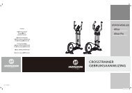
TORUS 4 EXPLODED VIEW TORUS 4 PARTS LIST<br />
E04<br />
E03<br />
T15<br />
AT1 Z06<br />
H13<br />
AH2<br />
J03<br />
T17<br />
T16<br />
T10<br />
Z06 Z05<br />
H12<br />
Z31<br />
G33<br />
G33<br />
G34<br />
G33<br />
G30<br />
G33<br />
AG2<br />
Z06<br />
Z05<br />
Z26<br />
AE1<br />
AT3<br />
Z05<br />
Z05<br />
J02<br />
H18<br />
J03 H13<br />
G34<br />
G43<br />
E03 E04<br />
T15<br />
G35<br />
Z05<br />
Z31<br />
Z32<br />
Z05<br />
Z02<br />
H29<br />
Z02<br />
H31<br />
G43<br />
G35<br />
Z06Z29 Z05<br />
T11<br />
H14<br />
Z17 Z31<br />
AT2<br />
T12<br />
J01<br />
H15<br />
H19<br />
Z11<br />
G37<br />
C19<br />
G30<br />
G30<br />
AG3<br />
G30<br />
AG1 G27<br />
Z03<br />
Z05<br />
Z04<br />
G35 C20<br />
AB1<br />
Z35<br />
Z28<br />
Z25<br />
Z05<br />
Z05<br />
G29<br />
Z06<br />
G34<br />
G33<br />
G34<br />
G30 G33<br />
G30<br />
AC1<br />
C13<br />
C12<br />
C19<br />
C14<br />
C19C18<br />
M07<br />
M06 C14 C13<br />
M08<br />
M07<br />
C14<br />
AM1<br />
C13<br />
C12<br />
C14<br />
M08<br />
C18<br />
Z06 Z05<br />
Z06<br />
B03Z05Z04<br />
Z04<br />
Z05<br />
B04<br />
G30<br />
Z06<br />
Z05<br />
Z26<br />
Z05<br />
F18 F15F16<br />
AN12<br />
F18 F15<br />
F17<br />
F17<br />
F16<br />
C12<br />
C13<br />
Z05<br />
Z06<br />
Z06<br />
Z05<br />
B04<br />
B03Z05Z04<br />
Z04<br />
Z05<br />
F17<br />
F18<br />
F17<br />
F07<br />
C20<br />
C13<br />
C19<br />
C12<br />
C13<br />
AB1<br />
F15 F17 F16<br />
G33<br />
G26<br />
G33<br />
G34<br />
Z12<br />
G28<br />
G21 AG4<br />
H19<br />
H15<br />
G21<br />
Z06Z29 Z05<br />
Z05<br />
Z31<br />
Z32<br />
Z11<br />
H16<br />
G34 Z20<br />
Z14<br />
Z20<br />
Z14<br />
Q07<br />
Z20<br />
Z20<br />
Q06<br />
F15<br />
F16<br />
F17 H17<br />
H15 H18<br />
Z14<br />
Q01<br />
Z20<br />
Z20<br />
F18<br />
H19<br />
H16 H17<br />
Z13<br />
H18<br />
H15 F16<br />
G53<br />
Z14<br />
Z20<br />
Z20<br />
Z14<br />
Q07<br />
H15<br />
AH1<br />
AF1<br />
F17<br />
Q02 Z20<br />
F18<br />
Q04(2)<br />
C17<br />
Z20(8)<br />
Z03<br />
Z20(8)<br />
G35<br />
G26<br />
Q04(4)<br />
Z14(8)<br />
G34<br />
Z09<br />
Z19<br />
Z33<br />
K03<br />
K07<br />
K16<br />
K05<br />
AK04<br />
Z10<br />
K17<br />
K12<br />
K15<br />
H26<br />
H32<br />
C20<br />
C19<br />
C20<br />
C19<br />
K10<br />
K20<br />
K08<br />
K14<br />
K01<br />
K09<br />
K02<br />
AF1<br />
F21<br />
H33<br />
H32<br />
F16<br />
Z09<br />
F21<br />
Z19<br />
Z10<br />
H26<br />
F15<br />
K11<br />
Q03(2)<br />
C22<br />
K11<br />
Z14(8)<br />
C22C14<br />
C20<br />
C19<br />
C20<br />
C19<br />
Z21<br />
C19<br />
G37<br />
G36<br />
NO. DESCRIPTION<br />
AB1 SCREW;SH;M10X1.5PX45L-12L;HS;ZN;P-T<br />
AE1 PULLDOWN GRIP SET-S400**DISC USE 092894<br />
AF1 PULLEY;SWIVEL ARM SET;<br />
AF2 FIX PLATE;PULLY;PAINTING;GM204<br />
AG1 FRONT DISASSEMBLY CON SET<br />
AG2 DISASSEMBLY CON SET;U;PAINTING;GM204<br />
AG3 DISASSEMBLY CON SET**DISC NOT STOCKING<br />
AG4 ADJ SET;SWIVEL ARM;PAINTING;GM204<br />
AH1 ADJUST SWIVEL ARM<br />
AH2 PEDAL ARM SET-S400<br />
AK4 ADJ MAST SET;WEIGHT PLATE;CR;GM204<br />
AM1 PEDAL SET;PAINTING;GM204<br />
AN12 BRACKET FLOATING PULLEY<br />
AT1 ADJ SET;SEAT;GM201-SXS 5.7<br />
AT2 SUPT SET;SEAT;PAINTING;GM204<br />
AT3 PAINTING;SEAT PAD ADJ SET;GM201<br />
AZ1 HARDWARE;GM204<br />
B03 REINFORCE;TUBE;PAINTING;990X300L;GM204<br />
C12 END COVER;ELLIPSE;GM03<br />
C13 PAD FRAME STABILIZER<br />
C14 SCREW;BH;M5X0.8PX10L;HS;ZN;<br />
C17 PULLEY;Φ90.2;MARKET;GM204<br />
C18 SCREW;SH;M10X1.5PX45L-12L;HS;ZN;P-T<br />
C19 WASHER;FLT;Φ10.2XΦ22X2.0T;WZN;<br />
C20 NUT;NLK;M10X1.5P;ZN;<br />
NO. DESCRIPTION<br />
C22 SCREW;HEX; ZN PLATE;M10X1.5PX60L;<br />
E03 CAP;GRIP;GM204<br />
F15 PULLEY;Φ90.2;MARKET;GM204<br />
F16 SCREW;SH;M10X1.5PX45L-12L;HS;ZN;P-T<br />
F17 WASHER;FLT;Φ10.2XΦ22X2.0T;WZN;<br />
F18 NUT;NLK;M10X1.5P;ZN;<br />
F21 CLAMP;E-SHAPED;E-19;CR;<br />
G21 PIN SET;SEMI-ASSY;GM204-KM<br />
G26 END COVER;ELLIPSE;GM03<br />
G27 DECAL;COVER;FRONT;ABS;GM204<br />
G28 DECAL;COVER;REAR;ABS;GM204<br />
G29 PULL PIN;ADJUSTMENT;SEAT;GM204<br />
G30 PULLEY;Φ90.2;MARKET;GM204<br />
G33 SCREW;SH;M10X1.5PX45L-12L;HS;ZN;P-T<br />
G34 WASHER;FLT;Φ10.2XΦ22X2.0T;WZN;<br />
G35 NUT;NLK;M10X1.5P;ZN;<br />
G36 SCREW;SH;M10X1.5PX95-20L;HS;ZN;P-T<br />
G53 STOP RUBBER RANGE OF MOTION<br />
H12 CAP;Φ50.8X2.0T MARKET;GM204<br />
H13 END CAP HANDLEBAR<br />
H14 AXLE;GM204<br />
H16 PULLEY;Φ90.2;MARKET;GM204<br />
H17 SCREW;SH;M10X1.5PX45L-12L;HS;ZN;P-T<br />
H18 WASHER;FLT;Φ10.2XΦ22X2.0T;WZN;<br />
H19 NUT;NLK;M10X1.5P;ZN;<br />
26 Z42<br />
27
NO. DESCRIPTION<br />
H26 END-CAP;Φ60;ABS;GM03<br />
H29 SCREW;SH;M10X1.5PX30L-12L;HS;P-T<br />
H31 STEEL ROPE;3;EXRTA-WORK;STEEL ROPE HEAD;<br />
H32 SCREW;BH;M12X1.75PX25L;HS;ZN;<br />
H33 WASHER;FLT;Φ13XΦ37X3.0T;CHM;<br />
J01 PAD SET**DISC ORDER INDIVIDUALLY<br />
J01 BACK PAD;CSG3;GM204<br />
J02 SEAT PAD;CSG3;GM204<br />
J03 LEG PAD;CSG3;GM204-SXS5.7<br />
K01 TOP WEIGHT PLATE<br />
K02 WEIGHT PLATE;10P;GM204<br />
K03 GUIDE RAIL;CR PLATE;GM204<br />
K05 LINK ROD;20#;GM204<br />
K07 CAP;ADJ TUBE;GM204<br />
K08 PIN;WEIGHT PLATE;Φ10X145L;GM204<br />
K09 SLEEVE;D;WEIGHT PLATE;GM204<br />
K10 STOPPER PIN;WEIGHT PLATE;GM204<br />
K11 SUPT BLOCK;WEIGHT PLATE;GM204<br />
K12 SLEEVE;D;WEIGHT PLATE;GM204<br />
K14 SLEEVE;WEIGHT;PLATE;GM204<br />
K15 SHIM;WEIGHT PLATE;GM204-KM<br />
K17 GUIDE ROD;SLEEVETUBE;GM204<br />
K20 WEIGHT PLATE;5 P;DIPPING;EXRTA-WORK;GM20<br />
K20 ELASTIC ROPE;GM300-KM<br />
M06 SCREW;SH;M8X1.25PX65L;HS;ZN;<br />
NO. DESCRIPTION<br />
M07 WASHER;FLT;Φ8.4XΦ15.5X1.6T;WZN;<br />
M08 NUT;NLK;M8X1.25P;ZN;<br />
Q01 COVER;PAINTING;GM204-KM<br />
Q02 COVER;L;PAINTING;**DISC USE 091474<br />
Q03 FIX PLATE;COVER;WELDING;GM204<br />
Q04 FIXING PLATE;U;GM204<br />
Q06 COVER;B;PAINTING;GM204-KM<br />
Q07 FIX PLATE;U;COVER;GM208-US<br />
Q07 FIX PLATE;B;COVER;PAINTING;GM204<br />
T10 STOPPER BLOCK;RUBBER;GM02<br />
T11 PULL PIN 35MM<br />
T12 CAP;SQUARE TUBE;FW162<br />
T15 END CAP 25X50X3<br />
T16 SCREW;SH;M10X1.5PX35L;HS;G4.8;ZN;<br />
T17 WASHER;FLT;Φ10.2XΦ22X2.0T;WZN;<br />
V01 WARNING STICKER;SEAT ADJ TUBE;GM204<br />
V02 WARNING STICKER;SWIVEL ARM;GM204<br />
V03 WARNING STICKER;PULL DOWN HANDLE;GM204<br />
V04 WARNING STICKER;BASE TUBE;GM204<br />
V05 WARNING STICKER;SHIELD;GM204<br />
V06 DECAL,WEIGHT PLATE;GM204<br />
V08 MODEL STICKER;GM204<br />
V09 STICKER<br />
V13 DECAL;SWIVEL ARM;1;GM204<br />
V14 DECAL;SWIVEL ARM;2;GM204<br />
NO. DESCRIPTION<br />
V17 ELASTIC ROPE;GM200<br />
V18 TRAINNING CARD;GM200<br />
V20 MAGNET SPARE SINGLE<br />
V21 INDICATION DECAL;LEFT;EP32<br />
V22 INDICATION DECAL;RIGHT;EP32<br />
X01 <strong>MANUAL</strong>;ASSEMBLY;GM204<br />
X02 <strong>MANUAL</strong>;ASSEMBLY GUIDE;GERMANY;GM204<br />
Z02 SCREW;SH;M5X0.8PX10L;HS;G4.8;ZN;<br />
Z02 SCREW;SH;M10X1.5PX75L;HS;G4.8;ZN;<br />
Z03 SCREW;SH;M10X1.5PX60L;HS;G4.8;ZN;<br />
Z04 SCREW;SH;M10X1.5PX65L;HS;G4.8;ZN;<br />
Z05 WASHER;FLT;Φ10.2XΦ22X2.0T;WZN;<br />
Z06 NUT;NLK;M10X1.5P;ZN;<br />
Z09 WASHER;FLT;Φ8.2XΦ15.0X1.2T;WZN;<br />
Z10 NUT;NLK;M8X1.25P;ZN;<br />
Z11 SCREW;SH;M10X1.5PX35L-12L;HS;P-T<br />
Z12 SCREW;BH;M5X0.8PX15L;SM;PH;45#;ZN;POT<br />
Z13 SCREW;SH;M8X1.25PX20L;HS;G4.8;ZN;<br />
Z14 WASHER;FLT;Φ5.2X10X1.5T;WZN;<br />
Z17 SCREW;RND;M10X1.5PX85L-20L;HS;G4.8;WZN;P<br />
Z19 SCREW;SH;M8X1.25PX95L;HS;G4.8;ZN;<br />
Z20 SCREW;SH;M5X0.8PX10L;HS;G4.8;ZN;<br />
Z21 SCREW;SH;M8X1.25PX15L;HS;ZN;<br />
Z25 STEEL CABLE;EXRTA-WORK;STEEL CABLE HEAD;<br />
Z26 SCREW;SH;M10X1.5PX25L;HS;ZN;<br />
NO. DESCRIPTION<br />
Z28 STEEL ROPE;4;EXRTA-WORK;STEEL ROPE HEAD;<br />
Z29 FIX BASE;U TYPE;CSG3;GM200<br />
Z31 SPRING SNAP;KARABINER;7.5;CR;-SXS5.7<br />
Z33 SCREW;RND;M8X1.25PX45L;HS;G4.8;WZN<br />
Z35 STEEL ROPE ;C;EXRTA-WORK;STEEL ROPE HEAD<br />
Z42 ANKLE STRAP-STRENGTH MODELS<br />
28 29
D: Entsorgungshinweis<br />
Vision <strong>Fitness</strong> /<strong>Horizon</strong> <strong>Fitness</strong>/TEMPO <strong>Fitness</strong> /TREO <strong>Fitness</strong> - Produkte sind recyclebar. Führen Sie das Gerät<br />
am Ende der Nutzungsdauer einer sachgerechten Entsorgung zu (örtliche Sammelstelle).<br />
GB: Waste Disposal<br />
Vision <strong>Fitness</strong> /<strong>Horizon</strong> <strong>Fitness</strong>/TEMPO <strong>Fitness</strong> /TREO <strong>Fitness</strong> products are recyclable. At the end if its useful life<br />
please dispose of this article correctly and safely (local refuse sites).<br />
F: Remarque relative à la gestion des dèchets<br />
Les produits Vision <strong>Fitness</strong> /<strong>Horizon</strong> <strong>Fitness</strong>/TEMPO <strong>Fitness</strong> /TREO <strong>Fitness</strong> sont recyclables. A la fin sa durrèe<br />
d`utilisation, remettez I´appareil à un centre de gestion de dèchets correct (collecte locale).<br />
NL: Verwijderingsaanwijzing<br />
Vision <strong>Fitness</strong> /<strong>Horizon</strong> <strong>Fitness</strong>/TEMPO <strong>Fitness</strong> /TREO <strong>Fitness</strong> producten zijn recycleerbaar. Breng het apparaat<br />
aan het einde van de gebruiksduur naar een op recycling gespecialiseerd bedrijf (plaatselijk verzamelpunt).<br />
E: Informaciones para la evacuaciòn<br />
Los productos de Vision <strong>Fitness</strong> /<strong>Horizon</strong> <strong>Fitness</strong>/TEMPO <strong>Fitness</strong> /TREO <strong>Fitness</strong> son riciclables. Cuando se<br />
termina la vida ùtil de un aparato o una màquina, entrèguelos an una impresa local de eleiminaciòn de residuos<br />
para su reciclaje.<br />
I: Indicazione sullo smaltimento<br />
I prodotti Vision <strong>Fitness</strong> /<strong>Horizon</strong> <strong>Fitness</strong>/TEMPO <strong>Fitness</strong> /TREO <strong>Fitness</strong> sono reciclabill. Quando I`apparecchio<br />
non servirà più, portatelo in un apposito punto di raccolta della Vostra città (Punti di raccolta comunall).<br />
PL: Wskazòwka dotyczàca usuwania odpadòw.<br />
Producty firmy Vision <strong>Fitness</strong> /<strong>Horizon</strong> <strong>Fitness</strong>/TEMPO <strong>Fitness</strong> /TREO <strong>Fitness</strong> podlegajà recyklingowi. Pod koniec<br />
okresu o`ywalnoÈcl pros`z oddac urzàdzenie do wlaÈciwego punkto usuwania odpadòw (lokalny punkt zbiorczy).
<strong>HOME</strong> <strong>GYM</strong> OWNER’S <strong>MANUAL</strong><br />
Torus 4 Owner’s Manual 0605’12 Rev. 1.2 © 2012 <strong>Horizon</strong> <strong>Fitness</strong>