EMCO WinNC SINUMERIK 810D/840D Frezen Softwarebeschrijving
EMCO WinNC SINUMERIK 810D/840D Frezen Softwarebeschrijving
EMCO WinNC SINUMERIK 810D/840D Frezen Softwarebeschrijving

You also want an ePaper? Increase the reach of your titles
YUMPU automatically turns print PDFs into web optimized ePapers that Google loves.
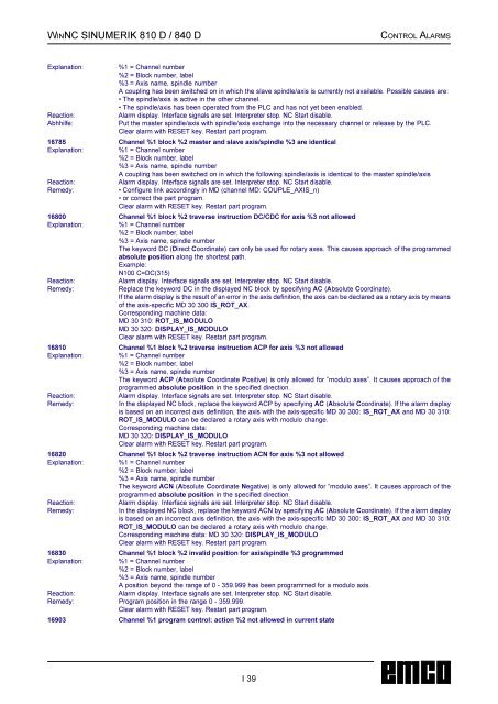
WINNC <strong>SINUMERIK</strong> 810 D / 840 D CONTROL ALARMS<br />
Explanation: %1 = Channel number<br />
%2 = Block number, label<br />
%3 = Axis name, spindle number<br />
A coupling has been switched on in which the slave spindle/axis is currently not available. Possible causes are:<br />
• The spindle/axis is active in the other channel.<br />
• The spindle/axis has been operated from the PLC and has not yet been enabled.<br />
Reaction: Alarm display. Interface signals are set. Interpreter stop. NC Start disable.<br />
Abhhilfe: Put the master spindle/axis with spindle/axis exchange into the necessary channel or release by the PLC.<br />
Clear alarm with RESET key. Restart part program.<br />
16785 Channel %1 block %2 master and slave axis/spindle %3 are identical<br />
Explanation: %1 = Channel number<br />
%2 = Block number, label<br />
%3 = Axis name, spindle number<br />
A coupling has been switched on in which the following spindle/axis is identical to the master spindle/axis<br />
Reaction: Alarm display. Interface signals are set. Interpreter stop. NC Start disable.<br />
Remedy: • Configure link accordingly in MD (channel MD: COUPLE_AXIS_n)<br />
• or correct the part program.<br />
Clear alarm with RESET key. Restart part program.<br />
16800 Channel %1 block %2 traverse instruction DC/CDC for axis %3 not allowed<br />
Explanation: %1 = Channel number<br />
%2 = Block number, label<br />
%3 = Axis name, spindle number<br />
The keyword DC (Direct Coordinate) can only be used for rotary axes. This causes approach of the programmed<br />
absolute position along the shortest path.<br />
Example:<br />
N100 C=DC(315)<br />
Reaction: Alarm display. Interface signals are set. Interpreter stop. NC Start disable.<br />
Remedy: Replace the keyword DC in the displayed NC block by specifying AC (Absolute Coordinate).<br />
If the alarm display is the result of an error in the axis definition, the axis can be declared as a rotary axis by means<br />
of the axis-specific MD 30 300 IS_ROT_AX.<br />
Corresponding machine data:<br />
MD 30 310: ROT_IS_MODULO<br />
MD 30 320: DISPLAY_IS_MODULO<br />
Clear alarm with RESET key. Restart part program.<br />
16810 Channel %1 block %2 traverse instruction ACP for axis %3 not allowed<br />
Explanation: %1 = Channel number<br />
%2 = Block number, label<br />
%3 = Axis name, spindle number<br />
The keyword ACP (Absolute Coordinate Positive) is only allowed for ”modulo axes”. It causes approach of the<br />
programmed absolute position in the specified direction.<br />
Reaction: Alarm display. Interface signals are set. Interpreter stop. NC Start disable.<br />
Remedy: In the displayed NC block, replace the keyword ACP by specifying AC (Absolute Coordinate). If the alarm display<br />
is based on an incorrect axis definition, the axis with the axis-specific MD 30 300: IS_ROT_AX and MD 30 310:<br />
ROT_IS_MODULO can be declared a rotary axis with modulo change.<br />
Corresponding machine data:<br />
MD 30 320: DISPLAY_IS_MODULO<br />
Clear alarm with RESET key. Restart part program.<br />
16820 Channel %1 block %2 traverse instruction ACN for axis %3 not allowed<br />
Explanation: %1 = Channel number<br />
%2 = Block number, label<br />
%3 = Axis name, spindle number<br />
The keyword ACN (Absolute Coordinate Negative) is only allowed for ”modulo axes”. It causes approach of the<br />
programmed absolute position in the specified direction.<br />
Reaction: Alarm display. Interface signals are set. Interpreter stop. NC Start disable.<br />
Remedy: In the displayed NC block, replace the keyword ACN by specifying AC (Absolute Coordinate). If the alarm display<br />
is based on an incorrect axis definition, the axis with the axis-specific MD 30 300: IS_ROT_AX and MD 30 310:<br />
ROT_IS_MODULO can be declared a rotary axis with modulo change.<br />
Corresponding machine data: MD 30 320: DISPLAY_IS_MODULO<br />
Clear alarm with RESET key. Restart part program.<br />
16830 Channel %1 block %2 invalid position for axis/spindle %3 programmed<br />
Explanation: %1 = Channel number<br />
%2 = Block number, label<br />
%3 = Axis name, spindle number<br />
A position beyond the range of 0 - 359.999 has been programmed for a modulo axis.<br />
Reaction: Alarm display. Interface signals are set. Interpreter stop. NC Start disable.<br />
Remedy: Program position in the range 0 - 359.999.<br />
Clear alarm with RESET key. Restart part program.<br />
16903Channel %1 program control: action %2 not allowed in current state<br />
I 39