EMCO WinNC SINUMERIK 810D/840D Frezen Softwarebeschrijving
EMCO WinNC SINUMERIK 810D/840D Frezen Softwarebeschrijving
EMCO WinNC SINUMERIK 810D/840D Frezen Softwarebeschrijving
Create successful ePaper yourself
Turn your PDF publications into a flip-book with our unique Google optimized e-Paper software.
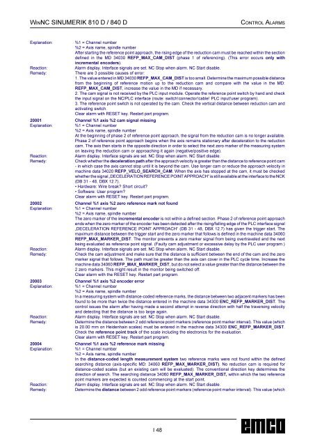
WINNC <strong>SINUMERIK</strong> 810 D / 840 D CONTROL ALARMS<br />
Explanation: %1 = Channel number<br />
%2 = Axis name, spindle number<br />
After starting the reference point approach, the rising edge of the reduction cam must be reached within the section<br />
defined in the MD 34030 REFP_MAX_CAM_DIST (phase 1 of referencing). (This error occurs only with<br />
incremental encoders).<br />
Reaction: Alarm display. Interface signals are set. NC Stop when alarm. NC Start disable.<br />
Remedy: There are 3 possible causes of error:<br />
1. The value entered in MD 34030 REFP_MAX_CAM_DIST is too small. Determine the maximum possible distance<br />
from the beginning of reference motion up to the reduction cam and compare with the value in the MD:<br />
REFP_MAX_CAM_DIST, increase the value in the MD if necessary.<br />
2. The cam signal is not received by the PLC input module. Operate the reference point switch by hand and check<br />
the input signal on the NC/PLC interface (route: switch!connector!cable! PLC input!user program).<br />
3. The reference point switch is not operated by the cam. Check the vertical distance between reduction cam and<br />
activating switch.<br />
Clear alarm with RESET key. Restart part program.<br />
20001 Channel %1 axis %2 cam signal missing<br />
Explanation: %1 = Channel number<br />
%2 = Axis name, spindle number<br />
At the beginning of phase 2 of reference point approach, the signal from the reduction cam is no longer available.<br />
Phase 2 of reference point approach begins when the axis remains stationary after deceleration to the reduction<br />
cam. The axis then starts in the opposite direction in order to select the next zero marker of the measuring system<br />
on leaving the reduction cam or approaching it again (negative/positive edge).<br />
Reaction: Alarm display. Interface signals are set. NC Stop when alarm. NC Start disable.<br />
Remedy: Check whether the deceleration path after the approach velocity is greater than the distance to reference point cam<br />
- in which case the axis cannot stop until it is beyond the cam. Use longer cam or reduce the approach velocity in<br />
machine data 34020 REFP_VELO_SEARCH_CAM. When the axis has stopped at the cam, it must be checked<br />
whether the signal „DECELERATION REFERENCE POINT APPROACH“ is still available at the interface to the NCK<br />
(DB 31 - 48, DBX 12.7).<br />
• Hardware: Wire break? Short circuit?<br />
• Software: User program?<br />
Clear alarm with RESET key. Restart part program.<br />
20002 Channel %1 axis %2 zero reference mark not found<br />
Explanation: %1 = Channel number<br />
%2 = Axis name, spindle number<br />
The zero marker of the incremental encoder is not within a defined section. Phase 2 of reference point approach<br />
ends when the zero marker of the encoder has been detected after the rising/falling edge of the PLC interface signal<br />
„DECELERATION REFERENCE POINT APPROACH“ (DB 31 - 48, DBX 12.7) has given the trigger start. The<br />
maximum distance between the trigger start and the zero marker that follows is defined in the machine data 34060<br />
REFP_MAX_MARKER_DIST. The monitor prevents a zero marker signal from being overtraveled and the next<br />
being evaluated as reference point signal. (Faulty cam adjustment or excessive delay by the PLC user program.)<br />
Reaction: Alarm display. Interface signals are set. NC Stop when alarm. NC Start disable.<br />
Remedy: Check the cam adjustment and make sure that the distance is sufficient between the end of the cam and the zero<br />
marker signal that follows. The path must be greater than the axis can cover in the PLC cycle time. Increase the<br />
machine data 34060 REFP_MAX_MARKER_DIST, but do not select a value greater than the distance between the<br />
2 zero markers. This might result in the monitor being switched off.<br />
Clear alarm with the RESET key. Restart part program.<br />
20003Channel %1 axis %2 encoder error<br />
Explanation: %1 = Channel number<br />
%2 = Axis name, spindle number<br />
In a measuring system with distance-coded reference marks, the distance between two adjacent markers has been<br />
found to be more than twice the distance entered in the machine data 34300 ENC_REFP_MARKER_DIST. The<br />
control issues the alarm after having made a second attempt in reverse direction with half the traversing velocity<br />
and detecting that the distance is too large again.<br />
Reaction: Alarm display. Interface signals are set. NC Stop when alarm. NC Start disable.<br />
Remedy: Determine the distance between 2 odd reference point markers (reference point marker interval). This value (which<br />
is 20.00 mm on Heidenhain scales) must be entered in the machine data 34300 ENC_REFP_MARKER_DIST.<br />
Check the reference point track of the scale including the electronics for the evaluation.<br />
Clear alarm with RESET key. Restart part program.<br />
20004 Channel %1 axis %2 reference mark missing<br />
Explanation: %1 = Channel number<br />
%2 = Axis name, spindle number<br />
In the distance-coded length measurement system two reference marks were not found within the defined<br />
searching distance (axis-specific MD: 34060 REFP_MAX_MARKER_DIST). No reduction cam is required for<br />
distance-coded scales (but an existing cam will be evaluated). The conventional direction key determines the<br />
direction of search. The searching distance 34060 REFP_MAX_MARKER_DIST, within which the two reference<br />
point markers are expected is counted commencing at the start point.<br />
Reaction: Alarm display. Interface signals are set. NC Stop when alarm. NC Start disable.<br />
Remedy: Determine the distance between 2 odd reference point markers (reference point marker interval). This value (which<br />
I 48


