Kth - sdr - kit
Kth - sdr - kit
Kth - sdr - kit

Create successful ePaper yourself
Turn your PDF publications into a flip-book with our unique Google optimized e-Paper software.
6/13/2010 KTH - SDR - KIT Page 3<br />
________________________________________________________________________________<br />
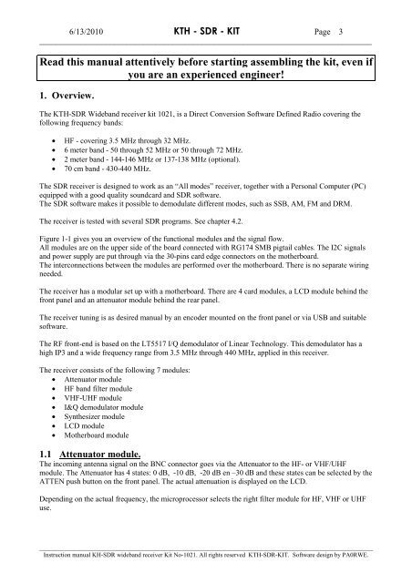
Read this manual attentively before starting assembling the <strong>kit</strong>, even if<br />
you are an experienced engineer!<br />
1. Overview.<br />
The KTH-SDR Wideband receiver <strong>kit</strong> 1021, is a Direct Conversion Software Defined Radio covering the<br />
following frequency bands:<br />
• HF - covering 3.5 MHz through 32 MHz.<br />
• 6 meter band - 50 through 52 MHz or 50 through 72 MHz.<br />
• 2 meter band - 144-146 MHz or 137-138 MHz (optional).<br />
• 70 cm band - 430-440 MHz.<br />
The SDR receiver is designed to work as an “All modes” receiver, together with a Personal Computer (PC)<br />
equipped with a good quality soundcard and SDR software.<br />
The SDR software makes it possible to demodulate different modes, such as SSB, AM, FM and DRM.<br />
The receiver is tested with several SDR programs. See chapter 4.2.<br />
Figure 1-1 gives you an overview of the functional modules and the signal flow.<br />
All modules are on the upper side of the board connected with RG174 SMB pigtail cables. The I2C signals<br />
and power supply are put through via the 30-pins card edge connectors on the motherboard.<br />
The interconnections between the modules are performed over the motherboard. There is no separate wiring<br />
needed.<br />
The receiver has a modular set up with a motherboard. There are 4 card modules, a LCD module behind the<br />
front panel and an attenuator module behind the rear panel.<br />
The receiver tuning is as desired manual by an encoder mounted on the front panel or via USB and suitable<br />
software.<br />
The RF front-end is based on the LT5517 I/Q demodulator of Linear Technology. This demodulator has a<br />
high IP3 and a wide frequency range from 3.5 MHz through 440 MHz, applied in this receiver.<br />
The receiver consists of the following 7 modules:<br />
• Attenuator module<br />
• HF band filter module<br />
• VHF-UHF module<br />
• I&Q demodulator module<br />
• Synthesizer module<br />
• LCD module<br />
• Motherboard module<br />
1.1 Attenuator module.<br />
The incoming antenna signal on the BNC connector goes via the Attenuator to the HF- or VHF/UHF<br />
module. The Attenuator has 4 states: 0 dB, -10 dB, -20 dB en –30 dB and these states can be selected by the<br />
ATTEN push button on the front panel. The actual attenuation is displayed on the LCD.<br />
Depending on the actual frequency, the microprocessor selects the right filter module for HF, VHF or UHF<br />
use.<br />
___________________________________________________________________________________________________________<br />
Instruction manual KH-SDR wideband receiver Kit No-1021. All rights reserved KTH-SDR-KIT. Software design by PA0RWE.