Kth - sdr - kit
Kth - sdr - kit
Kth - sdr - kit

You also want an ePaper? Increase the reach of your titles
YUMPU automatically turns print PDFs into web optimized ePapers that Google loves.
KTH - SDR - KIT<br />
KTH – SDR – RECEIVER KIT MANUAL<br />
1021
6/13/2010 KTH - SDR - KIT Page 1<br />
________________________________________________________________________________<br />
Version table<br />
Assembly Manual<br />
KH-SDR Wideband Receiver Kit No-1021<br />
Version: 2.1<br />
Date: 26-01-2010<br />
Auteur: J.v.Scheindelen PE1KTH<br />
R.W. Engberts PA0RWE<br />
Version Date Reason By<br />
1.0 26-01-2010 First issue RWE<br />
1.1 03-02-2010 Added LT5517 test and solder info and new picture IQ Board RWE<br />
2.0 20-03-2010 New picture of Synthesizer module, R4, R5 LCD module<br />
changed.<br />
Changes are made due to found errors and comments.<br />
Added Chapter 2.9 Testing the SDR.<br />
Added Chapter 6.3 Using PowerSDR and Rocky.<br />
50-70 MHz filter modification added.<br />
RWE<br />
2.1 13-06-2010 Changes due to the new firmware version 5.0 RWE<br />
All rights reserved by KTH-SDR-KIT. No part of this manual may be reproduced, stored in a database or<br />
retrieval system, or published, in any form or in any way, electronically, mechanically, by print, photo-print,<br />
microfilm or any other means without prior written permission from the publisher.<br />
The auteur have used their best efforts in ensuring the correctness of the information contained in this<br />
manual. They do not assume, and hereby disclaim, any liability to any party for any loss or damage caused<br />
by errors or omissions in this manual, whether such errors or omissions result from negligence, accident or<br />
any other cause.<br />
___________________________________________________________________________________________________________<br />
Instruction manual KH-SDR wideband receiver Kit No-1021. All rights reserved KTH-SDR-KIT. Software design by PA0RWE.
6/13/2010 KTH - SDR - KIT Page 2<br />
________________________________________________________________________________<br />
Table of Contents<br />
1. Overview. ....................................................................................................................................3<br />
1.1 Attenuator module. ..............................................................................................................3<br />
1.2 HF filter module...................................................................................................................4<br />
1.3 VHF-UHF module. ..............................................................................................................4<br />
1.4 I&Q demodulator module. ...................................................................................................4<br />
1.5 Synthesizer module..............................................................................................................4<br />
1.6 LCD moduul. .......................................................................................................................5<br />
1.7 Motherboard module............................................................................................................5<br />
2 Assembling and installing the modules....................................................................................6<br />
2.1 Assembling the enclosure (if applicable).............................................................................6<br />
2.2 Assembling and testing the Motherboard ............................................................................8<br />
2.3 Assembling and testing the Synthesizer module. ..............................................................11<br />
2.4 Assembling and testing the LCD module. .........................................................................18<br />
2.5 Assembling and testing the I & Q demodulator.................................................................24<br />
2.6 Assembling and testing the HF filter module ....................................................................30<br />
2.7 Assembling and testing the VHF-UHF module.................................................................39<br />
2.8 Assembling and testing the Attenuator Module.................................................................43<br />
2.9 Testing the SDR receiver ...................................................................................................48<br />
2.9.1 Power consumption....................................................................................................48<br />
3 KTH-SDR Software installation.............................................................................................49<br />
3.1 Introduction........................................................................................................................49<br />
3.2 Installation USB drivers.....................................................................................................49<br />
3.3 Installation V-USB driver ..................................................................................................49<br />
3.4 Calibrating the Si570 .........................................................................................................52<br />
3.5 How to Upgrade the KTH-SDR Firmware ........................................................................52<br />
3.6 Installation of the Microchip USB driver ..........................................................................53<br />
3.7 Problem Solving.................................................................................................................55<br />
3.7.1 No USB connection ...................................................................................................55<br />
3.7.2 PIC refuses to go into Bootload mode .......................................................................55<br />
3.7.3 Problems with installing a driver. ..............................................................................55<br />
4 Specifications............................................................................................................................57<br />
4.1 Measuring results ...............................................................................................................57<br />
4.2 Tested SDR software .........................................................................................................57<br />
5 Adjusting the KTH-SDR .........................................................................................................58<br />
5.1 Adjusting procedure UHF Helical bandfilter.....................................................................58<br />
5.2 Adjusting the 140-146 of 137-138 MHz bandpasfilter.....................................................58<br />
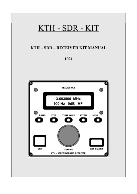
6 Operating Instructions ............................................................................................................59<br />
6.1 Manually controlled receiver .............................................................................................59<br />
6.2 Use the receiver as ‘slave’. ................................................................................................59<br />
6.3 Using of PowerSDR and Rocky ........................................................................................59<br />
6.3.1 USB / Si570 settings for PowerSDR .........................................................................59<br />
6.3.2 USB / Si570 Settings for Rocky 3.6 ..........................................................................61<br />
7 Soldering Technique and Tools ..............................................................................................63<br />
7.1 Tools needed for SMD soldering.......................................................................................63<br />
7.2 Soldering the QFN LT5517. .............................................................................................64<br />
8 Modifications............................................................................................................................67<br />
8.1 Extention of the 50 MHz filter to 70 MHz (IK0SMG)......................................................67<br />
9 Pictures......................................................................................................................................68<br />
___________________________________________________________________________________________________________<br />
Instruction manual KH-SDR wideband receiver Kit No-1021. All rights reserved KTH-SDR-KIT. Software design by PA0RWE.
6/13/2010 KTH - SDR - KIT Page 3<br />
________________________________________________________________________________<br />
Read this manual attentively before starting assembling the <strong>kit</strong>, even if<br />
you are an experienced engineer!<br />
1. Overview.<br />
The KTH-SDR Wideband receiver <strong>kit</strong> 1021, is a Direct Conversion Software Defined Radio covering the<br />
following frequency bands:<br />
• HF - covering 3.5 MHz through 32 MHz.<br />
• 6 meter band - 50 through 52 MHz or 50 through 72 MHz.<br />
• 2 meter band - 144-146 MHz or 137-138 MHz (optional).<br />
• 70 cm band - 430-440 MHz.<br />
The SDR receiver is designed to work as an “All modes” receiver, together with a Personal Computer (PC)<br />
equipped with a good quality soundcard and SDR software.<br />
The SDR software makes it possible to demodulate different modes, such as SSB, AM, FM and DRM.<br />
The receiver is tested with several SDR programs. See chapter 4.2.<br />
Figure 1-1 gives you an overview of the functional modules and the signal flow.<br />
All modules are on the upper side of the board connected with RG174 SMB pigtail cables. The I2C signals<br />
and power supply are put through via the 30-pins card edge connectors on the motherboard.<br />
The interconnections between the modules are performed over the motherboard. There is no separate wiring<br />
needed.<br />
The receiver has a modular set up with a motherboard. There are 4 card modules, a LCD module behind the<br />
front panel and an attenuator module behind the rear panel.<br />
The receiver tuning is as desired manual by an encoder mounted on the front panel or via USB and suitable<br />
software.<br />
The RF front-end is based on the LT5517 I/Q demodulator of Linear Technology. This demodulator has a<br />
high IP3 and a wide frequency range from 3.5 MHz through 440 MHz, applied in this receiver.<br />
The receiver consists of the following 7 modules:<br />
• Attenuator module<br />
• HF band filter module<br />
• VHF-UHF module<br />
• I&Q demodulator module<br />
• Synthesizer module<br />
• LCD module<br />
• Motherboard module<br />
1.1 Attenuator module.<br />
The incoming antenna signal on the BNC connector goes via the Attenuator to the HF- or VHF/UHF<br />
module. The Attenuator has 4 states: 0 dB, -10 dB, -20 dB en –30 dB and these states can be selected by the<br />
ATTEN push button on the front panel. The actual attenuation is displayed on the LCD.<br />
Depending on the actual frequency, the microprocessor selects the right filter module for HF, VHF or UHF<br />
use.<br />
___________________________________________________________________________________________________________<br />
Instruction manual KH-SDR wideband receiver Kit No-1021. All rights reserved KTH-SDR-KIT. Software design by PA0RWE.
6/13/2010 KTH - SDR - KIT Page 4<br />
________________________________________________________________________________<br />
1.2 HF filter module.<br />
The HF module consists of 7 half octave filters with a frequency range of 3.5 trough 32 MHz and one VHF<br />
filter for the 6-meter band (50-52 MHz). Switching of the filter sections is accomplished by PIN-diodes and<br />
controlled by I2C and the PIC controller, depending of the selected frequency. Optional a MAV-11 gainblock<br />
amplifier can be installed on the HF module to increase the sensitivity of the receiver.<br />
An addition for 70 MHz is available.<br />
1.3 VHF-UHF module.<br />
The VHF-UHF module is equipped with two filters: a 70 cm (430-440 MHz) Helical filter and a 2 meter<br />
(144-146 MHz) band filter. It is also possible to re-adjust the 2 meter band filter to the Weather satellite APT<br />
band (136-138 MHz).<br />
1.4 I&Q demodulator module.<br />
The LT5517 Quadrature demodulator is taking care of the direct conversion of the antenna signal to a I/Q<br />
baseband signal which will be connected to the stereo input of the soundcard. The soundcard bandwidth<br />
depends of the selected sampling frequency and the internal lowpassfilter of the card being used.<br />
The I en Q signals are, pre-amplified, available by means of 2 RCA connectors behind the rear panel.<br />
Figure 1-1 Overview of the modules.<br />
1.5 Synthesizer module.<br />
The Synthesizer module takes care of the frequency generation and the overall control of the receiver. The<br />
used controller is a PIC 18F2550 microcontroller and ready programmed for this application. Frequency<br />
generation is done by a Si570BBB LVDS programmable x-tal oscillator designed by Silicon Labs. The<br />
Si570 is controlled by I2C to set this device to the selected frequency.<br />
Because the LT5517 Quadrature demodulator needs a LO signal of twice the receiving frequency, the Si570<br />
generates a frequency two times the receiving frequency. The frequency displayed on the LCD is half the<br />
___________________________________________________________________________________________________________<br />
Instruction manual KH-SDR wideband receiver Kit No-1021. All rights reserved KTH-SDR-KIT. Software design by PA0RWE.
6/13/2010 KTH - SDR - KIT Page 5<br />
________________________________________________________________________________<br />
Si570 output frequency. There is no IF correction because of different IF frequencies applied in the various<br />
SDR software.<br />
The PIC microcontroller generates the I2C signals for controlling the modules. These signals are transferred<br />
via the motherboard en CON4 and CON9 connectors. Frequency control is performed by reading the 24ppr<br />
encoder or by commands via the USB port.<br />
Several ports of the microcontroller are used to read the push buttons on the front panel and for switching the<br />
HF, VHF and UHF band filters and power supply for these modules.<br />
Keypad use via I2C is optional and not yet implemented.<br />
1.6 LCD moduul.<br />
The LCD module PCB is mounted behind the front panel and on this PCB the LCD module and the function<br />
push buttons are mounted. Next to the push buttons, pull-up resistors are installed. They are useful when the<br />
R17 resistor array is not used.<br />
The I2C address of the LCD module is set by 3 jumpers, J1=0, J2=0 and J3=1.<br />
1.7 Motherboard module.<br />
The Motherboard module consists of an EURO card size board which fits precisely into the enclosure.<br />
Access to the USB and RCA connectors is via the front- and rear panel.<br />
The modules fit in the 30-pole card-edge connectors on the motherboard to prevent separate wiring. The<br />
LCD- and Attenuator module and also the encoder is connected to the motherboard by flat cable.<br />
It is up to the user which filter module (HF and/or VHF-UHF) should be used. It is also possible to design a<br />
filter (or other) module for a specific application to make this SDR <strong>kit</strong> very flexible.<br />
___________________________________________________________________________________________________________<br />
Instruction manual KH-SDR wideband receiver Kit No-1021. All rights reserved KTH-SDR-KIT. Software design by PA0RWE.
6/13/2010 KTH - SDR - KIT Page 6<br />
________________________________________________________________________________<br />
2 Assembling and installing the modules.<br />
The receiver consists of 7 modules and an enclosure (optional). By assembling the modules in a logical way,<br />
it is possible to test every module on its own placed in the motherboard connector. In this way you can<br />
simply check the different voltages from the voltage regulators before start mounting the delicate parts.<br />
Assembly steps:<br />
1. Assembling the enclosure<br />
2. Assembling and testing the Motherboard<br />
3. Assembling and testing the Synthesizer board<br />
4. Assembling and testing the LCD board<br />
5. Assembling and testing the I/Q demodulator board<br />
6. Assembling and testing the HF Filter board.<br />
7. Assembling and testing the VHF-UHF filter board<br />
8. Assembling and testing the Attenuator board<br />
Note: Read first before you start soldering, the recommendations in chapter 7.<br />
2.1 Assembling the enclosure (if applicable)<br />
Tip: Before soldering parts on the Motherboard, it is recommended to use the Motherboard PCB as<br />
a form for drilling the 4 x 3 mm holes in the lower part of the Enclosure.<br />
The Enclosure consists of two half aluminum shells and a front- and rear panel. On the lower shell the<br />
Motherboard is mounted on 4, 10 mm synthetic spacers. The 10 mm height fits with the holes in the front-<br />
and rear panel.<br />
In the panels are the required holes drilled and milled for the LCD board, Attenuator board, connectors,<br />
pushbuttons and encoder. On both panels are placards to give the radio a professional look.<br />
Put the Motherboard in the middle of the lower shell in a way that on both ends there will be 2,5 mm space.<br />
Mark the 4 holes on the shell and drill the holes with a 3.2 mm drill. The holes should be exactly between<br />
two ripples.<br />
After you have assembled en tested the Motherboard, you can mount it on 10 mm spacers with 4 M3-20<br />
screws. Don’t forget to mount the 4 stuts below the lower shell! See figure 2.1-1.<br />
___________________________________________________________________________________________________________<br />
Instruction manual KH-SDR wideband receiver Kit No-1021. All rights reserved KTH-SDR-KIT. Software design by PA0RWE.
6/13/2010 KTH - SDR - KIT Page 7<br />
________________________________________________________________________________<br />
Figure 2.1-1<br />
___________________________________________________________________________________________________________<br />
Instruction manual KH-SDR wideband receiver Kit No-1021. All rights reserved KTH-SDR-KIT. Software design by PA0RWE.
6/13/2010 KTH - SDR - KIT Page 8<br />
________________________________________________________________________________<br />
2.2 Assembling and testing the Motherboard<br />
Tip: Before soldering parts on the Motherboard, it is recommended to use the Motherboard PCB<br />
as a form for drilling the 4 x 3 mm holes in the lower part of the Enclosure.<br />
On figure 2.2-1 you can see the parts that should be soldered on the Motherboard. To reduce the heat in the<br />
Synthesizer module, the 12Volt supply voltage is lowered by a voltage regulator VR1 to about 8.5 Volt. The<br />
regulator is mounted at the bottom of the Motherboard. The zener-diode D1 raises the output from the 5V<br />
regulator to 8.5 Volt.<br />
Figure 2.2-1 Motherboard schematic with components.<br />
First solder the SMD parts at the bottom of the board. Check if the code stamp on VR1 is N06B. Use a<br />
mounting device for the PCB or mount 4 M3-20 screws in the 4 holes to use it as ‘table legs’. Solder the<br />
parts and connectors on the upper side of the board.<br />
See figure 2.2-2 and 2.2-3 for details.<br />
Check that the 10-pole box header connectors are mounted on the Motherboard with the gap to the back of<br />
the receiver. See figure 2.2-1.<br />
___________________________________________________________________________________________________________<br />
Instruction manual KH-SDR wideband receiver Kit No-1021. All rights reserved KTH-SDR-KIT. Software design by PA0RWE.
6/13/2010 KTH - SDR - KIT Page 9<br />
________________________________________________________________________________<br />
Wind the 2 x 10 turns reversed to each other on the toroid L1 with the delivered 0.4 mm wire. Glue a nylon<br />
ring between the toroid and the motherboard.<br />
Component list<br />
C1 = 100n (CAPACITOR 1206 SMD)<br />
C2 = 100n (CAPACITOR 1206 SMD)<br />
C3 = 100n (CAPACITOR 1206 SMD)<br />
C4 = 100n (CAPACITOR 1206 SMD)<br />
C5 = 10µ/16 (EL-CAPACITOR 1210 SMD)<br />
C6 = 100n (CAPACITOR 1206 SMD)<br />
C8 = 100n (CAPACITOR 1206 SMD)<br />
C9 = 470µ/16 (EL-CAPACITOR 5.04 MM PAD DISTANCE)<br />
C10 = 100n (CAPACITOR 1206 SMD)<br />
C11 = 100n (CAPACITOR 1206 SMD)<br />
C12 = 10µ/16 (EL-CAPACITOR 1210 SMD)<br />
CON1 = USB-B (USB-B CONNECTOR ASSMANN)<br />
CON2 = USB-A (USB-A CONNECTOR ASSMANN)<br />
CON3 = BOX HEADER 2*5 (BOX HEADER 2*5)<br />
CON4 = BOX HEADER 2*5 (BOX HEADER 2*5)<br />
CON5 = CARDEDGE 2*15 (CARDEDGE 2*15 TYCO-5530843-2)<br />
CON6 = CARDEDGE 2*15 (CARDEDGE 2*15 TYCO-5530843-2)<br />
CON7 = CARDEDGE 2*15 (CARD CONNECTOR 2*15 TYCO-5530843-2)<br />
CON8 = CARDEDGE 2*15 (CARD CONNECTOR 2*15 TYCO-5530843-2)<br />
CON9 = BOX HEADER 2*5 (BOX HEADER 2*5)<br />
CON10 = JACK 2.1 mm (JACK CONNECTOR CONRAD No-733954-89)<br />
D1 = Z3V6 (ZENERDIODE 1206 SMD)<br />
D2 = 1N4001 (DIODE 1N4001 SEMICRON DO-213AB CONRAD No- 160265-89)<br />
J1 = RCA CINCH (RCA CINCH PCB CONN CONRAD-736899-89)<br />
J2 = RCA-CINCH (RCA CINCH PCB CONN CONRAD-736899-89)<br />
J3 = 2x1 JUMPER (2x1 JUMPER )<br />
L1 = TORROID FT50-43 (TORROID FT50-43 AMIDON)<br />
R1 = O ohm (RESISTOR 1206 SMD)<br />
S1 = MINI-THUMBLER SWITCH (TUMBLER SWITCH SINGLE POLE)<br />
VR1 = LM1117-5 (LM1117-5.0 VOLTAGE REGULATOR SOT 223-N06B)<br />
The diode D2 prevents damage if the power supply is connected in the wrong way.<br />
Supply 12 Volt to the DC connector and measure the voltage on J3 which should be approximately 8 – 8.5<br />
Volt. This is not critical. If all parts are installed and the supply voltage on J3 is correct, you can mount the<br />
motherboard in the enclosure shell as described in Chapter 2.1.<br />
Mount the front- and rear panel on the lower shell with the self tapping screws and check if the connectors fit<br />
in the corresponding holes. Correct if necessary the 10 mm spacers by putting a washer between the spacer<br />
and the shell or by shorten the spacer with a file.<br />
___________________________________________________________________________________________________________<br />
Instruction manual KH-SDR wideband receiver Kit No-1021. All rights reserved KTH-SDR-KIT. Software design by PA0RWE.
6/13/2010 KTH - SDR - KIT Page 10<br />
________________________________________________________________________________<br />
Figure 2.2-2 Components on Upper side of the Motherboard<br />
Figure 2.2-3 Components on Lower side of the Motherboard.<br />
___________________________________________________________________________________________________________<br />
Instruction manual KH-SDR wideband receiver Kit No-1021. All rights reserved KTH-SDR-KIT. Software design by PA0RWE.
6/13/2010 KTH - SDR - KIT Page 11<br />
________________________________________________________________________________<br />
2.3 Assembling and testing the Synthesizer module.<br />
See the schematic on figure 2.3-1. The frequency generation is accomplished by the Si570 clock generator<br />
made by Silicon Labs and covers 3.5 MHz to 440 MHz. Controlling of the complete receiver is done by a<br />
Microchip PIC 18F2550. This microcontroller generates I2C data for most of the modules and communicates<br />
via USB with the host computer. Most of the I/O ports are available on block headers or card edge<br />
connectors. For initial PIC programming, an ICSP connector is available on the board. Firmware upgrades<br />
are carried out through the USB port after setting the PIC in ‘Bootload’ mode. There are two LED’s on the<br />
board: one as a power indicator and the other one for indicating that the PIC is in Bootload mode.<br />
The 5 Volt power supply can be obtained (set by jumper J1) from the USB port (only for testing the USB<br />
connection) or from voltage regulator VR1 for normal use. Because the Si570 needs only 3.3 Volt, there is<br />
also a 3.3 Volt regulator on the board. To adjust the 5 Volt I2C levels from the PIC to the 3.3 Volt level of<br />
the Si570, a bidirectional voltage translator interface IC2 is used.<br />
The balanced RF output of the Si570 is adjusted by TR1 to the 50 ohm impedance of the MAV-11 to get for<br />
the I/Q demodulator LT5517 a stable and strong signal.<br />
Frequency tuning of the Si570 can be done via USB commands or the 24 pulse per revolution encoder as<br />
well.<br />
Pull-up resistors are necessary for the function push buttons connected to the RA-ports. You can place these<br />
resistors near the buttons on the LCD board, or you can use a resistor array (R17 – not in <strong>kit</strong>) on the<br />
Synthesizer board.<br />
In figure 2.3-2 en 2.3-3 you will see the location of the components.<br />
Install the components as follows:<br />
Solder first R3 before the DIL28 IC-socket will be placed. Next, on the backside, solder the 3.3 Volt<br />
regulator VR2 en the components: D2, C19, C17, C14, C15, L2, C10, C11 and C9. VR2 takes care of the 3.3<br />
Volt supply of the Si570 and GTL2002. Check if the code stamps on VR2 is N05B.<br />
Solder the 5 Volt regulator VR1 on the board and next the components C5, C6 and C7. VR1 takes care of the<br />
5.0 Volt supply of the PIC and also the LCD board. Check if the code stamps on VR1 is N06B.<br />
Now the regulators and accompanying parts are in place, you can put the module in the motherboard<br />
connector and connect the 12 Volt DC to the motherboard.<br />
Caution: When you place a module in the motherboard connector, be sure the<br />
module is in the corresponding connector and in the right way. Be sure the<br />
module connector pin 1 and 2 and the Motherboard connector pin 1 and 2 are<br />
in the same position! If you place a module in the wrong way, it can be<br />
irreparable damaged!<br />
Tip: Use a 12 Volt external power supply with a 1 Amp (max) fuse and or use a<br />
series resistor of about 10 ohm 5 Watt in the DC line for sure.<br />
Check the 5 Volt and 3.3 Volt on the test points on the Synthesizer board.<br />
If all the supply voltages are OK, then you can continue with the rest of the components.<br />
Note: CUT-B and connection A is only applicable if you are using the CMOS version of the Si570 and not<br />
the provided Si570 LVDS.<br />
___________________________________________________________________________________________________________<br />
Instruction manual KH-SDR wideband receiver Kit No-1021. All rights reserved KTH-SDR-KIT. Software design by PA0RWE.
6/13/2010 KTH - SDR - KIT Page 12<br />
________________________________________________________________________________<br />
Between C3 and R7 there should be a wire connection soldered. Be sure to place TR1 in the right way, the<br />
white dot is facing to the Si570.<br />
The dot on the MAV-11 is the output and facing to both SMB connectors.<br />
Both push buttons S1 and S2 are located on the backside of the board, so they are easy to operate.<br />
When soldering the 20 MHz x-tal, it is recommended to put a piece of cardboard or something similar,<br />
between the x-tal and the PCB. This is to prevent the possibility of a short circuit between the x-tal housing<br />
and the pads on the PCB.<br />
Mount the remaining parts on the backside of the board.<br />
___________________________________________________________________________________________________________<br />
Instruction manual KH-SDR wideband receiver Kit No-1021. All rights reserved KTH-SDR-KIT. Software design by PA0RWE.
6/13/2010 KTH - SDR - KIT Page 13<br />
________________________________________________________________________________<br />
Figure 2.3-1 Schematic synthesizer VFO.<br />
___________________________________________________________________________________________________________<br />
Instruction manual KH-SDR wideband receiver Kit No-1021. All rights reserved KTH-SDR-KIT. Software design by PA0RWE.
6/13/2010 KTH - SDR - KIT Page 14<br />
________________________________________________________________________________<br />
Component list<br />
C1 = 18pF (CAPACITOR 1206 SMD)<br />
C2 = 18pF (CAPACITOR 1206 SMD)<br />
C3 = 100n (CAPACITOR 1206 SMD)<br />
C4 = 220n (CAPACITOR 1206 SMD)<br />
C5 = 100n (CAPACITOR 1206 SMD)<br />
C6 = 10µ/16 (ELCO 10uF/16 DIAM 4x5 MM CONRAD No 421565-89)<br />
C7 = 100n (CAPACITOR 1206 SMD)<br />
C8 = 220n (CAPACITOR 1206 SMD)<br />
C9 = 10n (CAPACITOR 1206 SMD)<br />
C10 = 100n (CAPACITOR 1206 SMD)<br />
C11 = 1n (CAPACITOR 1206 SMD)<br />
C12 = 100n (CAPACITOR 1206 SMD)<br />
C13 = 100n (CAPACITOR 1206 SMD)<br />
C14 = 100n (CAPACITOR 1206 SMD)<br />
C15 = 10µ/16 (ELCO 10uF/16 DIAM 4x5 MM CONRAD No 421565-89)<br />
C16 = 220n (CAPACITOR 1206 SMD)<br />
C17 = 10µ/16 (ELCO 10uF/16 DIAM 4x5 MM CONRAD No 421565-89)<br />
C18 = 100n (CAPACITOR 1206 SMD)<br />
C19 = 100n (CAPACITOR 1206 SMD)<br />
C20 = 2n2 (CAPACITOR 1206 SMD)<br />
C21 = 220n (CAPACITOR 1206 SMD)<br />
C22 = 220n (CAPACITOR 1206 SMD)<br />
C24 = 100n (CAPACITOR 1206 SMD)<br />
C25 = 100n (CAPACITOR 1206 SMD)<br />
COD1 = 24 P/R (ROTERY ENCODER 24 PULS-360 GRAD)<br />
CON2 = ICSP (7x1 HEADER )<br />
CON3 = BOX HEADER 2x5 (BOX HEADER 2*5)<br />
D2 = 1N4001 (DIODE SMD)<br />
D3 = 1N914 (DIODE WIRE)<br />
IC1 = 18F2550 (PIC 18F2550-I/SP 28 PIN SPDIP)<br />
IC2 = GTL2002 (LOW VOLTAGE TRANSLATOR SOIC NXP)<br />
IC3 = Si570-LVDS 1400 MHz (SILICON LABS Si570 BBA000121G)<br />
IC4 = MAV-11 (MAV-11 GAINBLOK)<br />
J1 = JUMPER (3x1 HEADER)<br />
J3 = SMB (SMB 90 GRAD PCB EB2-L174 REICHELT)<br />
J4 = SMB (SMB 90 GRAD PCB EB2-L174 REICHELT)<br />
L1 = BLM32A06 (CHOKE MURATA 1206 SMD)<br />
L2 = BLM32A06 (CHOKE MURATA 1206 SMD)<br />
L3 = 1.8 uH (INDUCTOR SMD 1812CS COILCRAFT)<br />
LED1 = LED (LED GREEN 3 MM DIAMETER)<br />
LED2 = LED (LED RED 3 MM DIAMETER)<br />
R1 = 10k (RESISTOR 1206 SMD)<br />
R2 = 560 (RESISTOR 1206 SMD)<br />
R3 = 10K (RESISTOR 1206 SMD)<br />
R4 = 10k (RESISTOR 1206 SMD)<br />
R5 = 1k (RESISTOR 1206 SMD)<br />
R6 = 1k (RESISTOR 1206 SMD)<br />
R7 = 220k (RESISTOR 1206 SMD)<br />
R8 = 330 (RESISTOR 1206 SMD)<br />
R9 = 1k (RESISTOR 1206 SMD)<br />
R10 = 4k7 (RESISTOR 1206 SMD)<br />
R11 = 1k (RESISTOR 1206 SMD)<br />
R12 = 0 (RESISTOR 1206 SMD)<br />
R13 = 4k7 (RESISTOR 1206 SMD)<br />
R14 = 150 (RESISTOR 1206 SMD)<br />
R15 = 1x150+1x180 SMD PARR (RESISTOR 1206 SMD)<br />
___________________________________________________________________________________________________________<br />
Instruction manual KH-SDR wideband receiver Kit No-1021. All rights reserved KTH-SDR-KIT. Software design by PA0RWE.
6/13/2010 KTH - SDR - KIT Page 15<br />
________________________________________________________________________________<br />
S1 = BUTTOM (PUSCH BUTTOM 5.18 MM HOLE)<br />
S2 = BUTTOM (PUSCH BUTTOM 5.18 MM HOLE)<br />
TR1 = WBC4-1WLB (BROAD BAND TRANF)<br />
U0 = DIL 28 (DIL 28 SOCKET)<br />
VR1 = LM1117-5.0 (LOW DROP 5.0V REGULATOR SOT 223-N06B)<br />
VR2 = LM1117-3.3 (LOW DROP 3.3V REGULATOR SOT 223-N05B)<br />
X1 = 20 MHz (X-TAL 20 MHz 49HCU)<br />
Figure 2.3-2 Components on upper side Synthesizer Board.<br />
___________________________________________________________________________________________________________<br />
Instruction manual KH-SDR wideband receiver Kit No-1021. All rights reserved KTH-SDR-KIT. Software design by PA0RWE.
6/13/2010 KTH - SDR - KIT Page 16<br />
________________________________________________________________________________<br />
Picture 2.3-2 Components on upper side Synthesizer Board.<br />
The Si570 is soldered at last. Make sure that the marking dot on the Si570 is at ‘1’ position on the board.<br />
The Microcontroller 18F2550 is fully programmed with the SDR control firmware. You can test the<br />
Synthesizer board after the Encoder and the LCD module is ready and tested. You can read the frequency on<br />
the LCD and check it with a frequency counter connected to SMB J3. Don’t forget to put a jumper on J1 for<br />
5 Volt supply to the PIC!<br />
___________________________________________________________________________________________________________<br />
Instruction manual KH-SDR wideband receiver Kit No-1021. All rights reserved KTH-SDR-KIT. Software design by PA0RWE.
6/13/2010 KTH - SDR - KIT Page 17<br />
________________________________________________________________________________<br />
Picture 2.3-3 Components on lower side synthesizer print.<br />
Figure 2.3-3 Components on lower side synthesizer print.<br />
___________________________________________________________________________________________________________<br />
Instruction manual KH-SDR wideband receiver Kit No-1021. All rights reserved KTH-SDR-KIT. Software design by PA0RWE.
6/13/2010 KTH - SDR - KIT Page 18<br />
________________________________________________________________________________<br />
2.4 Assembling and testing the LCD module.<br />
The LCD is installed on a single layer board and should be mounted behind the front panel. Before you<br />
mount the LCD, first install the 2 wire jumpers and the 3 wire jumpers for the I2C addressing on the noncopper<br />
side. See figure 2.4-1 and the I2C address settings in schematic figure 2.4-5.<br />
Note: If the LCD is installed on the module PCB, it is impossible to access the I2C address lines!!<br />
Figure 2.4-1. Front side LCD board and I2C address jumpers.<br />
Mount the components on the component side of the LCD module board, the two flat cables and at last the<br />
LCD module. See figure 2.4-6.<br />
The first flat cable is connected to the CON4 box header on the motherboard. This cable is for the 12 Volt<br />
DC supply and the I2C signals controlling the LCD.<br />
Install the cable in that way the intermediate wires are not connected and the colored wire is on pad one. See<br />
figure 2.4-2, 2.4-3 and the schematic figure 2.4-5<br />
The second flat cable is the connection between the push buttons on the LCD module and the box header on<br />
the Synthesizer module.<br />
Install the cable in that way the intermediate wires are not connected and the colored wire is on pad one. See<br />
figure 2.4-2, 2.4-4 and the schematic figure 2.4-5<br />
Both flat cables are about 4 cm in length. To mount the cables secure to the LCD board, use the supplied tieraps.<br />
The LCD is mounted with 4 M2 bolts and 4 5 mm spacers to the LCD module board. Don’t forget to add a<br />
16 pins header strip between the LCD connections and the module board. After the LCD is mounted with the<br />
4 screws, solder the 16 pin header strip to the LCD and the LCD module board.<br />
Solder the 4 push buttons below the LCD on the non copper side of the board.<br />
___________________________________________________________________________________________________________<br />
Instruction manual KH-SDR wideband receiver Kit No-1021. All rights reserved KTH-SDR-KIT. Software design by PA0RWE.
6/13/2010 KTH - SDR - KIT Page 19<br />
________________________________________________________________________________<br />
Figure 2.4-2 LCD display flat cable connections.<br />
Figure 2.4-3 Detail LCD display flat cable connection to the Motherboard.<br />
___________________________________________________________________________________________________________<br />
Instruction manual KH-SDR wideband receiver Kit No-1021. All rights reserved KTH-SDR-KIT. Software design by PA0RWE.
6/13/2010 KTH - SDR - KIT Page 20<br />
________________________________________________________________________________<br />
Figure 2.4-4 Detail LCD module flat cable connection to the Synthesizer module.<br />
The encoder has it’s own flat cable and is connected to the box header CON3 on the motherboard. See<br />
schematic figure 2.4-5 for the right connection of the encoder to the flat cable.<br />
If you are using an other encoder than supplied in the <strong>kit</strong>, beware of the right connection the flat cable. If the<br />
encoder has a switch, you can use it as ‘Tune Lock’ switch and connect the switch to the pads X and Y on<br />
the LCD module board.<br />
If you want to change the fase (contrast) of the LCD you can replace R4 and R5 by a trimpot of 5 KΩ.<br />
Mount the Encoder and the LCD module board to the pre-drilled front panel. Use for the LCD module 4 M3-<br />
20 bolts and 15 mm spacers. See figure 2.4-7 for details.<br />
Test the LCD module by connecting the motherboard DC input to your 12 Volt DC source. On the LCD you<br />
should see a short introduction text with the version of the firmware followed by frequency information and<br />
the status of the step size and attenuator. If the LCD stays out, switch of immediately the 12 Volt and check<br />
al the connections, especially the flat cables connections.<br />
___________________________________________________________________________________________________________<br />
Instruction manual KH-SDR wideband receiver Kit No-1021. All rights reserved KTH-SDR-KIT. Software design by PA0RWE.
6/13/2010 KTH - SDR - KIT Page 21<br />
________________________________________________________________________________<br />
Figure 2.4-5. LCD schematic and push buttons connections.<br />
___________________________________________________________________________________________________________<br />
Instruction manual KH-SDR wideband receiver Kit No-1021. All rights reserved KTH-SDR-KIT. Software design by PA0RWE.
6/13/2010 KTH - SDR - KIT Page 22<br />
________________________________________________________________________________<br />
Component list<br />
B1 = MG F35 (THROUHOLE PUSH BUTTON)<br />
B2 = MGF35 (THROUHOLE PUSH BUTTON)<br />
B3 = MGF35 (THROUHOLE PUSH BUTTON)<br />
B4 = MGF35 (THROUHOLE PUSH BUTTON)<br />
B5 = MGF35 (THROUHOLE PUSH BUTTON)<br />
C1 = 100n (CAPACITOR 1206 SMD)<br />
C2 = 10µ/16 (ELCO 10uF/16 DIAM 4x5 MM CONRAD No 421565-89)<br />
C3 = 2µ2/16 (Tantaal Elco)<br />
CON = BOX HEADER 2*5 (BOX HEADER 2*5 CABLE CONNECTOR)<br />
CON = BOX HEADER 2*5 (BOX HEADER 2*5 CABLE CONNECTOR)<br />
IC1 = PDF8574T (I/O EXPANDER I2C SOIC)<br />
J1 = (JUMPER 3x1 HEADER)<br />
J2 = (JUMPER 3x1 HEADER)<br />
J3 = (JUMPER 3x1 HEADER)<br />
LCD1 = 2x16 LCD ( LCD 2x16 + BACKL DISPLAYTECH 162A SERIES 72x36 mm ) equivalent.<br />
R1 = 4k7 (RESISTOR)<br />
R2 = 4k7 (RESISTOR)<br />
R3 = 4k7 (RESISTOR)<br />
R4 = 4K7 (RESISTOR 1206 SMD) value depend on LCD visibility setting<br />
R5 = 680 (RESISTOR 1206 SMD) value depend on LCD visibility setting<br />
R6 = 4k7 (RESISTOR)<br />
R7 = 4k7 (RESISTOR)<br />
R8 = 56 (RESISTOR 1206 SMD)<br />
Figure 2.4-6 Copper side LCD board (mirrored).<br />
___________________________________________________________________________________________________________<br />
Instruction manual KH-SDR wideband receiver Kit No-1021. All rights reserved KTH-SDR-KIT. Software design by PA0RWE.
6/13/2010 KTH - SDR - KIT Page 23<br />
________________________________________________________________________________<br />
Figure 2.4-7 Installation of the LCD display behind the front panel.<br />
___________________________________________________________________________________________________________<br />
Instruction manual KH-SDR wideband receiver Kit No-1021. All rights reserved KTH-SDR-KIT. Software design by PA0RWE.
6/13/2010 KTH - SDR - KIT Page 24<br />
________________________________________________________________________________<br />
2.5 Assembling and testing the I & Q demodulator<br />
The I/Q demodulator module is build on a double layer board. There are two IC’s to mount, the<br />
LT5517 which has a QFN footprint and the SOIC low noise op-amp LT6231. See the schematic<br />
figure 2.5-2.<br />
Power supply is accomplished by two regulators. VR1 for the 5 Volt supply to the LT5517 and<br />
VR2 for the 10 Volt supply to the LT6231. Because the LT5517 consumes about 80 mA, the heat<br />
dissipation is divided to VR1 and VR2 as well. Both regulators are SOT223 and soldered for that<br />
reason on a wide copper field.<br />
Because soldering of the LT5517 is a very precise job, we start mounting this chip.<br />
Read and follow carefully the soldering procedure in chapter 7.<br />
Check proper mounting of the LT5517 as follows:<br />
When IC1 is on its place and soldered, you can check the solder joints with a Multimeter to<br />
measure if there is no short circuit between the pads. Use therefore the still not used pads for the<br />
surrounding components, e.g. C12 and C13. You can use this method also to measure the proper<br />
solder joints between the chip pads and the copper tracks. There should always be some<br />
resistance, if not change the measuring pins of your meter and measure again. If again no<br />
resistance, than the soldering connection is not good and should be done again.<br />
Note: it is important that the measuring voltage not exceeded 5 Volt and your ohm meter is set to<br />
> 20 KΩ measuring! Check the voltage on the pins, if possible, with an other Multimeter.<br />
___________________________________________________________________________________________________________<br />
Instruction manual KH-SDR wideband receiver Kit No-1021. All rights reserved KTH-SDR-KIT. Software design by PA0RWE.
6/13/2010 KTH - SDR - KIT Page 25<br />
________________________________________________________________________________<br />
Figure 2.5-1 Upper side I & Q demodulator board.<br />
___________________________________________________________________________________________________________<br />
Instruction manual KH-SDR wideband receiver Kit No-1021. All rights reserved KTH-SDR-KIT. Software design by PA0RWE.
6/13/2010 KTH - SDR - KIT Page 26<br />
________________________________________________________________________________<br />
Figure 2.5-2 I & Q demodulator schematic.<br />
___________________________________________________________________________________________________________<br />
Instruction manual KH-SDR wideband receiver Kit No-1021. All rights reserved KTH-SDR-KIT. Software design by PA0RWE.
6/13/2010 KTH - SDR - KIT Page 27<br />
________________________________________________________________________________<br />
Component list<br />
C1 = xx (CAPACITOR 1206 SMD)<br />
C2 = 100n (CAPACITOR 1206 SMD)<br />
C3 = 100n (CAPACITOR 1206 SMD)<br />
C5 = 10n (CAPACITOR 1206 SMD)<br />
C6 = 100n (CAPACITOR 1206 SMD)<br />
C7 = 10n (CAPACITOR 1206 SMD)<br />
C8 = 10µ/10 (EL-CAPACITOR 1206 SMD)<br />
C9 = 1n (CAPACITOR 1206 SMD)<br />
C10 = 100n (CAPACITOR 1206 SMD)<br />
C12 = 27nF (CAPACITOR 1206 SMD)<br />
C13 = 27nF (CAPACITOR 1206 SMD)<br />
C14 = 27nF (CAPACITOR 1206 SMD)<br />
C15 = 27nF (CAPACITOR 1206 SMD)<br />
C17 = 220nF (CAPACITOR 1206 SMD)<br />
C18 = 220n (CAPACITOR 1206 SMD)<br />
C19 = 220nF (CAPACITOR 1206 SMD)<br />
C20 = 220n (CAPACITOR 1206 SMD)<br />
C21 = 10µ/16 (EL-CAPACITOR 1206 SMD)<br />
C22 = 220pF (CAPACITOR 1206 SMD)<br />
C23 = 100n (CAPACITOR 1206 SMD)<br />
C24 = 220pF (CAPACITOR 1206 SMD)<br />
C25 = 220pF (CAPACITOR 1206 SMD)<br />
C26 = 220pF (CAPACITOR 1206 SMD)<br />
C27 = 100n (CAPACITOR 1206 SMD)<br />
C28 = 270n (CAPACITOR 1206 SMD)<br />
C29 = 100n (CAPACITOR 1206 SMD)<br />
C31 = 270n (CAPACITOR 1206 SMD)<br />
C32 = 10µ/10 (EL-CAPACITOR 1206 SMD)<br />
C33 = 100n (CAPACITOR 1206 SMD)<br />
C34 = 100n (CAPACITOR 1206 SMD)<br />
C35 = 100n (CAPACITOR 1206 SMD)<br />
C36 = 100n (CAPACITOR 1206 SMD)<br />
D1 = 1N4001 (DIODE 1N4001 SMD) Replace the diode by a piece of wire<br />
IC1 = LT5517 (LT5517 I&Q DEMODULATOR)<br />
IC2-A = LT6231 (1/2 OP-AMP SOIC 8)<br />
IC2-B = LT6231 (1/2 OP-AMP SOIC 8)<br />
J1 = SMB (SMB 90 GRAD AMPTHENOL-SMBG252B1-3GT30G-50)<br />
J2 = SMB (SMB 90 GRAD AMPTHENOL-SMBG252B1-3GT30G-50)<br />
JMP2 = 2x1 jumper (JUMPER 2x1 HEADER)<br />
L2 = BLM32A06 (CHOKE MURATA 1206 SMD)<br />
L3 = BLM32A06 (CHOKE MURATA 1206 SMD)<br />
P1 = 20k (TRIM POTMETER PANASONIC SMD 20 K-OHM CONRAD No-421054-89)<br />
P2 = 20k (TRIM POTMETER PANASONIC SMD 20 K-OHM CONRAD No-421054-89)<br />
R1 = 100k (RESISTOR 1206 SMD)<br />
R5 = 120 (RESISTOR 1206 SMD)<br />
R6 = 120 (RESISTOR 1206 SMD)<br />
R7 = 27k (RESISTOR 1206 SMD)<br />
R8 = 1k5 (RESISTOR 1206 SMD)<br />
R9 = 27k (RESISTOR 1206 SMD)<br />
R10 = 120 (RESISTOR 1206 SMD)<br />
R11 = 120 (RESISTOR 1206 SMD)<br />
R12 = 22k (RESISTOR 1206 SMD)<br />
R13 = 22k (RESISTOR 1206 SMD)<br />
R14 = 1k5 (RESISTOR 1206 SMD)<br />
R15 = 220 (RESISTOR 1206 SMD)<br />
R16 = 220 (RESISTOR 1206 SMD)<br />
___________________________________________________________________________________________________________<br />
Instruction manual KH-SDR wideband receiver Kit No-1021. All rights reserved KTH-SDR-KIT. Software design by PA0RWE.
6/13/2010 KTH - SDR - KIT Page 28<br />
________________________________________________________________________________<br />
R17 = 1k (RESISTOR 1206 SMD)<br />
R18 = 10k (RESISTOR 1206 SMD)<br />
R19 = 10k (RESISTOR 1206 SMD)<br />
TR1 = WBC4-1WLB (1:4 COILCRAFT TRANSFORMER )<br />
VR1 = LT1117-5.0 Code stamp N06B<br />
VR2 = LT1117-5.0 Code stamp N06B<br />
Figure 2.5-3 Components on front side I & Q demodulator.<br />
If the LT5517 is soldered correctly, continue with assembling of the next parts. First install the regulators<br />
VR1 and VR2 followed by the components C21, C33, R17, C35, C32, en C8. D1 should be replaced by a<br />
piece of wire. Check the code stamp on the regulators: VR1-VR2 5.0 Volt code stamp = N06B.<br />
Do not install choke L2, to prevent 5 Volt supply to IC1 during testing of the regulators VR1 and VR2!<br />
Caution: When you place a module in the motherboard connector, be sure the<br />
module is in the corresponding connector and in the right way. Be sure the<br />
module connector pin 1 and 2 and the Motherboard connector pin 1 and 2 are in<br />
the same position! If you place a module in the wrong way, it can be irreparable<br />
damaged!<br />
Put the I/Q module in the corresponding connector on the motherboard (watch the pin 1 indicator), and<br />
connect your 12 Volt DC power supply. Check if the voltage near R14 is 5.25 Volt (half of the 10.5 Volt<br />
supply voltage from VR2). Check if the voltage near R17 is 10.5 Volt.<br />
Check on the cooling fin of VR1 if the output voltage is 5 Volt.<br />
___________________________________________________________________________________________________________<br />
Instruction manual KH-SDR wideband receiver Kit No-1021. All rights reserved KTH-SDR-KIT. Software design by PA0RWE.
6/13/2010 KTH - SDR - KIT Page 29<br />
________________________________________________________________________________<br />
If all the voltages are correct, then continue assembling the remaining parts. Don’t forget to install choke L2!<br />
You don’t have to install C1, because this is for impedance matching to 50Ω only.<br />
Take care of the position of TR1. The pin numbers of TR1 are not correctly written on the PCB. Pin 1 and 3<br />
are changed even as pin 4 and 6. The white dot on TR1 is at pin 1 and is facing to the LT5517.<br />
Install a short RG174 coax cable on the back side of the board, between J2 and C10. See figure 2.5-4<br />
Figure 2.5-4 Components on back side I & Q demodulator.<br />
To adjust the amplification of the op-amps IC2, you can install two 10-turn trimpots P1 and P2 in stead of<br />
the fix resistors R12 and R13. It is now possible to set the amplification for an optimal result compared to<br />
your soundcard or to influence the total gain of the receiver from antenna to soundcard.<br />
You can skip the trimpots and install the fix resistors R12 and R13 if you wish. This setting is good for most<br />
of the standard on board sound chips.<br />
If you decide to use the trimpots, then you have to use an oscilloscope or RMS meter to adjust the I and Q<br />
output exact to the same level. An other possibility is to adjust both trimpots to a desired value by means of<br />
an ohm meter.<br />
Install the SMB connectors on both sides of the board, see figure 2.5-3 and 2.5-4.<br />
___________________________________________________________________________________________________________<br />
Instruction manual KH-SDR wideband receiver Kit No-1021. All rights reserved KTH-SDR-KIT. Software design by PA0RWE.
6/13/2010 KTH - SDR - KIT Page 30<br />
________________________________________________________________________________<br />
2.6 Assembling and testing the HF filter module<br />
First solder the components VR1, T1 and D38 and the accompanying parts C94, C95, C96, R37, R27, R29,<br />
R30, C111, C116, C117, R36 en C120. Check if the code stamp on VR1 = N03B.<br />
Solder the 0Ω resistor below the text MAV-11 on front side of the HF board. This resistor is connected to the<br />
7 Volt supply.<br />
The voltage supply is now ready for testing. Put the HF module and also the Synthesizer module (needed for<br />
testing) in the corresponding connector on the motherboard (watch the pin 1 indicator).<br />
Connect your 12 Volt DC power supply and check if the receiver starts-up by looking at the LCD. If<br />
everything looks normal, check if the frequency on the LCD is in one of the HF bands (below 30 MHz). If<br />
not, select a HF band with the ‘Band’ push button. The supply voltage to the HF module is now switched on<br />
by T1.<br />
Check the output voltage of VR1 (7.1 Volt) and the voltage on D38 (5.1 Volt).<br />
If the supply voltages are correct, you can continue with soldering the band filter parts.<br />
Warning: the assembling of the HF module is due to the high component density a very precise job.<br />
Don’t try to haste yourself, because a mistake is easy made….!<br />
On both sides of the HF board, 4 filter banks are situated. The banks are numbered on the board from 1 to 8.<br />
IC1 and IC3 are the analogue switches CBT3125 which are switching the filter banks on by means of the<br />
pin-diodes. If the horizontal diodes of one bank are in forward conduction, then the vertical diodes on both<br />
sides of the filter are blocked and high-ohmic. All other not in use filter banks are disconnected by the<br />
vertical pin-diodes. See schematic figure 2.6-1.<br />
All filter coils are SMD 1812, with the exception of filter 1 and 2. The decoupling coils XL are 100µH and<br />
size 1008. On the table in figure 2.6-5 you see for each filter bank the required coils and condensers. There is<br />
no need to wind coils.<br />
Note on the coils:<br />
The Coilcraft 1812C filter coils are wind on ceramic forms. The winding wire is spot welded on the solder<br />
pads of the coil, so be care when soldering the coils. Check the connection after soldering with an ohmmeter.<br />
Colour code Coilcraft coils<br />
___________________________________________________________________________________________________________<br />
Instruction manual KH-SDR wideband receiver Kit No-1021. All rights reserved KTH-SDR-KIT. Software design by PA0RWE.
6/13/2010 KTH - SDR - KIT Page 31<br />
________________________________________________________________________________<br />
Soldering the Pin-diodes.<br />
Note on the Pin-diodes:<br />
On the left side, near J1 on the HF board, you will see in white paint the connection of the BA892 pin-diode.<br />
The little line indicated with ‘K’ is the cathode and is the same line in the schematic indicated with ‘K’.<br />
Everywhere on the board where a pin-diode must be soldered, you find that little white line.<br />
The BA892 has a SCD80 size and is very tiny and vulnerable. For that reason 2 spare diodes are added to<br />
the <strong>kit</strong>. Be sure that you solder the diode in the right direction; use a magnifying glass with lighting. Don’t<br />
heat to long and don’t put to much force on the diode when soldering.<br />
If you doubt about the right ‘A’ and ‘K’ direction, compare a 1N914 and the BA893 with an ohmmeter.<br />
Place both diodes on a whit piece of paper, to prevent losing the parts….<br />
As desired you can install the MAV-11 gain block. This increased the sensitivity and decreased the noise<br />
figure of the receiver. A disadvantage is a worse strong signal behaviour (IP3).<br />
If you don’t install the MAV-11 you have to make a wire bridge from the input condenser C106 to the output<br />
condenser C114. See schematic figure 2.6-1.<br />
___________________________________________________________________________________________________________<br />
Instruction manual KH-SDR wideband receiver Kit No-1021. All rights reserved KTH-SDR-KIT. Software design by PA0RWE.
6/13/2010 KTH - SDR - KIT Page 32<br />
________________________________________________________________________________<br />
Figure 2.6-1 Schematic HF filter module.<br />
___________________________________________________________________________________________________________<br />
Instruction manual KH-SDR wideband receiver Kit No-1021. All rights reserved KTH-SDR-KIT. Software design by PA0RWE.
6/13/2010 KTH - SDR - KIT Page 33<br />
________________________________________________________________________________<br />
Component list<br />
C1 = 100n (CAPACITOR 1206 SMD)<br />
C2 = 100n (CAPACITOR 1206 SMD)<br />
C3 = 100n (CAPACITOR 1206 SMD)<br />
C4 = 100n (CAPACITOR 1206 SMD)<br />
C5 = 100n (CAPACITOR 1206 SMD)<br />
C6 = 100n (CAPACITOR 1206 SMD)<br />
C7 = 100n (CAPACITOR 1206 SMD)<br />
C8 = 15pF (CAPACITOR 1206 SMD)<br />
C9 = 27pF (CAPACITOR 1206 SMD)<br />
C10 = 39pF (CAPACITOR 1206 SMD)<br />
C11 = 56pF (CAPACITOR 1206 SMD)<br />
C12 = 68pF (CAPACITOR 1206 SMD)<br />
C13 = 100pF (CAPACITOR 1206 SMD)<br />
C22 = 6.8pF (CAPACITOR 1206 SMD)<br />
C25 = 15pF (CAPACITOR 1206 SMD)<br />
C28 = 22pF (CAPACITOR 1206 SMD)<br />
C31 = 27pF (CAPACITOR 1206 SMD)<br />
C33 = 39pF (CAPACITOR 1206 SMD)<br />
C36 = 33pF (CAPACITOR 1206 SMD)<br />
C38 = 100n (CAPACITOR 1206 SMD)<br />
C39 = 56pF (CAPACITOR 1206 SMD)<br />
C40 = 100n (CAPACITOR 1206 SMD)<br />
C41 = 15pF (CAPACITOR 1206 SMD)<br />
C42 = 100n (CAPACITOR 1206 SMD)<br />
C43 = 33pF (CAPACITOR 1206 SMD)<br />
C44 = 100n (CAPACITOR 1206 SMD)<br />
C45 = 33pF (CAPACITOR 1206 SMD)<br />
C46 = 100n (CAPACITOR 1206 SMD)<br />
C47 = 56pF (CAPACITOR 1206 SMD)<br />
C48 = 100n (CAPACITOR 1206 SMD)<br />
C49 = 56pF (CAPACITOR 1206 SMD)<br />
C51 = 6.8pF (CAPACITOR 1206 SMD)<br />
C53 = 15pF (CAPACITOR 1206 SMD)<br />
C55 = 22pF (CAPACITOR 1206 SMD)<br />
C56 = 27pF (CAPACITOR 1206 SMD)<br />
C59 = 47pF (CAPACITOR 1206 SMD)<br />
C61 = 33pF (CAPACITOR 1206 SMD)<br />
C63 = 27pF (CAPACITOR 1206 SMD)<br />
C65 = 39pF (CAPACITOR 1206 SMD)<br />
C67 = 56pF (CAPACITOR 1206 SMD)<br />
C69 = 68pF (CAPACITOR 1206 SMD)<br />
C71 = 100pF (CAPACITOR 1206 SMD)<br />
C73 = 15pF (CAPACITOR 1206 SMD)<br />
C76 = 100n (CAPACITOR 1206 SMD)<br />
C77 = 100n (CAPACITOR 1206 SMD)<br />
C78 = 100n (CAPACITOR 1206 SMD)<br />
C79 = 100n (CAPACITOR 1206 SMD)<br />
C80 = 100n (CAPACITOR 1206 SMD)<br />
C81 = 100n (CAPACITOR 1206 SMD)<br />
C82 = 100n (CAPACITOR 1206 SMD)<br />
C83 = 100n (CAPACITOR 1206 SMD)<br />
C84 = 120pF (CAPACITOR 1206 SMD)<br />
C86 = 180pF (CAPACITOR 1206 SMD)<br />
C90 = 56pF (CAPACITOR 1206 SMD)<br />
C93 = 56pF (CAPACITOR 1206 SMD)<br />
C94 = 10µ/16 (EL-CAPACITOR SIZE 1812 SMD)<br />
C95 = 100n (CAPACITOR 1206 SMD)<br />
C96 = 10µ/16 (EL-CAPACITOR 1210 SMD)<br />
C97 = 100n (CAPACITOR 1206 SMD)<br />
C98 = 100n (CAPACITOR 1206 SMD)<br />
C100 = 68pF (CAPACITOR 1206 SMD)<br />
C101 = 56pF (CAPACITOR 1206 SMD)<br />
C103 = 100pF (CAPACITOR 1206 SMD)<br />
C104 = 68pF (CAPACITOR 1206 SMD)<br />
C105 = 100n (CAPACITOR 1206 SMD)<br />
___________________________________________________________________________________________________________<br />
Instruction manual KH-SDR wideband receiver Kit No-1021. All rights reserved KTH-SDR-KIT. Software design by PA0RWE.
6/13/2010 KTH - SDR - KIT Page 34<br />
________________________________________________________________________________<br />
C106 = 100n (CAPACITOR 1206 SMD)<br />
C109 = 120pF (CAPACITOR 1206 SMD)<br />
C110 = 180pF (CAPACITOR 1206 SMD)<br />
C111 = 10µ/16 (EL-CAPACITOR 1210 SMD)<br />
C114 = 100n (CAPACITOR 1206 SMD)<br />
C115 = 68pF (CAPACITOR 1206 SMD)<br />
C116 = 10µ/20 (EL-CAPACITOR SIZE 1812 SMD)<br />
C117 = 100n (CAPACITOR 1206 SMD)<br />
C118 = 33pF (CAPACITOR 1206 SMD)<br />
C120 = 100n (CAPACITOR 1206 SMD)<br />
C121 = 100n (CAPACITOR 1206 SMD)<br />
C122 = 1n (CAPACITOR 1206 SMD)<br />
D1 = BA892 (PIN DIODE SCD80)<br />
D2 = BA892 (PIN DIODE SCD80)<br />
D3 = BA892 (PIN DIODE SCD80)<br />
D4 = BA892 (PIN DIODE SCD80)<br />
D5 = BA892 (PIN DIODE SCD80)<br />
D6 = BA892 (PIN DIODE SCD80)<br />
D7 = BA892 (PIN DIODE SCD80)<br />
D8 = BA892 (PIN DIODE SCD80)<br />
D9 = BA892 (PIN DIODE SCD80)<br />
D10 = BA892 (PIN DIODE SCD80)<br />
D11 = BA892 (PIN DIODE SCD80)<br />
D12 = BA892 (PIN DIODE SCD80)<br />
D13 = BA892 (PIN DIODE SCD80)<br />
D14 = BA892 (PIN DIODE SCD80)<br />
D15 = BA892 (PIN DIODE SCD80)<br />
D16 = BA892 (PIN DIODE SCD80)<br />
D17 = BA892 (PIN DIODE SCD80)<br />
D18 = BA892 (PIN DIODE SCD80)<br />
D19 = BA892 (PIN DIODE SCD80)<br />
D20 = BA892 (PIN DIODE SCD80)<br />
D21 = BA892 (PIN DIODE SCD80)<br />
D22 = BA892 (PIN DIODE SCD80)<br />
D23 = BA892 (PIN DIODE SCD80)<br />
D24 = BA892 (PIN DIODE SCD80)<br />
D25 = 1N914 (DIODE SOT27 (DO35) WIRE)<br />
D26 = 1N914 (DIODE SOT27 (DO35) WIRE)<br />
D27 = 1N914 (DIODE SOT27 (DO35) WIRE)<br />
D28 = 1N914 (DIODE SOT27 (DO35) WIRE)<br />
D29 = 1N914 (DIODE SOT27 (DO35) WIRE)<br />
D30 = 1N914 (DIODE SOT27 (DO35) WIRE)<br />
D31 = 1N914 (DIODE SOT27 (DO35) WIRE)<br />
D32 = 1N914 (DIODE SOT27 (DO35) WIRE)<br />
D33 = BA892 (PIN DIODE SCD80)<br />
D34 = BA892 (PIN DIODE SCD80)<br />
D35 = BA892 (PIN DIODE SCD80)<br />
D36 = BA892 (PIN DIODE SCD80)<br />
D38 = 5 V (ZENER DIODE WIRE)<br />
D39 = BA892 (PIN DIODE SCD80)<br />
D40 = BA892 (PIN DIODE SCD80)<br />
D41 = BA892 (PIN DIODE SCD80)<br />
D42 = BA892 (PIN DIODE SCD80)<br />
IC1 = CBT3125 (1-4 MULTIPLEXER SOIC PHILIPS)<br />
IC2 = PCF8574T SOIC (PCF8574T SOIC)<br />
IC3 = CBT3125 (1-4 MULTIPLEXER SOIC PHILIPS)<br />
IC4 = MAV-11 (SGA-4586 GAINBLOK)<br />
J1 = SMB (SMB 90 grad AMPHENOL-SMBG252B1-3GT30G-50)<br />
J2 = Jumper (3x1 JUMPER HEADER)<br />
J3 = Jumper (3x1 JUMPER HEADER)<br />
J4 = Jumper (3x1 JUMPER HEADER)<br />
J5 = SMB (SMB 90 grad AMPHENOL-SMBG252B1-3GT30G-50)<br />
L1 = 470nH (INDUCTOR SMD 1206CS-471XJLB COILCRAFT)<br />
L2 = 820 nH (INDUCTOR SMD 1206CS-821XJLB COILCRAFT)<br />
L3 = 1 uH (INDUCTOR SMD 1812CS COILCRAFT)<br />
___________________________________________________________________________________________________________<br />
Instruction manual KH-SDR wideband receiver Kit No-1021. All rights reserved KTH-SDR-KIT. Software design by PA0RWE.
6/13/2010 KTH - SDR - KIT Page 35<br />
________________________________________________________________________________<br />
L4 = 1.5 uH (INDUCTOR SMD 1812CS COILCRAFT)<br />
L5 = 2.2 uH (INDUCTOR SMD 1812CS COILCRAFT)<br />
L6 = 3.9 uH (INDUCTOR SMD 1812CS COILCRAFT)<br />
L7 = 150nH (INDUCTOR SMD 1206CS-152XJLB COILCRAFT)<br />
L8 = 1 uH (INDUCTOR SMD 1812CS-102XLJB COILCRAFT)<br />
L9 = 1 uH (INDUCTOR SMD 1812CS COILCRAFT)<br />
L10 = 1.8 uH (INDUCTOR SMD 1812CS COILCRAFT)<br />
L11 = 2.2 uH (INDUCTOR SMD 1812CS COILCRAFT)<br />
L12 = 4.7 uH (INDUCTOR SMD 1812CS COILCRAFT)<br />
L13 = 470nH (INDUCTOR SMD 1206CS-471XJLB COILCRAFT)<br />
L14 = 820 nH (INDUCTOR SMD 1206CS-821XJLB COILCRAFT)<br />
L15 = 1 uH (INDUCTOR SMD 1812CS COILCRAFT)<br />
L16 = 1.5 uH (INDUCTOR SMD 1812CS COILCRAFT)<br />
L17 = 2.2 uH (INDUCTOR SMD 1812CS COILCRAFT)<br />
L18 = 3.9 uH (INDUCTOR SMD 1812CS COILCRAFT)<br />
L19 = 5.6 uH (INDUCTOR SMD 1812CS COILCRAFT)<br />
L20 = 8.2 uH (INDUCTOR SMD 1812CS COILCRAFT)<br />
L21 = 6.8 uH (INDUCTOR SMD 1812CS COILCRAFT)<br />
L22 = 10 uH (INDUCTOR SMD 1812CS COILCRAFT)<br />
L23 = 5.6 uH (INDUCTOR SMD 1812CS COILCRAFT)<br />
L24 = 8.2 uH (INDUCTOR SMD 1812CS COILCRAFT)<br />
L25 = 47µH (INDUCTOR SMD 1812CS COILCRAFT)<br />
L26 = 150nH (INDUCTOR SMD 1812CS COILCRAFT)<br />
LX1 = 100uH (CHOKE COILCRAFT 1008LS-104XJL SMD)<br />
LX2 = 100uH (CHOKE COILCRAFT 1008LS-104XJL SMD)<br />
LX3 = 100uH (CHOKE COILCRAFT 1008LS-104XJL SMD)<br />
LX4 = 100uH (CHOKE COILCRAFT 1008LS-104XJL SMD)<br />
LX5 = 100uH (CHOKE COILCRAFT 1008LS-104XJL SMD)<br />
LX6 = 100uH (CHOKE COILCRAFT 1008LS-104XJL SMD)<br />
LX7 = 100uH (CHOKE COILCRAFT 1008LS-104XJL SMD)<br />
LX8 = 100uH (CHOKE COILCRAFT 1008LS-104XJL SMD)<br />
LX9 = 100uH (CHOKE COILCRAFT 1008LS-104XJL SMD)<br />
LX10 = 100uH (CHOKE COILCRAFT 1008LS-104XJL SMD)<br />
LX11 = 100uH (CHOKE COILCRAFT 1008LS-104XJL SMD)<br />
LX12 = 100uH (CHOKE COILCRAFT 1008LS-104XJL SMD)<br />
LX13 = 100uH (CHOKE COILCRAFT 1008LS-104XJL SMD)<br />
LX14 = 100uH (CHOKE COILCRAFT 1008LS-104XJL SMD)<br />
LX15 = 100uH (CHOKE COILCRAFT 1008LS-104XJL SMD)<br />
LX16 = 100uH (CHOKE COILCRAFT 1008LS-104XJL SMD)<br />
R7 = 10k (RESISTOR)<br />
R8 = 10k (RESISTOR)<br />
R9 = 10k (RESISTOR)<br />
R10 = 10k (RESISTOR)<br />
R11 = 10k (RESISTOR)<br />
R12 = 10k (RESISTOR)<br />
R19 = 270 (RESISTOR)<br />
R20 = 270 (RESISTOR)<br />
R21 = 820 (RESISTOR 1206 SMD)<br />
R25 = 10k (RESISTOR)<br />
R26 = 10k (RESISTOR)<br />
R27 = 330 (RESISTOR)<br />
R28 = 27 (RESISTOR 1206 SMD)<br />
R29 = 120 (RESISTOR)<br />
R30 = 560 (RESISTOR)<br />
R35 = 820 (RESISTOR 1206 SMD)<br />
R36 = 1k (RESISTOR)<br />
R37 = 0 (RESISTOR 0 OHM (36 PICES ON THIS PCB)<br />
T1 = MMBT2222A (TRANSISTOR NPN SOT23 (s1P)<br />
VR1 = LT1117-ADJ (VOLTAGE REGULATOR SOT223 - NO3B)<br />
___________________________________________________________________________________________________________<br />
Instruction manual KH-SDR wideband receiver Kit No-1021. All rights reserved KTH-SDR-KIT. Software design by PA0RWE.
6/13/2010 KTH - SDR - KIT Page 36<br />
________________________________________________________________________________<br />
Figure 2.6-2 Upper side HF filter module board.<br />
Figure 2.6-3 Component upper side.<br />
The 1N914 diodes D25, 26, 27, 28, 29, 30, 31 and 32 switching the filter banks and prevent back flow of the<br />
voltage to the CBT3125. On the upper side of the board 1N914 diodes D27, D28 and D29 are mounted<br />
above SMD parts.<br />
___________________________________________________________________________________________________________<br />
Instruction manual KH-SDR wideband receiver Kit No-1021. All rights reserved KTH-SDR-KIT. Software design by PA0RWE.
6/13/2010 KTH - SDR - KIT Page 37<br />
________________________________________________________________________________<br />
Wire bridges.<br />
On the right-hand of the upper side of the HF board, you will find 4 pads marked as ‘C’. Connect these 4<br />
pads with a blank piece of wire, or put solder pins in the pads en connect the pins together. Start at R12, then<br />
to R11, D19 and ending at R9. Add also a wire bridge at L5.<br />
Add jumpers for the I2C addressing on the header pins J2, J3 and J4 as indicated in figure 2.6-1.<br />
Figure 2.6-4 Component lower side.<br />
Both SMB connectors are situated on the lower side of the board.<br />
Note:<br />
To prevent mistakes during the installation of the SMD parts it’s a good procedure to assemble one bank at<br />
the same time, and check it for errors. If possible check the condensers first on the right value before<br />
soldering them. Check also the colour code on the coils against the code translation table.<br />
The 0 Ω 1206 SMD resistors are not really resistors but bridges over a print track. They are indicated on the<br />
board only with ‘0’.<br />
___________________________________________________________________________________________________________<br />
Instruction manual KH-SDR wideband receiver Kit No-1021. All rights reserved KTH-SDR-KIT. Software design by PA0RWE.
6/13/2010 KTH - SDR - KIT Page 38<br />
________________________________________________________________________________<br />
Figure 2.6-5 HF Filter component table with values per band.<br />
___________________________________________________________________________________________________________<br />
Instruction manual KH-SDR wideband receiver Kit No-1021. All rights reserved KTH-SDR-KIT. Software design by PA0RWE.
6/13/2010 KTH - SDR - KIT Page 39<br />
________________________________________________________________________________<br />
2.7 Assembling and testing the VHF-UHF module<br />
The VHF-UHF module consists of a double layer board provided with 2 band filters. One filter with 4<br />
Helicals for the 70 centimeter band (430-440 MHz) and a two coil band filter for the 2 meter band (144-146<br />
MHz) or Weather satellite band (136-138 MHz).<br />
There is also the possibility to skip the filters by connecting jumper J1 and J2 to a 50Ω micro strip line on the<br />
upper side of the board. That gives you the possibility to connect directly the antenna signals via the<br />
SGA4586 to the I/Q demodulator. See figure 2.7-1. This is a valuable option if you will use this receiver as a<br />
test receiver. If there is a possibility of overloading, you can switch on the Attenuator.<br />
Two 50Ω GHz relays RL1 and RL2 are responsible for selecting the VHF or UHF filters, and RL3 connects<br />
the I/Q demodulator to the HF or VHF-UHF filter. Depending of the selected frequency the micro controller<br />
switches via RB3 the +5 Volt supply voltage to the module. This +5 Volt supply voltages also excites RL3<br />
to connect the VHF-UHF module to the I/Q demodulator.<br />
Switching between VHF and UHF is done by the micro controller port RB4.<br />
Mount first the components around the +5 Volt supply voltage. See right below on schematic figure 2.7-1.<br />
VR1 should be mounted isolated on the board.<br />
Testing 5 volt supply voltage.<br />
The supply voltage is now ready for testing. Put the VHF-UHF and also the Synthesizer module (needed for<br />
testing) in the corresponding connector on the motherboard (watch the pin 1 indicator).<br />
Connect your 12 Volt DC power supply and check if the receiver starts-up by looking at the LCD. If<br />
everything looks normal, check if the frequency on the LCD is in the VHF or UHF band. If not, select the<br />
corresponding band by pressing the ‘BAND’ pus button whenever you reached the VHF or UHF band.<br />
The supply voltage is via T3 connected to the board. Check the +5 Volt near R3. To get some room for<br />
measuring, you can remove the HF module.<br />
If the +5 Volt is correct the module can be further assembled with the remaining parts.<br />
Notes:<br />
• To prevent short circuit between the relay stand-off part near the ground pin and the pads on the PCB, it<br />
is recommended to put a piece of cardboard or something similar (0.5 mm) between the relay and the<br />
PCB.<br />
• Diode D2 is drawn reversed on the PCB. In figure 2.7-3 of the manual it is OK.<br />
• R5 and R6 are replaced in the <strong>kit</strong> by wrong resistors. Use for R5=240 ohm and R6=720 ohm or for<br />
R5=220 ohm and R6=680 ohm.<br />
• The trim condenser C7 makes it possible to adjust the coupling factor of the 2 meter band filter to get a<br />
flat pass band. Because a 3-coil band filter was very difficult to tune, we made the choice to skip L3 and<br />
C8 and use C7 as trim condenser. L3 and C8 are not shown in the schematic but they are on the PCB<br />
drawing. See schematic in figure 2.7-1.<br />
Don’t forget to install the wire bridge below diode D2. See figure 2.7-3<br />
___________________________________________________________________________________________________________<br />
Instruction manual KH-SDR wideband receiver Kit No-1021. All rights reserved KTH-SDR-KIT. Software design by PA0RWE.
6/13/2010 KTH - SDR - KIT Page 40<br />
________________________________________________________________________________<br />
Figure 2.7-1 Schematic VHF-UHF module.<br />
___________________________________________________________________________________________________________<br />
Instruction manual KH-SDR wideband receiver Kit No-1021. All rights reserved KTH-SDR-KIT. Software design by PA0RWE.
6/13/2010 KTH - SDR - KIT Page 41<br />
________________________________________________________________________________<br />
Component list<br />
C1 = 100n ( CAPACITOR 1206 SMD)<br />
C2 = 12pF (CAPACITOR 1206 SMD)<br />
C3 = 100n (CAPACITOR 1206 SMD)<br />
C4 = 100pF (CAPACITOR 1206 SMD)<br />
C5 = 1pF (CAPACITOR 1206 SMD)<br />
C6 = 100n (CAPACITOR 1206 SMD)<br />
C7 = SMD 1-3 pF (CAP TRIMMER)<br />
C9 = 10n (CAPACITOR 1206 SMD)<br />
C10 = 12pF (CAPACITOR 1206 SMD)<br />
C11 = 100pF (CAPACITOR 1206 SMD)<br />
C12 = 100n (CAPACITOR 1206 SMD)<br />
C13 = 100n (CAPACITOR 1206 SMD)<br />
C14 = 100n (CAPACITOR 1206 SMD)<br />
C15 = 10µ/16 (ELCO 10u/16 DIAM 4x5 CONRAD No 421565-89)<br />
C16 = 100n (CAPACITOR 1206 SMD)<br />
C17 = 100n (CAPACITOR 1206 SMD)<br />
C18 = 100n (CAPACITOR 1206 SMD)<br />
C19 = 10u/16 (ELCO 10u/16 DIAM 4x5 CONRAD No 421565-89)<br />
C20 = 100n (CAPACITOR 1206 SMD)<br />
C21 = 100n (CAPACITOR 1206 SMD)<br />
D1 = 1N4148 (DIODE 1N4148 WIRE)<br />
D2 = 1N4148 (DIODE 1N4148 WIRE)<br />
D3 = 1N4148 (DIODE 1N4148 WIRE)<br />
D4 = 1N4148 (DIODE 1N4148 WIRE)<br />
D5 = 1N4001 (DIODE 1N4001 SMD)<br />
IC1 = SGA4586 (SGA-4586 GAINBLOK MMIC SIRENZA)<br />
J1 = 3X1 HEADER JMP (3X1 HEADER)<br />
J2 = 3X1 HEADER JMP (3X1 HEADER)<br />
L1 = 7HW-42025A-435 (HELICAL FILTER 7HW)<br />
L2 = 90nH (TOKO MC120 COIL E526HNA-100073)<br />
L4 = 100uH (CHOKE COILCRAFT 1008LS-104XJL SMD)<br />
L5 = 7HW-42025A-435 (HELICAL FILTER 7HW)<br />
L6 = 90nH (TOKO MC120 COIL E526HNA-100073)<br />
L7 = 1.8uH (TOKO SMD CHOKE 1812)<br />
P1 = SMB (SMB 90 GRAD PCB)<br />
P2 = SMB (SMB 90 GRAD PCB)<br />
P3 = SMB (SMB 90 GRAD PCB)<br />
R1 = 680 (RESISTOR 1206 SMD)<br />
R2 = 680 (RESISTOR 1206 SMD)<br />
R3 = 6K8 (RESISTOR 1206 SMD)<br />
R4 = 62 (RESISTOR 1206 SMD)<br />
R5 = 240 (RESISTOR 1206 SMD)<br />
R6 = 720 (RESISTOR 1206 SMD)<br />
R7 = 62 (RESISTOR 1206 SMD)<br />
R8 = 1k (RESISTOR 1206 SMD)<br />
RL1 = OMRON G6Y-1 5VDC (RF RELAIS G6Y-1 5VDC)<br />
RL2 = OMRON G6Y-1 5VDC (RF RELAIS G6Y-1 5VDC)<br />
RL3 = OMRON G6Y-1 5VDC (RF RELAIS G6Y-1 5VDC)<br />
T1 = MMBT2222A (TRANSISTOR-NPN SOT-23)<br />
T2 = MMBT2222A (TRANSISTOR-NPN SOT-23)<br />
T3 = MMBT2222A (TRANSISTOR-NPN SOT-23)<br />
VR1 = LM317-T-ADJ (VOLTAGE REGULATOR TO220)<br />
___________________________________________________________________________________________________________<br />
Instruction manual KH-SDR wideband receiver Kit No-1021. All rights reserved KTH-SDR-KIT. Software design by PA0RWE.
6/13/2010 KTH - SDR - KIT Page 42<br />
________________________________________________________________________________<br />
Figure 2.7-2 Component upper side VHF-UHF module board.<br />
Figure 2.7-3 Component lower side VHF-UHF module board.<br />
___________________________________________________________________________________________________________<br />
Instruction manual KH-SDR wideband receiver Kit No-1021. All rights reserved KTH-SDR-KIT. Software design by PA0RWE.
6/13/2010 KTH - SDR - KIT Page 43<br />
________________________________________________________________________________<br />
2.8 Assembling and testing the Attenuator Module<br />
The Attenuator can be used for the HF and VHF-UHF bands as well. I2C controlling is accomplished by<br />
IC1, PCF8574T. There are 4 states defined: 0 dB, -10dB, -20dB and –30dB and set by the ‘ATTEN’ push<br />
button on the front panel of the receiver. When the receiver is switched on, the Attenuator is set to 0 dB.<br />
The attenuator is switched by 50Ω GHz relays and connected to each order by 50Ω micro strip lines. The<br />
circuit consists of Pi-attenuators build with SMD 1206 resistors. R3 and R9 are 2 resistors connected in<br />
series. See the schematic on figure 2.8-3.<br />
VR1 takes care for the 5 Volt supply.<br />
First solder D2, C8 and C11. VR1 should be mounted isolated on the board. Mount the flat cable on the<br />
upper side of the board. Install the cable in that way the intermediate wires are not connected and the<br />
coloured wire is on pad one. See figure 2.8-1 and the schematic figure 2.8-3.<br />
Connect the Attenuator board with the flat cable to the motherboard box header CON9. Connect your 12<br />
Volt DC power supply. Check if the voltage near R13 is +5 Volt. If this is correct, add the remaining parts to<br />
the board.<br />
Notes:<br />
• To prevent short circuit between the relay stand-off part near the ground pin and the pads on the PCB, it<br />
is recommended to put a piece of cardboard or something similar (0.5 mm) between the relay and the<br />
PCB.<br />
• Jumper J4 is to select a 100 KΩ resistor for static discharge or to apply 5 Volt to the BNC antenna<br />
connector to feed an active antenna system. For that use, you have to change the 100KΩ resistor to a<br />
1mH inductive.<br />
If all the parts are soldered on the board and the board is tested, you can mount the Attenuator board to the<br />
rear panel of the enclosure. Use 4 M3-16 bolts with 10 mm spacers. See figure 2.8-4.<br />
Figure 2.8-5 shows you the cables between the different modules. Two short SMB cables should be soldered<br />
to the Attenuator board and connected to the VHF-UHF and HF SMB connectors. Check the right place on<br />
the Attenuator board for both cables.<br />
___________________________________________________________________________________________________________<br />
Instruction manual KH-SDR wideband receiver Kit No-1021. All rights reserved KTH-SDR-KIT. Software design by PA0RWE.
6/13/2010 KTH - SDR - KIT Page 44<br />
________________________________________________________________________________<br />
Figure 2.8-1 Component upper side Attenuator module.<br />
Figure 2.8-2 Component lower side Attenuator module.<br />
___________________________________________________________________________________________________________<br />
Instruction manual KH-SDR wideband receiver Kit No-1021. All rights reserved KTH-SDR-KIT. Software design by PA0RWE.
6/13/2010 KTH - SDR - KIT Page 45<br />
________________________________________________________________________________<br />
Figure 2.8-3 Schematic Attenuator module.<br />
___________________________________________________________________________________________________________<br />
Instruction manual KH-SDR wideband receiver Kit No-1021. All rights reserved KTH-SDR-KIT. Software design by PA0RWE.
6/13/2010 KTH - SDR - KIT Page 46<br />
________________________________________________________________________________<br />
Figure 2.8-4 Mounting the Attenuator to the rear panel.<br />
Figure 2.8-5 SMB cable connections between the modules.<br />
___________________________________________________________________________________________________________<br />
Instruction manual KH-SDR wideband receiver Kit No-1021. All rights reserved KTH-SDR-KIT. Software design by PA0RWE.
6/13/2010 KTH - SDR - KIT Page 47<br />
________________________________________________________________________________<br />
Component list<br />
C1 = 100n (CAPACITOR 1206 SMD)<br />
C2 = 4n7 (CAPACITOR 1206 SMD)<br />
C3 = 4n7 (CAPACITOR 1206 SMD)<br />
C4 = 4n7 (CAPACITOR 1206 SMD)<br />
C5 = 100n (CAPACITOR 1206 SMD)<br />
C6 = 4n7 (CAPACITOR 1206 SMD)<br />
C7 = 4n7 (CAPACITOR 1206 SMD)<br />
C8 = 10u/16 (ELCO 10u/16 DIAM 4x5 CONRAD No 421565-8)<br />
C9 = 4n7 (CAPACITOR 1206 SMD)<br />
C10 = 4n7 (CAPACITOR 1206 SMD)<br />
C11 = 10µ/16 (ELCO 10u/16 DIAM 4x5 CONRAD No 421565-8)<br />
C12 = 4n7 (CAPACITOR 1206 SMD)<br />
C13 = 4n7 (CAPACITOR 1206 SMD)<br />
C14 = 4n7 (CAPACITOR 1206 SMD)<br />
C15 = 4n7 (CAPACITOR 1206 SMD)<br />
CON1 = BOX HEADER 2*5 CABLE (BOX HEADER CABLE 2x5)<br />
D1 = 1N4148 (DIODE 1N4148 WIRE)<br />
D2 = 1N4001 (DIODE 1N4001 SEMICRON DO-213AB CONRAD No-160265-89)<br />
D3 = 1N4148 (DIODE 1N4148 WIRE)<br />
D4 = 1N4148 (DIODE 1N4148 WIRE)<br />
IC1 = PCF8574T (PCF8574T SOIC 16)<br />
J1 = 3x1 JUMPER (3x1 HEADER JUMPER)<br />
J2 = 3x1 JUMPER (3x1 HEADER JUMPER)<br />
J3 = 3x1 JUMPER (3x1 HEADER JUMPER)<br />
J4 = 3x1 JUMPER (3x1 HEADER JUMPER)<br />
P1 = BNC (BNC CONNECTOR)<br />
P2 = SMB (SMB 90 GRAD RG174/U CABEL CONNECTOR)<br />
P3 = SMB (SMB 90 GRAD RG174/U CABEL CONNECTOR)<br />
R1 = 100k (RESISTOR WIRE 0.5 WATT)<br />
R2 = 95.3 (RESISTOR 1206 SMD)<br />
R3 = 24+47 (2 x RESISTOR 1206 IN SERIE SMD)<br />
R4 = 95.3 (RESISTOR 1206 SMD)<br />
R5 = 1k (RESISTOR 1206 SMD)<br />
R6 = 270 (RESISTOR 1206 SMD)<br />
R7 = 270 (RESISTOR 1206 SMD)<br />
R8 = 62 (RESISTOR 1206 SMD)<br />
R9 = 180+68 (2 x RESISTOR 1206 IN SERIE SMD)<br />
R10 = 1k (RESISTOR 1206 SMD)<br />
R11 = 62 (RESISTOR 1206 SMD)<br />
R12 = 1k (RESISTOR 1206 SMD)<br />
R13 = 1k (RESISTOR 1206 SMD)<br />
R14 = 1k (RESISTOR 1206 SMD)<br />
R15 = 1k (RESISTOR 1206 SMD)<br />
RL1 = G6Y-1 (OMRON RF RELAIS G6Y-1 5V)<br />
RL2 = G6Y-1 (OMRON RF RELAIS G6Y-1 5V)<br />
RL3 = G6Y-1 (OMRON RF RELAIS G6Y-1 5V)<br />
RL4 = G6Y-1 (OMRON RF RELAIS G6Y-1 5V)<br />
RL5 = G6Y-1 (OMRON RF RELAIS G6Y-1 5V)<br />
T1 = MMBT2222A (MMBT2222A (TRANSISTOR NPN SOT23 (s1P))<br />
T2 = MMBT2222A (MMBT2222A (TRANSISTOR NPN SOT23 (s1P))<br />
T3 = MMBT2222A (MMBT2222A (TRANSISTOR NPN SOT23 (s1P))<br />
VR1 = uA7805 (VOLTAGE REGULATOR +5.0 V TO220)<br />
___________________________________________________________________________________________________________<br />
Instruction manual KH-SDR wideband receiver Kit No-1021. All rights reserved KTH-SDR-KIT. Software design by PA0RWE.
6/13/2010 KTH - SDR - KIT Page 48<br />
________________________________________________________________________________<br />
2.9 Testing the SDR receiver<br />
2.9.1 Power consumption<br />
When all the modules are individually tested, you can start the power consumption test based on the<br />
placed modules. Following you find an overview of the power consumption per activated mosule:<br />
- Motherboard (MB) with LCD module, no read-out: 6 mA<br />
- MB + LCD + Synthesizer module: 188 mA.<br />
- MB + LCD module + Synth. + !&Q module: 305 mA.<br />
- MB + LCD module + Synth. + I&Q + HF module switched on: 353 mA<br />
- MB + LCD + Synth. + I&Q + HF + VHF-UHF module switched on and at 144 MHz: 417 mA<br />
With 440 MHz band switched on: 506 mA<br />
___________________________________________________________________________________________________________<br />
Instruction manual KH-SDR wideband receiver Kit No-1021. All rights reserved KTH-SDR-KIT. Software design by PA0RWE.
6/13/2010 KTH - SDR - KIT Page 49<br />
________________________________________________________________________________<br />
3 KTH-SDR Software installation<br />
3.1 Introduction<br />
The software (firmware) for the KTH-SDR <strong>kit</strong> is developed in ‘C’ by PA0RWE, using the free development<br />
software MPLAB and MCC18 (student version) from Microchip. The USB part is based on the Microchip<br />
USB framework. Look at Microchip Development Tools.<br />
The software for controlling the Si570 is based on the design of Fritz Schlunder found on the Internet. The<br />
PIC is equipped with a bootloader part. This bootloader makes it possible to upgrade the firmware without<br />
the use of a PIC programmer, but by using the USB connection with your PC. This Bootloader firmware and<br />
the PC load program is also developed by Microchip.<br />
The USB device driver is the V-USB device interface developed by Objective Development<br />
3.2 Installation USB drivers<br />
Before you can start installing the drivers, you have to download first the required software from the KTH-<br />
SDR site KTH-SDR <strong>kit</strong> website. Download the zip-file and extract this file in a map called <strong>Kth</strong>-Sdr-Kit. All<br />
needed drivers and control software is now available. See below.<br />
3.3 Installation V-USB driver<br />
After all the modules are build and tested, the next step is to install the drivers. Execute accurately the<br />
following steps.<br />
• Connect the KTH-SDR to your 12 Volt DC Power Supply and start your PC.<br />
• The KTH-SDR starts up, what you can see on the information on the LCD. If the LCD stays ‘dead’,<br />
there is something wrong, so disconnect your Power Supply and check first the Synthesizer module and<br />
connections. See chapter 2.<br />
• Connect your KTH-SDR with the delivered USB cable to a free USB port on your computer.<br />
• If the PIC is working correct, your computer will show you a message that a new USB device is detected<br />
and that a driver for this device should be installed. If you did not get any message or did not hear the<br />
typical USB connection sound, then there is a problem with the USB connection. Check the USB cable,<br />
try an other USB port of your computer. If nothing works try the hints in chapter 3.7 Problem solving. If<br />
everything is OK, proceed with the next screen.<br />
___________________________________________________________________________________________________________<br />
Instruction manual KH-SDR wideband receiver Kit No-1021. All rights reserved KTH-SDR-KIT. Software design by PA0RWE.
6/13/2010 KTH - SDR - KIT Page 50<br />
________________________________________________________________________________<br />
• Select: No, not this time and click Next >.<br />
• The next screen will rise:<br />
• Select: Install from a list or specific location (Advanced) and click Next >.<br />
___________________________________________________________________________________________________________<br />
Instruction manual KH-SDR wideband receiver Kit No-1021. All rights reserved KTH-SDR-KIT. Software design by PA0RWE.
6/13/2010 KTH - SDR - KIT Page 51<br />
________________________________________________________________________________<br />
• Browse to your new map for the location of the driver:<br />
• Click Next > and the installation of the driver starts automatically. The KTH-SDR is operational and you<br />
can calibrate the Si570 in the next step.<br />
___________________________________________________________________________________________________________<br />
Instruction manual KH-SDR wideband receiver Kit No-1021. All rights reserved KTH-SDR-KIT. Software design by PA0RWE.
6/13/2010 KTH - SDR - KIT Page 52<br />
________________________________________________________________________________<br />
3.4 Calibrating the Si570<br />
Because the Si570 has a non-calibrated x-tal inside, it is necessary to determine the exact frequency of the xtal<br />
needed for the calculation of the output frequency of the Si570 module which is based on that x-tal. For<br />
this activity you need a frequency counter which is able to count up to 60 MHz.<br />
• Connect the frequency counter to the extra SMB connector on the Synthesizer module.<br />
• Run the KTH_SDR.exe Control program which you can find in the <strong>Kth</strong>-Sdr-Kit\KTH-SDR Control<br />
folder. See below.<br />
• Click on the 56.3200 MHz button.<br />
• Read the frequency from the counter. This should be about 56.3 MHz.<br />
• Input this counter frequency in the Manual Input field (watch the MHz dot or comma in this field,<br />
depending of the settings of your PC).<br />
• Click the Calibrate button. The Si570 is now calibrated.<br />
• To test it, click the 10 MHz button. Your frequency counter should give exact 10.000000 MHz and the<br />
KTH-SDR shows 5.000000 MHz in the LCD. If not correct, repeat the above steps.<br />
3.5 How to Upgrade the KTH-SDR Firmware<br />
If you receive an upgrade file for the KTH-SDR firmware or it is necessary to reprogram the PIC, please<br />
follow the next procedure:<br />
• Unzip (extract) the received file and put it into the ‘Upgrades’ map. See below<br />
___________________________________________________________________________________________________________<br />
Instruction manual KH-SDR wideband receiver Kit No-1021. All rights reserved KTH-SDR-KIT. Software design by PA0RWE.
6/13/2010 KTH - SDR - KIT Page 53<br />
________________________________________________________________________________<br />
• Turn the PIC into the Bootload mode by first press the PROG button and then press and release the<br />
RESET button. Release the PROG button.<br />
• If the red LED is flashing then the PIC is in Bootload mode. If not, your computer will ask you for the<br />
Microchip driver. Otherwise try to repeat pressing and releasing the PROG and RESET buttons.<br />
• If your computer asks you for a driver, please proceed with the Chapter 3.6. If nothing happens go to<br />
Chapter 3.7 Problem Solving.<br />
3.6 Installation of the Microchip USB driver<br />
If the Microchip device driver (needed for the Bootload mode) is not on your computer, follow the next<br />
steps:<br />
• After you try to get the PIC in Bootload mode, the screen below will rise.<br />
• Browse and select the MCHPUSB\Release map. See below.<br />
And click OK. The driver will be installed.<br />
• The red LED on the Synthesizer module starts flashing. If not, press the PROG button and then press and<br />
release the RESET button. Release the PROG button. The PIC should come in Bootload mode. If still<br />
not, go to Chapter 3.7, Problem Solving.<br />
• Next the KTH-SDR firmware upgrade file can be loaded into the PIC. Run the program PDFSUSB.exe<br />
which you can find in the MCHPUSB Driver\Pdfsusb map. See below.<br />
___________________________________________________________________________________________________________<br />
Instruction manual KH-SDR wideband receiver Kit No-1021. All rights reserved KTH-SDR-KIT. Software design by PA0RWE.
6/13/2010 KTH - SDR - KIT Page 54<br />
________________________________________________________________________________<br />
• Select the option PICDEM FS USB 0 (Boot) in the program screen. If this option is not available, then<br />
the PIC is not in Bootload mode. Repeat the steps at the beginning of page 49.<br />
• Click on the Load HEX File button and browse to the <strong>Kth</strong>-Sdr-Kit\Upgrades map. Open this map and<br />
select the upgrade hex-file. See below.<br />
• Double click on the file KTH_SDR_xx.hex (xx = latest version).<br />
• Click on the Program Device button and wait until the programming is ready. You should see the<br />
messages below in the message box.<br />
• Click on Execute. This resets the PIC and the KTH-SDR starts again.<br />
• Note: for each time you program the PIC by this method, you have to calibrate the Si570 as described in<br />
Chapter 3.4.<br />
___________________________________________________________________________________________________________<br />
Instruction manual KH-SDR wideband receiver Kit No-1021. All rights reserved KTH-SDR-KIT. Software design by PA0RWE.
6/13/2010 KTH - SDR - KIT Page 55<br />
________________________________________________________________________________<br />
3.7 Problem Solving<br />
3.7.1 No USB connection<br />
If you don’t get an working USB connection, check the following:<br />
• Is the USB cable connected to a working USB port? Try possibly an other free USB port.<br />
• Try if possible an other USB cable.<br />
• Try to connect to a free USB port on an other computer.<br />
• Check the solder connections around the USB connector on the Motherboard.<br />
• Check the solder connections around the PIC on the Synthesizer board<br />
3.7.2 PIC refuses to go into Bootload mode<br />
If you don’t get the PIC in Bootload mode, check the following:<br />
• Does the KTH-SDR starts up normally, that means that you see information on the LCD and it is<br />
possible to tune the receiver. If not, check the Synthesizer board.<br />
• Is it possible to reset the PIC with the RESET push button? If the PIC doesn’t reset, check the solder<br />
connections around the RESET button S1.<br />
• Is the PROG button working? Check the solder connections around the PROG button S2.<br />
3.7.3 Problems with installing a driver.<br />
If you have the feeling that there is a problem with one of the USB device drivers, you can follow the<br />
procedure to remove the driver information in the registry.<br />
Warning: Carry out the following steps only when you are familiar with editing the registry by means<br />
of the program Regedit. If you make any mistakes, your computer maybe stops working!!<br />
• Disconnect the USB cable.<br />
• Run via START – Run, the program Regedit. See below.<br />
• Open the map HKEY_LOCAL_MACHINE<br />
___________________________________________________________________________________________________________<br />
Instruction manual KH-SDR wideband receiver Kit No-1021. All rights reserved KTH-SDR-KIT. Software design by PA0RWE.
6/13/2010 KTH - SDR - KIT Page 56<br />
________________________________________________________________________________<br />
• Open the map: SYSTEM \ CurrentControlSet \ Enum \ USB<br />
• Click with your right mouse button on the key: Vid_04d8&Pid_000b<br />
• Choose Permissions…. and select Allow Full Control.<br />
• Click OK.<br />
• Click again with your right mouse button on the key: Vid_04d8&Pid_000b and click on Delete.<br />
• Repeat these actions for the key: Vid_16c0&Pid_05dc<br />
• The driver information for the Microchip and V-USB driver is now removed.<br />
• Connect the USB cable between the KTH-SDR and your computer.<br />
• Proceed with Chapter 3.3 and 3.6<br />
___________________________________________________________________________________________________________<br />
Instruction manual KH-SDR wideband receiver Kit No-1021. All rights reserved KTH-SDR-KIT. Software design by PA0RWE.
6/13/2010 KTH - SDR - KIT Page 57<br />
________________________________________________________________________________<br />
4 Specifications<br />
• 7 HF overlapping sub octave band filters, 3.5 - 32 MHz.<br />
• VHF band low 50 - 52 MHz or 50 – 72 MHz.<br />
• VHF band high (option) 137 - 138 MHz or 144 - 146 MHz.<br />
• UHF band 430 - 440 MHz.<br />
• RF attenuator 0, -10, -20, -30dB.<br />
• I&Q output 90º faze shift baseband 0 - 48 KHz.<br />
• Manual tuning or via USB commands.<br />
• Tuning step sizes 10, 25, 100Hz, 1, 10, 12.5, 48, 96, 100,<br />
192KHz and 1MHz.<br />
• Tuning lock<br />
• Band selection 1 trough 13 van 80 meter trough 70 cm.<br />
• Frequency memory places 44.<br />
• LCD display 2x16 backlight.<br />
• Power supply 12 Volt DC.<br />
• Key board is not implemented is firmware.<br />
4.1 Measuring results<br />
• IP3 figure without pre-amplifier +27,5 dBm<br />
• IP3 figure with pre-amplifier +15.1 dBm<br />
• Hf noise floor with standard soundcard (500Hz) - 120 dBm (-146.9 dBc/Hz).<br />
• SFDR is respectively (500 Hz) 98.4 dB / 90.1 dB<br />
• Dynamic range 105,8 dB.<br />
Note: The measuring results are also depending of the used Soundcard and the GAIN setting (P1 and P2) of<br />
the I/Q pre-amp on the I/Q module.<br />
4.2 Tested SDR software<br />
• PowerSDR (all versions with USB-Si570 addition)<br />
• Rocky 3.6<br />
• WinRad<br />
• SDR-Radio Console<br />
___________________________________________________________________________________________________________<br />
Instruction manual KH-SDR wideband receiver Kit No-1021. All rights reserved KTH-SDR-KIT. Software design by PA0RWE.
6/13/2010 KTH - SDR - KIT Page 58<br />
________________________________________________________________________________<br />
5 Adjusting the KTH-SDR<br />
Only the VHF and UHF filters have to be tuned. The best way to do this is by using a Spectrum Analyser<br />
with sweep option. If no Spectrum Analyser is available, tuning of the filters is also possible with a Signal<br />
generator and an Oscilloscope.<br />
The easiest way to tune the filters is to lift the module above the motherboard by using a extension board.<br />
This board (about 6 cm high and 4 cm wide) can easily made by a piece of PCB with 2.54 mm copper stripes<br />
and a 30 pole card edge connector. This board fits in the motherboard card edge connector. An other option<br />
is to solder 50Ω RG174 coax to the input and output of the filters and connect them to your measuring<br />
equipment.<br />
5.1 Adjusting procedure UHF Helical bandfilter.<br />
All modules are placed in the motherboard connectors and connected to each other by the SMB pigtail cables<br />
according to figure 2.8-4. This is to add the impedance effect of all the modules to the measuring. Proceed<br />
with the following procedure:<br />
• Connect the 50Ω Signal generator to the BNC antenna connector P1.<br />
• Connect an Oscilloscope to the I or Q output RCA connector.<br />
• Select the attenuator to 0 dB.<br />
• Tune the Signal generator to 435 MHz and increase the output to 100 mV on the scope.<br />
• Tune the Signal generator to 430 MHz and adjust both Helicals to a minimum of 70 mV (= -3dB) on the<br />
scope. Repeat this procedure also for 440 MHz.<br />
• Adjust as long as necessary that no improvement can be reached and the top of the filter is as flat as<br />
possible. On the edges of the filter the amplitude may not decrease more than -3 dB.<br />
5.2 Adjusting the 140-146 of 137-138 MHz bandpasfilter.<br />
Solder a small wire on the header pins J1 and J2 to connect the filter to the relays. The filter can be used for<br />
the 2 meter band (144-146 MHz) and the Weather Satellite APT band (137-138 MHz) as well. The coils are<br />
connected to each other by C5 and C7.<br />
C7 has to be adjusted in a way that the filter top is as flat as possible. More capacity means a to firm<br />
coupling resulting in a dip in the curve. To little capacity causes a to sharp filter curve.<br />
Before you start adjusting the coils, be sure for what frequency band the adjustment is needed! By repeated<br />
tuning the cores of the filters, you can achieve a nice curve with at both end no more signal decrease than -3<br />
dB.<br />
Warning: the cores of the MC120 coils have a hexagon hole. They are very vulnerable!! Use a<br />
well suitable trim tool, turn the cores very carefully and hold your tool upright!<br />
___________________________________________________________________________________________________________<br />
Instruction manual KH-SDR wideband receiver Kit No-1021. All rights reserved KTH-SDR-KIT. Software design by PA0RWE.
6/13/2010 KTH - SDR - KIT Page 59<br />
________________________________________________________________________________<br />
6 Operating Instructions<br />
After all the modules are completed and tested and the VHF/UHF band filters are tuned, the receiver is ready<br />
to use!<br />
The receiver can be used on two different manners:<br />
• Manually controlled with the use of any kind of SDR software<br />
• As a ‘slave’ receiver, controlled by SDR software supporting USB and Si570 (PowerSDR / Rocky).<br />
6.1 Manually controlled receiver<br />
Connect the KTH-SDR receiver to your 12 Volt Power Supply. The receiver starts up.<br />
Connect the KTH-SDR receiver to your Computer Line-in input with the delivered audio cable.<br />
Run a SDR software program at your choice and set this program to use the Line-in input.<br />
Manual control the receiver. The available functions are:<br />
- Manual frequency control by means of the Tuning knob on the front panel<br />
- The step size will be automatically set by the selected frequency band, but can also be manually set by<br />
pressing the STEP push button and select the desired step size with the tuning knob.<br />
- Select an amateur band by pressing the BAND push button and select the desired amateur band with the<br />
tuning knob. The accompanying band filter and module is automatically switch on. The band indication<br />
is displayed on the LCD. You can change also the start-up frequency of the selected band which is<br />
automatically stored in memory.<br />
- If you need some attenuation due to strong signals, you can switch the Attenuator on with the ATTEN<br />
button. There are 4 settings available: 0, -10, -20 en -30 dB.<br />
- It is possible to store a selected frequency by means of using the MEM button.<br />
o To save a selected frequency press the MEM button and select with the Tuning knob an empty<br />
memory place or a memory place that should be over written. The number of the memory place is<br />
showed right below in the display (Mxx). If OK, release the button and the frequency is stored.<br />
o To read back a stored frequency, press shortly the MEM button. Right below on the display you can<br />
see the number of the memory location. Browse with the Tuning knob to the stored frequency and<br />
press again shortly the MEM button. The stored frequency became the actual frequency.<br />
6.2 Use the receiver as ‘slave’.<br />
Connect the KTH-SDR receiver to your 12 Volt Power Supply. The receiver starts up.<br />
Connect the KTH-SDR receiver to your Computer Line-in input with the delivered audio cable.<br />
Connect the USB cable between the KTH-SDR receiver and the computer.<br />
Run a SDR software program with USB and Si570 support, e.g. PowerSDR or Rocky and set this program to<br />
use the Line-in input, USB and Si570 (frequency 2x) control.<br />
The receiver is now fully controlled by the SDR software. You can choose to lock the Tuning knob<br />
by pressing the TUNE LOCK button. You see a ‘#’ marker left of the frequency on the display.<br />
If your SDR is in BAND mode when using the USB SDR software, the SDR is automatically<br />
switch off the BAND mode to prevent unwanted frequency changes of the earlier selected band.<br />
6.3 Using of PowerSDR and Rocky<br />
PowerSDR and Rocky can be used to control the SDR receiver. The tested software is<br />
downloadable from the KTH-SDR information site.<br />
6.3.1 USB / Si570 settings for PowerSDR<br />
___________________________________________________________________________________________________________<br />
Instruction manual KH-SDR wideband receiver Kit No-1021. All rights reserved KTH-SDR-KIT. Software design by PA0RWE.
6/13/2010 KTH - SDR - KIT Page 60<br />
________________________________________________________________________________<br />
Some hints for using PowerSDR.<br />
Note: It is not necessary to use the Tuning knob of the SDR rx. All frequency tuning is done by<br />
PowerSDR.<br />
USB connection<br />
Before you run PowerSDR, you must switch-on your SDR rx and connect it to your computer. You<br />
should hear the well known USB sound. Now you can run PowerSDR as well.<br />
USB setup<br />
Make the settings as shown above. The Fxtal(MHz) setting is the real frequency of the internal x-tal<br />
of the Si570. This frequency is used by PowerSDR to calculate the register settings for the Si570<br />
which are sent to the SDR.<br />
Frequency update<br />
If you select a frequency in PowerSDR and you tune up or down, it is not so that at the same time<br />
the SDR VFO will be updated. VFO updates are done every time you reach the end of the 48, 96 or<br />
192 KHz bandwidth (determined by your soundcard).<br />
For that reason the frequency on the LCD is not equal to the frequency on the PowerSDR display<br />
and jumps after you have reach the mentioned bandwidth.<br />
Check the receiving frequency<br />
Check the receiving frequency with a RF generator. If the difference between the generator and the<br />
PowerSDR frequency is greater than 15 KHz than you maybe listening on the mirror frequency.<br />
Change the I and Q connector. Make sure that the signal strength of the carrier on the correct<br />
frequency is (much) higher than on the mirror frequency.<br />
If the difference is little, than you have to correct the Fxtal frequency by changing it about 10 KHz.<br />
To tell the SDR that frequency has been changed, switch to an other band and return to the original<br />
band. You will see that the receiving frequency is changed a bit. Repeat this until the generator<br />
frequency is equal to the PowerSDR frequency.<br />
___________________________________________________________________________________________________________<br />
Instruction manual KH-SDR wideband receiver Kit No-1021. All rights reserved KTH-SDR-KIT. Software design by PA0RWE.
6/13/2010 KTH - SDR - KIT Page 61<br />
________________________________________________________________________________<br />
6.3.2 USB / Si570 Settings for Rocky 3.6<br />
Some hints for using Rocky 3.6.<br />
Note: It is not necessary to use the Tuning knob of the SDR rx. All frequency tuning is done by<br />
Rocky.<br />
USB connection<br />
Before you run Rocky, you must switch-on your SDR rx and connect it to your computer. You<br />
should hear the well known USB sound. Now you can run Rocky as well.<br />
USB setup<br />
Make the settings as shown above. You can use Single Band as Multi-Band as well.<br />
Frequency update<br />
Rocky is not working at the same way as PowerSDR. Rocky uses fixed VFO frequencies and you<br />
can tune with Rocky within the 48, 96 or 192 KHz bandwidth, depending of your soundcard<br />
settings.<br />
Single Band<br />
If you choose Single Band than you are able to input a frequency (in Hz). When you push the OK<br />
button, this frequency is sent to the SDR rx. You can see that on the SDR LCD.<br />
Multi-Band<br />
If you choose Multi-Band you don’t have to input each desired frequency but you can select a<br />
frequency from a list. The selected frequency is sent to the SDR rx as well. You can call the list by<br />
pushing the menu button right from the frequency display of Rocky.<br />
___________________________________________________________________________________________________________<br />
Instruction manual KH-SDR wideband receiver Kit No-1021. All rights reserved KTH-SDR-KIT. Software design by PA0RWE.
6/13/2010 KTH - SDR - KIT Page 62<br />
________________________________________________________________________________<br />
To add frequency to the Multi-Band list, you have to edit the Rocky.ini file in the Rocky directory.<br />
You can add a new frequency, but take care of the special format. Look at the already listed<br />
frequencies in the file.<br />
Calibrating Rocky<br />
To calibrate Rocky, first choose a frequency (Single or Multi). Then open (after Starting the Radio)<br />
the Tools / Si570 Calibration window and input the frequency shown on the LCD of the SDR rx.<br />
___________________________________________________________________________________________________________<br />
Instruction manual KH-SDR wideband receiver Kit No-1021. All rights reserved KTH-SDR-KIT. Software design by PA0RWE.
6/13/2010 KTH - SDR - KIT Page 63<br />
________________________________________________________________________________<br />
7 Soldering Technique and Tools<br />
Soldering of SMD parts is workable if you have experience but also by using suitable tools. It is not possible<br />
to properly solder SMD parts when your PCB is not stable on your workbench.<br />
Don’t use adhesive tape to secure the PCB on your table. This tape leaves glue rests behind resulting in bad<br />
solder joints. Buy or make a PCB assembly frame.<br />
When you are assembling a double sided PCB it is necessary to keep the already soldered parts free from<br />
your table. Then a assembly frame is essential. You can buy one or make it yourself. See figure 7-1 and 7-2<br />
for an example.<br />
7.1 Tools needed for SMD soldering.<br />
• Magnifier with proper lighting<br />
• soldering iron with a round, flat pen of about 2.5 mm.<br />
• a small soldering iron pointed pin of about 0.3 mm which fits in the hole below IC1 on the I/Q PCB.<br />
• A small soldering iron chisel shape pin, 1.2 mm wide.<br />
• A PCB assembly frame to fix the PCB and to turn the PCB in a vertical position.<br />
• Solder flux<br />
• Flux-cored solder 0.5 – 0.7 mm<br />
• Tweezers, right angle and straight<br />
• De-Soldering braid<br />
• Hot air soldering iron<br />
• Multimeter<br />
• Right angle pliers<br />
Figure 7-1 Example of a home made assembly frame with a revolving press-pin to fix small IC’s.<br />
___________________________________________________________________________________________________________<br />
Instruction manual KH-SDR wideband receiver Kit No-1021. All rights reserved KTH-SDR-KIT. Software design by PA0RWE.
6/13/2010 KTH - SDR - KIT Page 64<br />
________________________________________________________________________________<br />
Figure 7-2 A handy anti-static assembly frame, made by AOYUE<br />
7.2 Soldering the QFN LT5517.<br />
Every one has it’s own soldering skill. The described soldering procedure could be used for soldering the<br />
LT5517.<br />
The LT5517 must be soldered on the I/Q module PCB. This is a very accurate job and should be well<br />
prepared.<br />
It is preferred to start soldering the LT5517 before any other parts are soldered on the PCB.<br />
The LT5517 has an Exposed Pad in the middle which also should be grounded. This pad is also used as heat<br />
sink. There is a hole in the PCB to solder the pad from the lower side through the PCB.<br />
Start tinning the pads on the PCB where the LT5517 should be located. Don’t use to much but also don’t use<br />
to little tin on the pads! With to little tin you run the risk of bad solder joints but with to many you can<br />
introduce short cuts during soldering. So be care!!<br />
Tinning is best done by rotating the PCB in a vertical position. Use a soldering iron with a flat pin of about<br />
2.5 mm.<br />
Spread some Flux on the pads and tinning the pads by moving the solder iron with the flat side of the pin<br />
from up to down.<br />
___________________________________________________________________________________________________________<br />
Instruction manual KH-SDR wideband receiver Kit No-1021. All rights reserved KTH-SDR-KIT. Software design by PA0RWE.
6/13/2010 KTH - SDR - KIT Page 65<br />
________________________________________________________________________________<br />
Warning: Tinning should be done very fast (in about 1 second) to prevent releasing the copper pads<br />
from the board. If that happens, your PCB became unusable!!<br />
Check if the solder on the pads is equal on every pad. If not, repeat tinning (without solder!) in the same<br />
vertical position. If a hot air soldering iron is available, use this to make the tin fluidly. If still to many<br />
solder, use de-Soldering braid and make the tin fluid shortly by the hot air iron. Don’t heat the PCB longer<br />
than 1 or 2 seconds!!<br />
Before soldering the LT5517, mark the position of pin 1 with correction fluid (TipEx).<br />
Spread some flux on the pads of the LT5517, don’t forget the sides. Put the IC on the PCB pads, and with<br />
pin 1 on the ‘1’ marked on the PCB. Use a tool to fix the IC on it’s place and check with a magnifier if all<br />
the pads of the IC are right placed on the PCB pads. Check and re-check!! If you are sure that the IC is right<br />
placed, then solder the IC with the hot-air solder iron by first heat-up the PCB around the IC and then to the<br />
IC itself.<br />
In a moment you will see the tin flow out and the IC sink into the solder. Stop heating!<br />
Check the solder joints with a magnifier lamp if they are well soldered and the solder is flowed against the<br />
side pads of the IC. See figure 7-4. If this is OK and the solder joints are checked on short circuits or bad<br />
joints (see chapter 2.5), the next step is to solder the Exposed Pad through the hole in the PCB.<br />
To prevent during soldering the Exposed pad the IC comes off the PCB, put the PCB with the IC flush on the<br />
table and hold it under a light pressure. Solder with a sharp soldering iron pen and a little tin, the Exposed IC<br />
Pad to the PCB. See figure 7-5.<br />
Figure 7-4 Soldering the QFN on the copper side.<br />
___________________________________________________________________________________________________________<br />
Instruction manual KH-SDR wideband receiver Kit No-1021. All rights reserved KTH-SDR-KIT. Software design by PA0RWE.
6/13/2010 KTH - SDR - KIT Page 66<br />
________________________________________________________________________________<br />
Figure 7-5 Soldering the “exposed IC pad” through an open VIA.<br />
___________________________________________________________________________________________________________<br />
Instruction manual KH-SDR wideband receiver Kit No-1021. All rights reserved KTH-SDR-KIT. Software design by PA0RWE.
6/13/2010 KTH - SDR - KIT Page 67<br />
________________________________________________________________________________<br />
8 Modifications<br />
8.1 Extention of the 50 MHz filter to 70 MHz (IK0SMG)<br />
___________________________________________________________________________________________________________<br />
Instruction manual KH-SDR wideband receiver Kit No-1021. All rights reserved KTH-SDR-KIT. Software design by PA0RWE.
6/13/2010 KTH - SDR - KIT Page 68<br />
________________________________________________________________________________<br />
9 Pictures<br />
Figure 9-1. Bottom shell with the PCB’s<br />
___________________________________________________________________________________________________________<br />
Instruction manual KH-SDR wideband receiver Kit No-1021. All rights reserved KTH-SDR-KIT. Software design by PA0RWE.