Kth - sdr - kit
Kth - sdr - kit
Kth - sdr - kit
You also want an ePaper? Increase the reach of your titles
YUMPU automatically turns print PDFs into web optimized ePapers that Google loves.
6/13/2010 KTH - SDR - KIT Page 39<br />
________________________________________________________________________________<br />
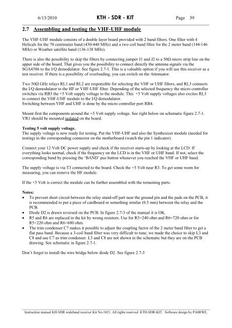
2.7 Assembling and testing the VHF-UHF module<br />
The VHF-UHF module consists of a double layer board provided with 2 band filters. One filter with 4<br />
Helicals for the 70 centimeter band (430-440 MHz) and a two coil band filter for the 2 meter band (144-146<br />
MHz) or Weather satellite band (136-138 MHz).<br />
There is also the possibility to skip the filters by connecting jumper J1 and J2 to a 50Ω micro strip line on the<br />
upper side of the board. That gives you the possibility to connect directly the antenna signals via the<br />
SGA4586 to the I/Q demodulator. See figure 2.7-1. This is a valuable option if you will use this receiver as a<br />
test receiver. If there is a possibility of overloading, you can switch on the Attenuator.<br />
Two 50Ω GHz relays RL1 and RL2 are responsible for selecting the VHF or UHF filters, and RL3 connects<br />
the I/Q demodulator to the HF or VHF-UHF filter. Depending of the selected frequency the micro controller<br />
switches via RB3 the +5 Volt supply voltage to the module. This +5 Volt supply voltages also excites RL3<br />
to connect the VHF-UHF module to the I/Q demodulator.<br />
Switching between VHF and UHF is done by the micro controller port RB4.<br />
Mount first the components around the +5 Volt supply voltage. See right below on schematic figure 2.7-1.<br />
VR1 should be mounted isolated on the board.<br />
Testing 5 volt supply voltage.<br />
The supply voltage is now ready for testing. Put the VHF-UHF and also the Synthesizer module (needed for<br />
testing) in the corresponding connector on the motherboard (watch the pin 1 indicator).<br />
Connect your 12 Volt DC power supply and check if the receiver starts-up by looking at the LCD. If<br />
everything looks normal, check if the frequency on the LCD is in the VHF or UHF band. If not, select the<br />
corresponding band by pressing the ‘BAND’ pus button whenever you reached the VHF or UHF band.<br />
The supply voltage is via T3 connected to the board. Check the +5 Volt near R3. To get some room for<br />
measuring, you can remove the HF module.<br />
If the +5 Volt is correct the module can be further assembled with the remaining parts.<br />
Notes:<br />
• To prevent short circuit between the relay stand-off part near the ground pin and the pads on the PCB, it<br />
is recommended to put a piece of cardboard or something similar (0.5 mm) between the relay and the<br />
PCB.<br />
• Diode D2 is drawn reversed on the PCB. In figure 2.7-3 of the manual it is OK.<br />
• R5 and R6 are replaced in the <strong>kit</strong> by wrong resistors. Use for R5=240 ohm and R6=720 ohm or for<br />
R5=220 ohm and R6=680 ohm.<br />
• The trim condenser C7 makes it possible to adjust the coupling factor of the 2 meter band filter to get a<br />
flat pass band. Because a 3-coil band filter was very difficult to tune, we made the choice to skip L3 and<br />
C8 and use C7 as trim condenser. L3 and C8 are not shown in the schematic but they are on the PCB<br />
drawing. See schematic in figure 2.7-1.<br />
Don’t forget to install the wire bridge below diode D2. See figure 2.7-3<br />
___________________________________________________________________________________________________________<br />
Instruction manual KH-SDR wideband receiver Kit No-1021. All rights reserved KTH-SDR-KIT. Software design by PA0RWE.


