impact of microvia-in-pad design on void formation - Sanmina-SCI
impact of microvia-in-pad design on void formation - Sanmina-SCI
impact of microvia-in-pad design on void formation - Sanmina-SCI

You also want an ePaper? Increase the reach of your titles
YUMPU automatically turns print PDFs into web optimized ePapers that Google loves.
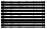
Test 6: Effect <str<strong>on</strong>g>of</str<strong>on</strong>g> Via-Hole Layer Depth<br />
Via layer depth is def<str<strong>on</strong>g>in</str<strong>on</strong>g>ed as the start<str<strong>on</strong>g>in</str<strong>on</strong>g>g and end<str<strong>on</strong>g>in</str<strong>on</strong>g>g layer<br />
<str<strong>on</strong>g>of</str<strong>on</strong>g> the via-hole. PTH def<str<strong>on</strong>g>in</str<strong>on</strong>g>es a via-hole go<str<strong>on</strong>g>in</str<strong>on</strong>g>g through the<br />
entire board – <str<strong>on</strong>g>in</str<strong>on</strong>g> this case layer 1 to layer 8. Via-Hole<br />
layer depth showed much lower <strong>void</strong><str<strong>on</strong>g>in</str<strong>on</strong>g>g for go<str<strong>on</strong>g>in</str<strong>on</strong>g>g from<br />
layer 1 to layer 2 than for layer 1 to layer 3. The PTH viaholes<br />
did show lower <strong>void</strong><str<strong>on</strong>g>in</str<strong>on</strong>g>g than layer 1 to layer 3.<br />
12000<br />
10000<br />
8000<br />
6000<br />
4000<br />
2000<br />
0<br />
Dimensi<strong>on</strong> <str<strong>on</strong>g>in</str<strong>on</strong>g> mils<br />
Dimensi<strong>on</strong> <str<strong>on</strong>g>in</str<strong>on</strong>g> mils<br />
Dimensi<strong>on</strong> <str<strong>on</strong>g>in</str<strong>on</strong>g> mils<br />
16<br />
14<br />
12<br />
10<br />
8<br />
6<br />
4<br />
2<br />
0<br />
14<br />
12<br />
10<br />
8<br />
6<br />
4<br />
2<br />
0<br />
16<br />
14<br />
12<br />
10<br />
8<br />
6<br />
4<br />
2<br />
0<br />
Total Number <str<strong>on</strong>g>of</str<strong>on</strong>g> Voids<br />
Lyr 1 to 2 Lyr 1 to 3 PTH<br />
Via=Hole Layer Depth<br />
Middle Slice<br />
Top Slice<br />
Slice 1 - Middle (Total Void Count - 18,698)<br />
Mean Std Dev. Range M<str<strong>on</strong>g>in</str<strong>on</strong>g>imum Maximum<br />
Slice 2 - Top (Total Void Count - 6,801)<br />
Mean Std Dev. Range M<str<strong>on</strong>g>in</str<strong>on</strong>g>imum Maximum<br />
Slice 3 - Bottom (Total Void Count - 17,846)<br />
Mean Std Dev. Range M<str<strong>on</strong>g>in</str<strong>on</strong>g>imum Maximum<br />
Bottom Slice<br />
Lyr 1 to 2<br />
Lyr 1 to 3<br />
PTH<br />
Lyr 1 to 2<br />
Lyr 1 to 3<br />
PTH<br />
Lyr 1 to 2<br />
Lyr 1 to 3<br />
PTH<br />
SUMMARY OF RESULTS<br />
• In general the .093 boards produced less <strong>void</strong><str<strong>on</strong>g>in</str<strong>on</strong>g>g than<br />
the .062 boards. Approx. 15% difference was<br />
observed.<br />
• There were about a 25% <str<strong>on</strong>g>in</str<strong>on</strong>g>crease <str<strong>on</strong>g>in</str<strong>on</strong>g> the number <str<strong>on</strong>g>of</str<strong>on</strong>g><br />
<strong>void</strong>s for the bottom slice <strong>on</strong> the Ag versus Au<br />
boards.<br />
• With the excepti<strong>on</strong> <str<strong>on</strong>g>of</str<strong>on</strong>g> the 1.27 mm BGA as pitch<br />
decreased so did the occurrence <str<strong>on</strong>g>of</str<strong>on</strong>g> <strong>void</strong>s. There was<br />
a large decrease as the pitch went down to .8 mm and<br />
then a slight decrease as the pitch went from .8 mm<br />
to .5 mm.<br />
• The locati<strong>on</strong> <str<strong>on</strong>g>of</str<strong>on</strong>g> the via-hole had an effect <strong>on</strong> <strong>void</strong><br />
formati<strong>on</strong>. With the via-hole located <str<strong>on</strong>g>in</str<strong>on</strong>g> the center <str<strong>on</strong>g>of</str<strong>on</strong>g><br />
the <str<strong>on</strong>g>pad</str<strong>on</strong>g> (for both through hole and micro-via) there<br />
was an <str<strong>on</strong>g>in</str<strong>on</strong>g>crease <str<strong>on</strong>g>in</str<strong>on</strong>g> <strong>void</strong><str<strong>on</strong>g>in</str<strong>on</strong>g>g. As the via-hole moved<br />
further away from the center <str<strong>on</strong>g>of</str<strong>on</strong>g> the <str<strong>on</strong>g>pad</str<strong>on</strong>g>, <strong>void</strong><str<strong>on</strong>g>in</str<strong>on</strong>g>g<br />
decreased.<br />
• The via-hole size had a dramatic effect <strong>on</strong> <strong>void</strong><br />
formati<strong>on</strong>. Out <str<strong>on</strong>g>of</str<strong>on</strong>g> all <strong>void</strong>s found, the 4 mil via<br />
accounted for 6% <str<strong>on</strong>g>of</str<strong>on</strong>g> the total. This was followed by<br />
the 6 mil via-holes, which accounted for 40% and<br />
then the 8 mil via-hole at 54%.<br />
• Via-Hole layer depth also proved to have a large<br />
<str<strong>on</strong>g>impact</str<strong>on</strong>g> <strong>on</strong> <strong>void</strong> formati<strong>on</strong>. Out <str<strong>on</strong>g>of</str<strong>on</strong>g> al the <strong>void</strong>s found<br />
the layer 1 to layer 2 via-holes accounted for 12% <str<strong>on</strong>g>of</str<strong>on</strong>g><br />
the total. Next <str<strong>on</strong>g>in</str<strong>on</strong>g> number was the through hole via at<br />
32%. The largest percentage came from the via-hole<br />
go<str<strong>on</strong>g>in</str<strong>on</strong>g>g from layer 1 to layer 3 with 56% <str<strong>on</strong>g>of</str<strong>on</strong>g> the total.<br />
CONCLUSIONS<br />
The optimum VIP <str<strong>on</strong>g>design</str<strong>on</strong>g> is <strong>on</strong>e where the via-hole<br />
locati<strong>on</strong> is <str<strong>on</strong>g>of</str<strong>on</strong>g>fset from the center <str<strong>on</strong>g>of</str<strong>on</strong>g> the <str<strong>on</strong>g>pad</str<strong>on</strong>g> and as small<br />
as possible.<br />
Based <strong>on</strong> current IPC 610-C guidel<str<strong>on</strong>g>in</str<strong>on</strong>g>es for solder jo<str<strong>on</strong>g>in</str<strong>on</strong>g>t<br />
<strong>void</strong><str<strong>on</strong>g>in</str<strong>on</strong>g>g, us<str<strong>on</strong>g>in</str<strong>on</strong>g>g BGA patterns 2 & 3 (see Figure 2) will<br />
meet the 25% criteria stated. For the other <str<strong>on</strong>g>pad</str<strong>on</strong>g> <str<strong>on</strong>g>design</str<strong>on</strong>g>s<br />
mixed results were observed and further analysis needs to<br />
be performed <strong>on</strong> these <str<strong>on</strong>g>pad</str<strong>on</strong>g> <str<strong>on</strong>g>design</str<strong>on</strong>g>s.<br />
The c<strong>on</strong>clusi<strong>on</strong>s given here are based <strong>on</strong> assembly criteria<br />
<strong>on</strong>ly and another phase <str<strong>on</strong>g>of</str<strong>on</strong>g> this project will address the<br />
PCB issues. In additi<strong>on</strong> to further analyz<str<strong>on</strong>g>in</str<strong>on</strong>g>g the results<br />
obta<str<strong>on</strong>g>in</str<strong>on</strong>g>ed so far additi<strong>on</strong>al work will be required to address<br />
the <str<strong>on</strong>g>impact</str<strong>on</strong>g> <strong>on</strong> high volume manufactur<str<strong>on</strong>g>in</str<strong>on</strong>g>g.<br />
REFERENCES<br />
[1] Arledge, K. and Swirbel, T., "Microvias <str<strong>on</strong>g>in</str<strong>on</strong>g> Pr<str<strong>on</strong>g>in</str<strong>on</strong>g>ted<br />
Circuit Boards", www.ipc.org/html/s08-1.pdf, 1998, pp.<br />
S08-1-1 - S08-1-9<br />
[2] Burgess, L. and Madden, P., "Putt<str<strong>on</strong>g>in</str<strong>on</strong>g>g Bl<str<strong>on</strong>g>in</str<strong>on</strong>g>d Vias <str<strong>on</strong>g>in</str<strong>on</strong>g><br />
SMD Pads: Where They Bel<strong>on</strong>g", Proceed<str<strong>on</strong>g>in</str<strong>on</strong>g>gs - Surface<br />
Mount Internati<strong>on</strong>al, www.laservia.com/PDF/smi97.pdf,<br />
September 1997