Digital image stabilization - Computer Graphics Laboratory
Digital image stabilization - Computer Graphics Laboratory
Digital image stabilization - Computer Graphics Laboratory

You also want an ePaper? Increase the reach of your titles
YUMPU automatically turns print PDFs into web optimized ePapers that Google loves.
s found in Step 2 and estimates camera<br />
iteration.<br />
f the translation.<br />
ight estimation result passes sanity testing.<br />
e next step.Otherwise repeat from Step 7.<br />
on to move.<br />
until Thread A nishes Step 5 and updates<br />
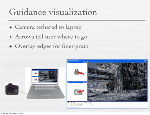
Guidance visualization<br />
✦ Camera tethered to laptop<br />
ow chart of our interleaved scheme.<br />
✦ Arrows tell user where to go<br />
. For each resulting pose, we perform three<br />
e our visualization is reliable. We compare<br />
ructed from each frame with our initial 3D<br />
first two <strong>image</strong>s. We measure the 3D error<br />
the pose estimation if the median of the 3D<br />
. Typically, the median error is less than<br />
✦ Overlay edges for finer grain<br />
Computational Re-Photography • 3<br />
k if the current camera pose result is cones.<br />
We found that a simple filter works, alr<br />
[Kalman 1960] would likely generate a<br />
measure the mean and the standard deviaions<br />
at the previous ten frames and confirm<br />
d camera location is within 4 standard de-<br />
. We assume the camera motion is smooth<br />
small. The above two tests typically detect<br />
once in 100 frames.<br />
structure degeneracy caused when all the<br />
ingle plane in the scene. We find the bestg<br />
RANSAC with 1.5 pixel average mapterations.<br />
If the number of homography inof<br />
Tuesday, the February epipolar 23, 2010<br />
geometry inliers, we ignore<br />
. 3. In our prototype implementation, a laptop is connected to a camera.<br />
laptop computes the relative camera pose and visualizes how to transthe<br />
camera with two 2D arrows. Our alignment visualization, which<br />
sists of edges detected from the reference <strong>image</strong> composited onto the<br />
translation to the user. We automatically compute the best camera<br />
rotation between the current and reference views, and apply this<br />
rotation as a warp before displaying the current frame. This rotation<br />
alignment allows the user to focus on translating the camera in<br />
the right direction without striving to hold the camera in the right<br />
orientation.<br />
The effect of a 3D camera rotation and zoom can be described<br />
with an infinite homography [Hartley and Zisserman 2000]. The<br />
infinite homography is a subclass of the general homography, as it<br />
is restricted to rigid camera rotations and zooms. We use the algorithm<br />
of Brown et al. [2007] to compute the infinite homography<br />
that fits all the epipolar geometry inliers with the least squared error.<br />
5. VISUALIZATION<br />
Fig. 9. A screen capture of our visualization, including our primary visual