A Physically-Based Night Sky Model - Computer Graphics Laboratory
A Physically-Based Night Sky Model - Computer Graphics Laboratory
A Physically-Based Night Sky Model - Computer Graphics Laboratory

You also want an ePaper? Increase the reach of your titles
YUMPU automatically turns print PDFs into web optimized ePapers that Google loves.
Abstract<br />
To appear in the SIGGRAPH conference proceedings<br />
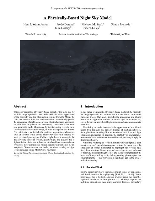
A <strong>Physically</strong>-<strong>Based</strong> <strong>Night</strong> <strong>Sky</strong> <strong>Model</strong><br />
Henrik Wann Jensen 1 Frédo Durand 2 Michael M. Stark 3 Simon Premoˇze 3<br />
Julie Dorsey 2 Peter Shirley 3<br />
1 Stanford University 2 Massachusetts Institute of Technology 3 University of Utah<br />
This paper presents a physically-based model of the night sky for<br />
realistic image synthesis. We model both the direct appearance<br />
of the night sky and the illumination coming from the Moon, the<br />
stars, the zodiacal light, and the atmosphere. To accurately predict<br />
the appearance of night scenes we use physically-based astronomical<br />
data, both for position and radiometry. The Moon is simulated<br />
as a geometric model illuminated by the Sun, using recently measured<br />
elevation and albedo maps, as well as a specialized BRDF.<br />
For visible stars, we include the position, magnitude, and temperature<br />
of the star, while for the Milky Way and other nebulae we<br />
use a processed photograph. Zodiacal light due to scattering in the<br />
dust covering the solar system, galactic light, and airglow due to<br />
light emission of the atmosphere are simulated from measured data.<br />
We couple these components with an accurate simulation of the atmosphere.<br />
To demonstrate our model, we show a variety of night<br />
scenes rendered with a Monte Carlo ray tracer.<br />
Keywords: Natural Phenomena, Atmospheric Effects, Illumination, Rendering, Ray<br />
Tracing<br />
1 Introduction<br />
In this paper, we present a physically-based model of the night sky<br />
for image synthesis, and demonstrate it in the context of a Monte<br />
Carlo ray tracer. Our model includes the appearance and illumination<br />
of all significant sources of natural light in the night sky,<br />
except for rare or unpredictable phenomena such as aurora, comets,<br />
and novas.<br />
The ability to render accurately the appearance of and illumination<br />
from the night sky has a wide range of existing and potential<br />
applications, including film, planetarium shows, drive and flight<br />
simulators, and games. In addition, the night sky as a natural phenomenon<br />
of substantial visual interest is worthy of study simply for<br />
its intrinsic beauty.<br />
While the rendering of scenes illuminated by daylight has been<br />
an active area of research in computer graphics for many years, the<br />
simulation of scenes illuminated by nightlight has received relatively<br />
little attention. Given the remarkable character and ambiance<br />
of naturally illuminated night scenes and their prominent role in the<br />
history of image making — including painting, photography, and<br />
cinematography — this represents a significant gap in the area of<br />
realistic rendering.<br />
1.1 Related Work<br />
Several researchers have examined similar issues of appearance<br />
and illumination for the daylight sky [6, 19, 30, 31, 34, 42]. To our<br />
knowledge, this is the first computer graphics paper that describes<br />
a general simulation of the nighttime sky. Although daytime and<br />
nighttime simulations share many common features, particularly
Figure 1: Elements of the night sky. Not to scale.<br />
the scattering of light from the Sun and Moon, the dimmer nighttime<br />
sky reveals many astronomical features that are invisible in<br />
daytime and thus ignored in previous work. Another issue unique<br />
to nighttime is that the main source of illumination, the Moon, has<br />
its own complex appearance and thus raises issues the Sun does<br />
not. Accurately computing absolute radiances is even more important<br />
for night scenes than day scenes. If all intensities in a day<br />
scene are doubled, a tone-mapped image will change little because<br />
contrasts do not change. In a night scene, however, many image<br />
features may be near the human visibility threshold, and doubling<br />
them would move them from invisible to visible.<br />
Some aspects of the night sky have been examined in isolation.<br />
In a recent paper, Oberschelp and Hornug provided diagrammatic<br />
visualizations of eclipses and planetary conjunction events [32].<br />
Their focus is the illustration of these events, not their realistic rendering.<br />
Researchers have created detailed models of the appearance<br />
of Saturn [3, 4] and Jupiter [47]. These models were intended for<br />
simulation of space scenes and would be overkill for renderings of<br />
Earth scenes. Baranoski et al. did a careful simulation of the aurora<br />
borealis [1]. Although we do not simulate aurora phenomena<br />
in our model, the techniques of Baranoski et al. could be added<br />
seamlessly to our simulations because aurora are an emission phenomenon<br />
with little correlation to the Earth’s position relative to<br />
the Sun, and thus can be added independently to other nighttime<br />
effects.<br />
1.2 Overview<br />
The next section introduces the components of our model. Section 3<br />
describes astronomical models to compute the accurate positions of<br />
the elements of the night sky in a framework appropriate for use in<br />
computer graphics. Sections 4–6 introduce our approach for modeling<br />
and rendering the key sources of illumination in the night sky.<br />
We discuss our implementation and results in Section 7. Finally<br />
we conclude in Section 8 with some discussion and directions for<br />
future work.<br />
2 Sources of <strong>Night</strong> Illumination<br />
To create realistic images of night scenes, we must model the characteristics<br />
of nighttime illumination sources, both in terms of their<br />
contribution to the scene, and their direct appearance in the sky.<br />
These sources are illustrated in Figures 1 and 2 and summarized<br />
below.<br />
• The Moon. Most of the visible moonlight is actually sunlight,<br />
incident on the Moon and scattered from its surface in<br />
all directions. Light received directly from the Moon and<br />
moonlight scattered by the atmosphere account for most of<br />
the available light at night. The appearance of the Moon itself<br />
is important in the night sky due to its proximity to and<br />
visibility from the Earth.<br />
To appear in the SIGGRAPH conference proceedings<br />
2<br />
Component Irradiance [W/m 2 ]<br />
Sunlight 1.3 · 10 3<br />
Full Moon 2.1 · 10 −3<br />
Bright planets 2.0 · 10 −6<br />
Zodiacal light 1.2 · 10 −7<br />
Integrated starlight 3.0 · 10 −8<br />
Airglow 5.1 · 10 −8<br />
Diffuse galactic light 9.1 · 10 −9<br />
Cosmic light 9.1 · 10 −10<br />
Figure 2: Typical values for sources of natural illumination at night.<br />
• The Sun. The sunlight scattered around the edge of the Earth<br />
makes a visible contribution at night. During “astronomical<br />
twilight” the sky is still noticeably bright. This is especially<br />
important at latitudes greater than 48 ◦ N or S, where astronomical<br />
twilight lasts all night in midsummer.<br />
• The planets and stars. Although the light received from the<br />
stars is important as an illumination source only on moonless<br />
nights, the appearance of stars in the sky is crucial for night<br />
scenes. The illumination and appearance of the other planets<br />
are comparable to that of bright stars.<br />
• Zodiacal light. The solar system contains dust particles that<br />
scatter sunlight toward the Earth. This light changes the appearance<br />
and the illumination of the night sky.<br />
• Airglow. The atmosphere has an intrinsic emission of visible<br />
light due to photochemical luminescence from atoms and<br />
molecules in the ionosphere. This accounts for one sixth of<br />
the light in the moonless night sky.<br />
• Diffuse galactic and cosmic light. Light from galaxies other<br />
than the Milky Way.<br />
The atmosphere also plays an important role in the appearance of<br />
the night sky. It scatters and absorbs light and is responsible for a<br />
significant amount of indirect illumination.<br />
In general, the above sources cannot be observed simultaneously<br />
in the night sky. In particular, the dimmest phenomena can only be<br />
seen on moonless nights. In fact, the various components of night<br />
light are only indirectly related to one another; hence, we treat them<br />
separately in our model.<br />
2.1 <strong>Model</strong> Overview<br />
The main components of our model are illustrated Figure 3 and outlined<br />
below. Subsequent sections will discuss each of these components<br />
in greater detail.<br />
Our general approach is to model the direct appearance of the<br />
celestial elements and the illumination they produce differently, as<br />
the latter requires less accuracy and a simpler model is easier to<br />
integrate and introduces less variance. We demonstrate our model<br />
in a spectral rendering context; however the data can be converted<br />
to the CIE XYZV color space (including a scotopic component V<br />
for rod vision).<br />
• Astronomical positions. We summarize classical astronomical<br />
models and provide a simplified framework to compute<br />
accurate positions of the Sun, Moon, and stars.<br />
• Moon. The Moon is simulated as explicit geometry illuminated<br />
by two directional light sources, the Sun and the Earth.<br />
We include a model based on elevation and albedo data of the<br />
surface of the Moon, and on a specialized BRDF description.<br />
A simpler model is presented for the illumination from the<br />
Moon.
star catalogue<br />
Milky Way<br />
map<br />
uniform<br />
starlight<br />
Moon<br />
zodiacal<br />
light<br />
earthlight<br />
sunlight<br />
j<br />
airglow<br />
To appear in the SIGGRAPH conference proceedings<br />
atmosphere<br />
scattering<br />
airglow layer<br />
Earth<br />
Figure 3: Components of the night sky model.<br />
atmosphere<br />
• Stars. The appearance of the brightest stars is simulated using<br />
data that takes into account their individual position, magnitude<br />
and temperature. Planets are displayed similarly, albeit<br />
by first computing their positions. Star clouds — elements<br />
that are too dim to observe as individual stars but collectively<br />
produce visible light — including the Milky Way, are simulated<br />
using a high resolution photograph of the night sky processed<br />
to remove the bright stars. Illumination from stars is<br />
treated differently, using a simple constant model.<br />
• Other astronomical elements. Zodiacal light, atmospheric<br />
airglow, diffuse galactic light, and cosmic lights are simulated<br />
using measured data.<br />
• Atmospheric scattering. We simulate multiple scattering in<br />
the atmosphere due to both molecules and aerosols.<br />
3 Astronomical Positions<br />
We introduce classical astronomical formulas to compute the position<br />
of various celestial elements. For this, we need to review<br />
astronomical coordinate systems. This section makes simplifications<br />
to make this material more accessible. For a more detailed<br />
description, we refer the reader to classic textbooks [7, 10, 23, 24]<br />
or to the year’s Astronomical Almanac [44].<br />
All of the formulas in the Appendix have been adapted from high<br />
accuracy astronomical formulas [23]. They have been simplified to<br />
facilitate subsequent implementation, as computer graphics applications<br />
usually do not require the same accuracy as astronomical<br />
applications. We have also made conversions to units that are more<br />
familiar to the computer graphics community. Our implementation<br />
usually uses higher precision formulas, but the error introduced by<br />
the simplifications is lower than 8 minutes of arc over five centuries.<br />
3.1 Coordinate Systems<br />
The basic idea of positional astronomy is to project everything onto<br />
celestial spheres. Celestial coordinates are then spherical coordinates<br />
analogous to the terrestrial coordinates of longitude and latitude.<br />
We will use three coordinate systems (Figure 4) — two centered<br />
on the Earth (equatorial and ecliptic) and one centered on the<br />
observer (horizon). Conversion formulas are given in the Appendix.<br />
The final coordinate system is the local spherical frame of the<br />
observer (horizon system). The vertical axis is the local zenith, the<br />
3<br />
Equator<br />
Ecliptic<br />
e<br />
Vernal<br />
Equinox<br />
a<br />
North<br />
Pole<br />
l<br />
d<br />
b<br />
horizon<br />
Equator<br />
South<br />
Pole<br />
£¥¤§¦<br />
¢¡<br />
h<br />
A<br />
local<br />
zenith<br />
Figure 4: Coordinate systems. Left: equatorial (α, δ) and ecliptic<br />
(λ, β). Right: Local coordinates (A, h) for an observer at longitude<br />
lon and latitude lat.<br />
latitude is the altitude angle h above the horizon, and the longitude,<br />
or azimuth A, is measured eastward from the south direction<br />
(Figure 4).<br />
The two other systems are centered on the Earth but do not depend<br />
on its rotation. They differ by their vertical axis, either the<br />
North pole (and thus the axis of rotation of the Earth) for the equatorial<br />
system, or the normal to the ecliptic, the plane of the orbit of<br />
the Earth about the Sun, for the ecliptic system (Figures 1 and 4).<br />
The Earth’s rotational axis remains roughly parallel as the Earth<br />
orbits around the Sun (the angle between the ecliptic and the Equator<br />
is about 23.44 ◦ ). This means that the relationship between the<br />
angles of the two systems does not vary. In both cases, the reference<br />
for the longitude is the Vernal Equinox, denoted , which<br />
corresponds to the intersection of the great circles of the Equator<br />
and the ecliptic (Figure 4).<br />
However, the direction of the axis of the Earth is not quite constant.<br />
Long-term variations known as precession and short-term oscillations<br />
known as nutations have to be included for high accuracy,<br />
as described in the Appendix.<br />
3.2 Position of the Sun<br />
The positions of the Sun and Moon are computed in ecliptic coordinates<br />
(λ, β) and must be converted using the formulas in Appendix.<br />
We give a brief overview of the calculations involved. Formulas exhibit<br />
a mean value with corrective trigonometric terms (similar to<br />
Fourier series).<br />
The ecliptic latitude of the Sun should by definition be βSun =<br />
0. However, small corrective terms may be added for very high<br />
precision, but we omit them since they are below 10 ′′ .<br />
3.3 The Moon<br />
The formula for the Moon is much more involved because of the<br />
perturbations caused by the Sun. It thus requires many corrective<br />
terms. An error of 1 ◦ in the Moon position corresponds to as much<br />
as 2 diameters. We also need to compute the distance dMoon, which<br />
is on average 384 000 km. The orbital plane of the Moon is inclined<br />
by about 5 ◦ with respect to the ecliptic. This is why solar and lunar<br />
eclipses do not occur for each revolution and are therefore rare.<br />
The Moon orbits around the Earth with the same rotational speed<br />
as it rotates about itself. This is why we always see nearly the<br />
same side. However, the orbit of the Moon is not a perfect circle<br />
but an ellipse (eccentricity about 1/18), and its axis of revolution<br />
is slightly tilted with respect to the plane of its orbit (Figure 5).<br />
For this reason, about 59% of the lunar surface can be seen from<br />
the Earth. These apparent oscillations are called librations and are
true axis<br />
of rotation<br />
exact circle<br />
true orbit<br />
Earth<br />
To appear in the SIGGRAPH conference proceedings<br />
Moon<br />
orthogonal<br />
axis<br />
Figure 5: (a) Librations of the Moon are due to the eccentricity of<br />
its orbit and to the tilt of its axis of rotation. (b) Angle for the BRDF<br />
of the Moon.<br />
included in our model as a result of our direct modeling approach.<br />
(See the Appendix for formulas.)<br />
3.4 Position of Stars<br />
For the stars, we used the Yale Bright Star Catalog [14]. It contains<br />
about 9000 stars, including the roughly 6000 visible to the naked<br />
eye. The stellar positions are given in equatorial coordinates. The<br />
catalogue contains the position for 2000 A.D. and the proper motion<br />
of stars, caused by their rectilinear motion through space. The<br />
position of a star for a given date is then computed using a linear approximation,<br />
usually in rectangular coordinates (the apparent motion<br />
can be neglected if the date is less than 5 centuries from 2000<br />
A.D.). The positions of the planets are computed using formulas<br />
similar to those used for the Moon and the Sun [23].<br />
4 Moonlight<br />
The large-scale topography of the Moon is visible from the Earth’s<br />
surface, so we render its direct appearance using a geometric model<br />
containing elevation and albedo illuminated by two directional light<br />
sources, the Earth and the Sun.<br />
4.1 <strong>Model</strong>ing the Moon<br />
To model the Moon accurately, we use the positions computed in<br />
the previous section and measured data of the lunar topography and<br />
albedo [27]. The Moon is considered a poor reflector: on average<br />
only 7.2% of the light is reflected [20]. The albedo is used to modulate<br />
a BRDF model, which we present in the next section. The<br />
elevation is measured with a precision of a quarter of a degree in<br />
longitude and latitude (1440 × 720), and the albedo map has size<br />
800 × 400.<br />
The Moon is illuminated by the Sun, which can be treated as a<br />
directional light source. We use the positions of the Moon and Sun<br />
to determine the direction of illumination. The Sun is modeled as a<br />
black body at temperature 5900K (see Appendix for conversion),<br />
and power 1905 W<br />
m2 . The Sun appears about 1.44 times brighter<br />
from the Moon than from the surface of the Earth because of the<br />
absence of atmosphere. We do not include the Earth as an occluder,<br />
which means we cannot simulate lunar eclipses. This could easily<br />
be done by modeling the Sun as a spherical light source to simulate<br />
penumbra.<br />
The faint light visible on the dark side of the Moon when it is a<br />
thin crescent is known as earthshine. Earthshine depends strongly<br />
on the phase of the Earth. When the Earth is full (at new Moon), it<br />
casts the greatest amount of light on the Moon, and the earthshine<br />
is relatively bright and easily observed by the naked eye. We model<br />
earthshine explicitly by including the Earth as a second light source<br />
for the Moon surface.<br />
4<br />
normal<br />
qr<br />
qi<br />
a<br />
reflected<br />
light<br />
incoming<br />
light<br />
albedo<br />
map<br />
v u<br />
Figure 6: Angle for the BRDF of the Moon.<br />
Accuracy is not crucial for earthshine except for the new Moon,<br />
so we simply use the percentage of lit Earth visible from the Moon<br />
and multiply it by the intensity of the full earthshine, which is<br />
0.19 W<br />
m2 . Given the Earth phase, that is, the angle π − ϕ between<br />
the Moon and the Sun as seen from the Earth (the opposite of the<br />
Moon phase ϕ), we obtain [46]:<br />
�<br />
Eem = 0.19∗0.5 1 − sin(<br />
4.2 BRDF of the Moon<br />
π − ϕ<br />
) tan(<br />
2<br />
π − ϕ<br />
) ln(cot(<br />
2<br />
π − ϕ<br />
�<br />
))<br />
4<br />
(1)<br />
The Moon has a low albedo and a reddish color, and it exhibits<br />
backscattering reflection (it is much brighter at full Moon) [11].<br />
Furthermore, the apparent disc of the full Moon has a remarkable<br />
photometric property: its average brightness at the center is the<br />
same as at the edge [11]. The Moon is therefore said to exhibit<br />
no limb darkening. This can be explained by the pulverized nature<br />
of its surface. We use the complete Hapke-Lommel-Seeliger<br />
model of the reflectance function of the Moon, which provides a<br />
good approximation to the real appearance and a good fit to measured<br />
data [12]. The BRDF f consists of a retrodirective function<br />
B and a scattering function S. As the BRDF of the Moon is rather<br />
uniform, but the albedo is variable, we model them independently.<br />
We multiply the BRDF by the albedo and by the spectrum of the<br />
Moon.<br />
The geometry for the BRDF is summarized in Figure 6. ϕ is<br />
the lunar phase angle (angle Sun-Earth as seen from the Moon, or<br />
equivalently for our purpose, the angle between incident and reflected<br />
light). θr is the angle between the reflected light and the<br />
surface normal; θi is the angle between the incident light and the<br />
surface normal.<br />
Note that to compute the contribution of the earthshine, the Sun<br />
has to be replaced by the Earth using Equation 1 for the intensity.<br />
ϕ is then null by definition.<br />
The BRDF, f, of the Moon can be computed with:<br />
f(θi, θr, ϕ) = 2<br />
1<br />
B(ϕ, g)S(ϕ)<br />
. (2)<br />
3π 1 + cos θr/ cos θi<br />
The retrodirective function B(ϕ, g) is given by<br />
B(ϕ, g) =<br />
� 2 − tan ϕ<br />
2g<br />
�<br />
�<br />
−g/ tan<br />
1 − e<br />
ϕ� −g/ tan<br />
3 − e<br />
ϕ�<br />
, ϕ < π/2<br />
1, ϕ ≥ π/2,<br />
(3)<br />
where g is a surface density parameter which determines the sharpness<br />
of the peak at the full Moon. We use g = 0.6, although values<br />
between 0.4 (for rays) and 0.8 (for craters) could be used.<br />
The scattering law S for individual objects is given by [12]:<br />
S(ϕ) =<br />
sin |ϕ| + (π − |ϕ|) cos |ϕ|<br />
π<br />
+ t<br />
�<br />
1 − 1<br />
cos |ϕ|<br />
2<br />
� 2<br />
, (4)<br />
where t introduces a small amount of forward scattering that arises<br />
from large particles that cause diffraction [37]. t = 0.1 is a good fit<br />
to Rougier’s measurements [16] of the light from the Moon.
The spectrum of the Moon is distinctly redder than the Sun’s<br />
spectrum. Indeed, the lunar surface consists of a layer of a porous<br />
pulverized material composed of particles larger than the wavelengths<br />
of visible light. As a consequence and in accordance with<br />
the Mie theory [45], the albedo is approximately twice as large for<br />
red (longer wavelengths) light than for blue (shorter wavelengths)<br />
light. In practice, we use a spectral reference that is a normalized<br />
linear ramp (from 70% at 340nm to 135% at 740nm). In addition,<br />
light scattered from the lunar surface is polarized, but we do not<br />
include polarization in our model. Figure 7 demonstrates our Moon<br />
model for various conditions.<br />
4.3 Illumination from the Moon<br />
For illumination coming from the Moon, it is sufficient to use a simple<br />
directional model since the Moon is very distant. This moreover<br />
introduces less variance in the illumination integration.<br />
Using the Lommel-Seeliger law [46], the irradiance Em from<br />
the Moon at phase angle ϕ and a distance d can be expressed as:<br />
Em(ϕ, d) = 2 C r2 m<br />
3 d 2<br />
To appear in the SIGGRAPH conference proceedings<br />
� � ϕ ϕ<br />
Eem + Esm 1 − sin 2 tan 2 log � cot ϕ ���<br />
4 ,<br />
(5)<br />
where rm is the radius of the Moon, Esm is the irradiance from the<br />
Sun at the surface of the Moon, and Eem is the earthshine contribution<br />
as computed from Equation 1. Recall that the phase angle of<br />
the Moon with respect to earthshine is always null. The normalizing<br />
constant C is the average albedo of the Moon (C = 0.072).<br />
5 Starlight<br />
Stars are important visual features in the sky. We use actual star<br />
positions (as described in Section 3.4), and brightnesses and colors<br />
from the same star catalogue [14]. In this section, we describe<br />
how stars are included in our model, present the calculation of their<br />
brightness and chromaticity, and finally, discuss the illumination<br />
coming from stars.<br />
5.1 Rendering Stars<br />
Stars are very small, and it is therefore not practical to use explicit<br />
ray tracing to render them as rays would easily miss them. Instead,<br />
we use an image-based approach in which a separate star image is<br />
generated and composited using an alpha image that models attenuation<br />
in the atmosphere. The use of the alpha image ensures that the<br />
intensity of the stars is correctly reduced due to scattering and absorption<br />
in the atmosphere. The alpha map records for every pixel<br />
the visibility of objects beyond the atmosphere. It is generated by<br />
the ray tracer as a secondary image. Each time a ray from the camera<br />
leaves the atmosphere, the transmitivity is stored in the alpha<br />
image. The star image is multiplied by the alpha image and added<br />
to the rendered image to produce the final image.<br />
For star clusters, such as the Milky Way, where individual stars<br />
are not visible, we use a high resolution (14400x7200) photographic<br />
mosaic of the <strong>Night</strong> <strong>Sky</strong> [25]. The brightest stars were<br />
removed using pattern-matching and median filtering.<br />
5.2 Color and Brightness of Stars<br />
A stellar magnitude describes the apparent star brightness. Given<br />
the visual magnitude, the irradiance at the Earth is [21]:<br />
Es = 10 0.4(−mv−19) W<br />
. (6)<br />
m2 For the Sun, mv ≈ −26.7; for the full Moon, mv ≈ −12.2; and<br />
for Sirius, the brightest star, mv ≈ −1.6. The naked eye can see<br />
5<br />
stars with a stellar magnitude up to approximately 6. However, this<br />
is the visible magnitude, which takes into account the atmospheric<br />
scattering. Since we simulate atmospheric scattering, we must discount<br />
this absorption, which accounts for 0.4 magnitude:<br />
E ′ s = 10 0.4(−mv−19+0.4) W<br />
. (7)<br />
m2 The color of the star is not directly available as a measured spectrum.<br />
Instead, astronomers have established a standard series of<br />
measurements in particular wave-bands. A widely used UBV system<br />
introduced by Johnson [18] isolates bands of the spectrum in<br />
the blue intensity B, yellow-green intensity V , and ultra-violet intensity<br />
U. The difference B − V is called the color index of a star,<br />
which is a numerical measurement of the color. A negative value of<br />
B−V indicates a more bluish color, while a positive value indicates<br />
a redder hue. UBV is not directly useful for rendering purposes.<br />
However, we can use the color index to estimate a star’s temperature<br />
[33, 40]:<br />
7000K<br />
Teff =<br />
. (8)<br />
B − V + 0.56<br />
To compute spectral irradiance from a star given Teff , we first<br />
compute a non-spectral irradiance value from the stellar magnitude<br />
using Equation 7. We then use the computed value to scale a normalized<br />
spectrum based on Planck’s radiation law for black body<br />
radiators [39]. The result is spectral irradiance.<br />
In the color pages (Figure 9) we have rendered a close-up of<br />
stars. We use the physically-based glare filter by Spencer et al. [41]<br />
as a flare model for the stars. This model fits nicely with the observations<br />
by Navarro and Losada [28] regarding the shape of stars as<br />
seen by the human eye.<br />
Figure 10 is a time-lapse rendering of stars. Here we have simulated<br />
a camera and omitted the loss of color by a human observer.<br />
The colors of the stars can be seen clearly in the trails. Notice, also<br />
the circular motion of the stars due to the rotation of the Earth.<br />
5.3 Illumination from Stars<br />
Even though many stars are not visible to the naked eye, there is a<br />
collective contribution from all stars when added together. We use<br />
−8 W<br />
a constant irradiance of 3 · 10 m2 [38] to account for integrated<br />
starlight.<br />
6 Other Elements<br />
A variety of phenomena affect the appearance of the night sky in<br />
subtle ways. While one might assume the sky itself is colored only<br />
by scattered light in the atmosphere, that is in fact only one of four<br />
specific sources of diffuse visible color in the night sky. The other<br />
three are zodiacal light, airglow, and galactic/cosmic light. We include<br />
all of these in our model. These effects are especially important<br />
on moonless nights, when a small change in illumination can<br />
determine whether an object in the scene is visible or invisible.<br />
6.1 Zodiacal Light<br />
The Earth co-orbits with a cloud of dust around the Sun. Sunlight<br />
scatters from this dust and can be seen from the Earth as zodiacal<br />
light [5, 36]. This light first manifests itself in early evening as a<br />
diffuse wedge of light in the southwestern horizon and gradually<br />
broadens with time. During the course of the night the zodiacal<br />
light becomes wider and more upright, although its position relative<br />
to the stars shifts only slightly [2].
The structure of the interplanetary dust is not well-understood.<br />
To to simulate zodiacal light we use a table with measured values<br />
[38]. Whenever a ray exits the atmosphere, we convert the direction<br />
of the ray to ecliptic polar coordinates and perform a bilinear<br />
lookup in the table. This works well since zodiacal light changes<br />
slowly with direction and has very little seasonal variation. A result<br />
of our zodiacal light model is illustrated Figure 8.<br />
6.2 Airglow<br />
Airglow is faint light that is continuously emitted by the entire upper<br />
atmosphere with a main concentration at an elevation of approximately<br />
110 km. The upper atmosphere of the Earth is continually<br />
being bombarded by high energy particles, mainly from<br />
the Sun. These particles ionize atoms and molecules or dissociate<br />
molecules and in turn cause them to emit light in particular spectral<br />
lines (at discrete wavelengths). As the emissions come primarily<br />
from Na and O atoms as well as molecular nitrogen and oxygen the<br />
emission lines are easily recognizable. The majority of the airglow<br />
emissions occur at 557.7nm (O-I), 630nm (O-I) and a 589.0nm -<br />
589.6nm doublet (Na-I). Airglow is the principal source of light in<br />
the night sky on moonless nights.<br />
Airglow is integrated into the simulation by adding an active<br />
layer to the atmosphere (altitude 80km) that contributes a spectral<br />
−8 W<br />
in-scattered radiance (5.1·10 m2 , 3 peaks, at 557.7nm, 583.0nm<br />
and 630.0nm).<br />
6.3 Diffuse Galactic Light and Cosmic Light<br />
Diffuse galactic light and cosmic light are the last components of<br />
the night sky that we include in our model. These are very faint<br />
−8 W<br />
(see Figure 2) and modeled as a constant term (1 · 10 m2 ) that is<br />
added when a ray exits the atmosphere.<br />
6.4 Atmosphere <strong>Model</strong>ing<br />
Molecules and aerosols (dust, water drops and other similar-sized<br />
particles) are the two main constituents of the atmosphere that affect<br />
light. As light travels through the atmosphere it can be scattered<br />
by molecules (Rayleigh scattering) or by aerosols (Mie scattering).<br />
The probability that a scattering event occurs is proportional to the<br />
local density of molecules and aerosols and the optical path length<br />
of the light. The two types of scattering are very different: Rayleigh<br />
scattering is strongly dependent on the wavelength of the light and<br />
it scatters almost diffusely; aerosol scattering is mostly independent<br />
of the wavelength, but with a strong peak in the forward direction<br />
of the scattered light.<br />
We model the atmosphere using a spherical model similar to that<br />
of Nishita et al. [29, 31] and use the same phase functions to approximate<br />
the scattering of light. To simulate light transport with<br />
multiple scattering, we use distribution ray tracing combined with<br />
ray marching. A ray traversing the atmosphere uses ray marching to<br />
integrate the optical depth, and it samples the in-scattered indirect<br />
radiance at random positions in addition to the direct illumination.<br />
Each ray also keeps track of the visibility of the background, and all<br />
rays emanating from the camera save this information in the alpha<br />
image (as discussed in Section 5.1). This method is fairly efficient<br />
because the atmosphere is optically thin. Also, the method is very<br />
flexible and allows us to integrate other components in the atmosphere<br />
such as clouds and airglow.<br />
We model clouds procedurally using an approach similar to the<br />
one described in [9]. Clouds are similar to the atmosphere, but<br />
as they have a higher density, the number of scattering events<br />
will be larger. For clouds we use the Henyey-Greenstein phasefunction<br />
[13] with strong forward scattering.<br />
To appear in the SIGGRAPH conference proceedings<br />
6<br />
7 Implementation and Results<br />
We implemented our night sky model in a Monte Carlo ray tracer<br />
with support for spectral sampling. We used an accurate spectral<br />
sampling with 40 evenly-spaced samples from 340nm to 740nm to<br />
allow for precise conversion to XYZV color space for tone mapping,<br />
as well as for accurately handling the wavelength dependent<br />
Rayleigh scattering of the sky. Simpler models could be used as<br />
well, at the expense of accuracy.<br />
Because our scenes are at scotopic viewing levels (rod vision),<br />
special care must be taken with tone mapping. We found the<br />
histogram-adjustment method proposed by Ward et al. [22] to work<br />
best for the very high dynamic range night images. This method<br />
“discounts” the empty portions of the histogram of luminance, and<br />
simulates both cone (daylight) and rod (night) vision as well as loss<br />
of acuity. Another very important component of our tone-mapping<br />
model is the blue-shift (the subjective impression that night scenes<br />
exhibit a bluish tint). This phenomena is supported by psychophysical<br />
data [15] and a number of techniques can be used to simulate<br />
it [8, 17, 43]. We use the technique for XYZV images as described<br />
in [17].<br />
Many features of our model have been demonstrated through the<br />
paper. Not all of the elements can be seen simultaneously in one<br />
image. In particular, the dimmest phenomena such as zodiacal light<br />
are visible only for moonless nights. Phenomena such as airglow<br />
and intergalactic light are present only as faint background illumination.<br />
Nonetheless, all these components are important to give a<br />
realistic impression of the night sky. The sky is never completely<br />
black.<br />
Our experimental results are shown in the two color pages at the<br />
end of the paper. The captions explain the individual images. All<br />
the images were rendered on a dual PIII-800 PC, and the rendering<br />
time for most of the individual images ranged from 30 seconds to<br />
2 minutes. It may seem surprising that multiple scattering in the<br />
atmosphere can be computed this quickly. The main reason for this<br />
is that multiple scattering often does not contribute much and as<br />
such can be computed with low accuracy — as also demonstrated<br />
in [29]. The only images that were more costly to render are the<br />
images with clouds; we use path tracing of the cloud media and this<br />
is quite expensive. As an example the image of Little Matterhorn<br />
[35] with clouds (Figure 13) took 2 hours to render.<br />
A very important aspect of our images is the sense of night. This<br />
is quite difficult to achieve, and it requires carefully ensuring correct<br />
physical values and using a perceptually based tone-mapping<br />
algorithm. This is why we have stressed the use of accurate radiometric<br />
values in this paper. For a daylight simulation it is less<br />
noticeable if the sky intensity is wrong by a factor two, but in the<br />
night sky all of the components have to work together to form an<br />
impression of night.<br />
8 Conclusions and Future Work<br />
This paper has presented a physically-based model of the night sky.<br />
The model uses astronomical data and it includes all the significant<br />
sources of natural light in the night sky. We simulate the direct appearance<br />
of the Moon, stars, the Milky Way, the zodiacal light, and<br />
other elements. In addition we model the illumination from these<br />
sources of light including scattering in the atmosphere. Finally, we<br />
use accurate spectral sampling and tone-mapping in order to render<br />
convincing images of night scenes.<br />
Our model suggests several interesting areas for future work.<br />
Additional optical effects that we would like to include involve<br />
the modeling of small discrepancies, such as the hiding effect that<br />
causes the Full Moon to be brighter than expected, the luminescence<br />
of the Moon due to ionization caused by solar particles, and<br />
the seasonal and diurnal variations of airglow. More work remains
to be done to accurately incorporate artificial light sources, city<br />
glow, and light pollution [26].<br />
Tone mapping for night and twilight scenes presents many challenges.<br />
The complex interaction between rods and cones results in<br />
non-linear phenomena, in particular for brightness and color perception.<br />
Reproducing the alteration of motion perception at night is<br />
yet another topic for future work.<br />
Acknowledgments<br />
Thanks to Pat Hanrahan for several insightful comments, to Marc<br />
Levoy for last-minute creative suggestions, to Axel Mellinger for<br />
his full-resolution Milky Way mosaic, to Stephen Duck for modeling<br />
the night city skyline and to Frank Stark and Maryann Simmons<br />
for a conscientious read back. Additional thanks to Max<br />
Chen, Claus Wann Jensen, Steve Marschner, Ministry, Les Norford,<br />
and Byong Mok-Oh. The work of the first author was supported<br />
in part by NSF/ITR (IIS-0085864) and DARPA (DABT63-95-C-<br />
0085). In addition this work was supported by the NSF Science<br />
and Technology Center for <strong>Computer</strong> <strong>Graphics</strong> and Scientific Visualization<br />
(ASC-89-20219), an NSF CISE Research Infrastructure<br />
award (EIA09802220), an NSF grant (97-31859), and a gift from<br />
Pixar Animation Studios.<br />
Appendix<br />
In this Appendix we present formulas for coordinate conversion and<br />
low-precision formulas for the positions of the Sun and Moon. The<br />
formulas are adapted from [10, 23, 24, 44]. All the angles are in<br />
radians, unless otherwise noted. Rx, Ry and Rz are the standard<br />
counter-clockwise rotation matrices about the principal axes.<br />
Time Conversion<br />
Astronomers often use Julian dates. For the date M/D/Y (Y ><br />
1582) at time h:m:s (0 ≤ h < 24), the Julian date is given by<br />
JD = 1720996.5 − ⌊Y ′ /100⌋ + ⌊Y ′ /400⌋ + ⌊365.25Y ′ ⌋<br />
+⌊30.6001(M ′ + 1)⌋ + D + (h + (m + s/60)/60)/24<br />
where Y ′ and M ′ are the adjusted year and month: if M is 1 or<br />
2, then Y ′ = Y − 1 and M ′ = M + 12 otherwise Y ′ = Y and<br />
M ′ = M. ⌊ ⌋ denotes the floor integer truncation function.<br />
Local time is GMT with a zone correction. Terrestrial Time (TT)<br />
is essentially the time kept by atomic clocks. As it is not corrected<br />
for the slowing of the Earth’s rotation, it gains on GMT by about<br />
a second per year. The current difference ∆T is about 65 sec. It<br />
should be added to s in Equation (9) above for precise computation.<br />
The variable T in this Appendix is the time in Julian centuries<br />
since January 1, 2000: T = (JD − 2451545.0)/36525.<br />
Coordinate Conversion<br />
Coordinate conversion is most easily done in rectangular coordinates<br />
using rotation matrices. The generic rectangular conversion<br />
is:<br />
x = r cos(longitude) cos(latitude)<br />
y = r sin(longitude) cos(latitude) (10)<br />
z = r sin(latitude).<br />
A point in ecliptic coordinates may be converted to equatorial coordinates<br />
using the matrix Rx(ɛ), where ɛ is the obliquity of the<br />
ecliptic. The mean value in radians is ɛ = 0.409093 − 0.000227T ,<br />
with T as above.<br />
To appear in the SIGGRAPH conference proceedings<br />
7<br />
Converting to local horizon coordinates is harder. The rotation<br />
of the Earth is abstracted by the local sidereal time of an observer,<br />
which when measured in angular hours (1 hour = 15 degrees)<br />
gains about 4 arc-minutes a day on local solar time. If lon<br />
is the observer’s longitude in radians (East is positive), the local<br />
mean sidereal time, in radians, is given by LMST = 4.894961 +<br />
230121.675315T + lon. Here T is as above, but in GMT without<br />
the correction ∆T . All other formulas in this Appendix assume the<br />
∆T correction has been included in the computation of T .<br />
The matrix for converting mean equatorial coordinates to horizon<br />
coordinates is Ry(lat − π/2)Rz(−LMST)P , where lat is<br />
the observer’s latitude in radians, positive to the North. P is<br />
a rotation matrix that corrects for precession and nutation. The<br />
effect of precession is about one degree per century, so P can<br />
be omitted near 2000. For precession only, P is approximately<br />
P = Rz(0.01118T )Ry(−0.00972T )Rz(0.01118T ). Nutation<br />
never amounts to more than about 20 arc-seconds.<br />
Position Computations<br />
We conclude by giving low precision formulas for the position of<br />
the Sun and the Moon. The formulas are for the ecliptic longitude<br />
and latitude (λ, β) corrected for precession. The Sun position<br />
formula is accurate to about one arc-minute within five centuries<br />
of 2000; and the Moon position formula is accurate to better than<br />
eight arc-minutes within five centuries of 2000.<br />
Sun<br />
For the coordinates of the sun, compute M = 6.24 + 628.302T ,<br />
λ = 4.895048 + 628.331951T + (0.033417 − 0.000084T ) sin M<br />
+ 0.000351 sin 2M,<br />
r = 1.000140 − (0.016708 − 0.000042T ) cos M − 0.000141 cos 2M,<br />
and β = 0. The geocentric distance r is in astronomical units (1au<br />
= 1.496 × 10 11 m = 23455 Earth radii.) For the position in local<br />
horizon coordinates, convert to rectangular coordinates, then rotate<br />
using the matrix Ry(lat − π/2)Rz(−LMST)Rx(ɛ).<br />
Moon<br />
The ecliptic geocentric coordinates of the Moon are computed from<br />
l ′<br />
= 3.8104 + 8399.7091T m ′ = 2.3554 + 8328.6911T<br />
m = 6.2300 + 628.3019T d = 5.1985 + 7771.3772T<br />
f = 1.6280 + 8433.4663T<br />
λ = l ′<br />
+0.1098 sin(m ′ )<br />
+0.0222 sin(2d − m ′ )<br />
+0.0115 sin(2d)<br />
+0.0037 sin(2m ′ )<br />
−0.0032 sin(m)<br />
−0.0020 sin(2f)<br />
+0.0010 sin(2d − 2m ′ )<br />
+0.0010 sin(2d − m − m ′ )<br />
+0.0009 sin(2d + m ′ )<br />
+0.0008 sin(2d − m)<br />
+0.0007 sin(m ′ − m)<br />
−0.0006 sin(d)<br />
−0.0005 sin(m + m ′ )<br />
β = +0.0895 sin(f)<br />
+0.0049 sin(m ′ + f)<br />
+0.0048 sin(m ′ − f)<br />
+0.0030 sin(2d − f)<br />
+0.0010 sin(2d + f − m ′ )<br />
+0.0008 sin(2d − f − m ′ )<br />
+0.0006 sin(2d + f)<br />
π ′ = +0.016593<br />
+0.000904 cos(m ′ )<br />
+0.000166 cos(2d − m ′ )<br />
+0.000137 cos(2d)<br />
+0.000049 cos(2m ′ )<br />
+0.000015 cos(2d + m ′ )<br />
+0.000009 cos(2d − m)<br />
The distance is dMoon = 1/π ′ in units of Earth radii. To correct<br />
for the observer’s position on the Earth, convert to rectangular coordinates<br />
and to local horizon coordinates as for the sun. Then subtract<br />
the vector (0, 0, 1), the approximate position of the observer<br />
in horizon coordinates.
Rotation and Phase of the Moon<br />
The Moon’s geometry is modeled in a fixed lunar coordinate system.<br />
To orient the Moon in ecliptic coordinates, rotate by the matrix<br />
Rz(f + π)Rx(0.026920)Rz(l ′ − f), with f as above. Then rotate<br />
by the equatorial to horizon conversion matrix for the orientation<br />
in horizon coordinates. Translating by the Moon’s position in rectangular<br />
horizon coordinates (scaled by 6378137m) completes the<br />
position and orientation of the Moon in local horizon coordinates.<br />
Using rectangular coordinates makes it easy to compute the position<br />
of the shadow terminator. If �m is the topocentric position of<br />
the Moon, and �s is that of the sun (in Earth radii: multiply dMoon<br />
above by 23455; there is no need to correct for parallax for the sun’s<br />
position) then the vector (�s − �m) × (�s × �m) points from the center<br />
of the Moon to the leading (light to dark) terminator.<br />
Temperature to Luv Conversion<br />
Temp. (K) u v Temp. (K) u v<br />
100 000 0.18065 0.26589 4000 0.22507 0.33436<br />
50000 0.18132 0.26845 3636 0.23243 0.33901<br />
33333 0.18208 0.27118 3333 0.24005 0.34305<br />
25000 0.18293 0.27407 3077 0.24787 0.34653<br />
20000 0.18388 0.27708 2857 0.25585 0.34948<br />
16667 0.18494 0.28020 2667 0.26394 0.35198<br />
14286 0.18611 0.28340 2500 0.27210 0.35405<br />
12500 0.18739 0.28666 2353 0.28032 0.35575<br />
11111 0.18879 0.28995 2222 0.28854 0.35713<br />
10000 0.19031 0.29325 2105 0.29676 0;35822<br />
8000 0.19461 0.30139 2000 0.30496 0.35906<br />
6667 0.19960 0.30918 1905 0.31310 0.35968<br />
5714 0.20523 0.31645 1818 0.32119 0.36011<br />
5000 0.21140 0.32309 1739 0.32920 0.36038<br />
4444 0.21804 0.32906 1667 0.33713 0.36051<br />
References<br />
[1] BARANOSKI, G., ROKNE, J., SHIRLEY, P., TRONDSEN, T., AND BASTOS, R.<br />
Simulating the aurora borealis. In Proc. of Pacific <strong>Graphics</strong> (2000).<br />
[2] BLACKWELL, D. E. The zodiacal light. Scientific American 54 (July 1960).<br />
[3] BLINN, J. The jupiter and saturn fly-by animations, 1980.<br />
[4] BLINN, J. F. Light reflection functions for simulation of clouds and dusty surfaces.<br />
Proc. of SIGGRAPH (1982).<br />
[5] DERMOTT, S. F., AND LIOU, J. C. Detection of asteroidal dust particles from<br />
known families in near-earth orbits. In AIP Conference Proceedings (July 1994),<br />
vol. 301(1), pp. 13–21.<br />
[6] DOBASHI, Y., NISHITA, T., KANEDA, K., AND YAMASHITA, H. A fast display<br />
method of sky colour using basis functions. J. of Visualization and <strong>Computer</strong><br />
Animation 8, 3 (Apr. – June 1997), 115–127.<br />
[7] DUFFETT-SMITH, P. Astronomy with your personal computer, 2nd ed. Cambridge<br />
University Press, 1990.<br />
[8] DURAND, F., AND DORSEY, J. Interactive tone mapping. Eurographics Workshop<br />
on Rendering (2000).<br />
[9] EBERT, D., MUSGRAVE, K., PEACHEY, D., PERLIN, K., AND WORLEY, S.<br />
Texturing and <strong>Model</strong>ing: A procedural Approach. Academic Press, 1994.<br />
[10] GREEN, R., Ed. Spherical Astronomy. Cambridge Univ. Pr., 1985.<br />
[11] HAPKE, B. Optical properties of the lunar surface. In Physics and astronomy of<br />
the Moon, Kopal, Ed. Academic Press, 1971.<br />
[12] HAPKE, B. W. A theoretical photometric function of the lunar surface. Journal<br />
of Geophysical Research 68, 15 (1963), 4571–4586.<br />
[13] HENYEY, L. G., AND GREENSTEIN, J. L. Diffuse radiation in the galaxy. Astrophysics<br />
Journal 93 (1941), 70–83.<br />
[14] HOFFLEIT, D., AND WARREN, W. The Bright Star Catalogue, 5th ed. Yale<br />
University Observatory, 1991.<br />
[15] HUNT. Light and dark adaptation and the perception of color. Journal of the<br />
Optical Society of Am. A 42, 3 (1952), 190.<br />
[16] J. VAN DIGGELEN. Photometric properties of lunar carter floors. Rech. Obs.<br />
Utrecht 14 (1959), 1–114.<br />
[17] JENSEN, H. W., PREMOZE, S., SHIRLEY, P., THOMPSON, W., FERWERDA,<br />
J., AND STARK, M. <strong>Night</strong> rendering. Tech. Rep. UUCS-00-016, <strong>Computer</strong><br />
Science Dept., University of Utah, Aug. 2000.<br />
To appear in the SIGGRAPH conference proceedings<br />
8<br />
[18] JOHNSON, H. L., AND MORGAN, W. W. Fundamental stellar photometry for<br />
standards of spectral type on the revised system of the yerkes spectral atlas. Astrophysics<br />
Journal 117, 313 (1953).<br />
[19] KLASSEN, R. <strong>Model</strong>ing the effect of the atmosphere on light. ACM Trans. on<br />
<strong>Graphics</strong> 6, 3 (1987), 215–237.<br />
[20] KOPAL, Z. The Moon. D. Reidel Publishing Company, Dordrecht, Holland,<br />
1969.<br />
[21] LANG, K. Astrophysical formulae. Astronomy and astrophysics library (1999).<br />
[22] LARSON, G. W., RUSHMEIER, H., AND PIATKO, C. A visibility matching tone<br />
reproduction operator for high dynamic range scenes. IEEE Trans. on Visualization<br />
and <strong>Computer</strong> <strong>Graphics</strong> 3, 4 (Oc. - Dec. 1997), 291–306.<br />
[23] MEEUS, J. Astronomical Formulae for Calculators, 4th ed. Willman-Bell, Inc.,<br />
1988.<br />
[24] MEEUS, J. Astronomical Algorithms, 2nd ed. Willmann-Bell, Inc., Richmond,<br />
VA, 1999.<br />
[25] MELLINGER, A. A 360 ◦ x180 ◦ all-sky panorama. http://canopus.physik.unipotsdam.de/˜axm/images.html,<br />
2000.<br />
[26] MINNAERT, M. Light and Color in the Outdoors. Springer-Verlag, 1974.<br />
[27] NAVAL RESEARCH LABORATORY. Clementine deep space program science<br />
experiment. http://www.nrl.navy.mil/clementine/.<br />
[28] NAVARRO, R., AND LOSADA, M. A. Shape of stars and optical quality of the<br />
human eye. Journal of the Optical Society of America (A) 14, 2 (1997), 353–359.<br />
[29] NISHITA, T., DOBASHI, Y., KANEDA, K., AND YAMASHITA, H. Display<br />
method of the sky color taking into account multiple scattering. In Proc. of<br />
Pacific <strong>Graphics</strong> (1996).<br />
[30] NISHITA, T., AND NAKAMAE, E. Continuous tone representation of threedimensional<br />
objects illuminated by sky light. In <strong>Computer</strong> <strong>Graphics</strong> (SIG-<br />
GRAPH ’86 Proceedings) (1986), vol. 20(4).<br />
[31] NISHITA, T., SIRAI, T., TADAMURA, K., AND NAKAMAE, E. Display of the<br />
earth taking into account atmospheric scattering. In <strong>Computer</strong> <strong>Graphics</strong> (SIG-<br />
GRAPH ’93 Proceedings) (1993), vol. 27.<br />
[32] OBERSCHELP, W., AND HORNUG, A. Visualization of eclipses and planetary<br />
conjunction events. the interplay between model coherence, scaling and animation.<br />
In Proc. of <strong>Computer</strong> <strong>Graphics</strong> International (2000).<br />
[33] OLSON, T. The colors of the stars. In IST/SID 6th Color Imaging Conf. (1998).<br />
[34] PREETHAM, A. J., SHIRLEY, P., AND SMITS, B. A practical analytic model<br />
for daylight. In Proc. of SIGGRAPH (1999).<br />
[35] PREMOZE, S., THOMPSON, W., AND SHIRLEY, P. Geospecific rendering of<br />
alpine terrain. In Eurographics Workshop on Rendering (1999).<br />
[36] REACH, W. T., FRANZ, B. A., KELSALL, T., AND WEILAND, J. L. Dirbe observations<br />
of the zodiacal light. In AIP Conference Proceedings (January 1996),<br />
vol. 348, pp. 37–46.<br />
[37] RICHTER, N. B. The photometric properties of interplanetary matter. Quarterly<br />
Journal of the Royal Astronomical Society 3 (1962), 179–186.<br />
[38] ROACH, F., AND GORDON, J. The Light of the <strong>Night</strong> <strong>Sky</strong>. Geophysics and<br />
Astrophysics Monographs, V. 4. D Reidel Pub Co, 1973.<br />
[39] SIEGEL, R., AND HOWELL, J. R. Thermal Radiation Heat Transfer, 3rd ed.<br />
Hemisphere Publishing Corporation, 1992.<br />
[40] SMITH, R. C. Observational Astrophysics. Cambridge University Press, 1995.<br />
[41] SPENCER, S., SHIRLEY, P., ZIMMERMAN, K., AND GREENBERG, D.<br />
<strong>Physically</strong>-based glare effects for digital images. In <strong>Computer</strong> <strong>Graphics</strong> (Proc.<br />
Siggraph) (1995).<br />
[42] TADAMURA, K., NAKAMAE, E., KANEDA, K., BABA, M., YAMASHITA, H.,<br />
AND NISHITA, T. <strong>Model</strong>ing of skylight and rendering of outdoor scenes. In<br />
Eurographics ’93 (1993), Blackwell Publishers.<br />
[43] UPSTILL, S. The Realistic Presentation of Synthetic Images: Image Processing<br />
in <strong>Computer</strong> <strong>Graphics</strong>. PhD thesis, Berkeley, 1985.<br />
[44] U.S. NAVAL OBSERVATORY, R. G. O. The Astronomical Almanac for the Year<br />
2001. U.S. Government Printing Office, 2001.<br />
[45] VAN DE HULST, H. Light Scattering by Small Particles. Wiley & Sons, 1957.<br />
[46] VAN DE HULST, H. Multiple Light Scattering. Academic Press, 1980.<br />
[47] YAEGER, L., UPSON, C., AND MYERS, R. Combining physical and visual simulation<br />
– creation of the planet jupiter for the film ”2010”. Proc. of SIGGRAPH)<br />
(1986).
Figure 7: The Moon rendered at different times of the month and<br />
day and under different weather conditions. Clockwise from top<br />
left. The sliver moon is a simulation of the moon on Dec. 5; Earthshine<br />
makes all of the moon visible. The Quarter Moon (Dec. 12)<br />
is a day simulation and the moon is seen behind the blue sky. The<br />
Gibbous Moon (Dec. 17) is a rendering of the moon low in the sky;<br />
it is colored red/orange due to attenuation in the atmosphere of the<br />
blue part of the light. The full moon (Dec. 22) is a simulation of the<br />
moon seen through a thin layer of clouds with strong forward scattering;<br />
the scattering in the cloud causes the bright region around<br />
the moon.<br />
Figure 8: Zodiacal light seen as a wedge of light rising from the<br />
horizon in an early autumn morning. Zodiacal light is easiest to<br />
see on spring evenings and autumn mornings from the Northern<br />
hemisphere.<br />
To appear in the SIGGRAPH conference proceedings<br />
9<br />
Figure 9: Close-up of rendered stars. Note the glare simulation<br />
around the brighter stars. The Big Dipper (in the constellation of<br />
Ursa Major) is clearly recognizable at the top of the image.<br />
Figure 10: Time-lapse rendering of stars. A simulation of a 30minute<br />
camera exposure of the sky. Note how the stars move in<br />
circular curves due to the rotation of the earth. Also, note the color<br />
of the stars (we did not apply tone-mapping for a human observer,<br />
and the true colors of the stars are seen in the trails).
Figure 11: Fisheye lens projection of a hazy night sky illuminated<br />
by the full moon. Note the scattering in the atmosphere around the<br />
moon. Note also the Big Dipper near the top of the image.<br />
Figure 12: Moon rising above a mountain ridge. The only visible<br />
feature in this dark night scene is the scattering of light in the thin<br />
cloud layer.<br />
Figure 13: A simulation of Little Matterhorn illuminated by the<br />
full moon on a clear night. Notice how the tone-mapping combined<br />
with the blue shift give a sense of night.<br />
To appear in the SIGGRAPH conference proceedings<br />
10<br />
Figure 14: Fisheye lens projection of a clear moonless night. The<br />
Milky Way band is visible across the sky as are the dimmer stars.<br />
The Orion constellation can be seen at the lower left of the image.<br />
Figure 15: The low moon setting over a city skyline in the early<br />
morning. The red sky is illuminated via multiple scattering from<br />
the low rising sun.<br />
Figure 16: A simulation of Little Matterhorn illuminated by a full<br />
moon on a cloudy night sky. Note the reduced visibility of the stars<br />
as well as the shadows of the clouds on the mountain.