Building the Powerhouse - Society of Antique Modelers
Building the Powerhouse - Society of Antique Modelers
Building the Powerhouse - Society of Antique Modelers

You also want an ePaper? Increase the reach of your titles
YUMPU automatically turns print PDFs into web optimized ePapers that Google loves.
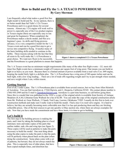
How to Build and Fly <strong>the</strong> ½ A TEXACO POWERHOUSE<br />
By Gary Sherman<br />
I am frequently asked what makes a good first free<br />
flight model to build and fly. In my opinion, <strong>the</strong>re is<br />
no better model than Sal Taibi’s 1/2A Texaco<br />
<strong>Powerhouse</strong> and it is a good choice for several<br />
reasons. Almost any 1/2A engine will work well to<br />
power it, especially any <strong>of</strong> <strong>the</strong> Cox product engines<br />
or Texaco engine (<strong>the</strong>se are especially easy to run<br />
and great for beginners). When completed, <strong>the</strong><br />
<strong>Powerhouse</strong> makes a docile model, and flies at a<br />
beginner’s pace. As skills and flying prowess<br />
advance, it is a very competitive model for <strong>the</strong> ½ A<br />
Texaco event and can be a good first step to get a<br />
novice into competitive flying. It teaches many <strong>of</strong><br />
<strong>the</strong> basic building skills needed to continue in <strong>the</strong><br />
hobby. These reasons (along with <strong>the</strong> fact that <strong>the</strong>y<br />
all seem to fly well) make <strong>the</strong> ½ A <strong>Powerhouse</strong> a<br />
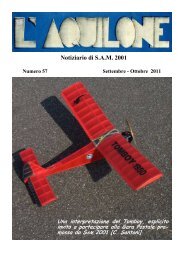
Figure 1 shows a completed 1/2 A Texaco <strong>Powerhouse</strong><br />
great choice. We want new flyers to be successful,<br />
and <strong>the</strong> <strong>Powerhouse</strong> is a great platform to ensure that happens.<br />
The ½ A Texaco event has no minimum weight requirements (like many <strong>of</strong> <strong>the</strong> o<strong>the</strong>r free flight events – I.E. most oldtimer<br />
free flight events have a minimum weight <strong>of</strong> 8 ounces per square foot <strong>of</strong> wing area). That means you can build as<br />
light or as heavy as you want. Because <strong>the</strong>re is a limited amount <strong>of</strong> power available from a reed valve Cox .049 engine,<br />
keeping <strong>the</strong> model fairly light is a definite plus. The ½ A <strong>Powerhouse</strong> has a wing area <strong>of</strong> 540 square inches and can be<br />
built light, with a low wing loading. . There are a lot <strong>of</strong> trade <strong>of</strong>fs regarding weight and I try to put strength where needed,<br />
and save weight where I can, within reason.<br />
Getting Started<br />
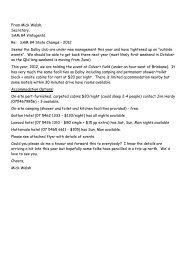
First <strong>of</strong> all, I order a plan. The ½ A <strong>Powerhouse</strong> plan is available from several sources, but we buy from Allen Heinrich<br />
<strong>of</strong> Aerodyne. You can find Aerodyne at, 17244 Darwin, unit C, Hesperia, California 92345. His contact phone number is<br />
(760) 956-2949 and his E-mail is AerodyneAl@aol.com. Aerodyne is a part time business, so call before going <strong>the</strong>re.<br />
Since this is a model that was published in <strong>the</strong> 1930’s, a copy <strong>of</strong> <strong>the</strong> original article is available from <strong>Society</strong> <strong>of</strong> <strong>Antique</strong><br />
<strong>Modelers</strong> (S.A.M.) Librarian Gene Wallock for a fee <strong>of</strong> $2.00. You can order <strong>the</strong> copy <strong>of</strong> <strong>the</strong> original construction article<br />
from Mr. Wallock at: Gene Wallock, 13 Sandy Trail Lane, Lawton, Oklahoma 73505. I usually do this first to look over<br />
construction methods and make sure I really want to build <strong>the</strong> model. Find a nice Cox reed valve engine. It is hard to<br />
believe, but <strong>the</strong>y are actually becoming more collectable now that Cox has quit producing <strong>the</strong>m and <strong>the</strong>y are fetching<br />
collectible prices. One <strong>of</strong> <strong>the</strong> best sources to get one quickly is Ebay auction site, where <strong>the</strong>re are always examples for<br />
sale. Now that you have made <strong>the</strong> commitment and have <strong>the</strong>se items, it is time to get to building.<br />
Let’s build it<br />
The first step in <strong>the</strong> building process is making <strong>the</strong><br />
parts, and I start by taking <strong>the</strong> building plan to a local<br />
stationary store and make copies <strong>of</strong> <strong>the</strong> parts that<br />
outline rudder, stab, ribs and wing tips (see figure 2).<br />
These copies will be used as patterns to make <strong>the</strong> parts<br />
necessary to build <strong>the</strong> model. One neat thing about<br />
using <strong>the</strong> plan copies to make <strong>the</strong> parts is that <strong>the</strong> parts<br />
will fit perfectly when placed back on <strong>the</strong> plan (when<br />
doing <strong>the</strong> construction). Some plans come with a set<br />
<strong>of</strong> patterns, but beware; <strong>the</strong>y do not always match <strong>the</strong><br />
plan. This is especially true <strong>of</strong> older plans, that have<br />
been copied multiple times, and distortion has<br />
Figure 2 Shows copy <strong>of</strong> rudder outline
occurred. It is always a good idea to look over a plan and make sure everything looks correct. Make sure <strong>the</strong> wing will fit<br />
<strong>the</strong> wing saddle; <strong>the</strong> stab fits properly on <strong>the</strong> fuselage, etc.<br />
Do a take-<strong>of</strong>f <strong>of</strong> <strong>the</strong> wood supplies that will be needed. The necessary balsa can be purchased from several balsa<br />
suppliers. I always order more than I need so I can pick <strong>the</strong> weight <strong>of</strong> <strong>the</strong> wood I want for a particular part. There is a<br />
selection <strong>of</strong> light wood known as “Contest Wood” and this should be used in several areas to save weight and help later<br />
with <strong>the</strong> Center <strong>of</strong> Gravity. This will be explained more later, but most models tend to come out tail heavy, so building a<br />
light rudder and stab will help this.<br />
Now that you have your copies made and your supply <strong>of</strong> balsa<br />
wood, you can start making <strong>the</strong> parts. Start by cutting out <strong>the</strong><br />
parts <strong>of</strong> <strong>the</strong> copies.<br />
Then, using a<br />
temporary type<br />
glue stick put some<br />
glue on <strong>the</strong> back<br />
side <strong>of</strong> <strong>the</strong> paper<br />
and paste <strong>the</strong>m<br />
onto <strong>the</strong> proper<br />
thickness and<br />
weight <strong>of</strong> wood<br />
Figure 3 Gluing back <strong>of</strong> pattern<br />
Figure 4 Line up grain and paste pattern to wood<br />
(see figure 3).<br />
Temporary glue sticks are available at most stationery stores. Most <strong>of</strong> <strong>the</strong><br />
plans show <strong>the</strong> direction <strong>the</strong> grain on <strong>the</strong> wood should go, and it is important to pay attention to this as you paste your<br />
patterns on (see figure 4). I make all <strong>the</strong> perimeter parts out <strong>of</strong> contest wood. Contest wood is classified as 6 pound or<br />
less per cubic foot. Using some basic math, and a good scale, you can calculate <strong>the</strong> “poundage” <strong>of</strong> all <strong>the</strong> wood you will<br />
use. The reason I use light wood on <strong>the</strong>se parts is because <strong>the</strong>y are thick enough, that <strong>the</strong>y do not need <strong>the</strong> strength <strong>the</strong><br />
heavier wood might add. Again, saving weight where you can is always advisable.<br />
Once you have your paper pattern pasted<br />
to <strong>the</strong> wood, you may want to stack<br />
more than one part under <strong>the</strong> pattern.<br />
Things like wing tips require two <strong>of</strong><br />
each part, so by stacking <strong>the</strong>m, you can<br />
make two at a time. You can ei<strong>the</strong>r put<br />
a tiny bit <strong>of</strong> CA glue between <strong>the</strong> parts<br />
(very little so <strong>the</strong>y can be separate later),<br />
or use a straight pin through both (see<br />
figure 5). Rough cut <strong>the</strong> parts around<br />
<strong>the</strong> patterns and leave enough so <strong>the</strong>y<br />
Figure 5 cutting a second stacked part can be sanded to <strong>the</strong> final fit. I use our<br />
scroll saw to cut out <strong>the</strong> parts. It<br />
helps a lot to have a scroll saw, but<br />
<strong>the</strong> parts could also be cut out with Figure 6 sanding inside radius<br />
an X-acto knife or a sharp single<br />
edge razor blade. I think it is much<br />
safer, faster and precise to use a scroll saw. Mine is a Makita brand and I<br />
bought it at a local hardware store for under $100. Once <strong>the</strong> parts are<br />
rough cut out, <strong>the</strong>y can be sanded. You can hand sand <strong>the</strong>m, but I prefer to<br />
use a stationary belt sander which I also purchased from <strong>the</strong> local<br />
hardware. It has <strong>the</strong> advantages <strong>of</strong> keeping <strong>the</strong> parts square, and saving a<br />
lot <strong>of</strong> time. I also utilize <strong>the</strong> round top portion <strong>of</strong> <strong>the</strong> sander to do inside<br />
Figure 7 handy disc sander<br />
radiuses (see figure 6). One <strong>of</strong> <strong>the</strong> handiest tools I have for making parts is<br />
a small disc sander. It was custom made, and <strong>the</strong> exact type is no longer<br />
available. Similar precision disc sanders can be had. It is also very handy all through construction (see figure 7).
One <strong>of</strong> <strong>the</strong> best things to come along in a while to add a lot <strong>of</strong> strength,<br />
but not a lot <strong>of</strong> weight is carbon fiber, and I do utilize it in certain<br />
applications. I like to apply a little medium CA glue, and rub <strong>the</strong><br />
carbon down with a paper towel to set <strong>of</strong>f <strong>the</strong> glue and get a good<br />
bond. Refer to figure 8 which shows me making a laminated spar for<br />
<strong>the</strong> <strong>Powerhouse</strong> stab. The carbon is placed on one side <strong>of</strong> <strong>the</strong> spar, and<br />
<strong>the</strong>n <strong>the</strong> o<strong>the</strong>r side <strong>of</strong> <strong>the</strong> spar is placed over <strong>the</strong> top, sandwiching <strong>the</strong><br />
carbon. This is done by using ½ <strong>the</strong> thickness <strong>of</strong> <strong>the</strong> wood shown on<br />
<strong>the</strong> plan. In example, if <strong>the</strong> plan calls for a 1/8 spar (as is <strong>the</strong> case <strong>of</strong><br />
<strong>the</strong> ½ A <strong>Powerhouse</strong> stab which is 1/8” x 1/2”), using <strong>the</strong> carbon built<br />
up spar, use 1/16” balsa, carbon, and ano<strong>the</strong>r 1/16” balsa. The carbon<br />
I use is a unidirectional carbon, .007” thick. I purchase it from<br />
Figure 8 building a carbon laminated spar<br />
Aerospace Composite Products, web site:<br />
http://www.acp-composites.com/ACP-CAT.HTM but it can also be ordered from several o<strong>the</strong>r sources including many<br />
model hobby suppliers. By being unidirectional, it is very stiff in one direction, and is ideal for this type <strong>of</strong> application. I<br />
glue about 6 inches at a time and wipe it down with a paper towel until it kicks <strong>the</strong> glue, and <strong>the</strong>n lift <strong>the</strong> carbon and do<br />
ano<strong>the</strong>r 6 inches. This works great and is much easier than trying to glue <strong>the</strong> entire piece at once. Towards <strong>the</strong> end <strong>of</strong><br />
wiping <strong>the</strong> glue, a shot <strong>of</strong> CA kicker and more wiping will ensure <strong>the</strong> glue is fully cured. Because <strong>the</strong> <strong>Powerhouse</strong> stab<br />
only has one spar, this lamination will help keep it from wanting to warp upward when <strong>the</strong> covering is applied. The stab<br />
is supposed to be flat on <strong>the</strong> bottom, and sanded to an airfoil on top. The covering tends to pull <strong>the</strong> flat bottom up like a<br />
truss as <strong>the</strong> covering draws tight.<br />
Starting assembly<br />
I build right over <strong>the</strong> plan, but only after I apply Saran Wrap or<br />
Wax paper over <strong>the</strong> plan so <strong>the</strong> glue will not stick your parts to<br />
it. Ei<strong>the</strong>r works as a release for <strong>the</strong> parts. If you glue your parts<br />
to <strong>the</strong> plan, you will have a real mess, so be sure to use one <strong>of</strong><br />
<strong>the</strong> above suggested. I like Saran Wrap, while my son prefers<br />
Wax paper. As I said, ei<strong>the</strong>r works fine.<br />
I used thin CA glue for most <strong>of</strong> my building, and apply it<br />
through a Teflon glue tip with a 1/16” outside diameter (Figure<br />
9). These tips can be bought for about $.50 each and <strong>the</strong>re are a<br />
Figure 9 Gluing parts over protected plan<br />
couple styles. One fits right over <strong>the</strong> stock glue bottle tip, and<br />
<strong>the</strong>n some is sold in 1-3 foot sections, and is inserted into <strong>the</strong> end<br />
<strong>of</strong> <strong>the</strong> glue bottle tip. That is <strong>the</strong> type I use, cutting a 1” piece. It is helpful<br />
to cut <strong>the</strong> side that will be inserted into <strong>the</strong> bottle on an angle to get it into<br />
<strong>the</strong> tip easier. By using this tip, it really helps control <strong>the</strong> flow <strong>of</strong> glue.<br />
Usually, only one drop is needed. Without using <strong>the</strong> applicator tip, <strong>the</strong><br />
glue just wants to run out. Try <strong>the</strong>m; you will be glad you did. When <strong>the</strong><br />
part is all built with thin CA and has had time to cure, I pick <strong>the</strong> part up<br />
and re-glue <strong>the</strong> joints<br />
with just a little more thin<br />
or medium CA (Figure<br />
10).<br />
Figure 10 re-gluing joints on rudder <strong>Building</strong> <strong>the</strong> rudder for<br />
<strong>the</strong> <strong>Powerhouse</strong> is pretty<br />
straight forward. The<br />
only modification I make from <strong>the</strong> plan is to add gussets to both side <strong>of</strong><br />
<strong>the</strong> rudder post as is visible in Figure 10. This helps to keep <strong>the</strong> glue<br />
joint solid after covering. Without <strong>the</strong>m, I have seen <strong>the</strong> rudder post<br />
actually crush into <strong>the</strong> bottom <strong>of</strong> <strong>the</strong> rudder, and fail. When <strong>the</strong><br />
assembly is all glued toge<strong>the</strong>r, I remove it from <strong>the</strong> plan and I re-glue<br />
each joint with a small amount <strong>of</strong> medium CA for additional strength. I<br />
Figure 11 sanding rudder flat both sides
only use a small amount, again being conscious <strong>of</strong> <strong>the</strong> overall weight. When dry, I sand both sides to get it flat and <strong>the</strong>n<br />
sand a uniform symmetrical airfoil to <strong>the</strong> leading and trailing edge (see figure 11).<br />
The stabilizer construction is done in much <strong>the</strong> same fashion as <strong>the</strong> rudder.<br />
After I have it built, and have re-glued all <strong>the</strong> joints, I sand <strong>the</strong> bottom <strong>of</strong> it<br />
flat. On <strong>the</strong> stab, a lifting airfoil is sanded on <strong>the</strong> top <strong>of</strong> <strong>the</strong> stab (refer to<br />
plan). When done right, it will have a flat bottom lifting stab.<br />
The first step in building <strong>the</strong> wing is making <strong>the</strong> wing ribs. I use a copy<br />
made from <strong>the</strong> plan<br />
and affix it to a<br />
piece <strong>of</strong> 1/8”<br />
plywood. I <strong>the</strong>n<br />
temporarily glue<br />
ano<strong>the</strong>r 1/8” piece<br />
<strong>of</strong> plywood to <strong>the</strong><br />
Figure 13 drilling holes in roughed out balsa ribs<br />
rough cut (oversize) my balsa ribs and a few at a time, drill <strong>the</strong> 1/8”<br />
holes through <strong>the</strong>m, using one <strong>of</strong> my 1/8” rib templates as a guide<br />
(see figure 13). I can usually stack ½ <strong>of</strong> <strong>the</strong> needed ribs between <strong>the</strong><br />
templates at a time to finish <strong>the</strong>m, making all my ribs in two batches.<br />
With half <strong>the</strong> ribs sandwiched between my two finished templates,<br />
and 1/8” dowels<br />
running through all, I<br />
sand <strong>the</strong> balsa ribs to<br />
<strong>the</strong> shape <strong>of</strong> <strong>the</strong><br />
templates. When that is<br />
done, I am ready to cut<br />
in my spars notches. I<br />
Figure 15 making trailing edge<br />
Figure 12 <strong>the</strong> start <strong>of</strong> rib templates<br />
first and drill two 1/8” holes through both pieces <strong>of</strong> plywood<br />
(see figure 12). I insert 1/8” dowels in <strong>the</strong> holes to hold all my<br />
ribs between <strong>the</strong> two completed templates and <strong>the</strong> holes will act<br />
as a vent when <strong>the</strong> wing is constructed. I sand and finish <strong>the</strong> two<br />
plywood templates to <strong>the</strong> outline and separate <strong>the</strong>m. Now, <strong>the</strong>y<br />
are ready<br />
to be used<br />
to make<br />
ribs. I<br />
Figure 14 cutting notches for spars<br />
have a Dremel and a Micro-Mark table saw, and both work well for this<br />
operation. Before I had <strong>the</strong> saws, I would cut <strong>the</strong>m in using a Zona saw and<br />
assorted files to get <strong>the</strong>m to <strong>the</strong> correct size. With a table saw, I make several<br />
passes adjusting a little<br />
at a time to get <strong>the</strong><br />
correct notch width (see<br />
figure 14). I also use a<br />
cheap set <strong>of</strong> calipers to<br />
keep checking <strong>the</strong> notch<br />
size. When all <strong>the</strong><br />
notches are cut, I am<br />
ready to repeat <strong>the</strong>se<br />
steps to make <strong>the</strong> o<strong>the</strong>r<br />
batch <strong>of</strong> ribs.<br />
While you can buy <strong>of</strong>f <strong>the</strong> shelf trailing edge, I like to make my own<br />
Figure 16 shows 3/8" balsa tips installed<br />
(see figure 15). This allows me to make it at <strong>the</strong> correct angle to<br />
match my ribs and saves a lot <strong>of</strong> sanding later. I make my wing tip parts out <strong>of</strong> real light 3/8” balsa. This extra thickness
Figure 17 trailing edge is notched for ribs<br />
may add a little<br />
weight, but<br />
makes <strong>the</strong><br />
shape <strong>of</strong> <strong>the</strong> tip<br />
much better<br />
and makes it<br />
much easier to<br />
cover when<br />
completed (see<br />
figure 16). The<br />
tip is glued on<br />
flat, but <strong>the</strong><br />
front <strong>of</strong> <strong>the</strong><br />
trailing edge is<br />
Figure 18 <strong>the</strong> 3/8" tips allow complete shaping<br />
lifted to match <strong>the</strong> curvature <strong>of</strong> <strong>the</strong> rib which is not flat on <strong>the</strong> bottom. When <strong>the</strong> wing tips are glued to <strong>the</strong> wing, note that<br />
<strong>the</strong>y are not flat on <strong>the</strong> plan, but are actually up in <strong>the</strong> air as <strong>the</strong>y are lined up with <strong>the</strong> center <strong>of</strong> <strong>the</strong> leading edge and <strong>the</strong><br />
center <strong>of</strong> <strong>the</strong> trailing edge. This is correct. When<br />
sanding <strong>the</strong> tip to shape (see figure 18) a useful tip is<br />
to put masking tape on <strong>the</strong> ribs so you don’t<br />
accidentally start sanding <strong>the</strong>m away. You use <strong>the</strong><br />
ribs as a guide, but do not want to remove any<br />
material from <strong>the</strong>m. Also note in figure 18 how <strong>the</strong><br />
spars are cut and glued from <strong>the</strong> last rib to <strong>the</strong> tip.<br />
The wing’s center ribs are cut down 1/16” on top and<br />
bottom. This area is to be sheeted with 1/16” medium<br />
weight balsa. In <strong>the</strong> last few years, I have been<br />
utilizing .007 unidirectional carbon fiber at my<br />
dihedral joints as doublers (see figure 19). I have had<br />
real good luck with this method and it is very light.<br />
Using plywood or hard balsa doublers will work okay<br />
Figure 19 shows carbon fiber doublers for <strong>the</strong> spar joints<br />
too, but is a little heavier. The spars in <strong>the</strong> wing are<br />
picked and matched for weight. I try to use a medium<br />
weight <strong>of</strong> 8-12 pounds for <strong>the</strong> wing spars. It is important to match <strong>the</strong> weight and strength <strong>of</strong> <strong>the</strong> spars for <strong>the</strong> balance <strong>of</strong><br />
<strong>the</strong> wing and for <strong>the</strong> longevity <strong>of</strong> it. While <strong>the</strong> wing does not have to be as strong as those on bigger and faster models, it<br />
does have to be strong enough to<br />
withstand <strong>the</strong> impact <strong>of</strong><br />
de<strong>the</strong>rmalizing.<br />
Figure 20 wing on my hinging dihedral jig<br />
The <strong>Powerhouse</strong> has a flat center<br />
section, and both wing panels are<br />
attached at <strong>the</strong> appropriate angel<br />
and glued to <strong>the</strong> carbon doublers as<br />
well as in <strong>the</strong> butt-joint as shown in<br />
figure 19 and 20. I have made a<br />
special hinging board to set <strong>the</strong><br />
dihedral joints. Not only does this<br />
allow me to set <strong>the</strong> angle correctly,<br />
it also ensures that <strong>the</strong> wing remains<br />
straight and that <strong>the</strong> wing panels are<br />
not sweeping forward or back. The<br />
jig is made with a piano hinge and<br />
5/8” birch plywood (figure 20). I<br />
just use whatever is handy to space<br />
it up to <strong>the</strong> correct angle.
The Fuselage on <strong>the</strong> <strong>Powerhouse</strong> is a<br />
basic box frame construction. To get<br />
started, I weigh and find four<br />
medium/hard balsa longerons, 12-14 lb.<br />
wood. By matching <strong>the</strong> strength and<br />
weight <strong>of</strong> <strong>the</strong> longerons, <strong>the</strong> fuselage will<br />
build more uniform and will be strong.<br />
Balsa, weight and strength do tend to go<br />
hand-in-hand. If you did not take <strong>the</strong> time<br />
to match your longerons, <strong>the</strong> weakest will<br />
bend <strong>the</strong> easiest, and <strong>the</strong> strongest will try<br />
to go back to <strong>the</strong> natural straight shape.<br />
This will cause <strong>the</strong> fuselage to be shaped<br />
like a banana, which is not what we are<br />
looking for.<br />
Pin down <strong>the</strong> longerons and start making<br />
your cross pieces. For this, I use my disc<br />
sander get <strong>the</strong> final size, and make two<br />
parts at a time so when I am ready to build<br />
Figure 22 One side glued up<br />
Figure 21 shows one fuselage side on plan, note calipers, scale & angle finder<br />
Figure 23 sanding both sides flat<br />
<strong>the</strong> second half, I already have all <strong>the</strong> pieces made<br />
and <strong>the</strong>y are exactly <strong>the</strong> same as <strong>the</strong> first side.<br />
Figure 21 shows my first side made and <strong>the</strong> extra<br />
corresponding part for <strong>the</strong> second side above <strong>the</strong><br />
first side. I start making my cross pieces<br />
(diagonals) in <strong>the</strong> front where <strong>the</strong>y are <strong>the</strong> longest.<br />
If I make a mistake and one gets too short, I simply<br />
use it for <strong>the</strong> next smallest part. The parts get<br />
smaller as you work towards <strong>the</strong> back. When all <strong>the</strong><br />
diagonals are glued and <strong>the</strong> sheeting for <strong>the</strong> engine<br />
cheek is glued in place, I again lift <strong>the</strong> side <strong>of</strong>f <strong>the</strong><br />
plan and go over <strong>the</strong> joints with a little medium CA<br />
glue (see figure 22). Build <strong>the</strong> o<strong>the</strong>r side following<br />
<strong>the</strong> same steps and <strong>the</strong>n sand both <strong>of</strong> <strong>the</strong> sides flat<br />
Figure 24 sanding <strong>the</strong> corner <strong>of</strong> <strong>the</strong> windows round<br />
(see figure 23). I use a drum sander to sand <strong>the</strong><br />
curves in <strong>the</strong> corner <strong>of</strong> <strong>the</strong> window frame (see figure<br />
24). This makes for a nice looking curve, very<br />
uniform. I sometimes will also make sanders, by wrapping sand paper around tubes for sanding similar inside radius.
The front <strong>of</strong> <strong>the</strong> cabin, where <strong>the</strong>re is an upright, is a weak<br />
spot because <strong>the</strong> upright is bisected by <strong>the</strong> bottom outline<br />
<strong>of</strong> <strong>the</strong> window. To add strength in this area, I glue a piece<br />
<strong>of</strong> .007 thick unidirectional carbon fiber full height. This<br />
helps support <strong>the</strong> joint, and I have never had one break<br />
since using this method. You can also add ano<strong>the</strong>r<br />
upright, full height, to <strong>the</strong> inside where <strong>the</strong> carbon is glued<br />
in figure 25. Remember you are making a left and right<br />
side, so be conscious to glue <strong>the</strong> support to <strong>the</strong> correct side<br />
on each fuselage side.<br />
I am now ready to join <strong>the</strong> two halves. I start at <strong>the</strong> front<br />
Figure 25 carbon fiber added for strength on upright<br />
where <strong>the</strong> fuselage cross pieces are all <strong>the</strong> same length and<br />
make eight parts exactly <strong>the</strong> same length. I tape one side<br />
to a square, so I am sure it is straight up and down. I<br />
weight <strong>the</strong> sides down to <strong>the</strong> plan using lead weights (see<br />
figure 26). This gets everything square, and<br />
perpendicular. I also do this right over a top view. The<br />
<strong>Powerhouse</strong> plan does actually have a top view, it just<br />
specifies a width. So, I draw a top view on <strong>the</strong> back side<br />
<strong>of</strong> <strong>the</strong> plan, starting with a center line.<br />
With <strong>the</strong> sides rigged as shown in figure 26, I start gluing<br />
Figure 26 joining <strong>the</strong> two fuselage sides<br />
in <strong>the</strong> cross pieces. I glue in <strong>the</strong> bottom and <strong>the</strong> top cross<br />
pieces that I made earlier to <strong>the</strong> same length. After <strong>the</strong>se<br />
are glued in place a dry, I pull <strong>the</strong> sides toge<strong>the</strong>r in <strong>the</strong> back and this creates a natural flowing curvature. I sand <strong>the</strong> inside<br />
<strong>of</strong> both sides a little at <strong>the</strong> back so <strong>the</strong>y can be<br />
lined up and glued toge<strong>the</strong>r. This is where <strong>the</strong><br />
center line is very handy, as <strong>the</strong> back <strong>of</strong> <strong>the</strong><br />
fuselage should line up exactly over <strong>the</strong> center<br />
line when glued toge<strong>the</strong>r. This will ensure a<br />
straight fuselage. Then, I make <strong>the</strong> reaming cross<br />
pieces to fit <strong>the</strong> curvature created by gluing <strong>the</strong><br />
two sides toge<strong>the</strong>r at <strong>the</strong> back. Be sure you do not<br />
sand <strong>the</strong>m too thin at <strong>the</strong> back, as this is where <strong>the</strong><br />
de<strong>the</strong>rmalizer and snuffer (tubing used to snuff<br />
out <strong>the</strong> de<strong>the</strong>rmalizer fuse) tube will be added<br />
later.<br />
The firewall is made from 1/8” aircraft grade<br />
birch plywood. I use a modified countersink drill<br />
for <strong>the</strong> four 4 x 40 blind nuts placed in <strong>the</strong> firewall<br />
to mount my tank (see figure 27). This allows me<br />
to slightly countersink <strong>the</strong> blind nuts in and get<br />
Figure 27 firewall, tank-mount, countersink, blind nuts<br />
good glue joint. I press <strong>the</strong> blind nuts in after<br />
using Super Seam (an adhesive used to attach<br />
covering to metal and wood on full size aircraft) as glue. When it is dry, I go over it again with ano<strong>the</strong>r coat <strong>of</strong> Super<br />
Seam. You want to be sure to get <strong>the</strong>se glued in well, as you never want <strong>the</strong>m to fall out. Super Seam can be purchased<br />
from Aircraft Spruce, 225 Airport Circle, Corona, California, 92882. Their phone number is 951-372-9555. They are a<br />
supplier for home-builts and general aviation. Note <strong>the</strong> ring I added in figure 27. This was done so <strong>the</strong> blind nuts did not<br />
protrude through <strong>the</strong> front <strong>of</strong> <strong>the</strong> firewall when glued in place. Also note, it is <strong>of</strong>fset to <strong>the</strong> side, so <strong>the</strong> prop will be more
centered when we add left thrust. Before gluing<br />
<strong>the</strong> firewall in place, it is always a good idea to<br />
chase <strong>the</strong> threads with a 4 x 40 tap to make sure<br />
no glue got into <strong>the</strong> threads. Sal Taibi used to<br />
make <strong>the</strong> tank mounts like <strong>the</strong> one shown in figure<br />
27, but no longer does. The current SAM rules<br />
allow for 15cc <strong>of</strong> fuel, but <strong>the</strong> rule cycle is due to<br />
be voted on again, and <strong>the</strong>re is a movement to go<br />
to 8cc (<strong>the</strong> size <strong>of</strong> a stock Cox Texaco tank). It is<br />
beneficial to run a tank-mount as shown. It spaces<br />
<strong>the</strong> engine out to <strong>the</strong> proper location (without it, a<br />
spacer will have to be made to get <strong>the</strong> engine<br />
where it needs to be). Getting <strong>the</strong> engine in <strong>the</strong><br />
proper location will really help with balancing<br />
your model as <strong>the</strong>y almost always come out tail<br />
heavy. Cox engines have an o-ring in <strong>the</strong>m that is<br />
in <strong>the</strong> middle <strong>of</strong> <strong>the</strong> tank. When <strong>the</strong> tank is full,<br />
<strong>the</strong> o-ring is submerged in fuel. When it gets<br />
down to a half tank, it starts to be surrounded by<br />
air. Many times, this will leak and cause your<br />
engine to lean and only run ½ <strong>the</strong> tank and <strong>the</strong><br />
engine will stop.<br />
I bend <strong>the</strong> landing gear and glue it up between<br />
balsa sheet wood. When completed, <strong>the</strong><br />
sandwiched gear should line up with <strong>the</strong> fuselage<br />
uprights, where it can be secured well (see figure<br />
28).<br />
The hood (part that fits behind <strong>the</strong> engine is<br />
formed by wetting a piece <strong>of</strong> 1/16” balsa and<br />
taping it around a cylinder. I used a can <strong>of</strong> spray<br />
paint to wrap mine around, and secured it using<br />
masking tape until dry (see figure 29). By<br />
Figure 29 <strong>the</strong> formed hood for <strong>the</strong> <strong>Powerhouse</strong><br />
performing this part, it will take <strong>the</strong> bind out <strong>of</strong> it<br />
for fitting and is much less likely to crack later. I<br />
soak <strong>the</strong> wood in water, but some prefer to add a little ammonia to <strong>the</strong><br />
water thinking it helps with <strong>the</strong> bending process. I have had good luck<br />
with just using water, and don’t have to smell <strong>the</strong> ammonia. Ei<strong>the</strong>r will<br />
work. When it is dry, I fit it and glue it to <strong>the</strong> fuselage. The nose block<br />
under <strong>the</strong> engine can be fit and glued on now using medium balsa. Make<br />
sure you can reach all <strong>the</strong> screws that hold <strong>the</strong> tank to <strong>the</strong> firewall. About<br />
<strong>the</strong> last thing to add is <strong>the</strong> sun visor. After shaping and sanding <strong>the</strong> nose<br />
cowl blow out <strong>the</strong> dust and fuel pro<strong>of</strong> <strong>the</strong> inside area. I use slow drying<br />
epoxy thinned a little with lacquer thinner. A little thinner goes a long way.<br />
I mix and brush it on with an acid brush, being careful not to get any in <strong>the</strong><br />
blind nuts. It may take a few days to dry. A warm climate or room helps. I<br />
<strong>the</strong>n sand this area <strong>the</strong> best I can and brush on ano<strong>the</strong>r coat. This makes a<br />
shiny and smooth fuel-pro<strong>of</strong> engine area.<br />
COVERING WITH POLY SPAN<br />
I cover all my gas models with Polyspan as it is light and provides a<br />
strong, long-lasting finish. I also like how stable it is. Since it is a<br />
polyester base material, it is not affected by moisture like many <strong>of</strong> <strong>the</strong><br />
o<strong>the</strong>r coverings, like silk, or tissue. Polyspan is excellent and helps you<br />
have that consistent model you are looking for, with no surprise warps<br />
Figure 28 shows landing gear in place<br />
Figure 30 brushing on sanding sealer
showing up. Polyspan has a smooth side and a<br />
rougher side, where <strong>the</strong> fibers stick up. It is very hard<br />
to see <strong>the</strong> difference, but <strong>the</strong> smooth side is a little<br />
shinier, and with careful inspection, you can see <strong>the</strong><br />
fibers on <strong>the</strong> rough side. The smooth, shiny side goes<br />
out and is <strong>the</strong> finish side. As <strong>of</strong> now, <strong>the</strong> only color<br />
that Polyspan comes in is white (natural).<br />
To prepare <strong>the</strong> surfaces to be covered, I make sure all<br />
are sanded smooth and are blown clean. I brush on a<br />
coat <strong>of</strong> lacquer sanding sealer (see figure 30)<br />
everywhere <strong>the</strong> covering will contact <strong>the</strong> structure.<br />
That means <strong>the</strong> top and bottom <strong>of</strong> ribs, all <strong>the</strong><br />
perimeters, etc. I finish exclusively with nitrate dope,<br />
and have found <strong>the</strong> lacquer sanding sealer to be<br />
compatible. If you plan to use an alternative finish,<br />
make sure everything is compatible by making a test<br />
panel. After my sanding sealer is dry, I sand all <strong>the</strong><br />
surfaces with 220-320 grit paper and again blow <strong>the</strong><br />
surface clean with compressed air. I <strong>the</strong>n add a second<br />
coat <strong>of</strong> sanding sealer and sand it with 320 paper. You<br />
will notice <strong>the</strong> second coat will sand much easier and<br />
you will have a very smooth surface. Blow <strong>the</strong> dust<br />
<strong>of</strong>f <strong>the</strong> structure.<br />
There are a few products that can be used to attach <strong>the</strong><br />
covering to <strong>the</strong> surface, but I have been using Fab Tac<br />
also available from Aircraft Spruce (contact<br />
information noted previously in this article). The<br />
Super Seam used to glue in <strong>the</strong> blind nuts works great<br />
too. I have found <strong>the</strong> Fab Tac works just as well as <strong>the</strong><br />
Super Seam, and is about half <strong>the</strong> price. Both products<br />
need to be thinned a lot using Nitrate thinner to get to<br />
brushing consistency.<br />
I brush on two coats <strong>of</strong> thinned Fab Tac<br />
over all <strong>the</strong> areas I used <strong>the</strong> lacquer sanding<br />
sealer on (where <strong>the</strong> covering will contact<br />
<strong>the</strong> framework). It dries fast, so you will<br />
have to work fast. Make sure to let it dry<br />
fully between coats. When both coats are<br />
dried, I make sure <strong>the</strong>re are no defects in it<br />
like a run. If I find a defect, I lightly sand<br />
that area, and clean with compressed air.<br />
Now, I am ready to cover.<br />
I usually start with <strong>the</strong> bottom <strong>of</strong> <strong>the</strong> stab. It<br />
is always correct to cover from <strong>the</strong> bottom<br />
to <strong>the</strong> top on all parts. The flat surfaces are<br />
very easy to do. Do not forget <strong>the</strong> fuzzy<br />
side goes towards <strong>the</strong> frame work, and <strong>the</strong><br />
smooth side out. Cut your Polyspan larger<br />
than <strong>the</strong> area to be covered. You want extra<br />
material to hold onto around <strong>the</strong> perimeter if<br />
heating is necessary to get it smooth.<br />
Figure 31 covering on wing tip, note wrinkles<br />
Figure 32 covering attached to spar with Acetone<br />
Figure 33 covering attached between wrinkles from extra covering
Figure 33 again shows wrinkle to be shrunk with heat<br />
Polyspan can be stretched and shrunk with heat and<br />
will go around some severe compound curves. To<br />
attach <strong>the</strong> covering, lay it over <strong>the</strong> structure and use<br />
Acetone in a brush to activate <strong>the</strong> Fab Tac on <strong>the</strong><br />
framework. By brushing <strong>the</strong> Acetone through <strong>the</strong><br />
covering, it will s<strong>of</strong>ten and activate <strong>the</strong> Fab Tac, and<br />
will adhere quite quickly. Try to work out as many<br />
wrinkles as possible as you are attaching <strong>the</strong> Polyspan.<br />
For purposes <strong>of</strong> showing <strong>the</strong> stretching and shrinking<br />
capability <strong>of</strong> Polyspan, I will show <strong>the</strong> top <strong>of</strong> <strong>the</strong><br />
<strong>Powerhouse</strong> wing tip (figures 31-34). I attach <strong>the</strong><br />
covering at <strong>the</strong> root, and <strong>the</strong>n pull it and attach it<br />
down <strong>the</strong> spar (see figure 32). Because <strong>the</strong> tip is a<br />
compound curve, <strong>the</strong>re is an excess <strong>of</strong> material<br />
when you start attaching it around <strong>the</strong> perimeter.<br />
The way I do this is to pull it and attach it in small<br />
sections, leaving <strong>the</strong> excess material in between<br />
several points where I attach it (see figure 33). I use<br />
a MonoKote heat gun to shrink <strong>the</strong> material between<br />
<strong>the</strong> points <strong>of</strong> attachment (see figure 34). Make sure<br />
you let <strong>the</strong> Acetone gas out before doing this (dry),<br />
or it will bubble <strong>the</strong> Fab Tac as <strong>the</strong> Acetone is<br />
heated. I go one wrinkle at a time, and after it is<br />
Figure 36 sanding <strong>of</strong>f <strong>the</strong> extra covering<br />
Figure 34 I use a MonoKote heat gun to shrink out wrinkles<br />
Figure 35 a completed wing tip shrunk and attached<br />
shrunk down smooth, I attach it with Acetone. Now you can see<br />
why I cut <strong>the</strong> Polyspan oversize so I do not get burned when<br />
shrinking. One useful tip is to start shrinking <strong>the</strong> material<br />
outside <strong>the</strong> framework and work inward. By working one<br />
wrinkle at a time, I get a very nice finish on my compounding<br />
curves (see figure 35). I like to attach around <strong>the</strong> perimeter and<br />
shrink all <strong>the</strong> covering over <strong>the</strong> surface before attaching to <strong>the</strong><br />
ribs. Make sure you stick it well to <strong>the</strong> bottom ribs, where <strong>the</strong>re<br />
is under camber. Here, I will hold it against <strong>the</strong> camber with my<br />
fingers until <strong>the</strong> Acetone dries, which only takes a few seconds.
Also, make sure it is attached to <strong>the</strong> top <strong>of</strong> <strong>the</strong> ribs and all spars.<br />
After <strong>the</strong> covering is attached to <strong>the</strong> perimeters, ribs, and spars, I roll up a piece <strong>of</strong> 320 wet-or-dry sandpaper and use it to<br />
trim <strong>of</strong>f <strong>the</strong> excess covering (see figure 36). Make sure you have allowed adequate time for <strong>the</strong> Fab Tac and Acetone to<br />
dry before doing this.<br />
Whenever Polyspan is lapped over itself, like at <strong>the</strong> dihedral joints <strong>of</strong> <strong>the</strong> wing, brush on two coats <strong>of</strong> Fab Tac over <strong>the</strong><br />
first layer where it will be overlapped by <strong>the</strong> second layer. This will ensure a good positive joint, and <strong>the</strong> covering will<br />
not split away. I also use full strength Fab Tac or Super Seam to attach <strong>the</strong> rudder to <strong>the</strong> stab after both are covered. It<br />
makes a good joint as both glues are designed to glue fabric to wood or metal, so it is <strong>the</strong> best choice.<br />
After finishing <strong>the</strong> wing<br />
covering, I drill a small hole<br />
through <strong>the</strong> center section<br />
sheeting (bottom) to vent <strong>the</strong><br />
wing. Remember <strong>the</strong> holes in<br />
<strong>the</strong> ribs that were made<br />
during <strong>the</strong> scratch building<br />
process? Well now <strong>the</strong>y act<br />
as vents and allow <strong>the</strong> wing to<br />
vent tip to tip. Without a<br />
vent, <strong>the</strong> wing would tend to<br />
blow up like a balloon when<br />
put in <strong>the</strong> sun at <strong>the</strong> flying<br />
field. Venting adds to <strong>the</strong><br />
stability <strong>of</strong> <strong>the</strong> covering and it<br />
is much less-likely to warp by<br />
doing this. On <strong>the</strong> rudder<br />
and stab, I use a straight pin<br />
to poke small holes (on <strong>the</strong><br />
bottom <strong>of</strong> stab, and one side<br />
<strong>of</strong> rudder) in <strong>the</strong> corners <strong>of</strong><br />
Figure 37 heat is used around all compound curves, like <strong>the</strong> front <strong>of</strong> fuselage<br />
<strong>the</strong> structure to vent <strong>the</strong>m as<br />
well. Like I said, this is a<br />
very important step in <strong>the</strong><br />
covering process. Remember, heat can be used to stretch and shrink Polyspan, and <strong>the</strong> heat will help you achieve a good<br />
covering job over all compound surfaces (see Figure 37).<br />
Applying <strong>the</strong> Nitrate Dope<br />
When all <strong>the</strong> covering is attached and shrunk tight with a heat gun, I am ready to apply my nitrate dope. There<br />
are two types <strong>of</strong> Nitrate dope, standard (tautening) which means it draws tight as it cures, and non-tautening<br />
which does not draw as it cures. Be cautious in using too much standard dope especially on a light structure<br />
where it can actually cause crushing and severe distortion. Most dopes are thinned 50/50 with nitrate thinner<br />
to get a good brushing consistency. I use a specific brand <strong>of</strong> foam brush to apply <strong>the</strong> dope, a 3” wide Jen (brand<br />
name is Jen) brush. It says not for use with lacquers, but works great as long as <strong>the</strong> entire brush is not<br />
submerged in <strong>the</strong> thinned dope. I only wet about <strong>the</strong> last 1” – 1 ¼” <strong>of</strong> <strong>the</strong> brush in <strong>the</strong> dope.<br />
I start by applying a coat <strong>of</strong> standard (tautening) dope over <strong>the</strong> entire covered area. This helps keep <strong>the</strong><br />
covering tight. I <strong>the</strong>n put a second coat <strong>of</strong> standard on <strong>the</strong> bottom <strong>of</strong> <strong>the</strong> wing. The wing and stab tend to want<br />
to warp up, as <strong>the</strong> airfoil acts a truss, and pulls against <strong>the</strong> bottom which is flat or near flat. When completed, I<br />
apply 4-5 coats <strong>of</strong> clear nitrate. On <strong>the</strong> bottom <strong>of</strong> <strong>the</strong> stab, I use all standard nitrate. All <strong>the</strong> o<strong>the</strong>r coats, except<br />
those noted, are done with non-tautening. I move <strong>the</strong> brush slowly, and do not apply a lot <strong>of</strong> pressure.<br />
Remember, you are trying to apply <strong>the</strong> dope, not squeeze a bunch through <strong>the</strong> covering. This will only add<br />
unnecessary weight. As you start getting dope built up, you may notice <strong>the</strong> brush grabbing on <strong>the</strong> leading edge
and trailing edge. If this happens, you can sand those areas with 400 sandpaper. DO NOT sand <strong>the</strong> Polyspan<br />
between coats, as it will only pull fibers up and mess up <strong>the</strong> finish. After your 4-5 coats <strong>of</strong> dope are applied,<br />
you can very lightly sand <strong>the</strong> surface if you want but it is not necessary. If you want to put your AMA number<br />
or o<strong>the</strong>r decorative tissue on your model, apply it after 3 coats <strong>of</strong> dope, and put at least 3 coats over <strong>the</strong> top <strong>of</strong><br />
your tissue to seal it as well.<br />
I cut my letters from Japanese tissue. I use 3M fine Line<br />
tape as a reference and hold <strong>the</strong>m in place with a pair <strong>of</strong><br />
tweezers and spray <strong>the</strong>m with water, one at a time. Now<br />
final position it and blot out as much water as possible<br />
with a paper towel. As soon as I am finished blotting, I<br />
start brushing on a little acetone. The acetone keeps <strong>the</strong><br />
letter locked down until water evaporates. Keep it<br />
acetone wet until all <strong>of</strong> <strong>the</strong> water has evaporated. Repeat<br />
this process with all your letters. As you become more<br />
pr<strong>of</strong>icient, you can start doing several letters at a time.<br />
The <strong>Powerhouse</strong> decals on <strong>the</strong> side <strong>of</strong> <strong>the</strong> fuselage were<br />
scanned from an old article and made on <strong>the</strong> computer.<br />
Wire Fittings and dowels<br />
Some hardware is necessary now, like <strong>the</strong> wing and<br />
stabilizer keys, <strong>the</strong> de<strong>the</strong>rmalizer hooks, and <strong>the</strong> snuffer<br />
tube (See figure 38). The two wires with <strong>the</strong> large radius<br />
are for <strong>the</strong> top <strong>of</strong> <strong>the</strong> stab, and <strong>the</strong> large radius is<br />
intentional to get more leverage to pop up <strong>the</strong> stab in<br />
de<strong>the</strong>rmalizer mode. The o<strong>the</strong>r two wires go on <strong>the</strong> back<br />
<strong>of</strong> <strong>the</strong> stab and <strong>the</strong> back <strong>of</strong> <strong>the</strong> fuselage. This is where I<br />
wrap a rubber band around <strong>the</strong> de<strong>the</strong>rmalizer fuse. The<br />
snuffer tube also goes in <strong>the</strong> back <strong>of</strong> <strong>the</strong> fuselage, between<br />
<strong>the</strong> two wires. The wing and stab keys are made from ½<br />
round made from dowel. I like to round <strong>the</strong> ends also as I<br />
think it looks better. I glue <strong>the</strong> wires and alignment keys<br />
with Fab Tac, at near full strength.<br />
Now cut <strong>the</strong> 3/16” dowels <strong>the</strong> rubber bands loop around to<br />
hold <strong>the</strong> wing and stab to <strong>the</strong> fuselage. They should stick<br />
out <strong>of</strong> <strong>the</strong> fuselage about 5/8” on each side. Make sure<br />
your wing is square before gluing <strong>the</strong> keys on. Put <strong>the</strong><br />
wing on with some #64 rubber bands, and measure from<br />
<strong>the</strong> tail to a spot on <strong>the</strong> wing tip on both sides. If <strong>the</strong><br />
measurements are <strong>the</strong> same, <strong>the</strong> wing <strong>the</strong> wing should be<br />
square to <strong>the</strong> fuselage and you can glue on your keys.<br />
Next, glue <strong>the</strong> four dowels to <strong>the</strong> bottom <strong>of</strong> <strong>the</strong> stab (with<br />
stab installed). Don’t forget, <strong>the</strong> rudder is supposed to be<br />
<strong>of</strong>fset for glide turn.<br />
Figure 38 shows <strong>the</strong> de<strong>the</strong>rmalizer hooks, wing keys and<br />
snuffer tube. Also, I make a hole-saw out <strong>of</strong> brass tube to drill<br />
wing hold-down dowel holes<br />
Figure 39 one side <strong>of</strong> fuselage masked as described with 3M<br />
Fine Line and 3M Scotch 233+ masking tape. Works great!<br />
Now for <strong>the</strong> Paint<br />
I really like <strong>the</strong> looks <strong>of</strong> <strong>the</strong> <strong>Powerhouse</strong> paint scheme, and have followed it on each <strong>of</strong> <strong>the</strong>m I have built. To get nice<br />
sharp lines, I mask <strong>the</strong> paint scheme with 3M Scotch Fine Line (a tan colored product). It is available in many widths,<br />
conforms to sharp corners, and sticks well. It is very good to stop bleed under, where paint bleeds under <strong>the</strong> tape, and<br />
leaves a s<strong>of</strong>t edge. After I have <strong>the</strong> outline <strong>of</strong> <strong>the</strong> paint scheme down with Fine Line, I use newspaper and 3M 233+<br />
(green) masking tape to cover <strong>the</strong> areas I do not want painted (refer to figures 39 and 40). Both products were developed<br />
for <strong>the</strong> automotive paint industry and are resistant to chemicals like thinner and most types <strong>of</strong> paint. If you use <strong>the</strong> wrong<br />
type <strong>of</strong> masking tape, you will run <strong>the</strong> risk <strong>of</strong> it lifting as soon as <strong>the</strong> paint hits it, or maybe worse, <strong>the</strong> adhesive being<br />
attacked and becoming a permanent part <strong>of</strong> your model by not being able to peel it <strong>of</strong>f! In any case, I have found <strong>the</strong>
233+ to be <strong>the</strong> best masking tape available. These 3M masking products can be purchased from any automotive paint<br />
supplier. A tip on using <strong>the</strong> newspaper is to use two layers in case <strong>the</strong>re is an imperfection. This will eliminate paint<br />
getting where you do not want<br />
it. Also note, one side always<br />
has small holes used in <strong>the</strong><br />
printing process so be sure to<br />
tape over <strong>the</strong>m, or not use that<br />
side where possible. After<br />
everything is masked and<br />
before painting, I always rub<br />
down <strong>the</strong> edges good before<br />
applying color.<br />
Colored Nitrate is almost<br />
impossible to get. The one<br />
source for colored Nitrate is<br />
Aerodyne (Allen Heinrich)<br />
whose contact information was<br />
listed earlier in this article. He<br />
sells a good selection, with<br />
white, black, red, yellow, cream<br />
Figure 40 Fine Line and 233+ masking used on <strong>the</strong> stab as described. Note <strong>the</strong> rudder<br />
<strong>of</strong>fset and how <strong>the</strong> paint scheme is also <strong>of</strong>fset to match<br />
and blue among o<strong>the</strong>r colors. His colors are opaque and cover quite quickly. Many times, I am after a translucent look,<br />
and have had excellent luck mixing House <strong>of</strong> Kolor (ano<strong>the</strong>r automotive paint product) Kandy Koncentrate with thinned<br />
clear dope. When I mix my<br />
colored dope, I always use<br />
non-tautening dope, thinned<br />
to spray consistency with<br />
Nitrate thinner. House <strong>of</strong><br />
Kolor <strong>of</strong>fers a good selection<br />
<strong>of</strong> colors, and I like red,<br />
pagan gold and tangerine a<br />
lot. A small quantity (about 1<br />
ounce) <strong>of</strong> Kandy Koncentrate<br />
will color enough dope to<br />
spray a good size model.<br />
I spray on a couple light coats<br />
using a cheap touch up gun.<br />
Since <strong>the</strong> color intensity<br />
builds with more coats <strong>of</strong><br />
paint, putting it on even is<br />
important. It helps to spray<br />
each coat in perpendicular<br />
directions, called cross<br />
coating. We spray with 50-60<br />
Figure 41 Masking is stripped after nitrate dried, ready for fuel pro<strong>of</strong>ing<br />
pounds <strong>of</strong> air pressure. For<br />
this model, I mixed up a maroon in clear non-tautening dope. When stripping <strong>the</strong> masking, it helps to pull it back against<br />
itself to keep <strong>the</strong> sharp edge. After painting and stripping masking, it is ready to be fuel pro<strong>of</strong>ed, which will protect your<br />
new paint job from being attacked by fuel with nitro content.<br />
Fuel Pro<strong>of</strong>ing<br />
I have used a product called Fullerplast, developed by Fuller O’Brien paint products as a bar top finish. It works great for<br />
fuel pro<strong>of</strong>ing model airplanes. I used to be able to buy it locally, but more recently, have had to order it on <strong>the</strong> internet<br />
from Van Dee at http://www.van-dee.com/clear.htm It is a 2-part product, with a clear and a catalyst, mixed in a 16:1<br />
ratio. Fullerplast comes in two forms Gloss and Satin. Both work and it comes down to personal taste. I actually use
oth, and on some <strong>of</strong> <strong>the</strong> old timer<br />
models think <strong>the</strong> Satin makes it look<br />
more period correct. That is what I<br />
will use on this model. I use a digital<br />
scale, and mix my 16:1 ratio <strong>of</strong> <strong>the</strong><br />
Fullerplast by weight. It is ready to<br />
shoot when mixed, and no thinning is<br />
necessary. I shoot one heavy coat <strong>of</strong><br />
Fullerplast using 60 pounds <strong>of</strong> air<br />
pressure and <strong>the</strong> same cheap touch up<br />
gun I use to paint with. The stuff is<br />
really sticky, but can be cleaned up<br />
with Lacquer thinner. It dries kind <strong>of</strong><br />
slow, so be sure to not shoot it too<br />
heavy or it will run. I would suggest<br />
shooting a test panel before trying it<br />
on your first model. I have found that<br />
I can store any left-over Fullerplast in<br />
a glass jar in my freezer for up to 9<br />
months, so you do not have a lot <strong>of</strong> Figure 42 one side <strong>of</strong> windshield glued and drying. Note paper windshield<br />
waste. The cold temperature cancels<br />
pattern in foreground<br />
out <strong>the</strong> chemical reaction. Before<br />
using it <strong>the</strong> next time, just let it come up to room temperature, as it gets thick when cold.<br />
Installing Windows<br />
For <strong>the</strong> windshield pattern, I fold a piece <strong>of</strong><br />
paper in half and use <strong>the</strong> S.W.A.G. (Scientific<br />
Wild A** Guess) method until I get a pattern<br />
that fits <strong>the</strong> fuselage. This may take a couple<br />
tries. When <strong>the</strong> pattern is made, I lay it on a<br />
piece <strong>of</strong> .016 Butyrate plastic and trace around<br />
<strong>the</strong> outside edge. I use a pencil that is made to<br />
write on almost anything, paper, glass, plastic<br />
and metal. The brand is Stabilo and it is part<br />
number 8008. I bought mine from a stationery<br />
store. Cut to <strong>the</strong> line and test fit <strong>the</strong> window to<br />
make sure it fits right. The side window<br />
patterns are easy to make by using <strong>the</strong> fuselage<br />
as a guide.<br />
I use Formula 560 canopy glue to install <strong>the</strong><br />
windows. I don’t think anyone likes installing<br />
<strong>the</strong> windows, but patience and learning<br />
technique will yield a good installation. The<br />
glue is white when applied, and dries clear. Do<br />
not get in a hurry to remove clamps and tape, as<br />
Figure 43 side window is set in place over a small bead <strong>of</strong> Formula<br />
560 glue. Set in place to avoid smearing glue<br />
it takes a while for <strong>the</strong> glue to cure completely (refer to figure 42). For flat windows like <strong>the</strong> side windows on <strong>the</strong><br />
<strong>Powerhouse</strong>, I lay down a small bead <strong>of</strong> glue and set <strong>the</strong> window into place. Make sure you have <strong>the</strong> fuselage lying flat so<br />
<strong>the</strong> Butyrate plastic will not slide out <strong>of</strong> place. Be careful when you set <strong>the</strong> plastic that it is in place, and you don’t smear<br />
<strong>the</strong> glue.<br />
Finishing Up<br />
I install <strong>the</strong> #8 Trexler tires by soldering on a small washer on <strong>the</strong> outside <strong>of</strong> <strong>the</strong> wood hub (see figure 42). Glue in <strong>the</strong><br />
de<strong>the</strong>rmalizer fuse snuffer tube and <strong>the</strong> hooks in <strong>the</strong> back <strong>of</strong> <strong>the</strong> stabilizer and fuselage (Use Fab Tac glue). When I bolt<br />
<strong>the</strong> engine in, I like to use a small amount <strong>of</strong> blue Loctite on <strong>the</strong> threads so <strong>the</strong> screws will not vibrate loose. The thrust
on <strong>the</strong> <strong>Powerhouse</strong> is about 3 degrees <strong>of</strong> left, and about 3 degrees <strong>of</strong> down. This will induce a left hand climb, and<br />
overcome <strong>the</strong> right <strong>of</strong>fset in <strong>the</strong> rudder. The desired flight is left hand climb, and right hand glide. I like this pattern<br />
because you can tell when <strong>the</strong> engine shuts <strong>of</strong>f as it switches from left hand to right hand. On a 15cc flight, <strong>the</strong>y will run<br />
about 13 minutes under power, and it will be VERY high. The last step is to check for warps and trim. I try to have my<br />
stabilizer flat, and store it on a 2” thick Styr<strong>of</strong>oam board (rubber Banded to it). This will help keep it flat, and is light, so<br />
if you drop it by mistake, it will not break. Some guys use wooden boards for <strong>the</strong> same purpose, but you can imagine<br />
what would happen if you accidentally dropped it with <strong>the</strong> weight <strong>of</strong> a board attached to it. On <strong>the</strong> wing, I like to washout<br />
both tips. That means, looking from <strong>the</strong> back <strong>of</strong> <strong>the</strong> wing, <strong>the</strong> trailing edge is lifted about 3/16”. This adds a lot <strong>of</strong><br />
stability to <strong>the</strong> flying. The desired wash-out can be induced by again heating <strong>the</strong> Polyspan covering with <strong>the</strong> MonoKote<br />
heat gun and holding pressure to twist <strong>the</strong> desired warps into <strong>the</strong> wing or stab.<br />
I keep a notebook with all <strong>of</strong> my models and <strong>the</strong>ir<br />
trim specs. It is an excellent reference, especially if<br />
a model requires repair and you want to know how it<br />
was set up. I update <strong>the</strong> trim notes as I make changes<br />
to <strong>the</strong> model. The trim sheet for my ½ A<br />
<strong>Powerhouse</strong> is shown on <strong>the</strong> next page. It will give<br />
you an idea <strong>of</strong> <strong>the</strong> things I keep track <strong>of</strong>.<br />
I buy all my fuel from Aerodyne as <strong>the</strong>y <strong>of</strong>fer an<br />
excellent selection <strong>of</strong> fuels. I have found on hotter<br />
days, I can run less nitro (5-10%) than on colder days<br />
which requires higher nitro to keep <strong>the</strong> wick lit! On<br />
cold days, I use 25% nitro fuel. There is an<br />
advantage to running <strong>the</strong> lowest nitro possible. It is<br />
more economical and will net a longer engine run.<br />
This is a great beginner free flight model. If you are<br />
a raw rookie, it is always advisable to get help with<br />
your early flights. That is how most <strong>of</strong> us learned to<br />
fly. I was lucky enough to join <strong>the</strong> SCAMPS and <strong>the</strong><br />
Perris group <strong>of</strong> flyers, and learned a lot <strong>of</strong> what I<br />
know from Sal Taibi. I do not think anyone has<br />
taught more modelers to fly than Sal. I thank him for<br />
everything he has meant to me. When someone is<br />
helping trim your model and suggest changes, have<br />
<strong>the</strong>m explain why <strong>the</strong>y think it needs <strong>the</strong>se changes.<br />
That is a method to learn.<br />
I hope this article has enticed you to build a ½<br />
Texaco <strong>Powerhouse</strong>. If it has, you will be building a<br />
fun airplane, and when it is all set up, will make a<br />
fun competition model too. Texaco and ½ A Texaco<br />
are my two favorite events to fly and I have had<br />
more fun flying <strong>the</strong>se events than any o<strong>the</strong>rs. Good luck and get ready to have an excellent flying, competitive free flight<br />
model.<br />
Suppliers and References<br />
Aerodyne – fuel, paint, general free flight supplies<br />
17244 Darwin, Unit C<br />
Hesperia, California 92345.<br />
Phone (760) 956-2949<br />
E-mail is AerodyneAl@aol.com<br />
Figure 44 Ready to make a flight at <strong>the</strong> SAM Champs, Henderson<br />
Nevada. Note <strong>the</strong> long fuse hanging from back <strong>of</strong> model.<br />
SCAMPS Sou<strong>the</strong>rn California <strong>Antique</strong> Model Plane <strong>Society</strong> – Sou<strong>the</strong>rn California flying club
Web Site http://scamps.homestead.com/<br />
SAM <strong>Society</strong> <strong>of</strong> <strong>Antique</strong> <strong>Modelers</strong> – Governing body for old timer free flight<br />
Web Site: http://www.antiquemodeler.org/index2.html<br />
Aerospace Composite Products – Carbon fiber supplies<br />
Web Site: http://www.acp-composites.com/ACP-CAT.HTM<br />
Van Dee – supplier <strong>of</strong> Fullerplast for fuel pro<strong>of</strong>ing<br />
Web Site: http://www.van-dee.com/clear.htm<br />
Gene Wallock – Sam Librarian where you can order a copy <strong>of</strong> <strong>the</strong> original build article (for full size <strong>Powerhouse</strong>)<br />
13 Sandy Trail Lane<br />
Lawton, Oklahoma 73505<br />
Aircraft Spruce, 225 Airport Circle, Corona, California, 92882<br />
E-mail: Velinak@sbcglobal.net<br />
Aircraft Spruce – supplier <strong>of</strong> adhesives used for gluing and covering and general aviation supplies<br />
225 Airport Circle<br />
Corona, California, 92882<br />
Web Site: http://www.aircraftspruce.com/<br />
Larry Davidson – general free flight model supplies including Polyspan<br />
66 Casa Mia Circle<br />
Moneta, Virginia 24121<br />
E-mail: samchamp@jetbroadband.com<br />
Gary Sherman<br />
1521 S. Normandy Terrace<br />
Corona, California 92882<br />
E-mail: GaryS80825@aol.com<br />
After completing this model, I won <strong>the</strong> ½ A Texaco event with it at <strong>the</strong><br />
2005 at <strong>the</strong> SAM Champs, Henderson, Nevada. My three flight total<br />
was almost 74 minutes and lots <strong>of</strong> fun, and lots <strong>of</strong> chasing!<br />
My ½ A Specifications sheet below
½ A Texaco Specifications Sheet<br />
Class: ½ A Texaco<br />
Model Design: Sal Taibi’s <strong>Powerhouse</strong><br />
Engine: Cox Texaco .049<br />
Thrust: 4 degrees <strong>of</strong> left, 2 degrees <strong>of</strong> down<br />
Propeller: Cox Grey 8 x 4 Texaco Prop<br />
RPM: 7,200<br />
Fuel: Aerodyne Custom 100 (10% Nitro)<br />
Weight: 19 ounces<br />
Wing Area: 540 sq/in.<br />
Wing Loading: 5.06 ounces/square foot<br />
CG: 5 1/2” Behind Leading Edge<br />
Incidence: 2 degrees<br />
Trim in Wing: 3/16” wash-out both wingtips<br />
Stab Tilt: none<br />
Rudder Tab: none<br />
Flight Pattern: Left/Right<br />
Special Notes: Model runs about 13 minutes on 15cc <strong>of</strong> fuel. Use Custom 250 fuel on cold<br />
days, Custom 100 on warm days.