Installation Guide - SMC
Installation Guide - SMC
Installation Guide - SMC

You also want an ePaper? Increase the reach of your titles
YUMPU automatically turns print PDFs into web optimized ePapers that Google loves.
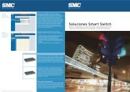
TigerAccess EE<br />
6-Band VDSL2 Switch<br />
◆ 16 VDSL Downlink Ports (1 RJ-21 Connector)<br />
◆ 2 Gigabit Ethernet Combination Ports (RJ-45/SFP)<br />
◆ 1 Fast Ethernet Management Port (RJ-45)<br />
◆ Non-blocking switching architecture<br />
◆ Spanning Tree Protocol, RSTP, and MSTP<br />
◆ Up to 12 LACP or static 8-port trunks<br />
◆ Layer 2/3/4 CoS support through eight priority queues<br />
◆ Layer 3/4 traffic priority with IP Precedence and IP DSCP<br />
◆ Full support for VLANs with GVRP<br />
◆ IGMP multicast filtering and snooping<br />
◆ Manageable via console, Web, SNMP/RMON<br />
◆ Security features: ACL, RADIUS, 802.1x<br />
◆ VDSL line configuration using Long-Reach Ethernet<br />
(LRE) commands, line profiles, and alarm profiles<br />
<strong>Installation</strong> <strong>Guide</strong><br />
<strong>SMC</strong>7816M/VSW
TigerAccess EE<br />
<strong>Installation</strong> <strong>Guide</strong><br />
From <strong>SMC</strong>’s Tiger line of feature-rich workgroup LAN solutions<br />
20 Mason<br />
Irvine, CA 92618<br />
Phone: (949) 679-8000<br />
February 2007<br />
Pub. # 149100012100H
Information furnished by <strong>SMC</strong> Networks, Inc. (<strong>SMC</strong>) is believed to be accurate and reliable. However, no<br />
responsibility is assumed by <strong>SMC</strong> for its use, nor for any infringements of patents or other rights of third<br />
parties which may result from its use. No license is granted by implication or otherwise under any patent or<br />
patent rights of <strong>SMC</strong>. <strong>SMC</strong> reserves the right to change specifications at any time without notice.<br />
Trademarks:<br />
Copyright © 2007 by<br />
<strong>SMC</strong> Networks, Inc.<br />
20 Mason<br />
Irvine, CA 92618<br />
All rights reserved. Printed in Taiwan<br />
<strong>SMC</strong> is a registered trademark; and EZ Switch, TigerAccess, TigerStack and TigerSwitch are trademarks of<br />
<strong>SMC</strong> Networks, Inc. Other product and company names are trademarks or registered trademarks of their<br />
respective holders.
LIMITED WARRANTY<br />
Limited Warranty Statement: <strong>SMC</strong> Networks, Inc. (“<strong>SMC</strong>”) warrants its products to be<br />
free from defects in workmanship and materials, under normal use and service, for the<br />
applicable warranty term. All <strong>SMC</strong> products carry a standard 90-day limited warranty from<br />
the date of purchase from <strong>SMC</strong> or its Authorized Reseller. <strong>SMC</strong> may, at its own discretion,<br />
repair or replace any product not operating as warranted with a similar or functionally<br />
equivalent product, during the applicable warranty term. <strong>SMC</strong> will endeavor to repair or<br />
replace any product returned under warranty within 30 days of receipt of the product.<br />
The standard limited warranty can be upgraded to a Limited Lifetime* warranty by registering<br />
new products within 30 days of purchase from <strong>SMC</strong> or its Authorized Reseller. Registration<br />
can be accomplished via the enclosed product registration card or online via the <strong>SMC</strong> Web<br />
site. Failure to register will not affect the standard limited warranty. The Limited Lifetime<br />
warranty covers a product during the Life of that Product, which is defined as the period of<br />
time during which the product is an “Active” <strong>SMC</strong> product. A product is considered to be<br />
“Active” while it is listed on the current <strong>SMC</strong> price list. As new technologies emerge, older<br />
technologies become obsolete and <strong>SMC</strong> will, at its discretion, replace an older product in its<br />
product line with one that incorporates these newer technologies. At that point, the obsolete<br />
product is discontinued and is no longer an “Active” <strong>SMC</strong> product. A list of discontinued<br />
products with their respective dates of discontinuance can be found at:<br />
http://www.smc.com/index.cfm?action=customer_service_warranty.<br />
All products that are replaced become the property of <strong>SMC</strong>. Replacement products may be<br />
either new or reconditioned. Any replaced or repaired product carries either a 30-day limited<br />
warranty or the remainder of the initial warranty, whichever is longer. <strong>SMC</strong> is not responsible<br />
for any custom software or firmware, configuration information, or memory data of<br />
Customer contained in, stored on, or integrated with any products returned to <strong>SMC</strong> pursuant<br />
to any warranty. Products returned to <strong>SMC</strong> should have any customer-installed accessory or<br />
add-on components, such as expansion modules, removed prior to returning the product for<br />
replacement. <strong>SMC</strong> is not responsible for these items if they are returned with the product.<br />
Customers must contact <strong>SMC</strong> for a Return Material Authorization number prior to returning<br />
any product to <strong>SMC</strong>. Proof of purchase may be required. Any product returned to <strong>SMC</strong><br />
without a valid Return Material Authorization (RMA) number clearly marked on the outside<br />
of the package will be returned to customer at customer’s expense. For warranty claims within<br />
North America, please call our toll-free customer support number at (800) 762-4968.<br />
Customers are responsible for all shipping charges from their facility to <strong>SMC</strong>. <strong>SMC</strong> is<br />
responsible for return shipping charges from <strong>SMC</strong> to customer.<br />
v
vi<br />
WARRANTIES EXCLUSIVE: IF AN <strong>SMC</strong> PRODUCT DOES NOT OPERATE AS<br />
WARRANTED ABOVE, CUSTOMER’S SOLE REMEDY SHALL BE REPAIR OR<br />
REPLACEMENT OF THE PRODUCT IN QUESTION, AT <strong>SMC</strong>’S OPTION. THE<br />
FOREGOING WARRANTIES AND REMEDIES ARE EXCLUSIVE AND ARE IN<br />
LIEU OF ALL OTHER WARRANTIES OR CONDITIONS, EXPRESS OR IMPLIED,<br />
EITHER IN FACT OR BY OPERATION OF LAW, STATUTORY OR OTHERWISE,<br />
INCLUDING WARRANTIES OR CONDITIONS OF MERCHANTABILITY AND<br />
FITNESS FOR A PARTICULAR PURPOSE. <strong>SMC</strong> NEITHER ASSUMES NOR<br />
AUTHORIZES ANY OTHER PERSON TO ASSUME FOR IT ANY OTHER<br />
LIABILITY IN CONNECTION WITH THE SALE, INSTALLATION,<br />
MAINTENANCE OR USE OF ITS PRODUCTS. <strong>SMC</strong> SHALL NOT BE LIABLE<br />
UNDER THIS WARRANTY IF ITS TESTING AND EXAMINATION DISCLOSE THE<br />
ALLEGED DEFECT IN THE PRODUCT DOES NOT EXIST OR WAS CAUSED BY<br />
CUSTOMER’S OR ANY THIRD PERSON’S MISUSE, NEGLECT, IMPROPER<br />
INSTALLATION OR TESTING, UNAUTHORIZED ATTEMPTS TO REPAIR, OR<br />
ANY OTHER CAUSE BEYOND THE RANGE OF THE INTENDED USE, OR BY<br />
ACCIDENT, FIRE, LIGHTNING, OR OTHER HAZARD.<br />
LIMITATION OF LIABILITY: IN NO EVENT, WHETHER BASED IN CONTRACT<br />
OR TORT (INCLUDING NEGLIGENCE), SHALL <strong>SMC</strong> BE LIABLE FOR<br />
INCIDENTAL, CONSEQUENTIAL, INDIRECT, SPECIAL, OR PUNITIVE<br />
DAMAGES OF ANY KIND, OR FOR LOSS OF REVENUE, LOSS OF BUSINESS, OR<br />
OTHER FINANCIAL LOSS ARISING OUT OF OR IN CONNECTION WITH THE<br />
SALE, INSTALLATION, MAINTENANCE, USE, PERFORMANCE, FAILURE, OR<br />
INTERRUPTION OF ITS PRODUCTS, EVEN IF <strong>SMC</strong> OR ITS AUTHORIZED<br />
RESELLER HAS BEEN ADVISED OF THE POSSIBILITY OF SUCH DAMAGES.<br />
SOME STATES DO NOT ALLOW THE EXCLUSION OF IMPLIED WARRANTIES<br />
OR THE LIMITATION OF INCIDENTAL OR CONSEQUENTIAL DAMAGES FOR<br />
CONSUMER PRODUCTS, SO THE ABOVE LIMITATIONS AND EXCLUSIONS<br />
MAY NOT APPLY TO YOU. THIS WARRANTY GIVES YOU SPECIFIC LEGAL<br />
RIGHTS, WHICH MAY VARY FROM STATE TO STATE. NOTHING IN THIS<br />
WARRANTY SHALL BE TAKEN TO AFFECT YOUR STATUTORY RIGHTS.<br />
* <strong>SMC</strong> will provide warranty service for one year following discontinuance from the active<br />
<strong>SMC</strong> price list. Under the limited lifetime warranty, internal and external power supplies, fans,<br />
and cables are covered by a standard one-year warranty from date of purchase.<br />
<strong>SMC</strong> Networks, Inc.<br />
20 Mason<br />
Irvine, CA 92618
FCC - Class A<br />
COMPLIANCES<br />
This equipment has been tested and found to comply with the limits for a Class A digital<br />
device, pursuant to part 15 of the FCC Rules. These limits are designed to provide reasonable<br />
protection against harmful interference when the equipment is operated in a commercial<br />
environment. This equipment generates, uses, and can radiate radio frequency energy and, if<br />
not installed and used in accordance with the instruction manual, may cause harmful<br />
interference to radio communications. Operation of this equipment in a residential area is<br />
likely to cause harmful interference in which case the user will be required to correct the<br />
interference at his own expense.<br />
You are cautioned that changes or modifications not expressly approved by the party<br />
responsible for compliance could void your authority to operate the equipment.<br />
You may use unshielded twisted-pair (UTP) for RJ-45 connections - Category 3 or better for<br />
10 Mbps connections, Category 5 or better for 100 Mbps connections, Category 5, 5e, or 6<br />
for 1000 Mbps connections. For fiber optic connections, you may use 50/125 or 62.5/125<br />
micron multimode fiber or 9/125 micron single-mode fiber.<br />
FCC - Part 68<br />
This equipment complies with Part 68 of FCC Rules. On the base unit of this equipment is a<br />
label that contains, among other information, the FCC Registration Number and Ringer<br />
Equivalence Number (REN) for this equipment. If requested, this information must be given<br />
to the telephone company.<br />
This equipment uses the following USOC jacks: RJ-21.<br />
The REN is useful to determine the quantity of devices you may connect to your telephone<br />
line and still have those entire devices ring when your telephone number is called. In most,<br />
but not all areas, the sum of the REN of all devices connected to one line should not exceed<br />
five (5.0). To be certain of the number of devices you may connect to you line, as determined<br />
by the REN, you should contact your local telephone company to determine the maximum<br />
REN for your calling area.<br />
If your equipment causes harm to the telephone network, the telephone company may<br />
discontinue your service temporarily. If possible, they will notify you in advance. But if<br />
advance notice is not practical, you will be notified as soon as possible. You will be informed<br />
of your right to file a complaint with the FCC. Your telephone company may make changes in<br />
its facilities, equipment, operations or procedures that could affect the proper functioning of<br />
your equipment. If they do, you will be notified in advance to give you an opportunity to<br />
maintain uninterrupted telephone service.<br />
If you experience trouble with this telephone equipment, please contact please contact our<br />
company at the numbers shown on back of this manual for information on obtaining service<br />
or repairs. The telephone company may ask that you disconnect this equipment from the<br />
vii
COMPLIANCES<br />
viii<br />
network until the problem has been corrected or until you are sure that the equipment is not<br />
malfunctioning.<br />
This equipment may not be used on coin service provided by the telephone company.<br />
Connection to party lines is subject to state tariffs.<br />
Industry Canada - Class A<br />
This digital apparatus does not exceed the Class A limits for radio noise emissions from<br />
digital apparatus as set out in the interference-causing equipment standard entitled “Digital<br />
Apparatus,” ICES-003 of the Department of Communications.<br />
Cet appareil numérique respecte les limites de bruits radioélectriques applicables aux appareils<br />
numériques de Classe A prescrites dans la norme sur le matériel brouilleur: “Appareils<br />
Numériques,” NMB-003 édictée par le ministère des Communications.<br />
CE Mark Declaration of Conformance for EMI and<br />
Safety (EEC)<br />
<strong>SMC</strong> contact for these products in Europe is:<br />
<strong>SMC</strong> Networks Europe,<br />
Edificio Conata II,<br />
Calle Fructuós Gelabert 6-8, 2o , 4a ,<br />
08970 - Sant Joan Despí, Barcelona, Spain.<br />
This information technology equipment complies with the requirements of the Council<br />
Directive 89/336/EEC on the Approximation of the laws of the Member States relating to<br />
Electromagnetic Compatibility and 73/23/EEC for electrical equipment used within certain<br />
voltage limits and the Amendment Directive 93/68/EEC. For the evaluation of the<br />
compliance with these Directives, the following standards were applied:<br />
RFI Emission: • Limit class A according to EN 55022:1998<br />
• Limit class A for harmonic current emission according to<br />
EN 61000-3-2/1995<br />
• Limitation of voltage fluctuation and flicker in low-voltage supply<br />
system according to EN 61000-3-3/1995<br />
Immunity: • Product family standard according to EN 55024:1998<br />
• Electrostatic Discharge according to EN 61000-4-2:1995<br />
(Contact Discharge: ±4 kV, Air Discharge: ±8 kV)<br />
• Radio-frequency electromagnetic field according to EN 61000-4-3:1996<br />
(80 - 1000 MHz with 1 kHz AM 80% Modulation: 3 V/m)<br />
• Electrical fast transient/burst according to EN 61000-4-4:1995 (AC/<br />
DC power supply: ±1 kV, Data/Signal lines: ±0.5 kV)
COMPLIANCES<br />
• Surge immunity test according to EN 61000-4-5:1995<br />
(AC/DC Line to Line: ±1 kV, AC/DC Line to Earth: ±2 kV)<br />
• Immunity to conducted disturbances, Induced by radio-frequency<br />
fields: EN 61000-4-6:1996 (0.15 - 80 MHz with<br />
1 kHz AM 80% Modulation: 3 V/m)<br />
• Power frequency magnetic field immunity test according to<br />
EN 61000-4-8:1993 (1 A/m at frequency 50 Hz)<br />
• Voltage dips, short interruptions and voltage variations immunity test<br />
according to EN 61000-4-11:1994 (>95% Reduction @10 ms, 30%<br />
Reduction @500 ms, >95% Reduction @5000 ms)<br />
LVD: • EN 60950-1:2001<br />
Warning: Do not plug a phone jack connector in the RJ-45 port. This may damage this device.<br />
Attention: Les raccordeurs ne sont pas utilisés pour le système téléphonique!<br />
Safety Compliance<br />
Warning: Fiber Optic Port Safety<br />
CLASS I<br />
LASER DEVICE<br />
Avertissment: Ports pour fibres optiques - sécurité sur le plan optique<br />
DISPOSITIF LASER<br />
DE CLASSE I<br />
Warnhinweis: Faseroptikanschlüsse - Optische Sicherheit<br />
LASERGERÄT<br />
DER KLASSE I<br />
PSE Alarm<br />
When using a fiber optic port, never look at the transmit laser while<br />
it is powered on. Also, never look directly at the fiber TX port and<br />
fiber cable ends when they are powered on.<br />
Ne regardez jamais le laser tant qu’il est sous tension. Ne regardez<br />
jamais directement le port TX (Transmission) à fibres optiques et les<br />
embouts de câbles à fibres optiques tant qu’ils sont sous tension.<br />
Niemals ein Übertragungslaser betrachten, während dieses<br />
eingeschaltet ist. Niemals direkt auf den Faser-TX-Anschluß und auf<br />
die Faserkabelenden schauen, während diese eingeschaltet sind.<br />
本製品に同梱いたしております電源コードセットは、<br />
本製品専用です。本電源コードセットは、本製品以外の<br />
製品並びに他の用途でご使用いただくことは出来ません。<br />
製品本体に同梱された電源コードセットを利用し、他製品<br />
の電源コードセットを使用しないで下さい。<br />
ix
COMPLIANCES<br />
x<br />
Power Cord Safety<br />
Please read the following safety information carefully before installing the switch:<br />
Warning: <strong>Installation</strong> and removal of the unit must be carried out by qualified personnel only.<br />
• The unit must be connected to an earthed (grounded) outlet to comply with international<br />
safety standards.<br />
• Do not connect the unit to an A.C. outlet (power supply) without an earth (ground)<br />
connection.<br />
• The appliance coupler (the connector to the unit and not the wall plug) must have a<br />
configuration for mating with an EN 60320/IEC 320 appliance inlet.<br />
• The socket outlet must be near to the unit and easily accessible. You can only remove power<br />
from the unit by disconnecting the power cord from the outlet.<br />
• This unit operates under SELV (Safety Extra Low Voltage) conditions according to<br />
IEC 60950. The conditions are only maintained if the equipment to which it is connected<br />
also operates under SELV conditions.<br />
France and Peru only<br />
This unit cannot be powered from IT † supplies. If your supplies are of IT type, this unit must<br />
be powered by 230 V (2P+T) via an isolation transformer ratio 1:1, with the secondary<br />
connection point labelled Neutral, connected directly to earth (ground).<br />
† Impédance à la terre<br />
Important! Before making connections, make sure you have the correct cord set. Check it<br />
(read the label on the cable) against the following:<br />
Power Cord Set<br />
U.S.A. and Canada The cord set must be UL-approved and CSA certified.<br />
The minimum specifications for the flexible cord are:<br />
- No. 18 AWG - not longer than 2 meters, or 16 AWG.<br />
- Type SV or SJ<br />
- 3-conductor<br />
The cord set must have a rated current capacity of at least 10 A<br />
The attachment plug must be an earth-grounding type with NEMA<br />
5-15P (15 A, 125 V) or NEMA 6-15P (15 A, 250 V) configuration.<br />
Denmark The supply plug must comply with Section 107-2-D1, Standard<br />
DK2-1a or DK2-5a.<br />
Switzerland The supply plug must comply with SEV/ASE 1011.<br />
U.K. The supply plug must comply with BS1363 (3-pin 13 A) and be<br />
fitted with a 5 A fuse which complies with BS1362.<br />
The mains cord must be or marked and be of<br />
type HO3VVF3GO.75 (minimum).
Power Cord Set (Continued)<br />
Veuillez lire à fond l'information de la sécurité suivante avant<br />
d'installer le Switch:<br />
COMPLIANCES<br />
Europe The supply plug must comply with CEE7/7 (“SCHUKO”).<br />
The mains cord must be or marked and be of<br />
type HO3VVF3GO.75 (minimum).<br />
IEC-320 receptacle.<br />
AVERTISSEMENT: L’installation et la dépose de ce groupe doivent être confiés à un<br />
personnel qualifié.<br />
• Ne branchez pas votre appareil sur une prise secteur (alimentation électrique) lorsqu'il n'y a<br />
pas de connexion de mise à la terre (mise à la masse).<br />
• Vous devez raccorder ce groupe à une sortie mise à la terre (mise à la masse) afin de<br />
respecter les normes internationales de sécurité.<br />
• Le coupleur d’appareil (le connecteur du groupe et non pas la prise murale) doit respecter<br />
une configuration qui permet un branchement sur une entrée d’appareil EN 60320/IEC<br />
320.<br />
• La prise secteur doit se trouver à proximité de l’appareil et son accès doit être facile. Vous<br />
ne pouvez mettre l’appareil hors circuit qu’en débranchant son cordon électrique au niveau<br />
de cette prise.<br />
• L’appareil fonctionne à une tension extrêmement basse de sécurité qui est conforme à la<br />
norme IEC 60950. Ces conditions ne sont maintenues que si l’équipement auquel il est<br />
raccordé fonctionne dans les mêmes conditions.<br />
xi
COMPLIANCES<br />
xii<br />
France et Pérou uniquement:<br />
Ce groupe ne peut pas être alimenté par un dispositif à impédance à la terre. Si vos<br />
alimentations sont du type impédance à la terre, ce groupe doit être alimenté par une tension<br />
de 230 V (2 P+T) par le biais d’un transformateur d’isolement à rapport 1:1, avec un point<br />
secondaire de connexion portant l’appellation Neutre et avec raccordement direct à la terre<br />
(masse).<br />
Cordon électrique - Il doit être agréé dans le pays d’utilisation<br />
Etats-Unis et<br />
Canada:<br />
Le cordon doit avoir reçu l’homologation des UL et un certificat de<br />
la CSA.<br />
Les spécifications minimales pour un cable flexible sont AWG No.<br />
18, ouAWG No. 16 pour un cable de longueur inférieure à 2 métres.<br />
- type SV ou SJ<br />
- 3 conducteurs<br />
Le cordon doit être en mesure d’acheminer un courant nominal<br />
d’au moins 10 A.<br />
La prise femelle de branchement doit être du type à mise à la terre<br />
(mise à la masse) et respecter la configuration NEMA 5-15P (15 A,<br />
125 V) ou NEMA 6-15P (15 A, 250 V).<br />
Danemark: La prise mâle d’alimentation doit respecter la section 107-2 D1 de<br />
la norme DK2 1a ou DK2 5a.<br />
Suisse: La prise mâle d’alimentation doit respecter la norme SEV/ASE<br />
1011.<br />
Europe La prise secteur doit être conforme aux normes CEE 7/7<br />
(“SCHUKO”)<br />
LE cordon secteur doit porter la mention ou <br />
et doit être de type HO3VVF3GO.75 (minimum).<br />
Bitte unbedingt vor dem Einbauen des Switches die folgenden<br />
Sicherheitsanweisungen durchlesen:<br />
WARNUNG: Die <strong>Installation</strong> und der Ausbau des Geräts darf nur durch Fachpersonal<br />
erfolgen.<br />
• Das Gerät sollte nicht an eine ungeerdete Wechselstromsteckdose angeschlossen werden.<br />
• Das Gerät muß an eine geerdete Steckdose angeschlossen werden, welche die<br />
internationalen Sicherheitsnormen erfüllt.<br />
• Der Gerätestecker (der Anschluß an das Gerät, nicht der Wandsteckdosenstecker) muß<br />
einen gemäß EN 60320/IEC 320 konfigurierten Geräteeingang haben.<br />
• Die Netzsteckdose muß in der Nähe des Geräts und leicht zugänglich sein. Die<br />
Stromversorgung des Geräts kann nur durch Herausziehen des Gerätenetzkabels aus der<br />
Netzsteckdose unterbrochen werden.<br />
• Der Betrieb dieses Geräts erfolgt unter den SELV-Bedingungen<br />
(Sicherheitskleinstspannung) gemäß IEC 60950. Diese Bedingungen sind nur gegeben,
COMPLIANCES<br />
wenn auch die an das Gerät angeschlossenen Geräte unter SELV-Bedingungen betrieben<br />
werden.<br />
Stromkabel. Dies muss von dem Land, in dem es benutzt wird geprüft werden:<br />
Schweiz Dieser Stromstecker muß die SEV/ASE 1011Bestimmungen<br />
einhalten.<br />
Europe Das Netzkabel muß vom Typ HO3VVF3GO.75<br />
(Mindestanforderung) sein und die Aufschrift oder<br />
tragen.<br />
Der Netzstecker muß die Norm CEE 7/7 erfüllen (”SCHUKO”).<br />
Warnings and Cautionary Messages<br />
Warning: This product does not contain any serviceable user parts.<br />
Warning: <strong>Installation</strong> and removal of the unit must be carried out by qualified personnel<br />
only.<br />
Warning: When connecting this device to a power outlet, connect the field ground lead<br />
on the tri-pole power plug to a valid earth ground line to prevent electrical<br />
hazards.<br />
Warning: This switch uses lasers to transmit signals over fiber optic cable. The lasers are<br />
compliant with the requirements of a Class 1 Laser Product and are inherently<br />
eye safe in normal operation. However, you should never look directly at a<br />
transmit port when it is powered on.<br />
Caution: Wear an anti-static wrist strap or take other suitable measures to prevent<br />
electrostatic discharge when handling this equipment.<br />
Caution: Do not plug a phone jack connector in the RJ-45 port. This may damage this<br />
device. Les raccordeurs ne sont pas utilisé pour le système téléphonique!<br />
Caution: Use only twisted-pair cables with RJ-45 connectors that conform to FCC<br />
standards.<br />
Warnings (in German)<br />
Achtung: Dieses Produkt enthält keine Teile, die eine Wartung vom Benutzer benötigen.<br />
Achtung: <strong>Installation</strong> und Deinstallation des Gerätes müssen von qualifiziertem<br />
Servicepersonal durchgeführt werden.<br />
Achtung: Wenn das Gerät an eine Steckdose angeschlossen wird, muß der Masseanschluß<br />
am dreipoligen Netzstecker mit Schutzerde verbunden werden, um elektrische<br />
Gefahren zu vermeiden.<br />
Achtung: Dieses Gerät nutzt Laser zur Signalübertragung über Glasfasern. Die Laser<br />
entsprechen den Anforderungen an eine Lasereinrichtung der Klasse 1 und sind<br />
durch ihre Bauart im normalen Betrieb sicher für die Augen. Trotzdem sollte<br />
niemals direkt in den einen Übertragungskanal geblickt werden, wenn er<br />
eingeschaltet ist.<br />
xiii
COMPLIANCES<br />
xiv<br />
Environmental Statement<br />
The manufacturer of this product endeavours to sustain an environmentally-friendly policy<br />
throughout the entire production process. This is achieved though the following means:<br />
• Adherence to national legislation and regulations on environmental production standards.<br />
• Conservation of operational resources.<br />
• Waste reduction and safe disposal of all harmful un-recyclable by-products.<br />
• Recycling of all reusable waste content.<br />
• Design of products to maximize recyclables at the end of the product’s life span.<br />
• Continual monitoring of safety standards.<br />
End of Product Life Span<br />
This product is manufactured in such a way as to allow for the recovery and disposal of all<br />
included electrical components once the product has reached the end of its life.<br />
Manufacturing Materials<br />
There are no hazardous nor ozone-depleting materials in this product.<br />
Documentation<br />
All printed documentation for this product uses biodegradable paper that originates from<br />
sustained and managed forests. The inks used in the printing process are non-toxic.<br />
Purpose<br />
This guide details the hardware features of the switches, including Its physical and<br />
performance-related characteristics, and how to install each switch.<br />
Audience<br />
This guide is for system administrators with a working knowledge of network management.<br />
You should be familiar with switching and networking concepts.<br />
Zielgruppe Dieser Anleitung ist fuer Systemadministratoren mit Erfahrung im<br />
Netzwerkmangement. Sie sollten mit Switch- und Netzwerkkonzepten vertraut sein.<br />
Related Publications<br />
The following publication gives specific information on how to operate and use the<br />
management functions of the switches:<br />
The <strong>SMC</strong>7816M/VSW Management <strong>Guide</strong><br />
Also, as part of both switches firmware, there is an online web-based help that describes all<br />
management related features.
TABLE OF CONTENTS<br />
1 About the TigerAccess EE Switch . . . . . . . . . . . . . . . 1-1<br />
Overview . . . . . . . . . . . . . . . . . . . . . . . . . . . . . . . . . . . . . . . . . . . . . . . . . 1-1<br />
VDSL Technology . . . . . . . . . . . . . . . . . . . . . . . . . . . . . . . . . . . . 1-3<br />
Switch Architecture . . . . . . . . . . . . . . . . . . . . . . . . . . . . . . . . . . . 1-4<br />
Network Management Options . . . . . . . . . . . . . . . . . . . . . . . . . . 1-4<br />
Description of Hardware . . . . . . . . . . . . . . . . . . . . . . . . . . . . . . . . . . . . . 1-5<br />
RJ-21 Ports . . . . . . . . . . . . . . . . . . . . . . . . . . . . . . . . . . . . . . . . . . 1-6<br />
1000BASE-T Ports . . . . . . . . . . . . . . . . . . . . . . . . . . . . . . . . . . . . 1-6<br />
SFP Slots . . . . . . . . . . . . . . . . . . . . . . . . . . . . . . . . . . . . . . . . . . . . 1-7<br />
Management Port . . . . . . . . . . . . . . . . . . . . . . . . . . . . . . . . . . . . . 1-7<br />
Console Port . . . . . . . . . . . . . . . . . . . . . . . . . . . . . . . . . . . . . . . . . 1-8<br />
Ethernet-over-VDSL CPE (Optional Equipment) . . . . . . . . . . . 1-8<br />
Port and System Status LEDs . . . . . . . . . . . . . . . . . . . . . . . . . . . 1-8<br />
Power Supply Socket . . . . . . . . . . . . . . . . . . . . . . . . . . . . . . . . . 1-10<br />
Key Features . . . . . . . . . . . . . . . . . . . . . . . . . . . . . . . . . . . . . . . . . . . . . . 1-10<br />
2 Network Planning . . . . . . . . . . . . . . . . . . . . . . . . . . . . 2-1<br />
Introduction to Switching . . . . . . . . . . . . . . . . . . . . . . . . . . . . . . . . . . . . 2-1<br />
Application Examples . . . . . . . . . . . . . . . . . . . . . . . . . . . . . . . . . . . . . . . 2-1<br />
Internet Connections . . . . . . . . . . . . . . . . . . . . . . . . . . . . . . . . . . 2-2<br />
Remote Connections with Fiber Cable . . . . . . . . . . . . . . . . . . . . 2-3<br />
Making VLAN Connections . . . . . . . . . . . . . . . . . . . . . . . . . . . . 2-3<br />
Application Notes . . . . . . . . . . . . . . . . . . . . . . . . . . . . . . . . . . . . . . . . . . 2-5<br />
3 Installing the Switch . . . . . . . . . . . . . . . . . . . . . . . . . . . 3-1<br />
Preparing the Site for VDSL/POTS Connections . . . . . . . . . . . . . . . . . 3-1<br />
Installing Additional Equipment . . . . . . . . . . . . . . . . . . . . . . . . . 3-2<br />
Verifying Site Requirement . . . . . . . . . . . . . . . . . . . . . . . . . . . . . . . . . . . 3-2<br />
Installing Ethernet Cabling . . . . . . . . . . . . . . . . . . . . . . . . . . . . . . . . . . . 3-3<br />
Equipment Checklist . . . . . . . . . . . . . . . . . . . . . . . . . . . . . . . . . . . . . . . . 3-4<br />
Package Contents . . . . . . . . . . . . . . . . . . . . . . . . . . . . . . . . . . . . . 3-4<br />
Optional Rack-Mounting Equipment . . . . . . . . . . . . . . . . . . . . . 3-5<br />
Mounting . . . . . . . . . . . . . . . . . . . . . . . . . . . . . . . . . . . . . . . . . . . . . . . . . 3-5<br />
Rack Mounting . . . . . . . . . . . . . . . . . . . . . . . . . . . . . . . . . . . . . . . 3-5<br />
Desktop or Shelf Mounting . . . . . . . . . . . . . . . . . . . . . . . . . . . . . 3-7<br />
xv
TABLE OF CONTENTS<br />
xvi<br />
Installing an Optional SFP Transceiver . . . . . . . . . . . . . . . . . . . . . . . . . 3-8<br />
Connecting to a Power Source . . . . . . . . . . . . . . . . . . . . . . . . . . . . . . . . 3-9<br />
Connecting to the Console Port . . . . . . . . . . . . . . . . . . . . . . . . . . . . . . 3-10<br />
Wiring Map for Serial Cable . . . . . . . . . . . . . . . . . . . . . . . . . . . . 3-10<br />
4 Making Network Connections . . . . . . . . . . . . . . . . . . . 4-1<br />
Connecting RJ-21 Cables . . . . . . . . . . . . . . . . . . . . . . . . . . . . . . . . . . . . . 4-1<br />
Connecting to the Punch-down Blocks . . . . . . . . . . . . . . . . . . . . 4-2<br />
Using Patch Panels . . . . . . . . . . . . . . . . . . . . . . . . . . . . . . . . . . . . 4-3<br />
Connecting Twisted-Pair Devices . . . . . . . . . . . . . . . . . . . . . . . . . . . . . . 4-4<br />
Cabling <strong>Guide</strong>lines . . . . . . . . . . . . . . . . . . . . . . . . . . . . . . . . . . . . 4-4<br />
Network Wiring Connections . . . . . . . . . . . . . . . . . . . . . . . . . . . 4-4<br />
Connecting to PCs, Servers, Hubs and Switches . . . . . . . . . . . . 4-5<br />
Connecting Fiber Optic Devices . . . . . . . . . . . . . . . . . . . . . . . . . . . . . . . 4-6<br />
Connectivity Rules . . . . . . . . . . . . . . . . . . . . . . . . . . . . . . . . . . . . . . . . . . 4-7<br />
1000BASE-T Cable Requirements . . . . . . . . . . . . . . . . . . . . . . . 4-8<br />
1000 Mbps Gigabit Ethernet Cable Lengths . . . . . . . . . . . . . . . . 4-8<br />
100 Mbps Fast Ethernet Cable Lengths . . . . . . . . . . . . . . . . . . . 4-9<br />
10 Mbps Ethernet Cable Lengths . . . . . . . . . . . . . . . . . . . . . . . . 4-9<br />
Cable Labeling and Connection Records . . . . . . . . . . . . . . . . . . . . . . . 4-10
APPENDICES:<br />
TABLE OF CONTENTS<br />
A Troubleshooting . . . . . . . . . . . . . . . . . . . . . . . . . . . . . .A-1<br />
Diagnosing Switch Indicators . . . . . . . . . . . . . . . . . . . . . . . . . . . . . . . . . A-1<br />
Power and Cooling Problems . . . . . . . . . . . . . . . . . . . . . . . . . . . . . . . . . A-3<br />
<strong>Installation</strong> . . . . . . . . . . . . . . . . . . . . . . . . . . . . . . . . . . . . . . . . . . . . . . . . A-3<br />
In-Band Access . . . . . . . . . . . . . . . . . . . . . . . . . . . . . . . . . . . . . . . . . . . . A-3<br />
B Cables . . . . . . . . . . . . . . . . . . . . . . . . . . . . . . . . . . . . . .B-1<br />
Twisted-Pair Cable and Pin Assignments . . . . . . . . . . . . . . . . . . . . . . . . B-1<br />
10BASE-T/100BASE-TX Pin Assignments . . . . . . . . . . . . . . . . B-2<br />
Straight-Through Wiring . . . . . . . . . . . . . . . . . . . . . . . . . . . . . . . B-3<br />
Crossover Wiring . . . . . . . . . . . . . . . . . . . . . . . . . . . . . . . . . . . . . B-4<br />
1000BASE-T Pin Assignments . . . . . . . . . . . . . . . . . . . . . . . . . . B-5<br />
1000BASE-T Cable Requirements . . . . . . . . . . . . . . . . . . . . . . . B-6<br />
Cable Testing for Existing Category 5 Cable . . . . . . . . . . . . . . . B-6<br />
Adjusting Existing Category 5 Cabling to Run 1000BASE-T . . B-6<br />
Fiber Standards . . . . . . . . . . . . . . . . . . . . . . . . . . . . . . . . . . . . . . . . . . . . . B-7<br />
RJ-21 Port Pin Assignments . . . . . . . . . . . . . . . . . . . . . . . . . . . . . . . . . . B-8<br />
Console Port Pin Assignments . . . . . . . . . . . . . . . . . . . . . . . . . . . . . . . . B-9<br />
DB-9 Port Pin Assignments . . . . . . . . . . . . . . . . . . . . . . . . . . . . . B-9<br />
Console Port to 9-Pin DTE Port on PC . . . . . . . . . . . . . . . . . . B-10<br />
Console to 25-Pin DTE Port on PC . . . . . . . . . . . . . . . . . . . . B-10<br />
C Specifications . . . . . . . . . . . . . . . . . . . . . . . . . . . . . . . .C-1<br />
Physical Characteristics . . . . . . . . . . . . . . . . . . . . . . . . . . . . . . . . . . . . . . C-1<br />
Switch Features . . . . . . . . . . . . . . . . . . . . . . . . . . . . . . . . . . . . . . . . . . . . C-3<br />
Management Features . . . . . . . . . . . . . . . . . . . . . . . . . . . . . . . . . . . . . . . C-3<br />
Standards . . . . . . . . . . . . . . . . . . . . . . . . . . . . . . . . . . . . . . . . . . . . . . . . . C-4<br />
Compliances . . . . . . . . . . . . . . . . . . . . . . . . . . . . . . . . . . . . . . . . . . . . . . . C-4<br />
D Ordering Information . . . . . . . . . . . . . . . . . . . . . . . . . D-1<br />
Glossary<br />
Index<br />
xvii
xviii<br />
TABLES<br />
Table 1-1 Optional SFP Transceivers . . . . . . . . . . . . . . . . . . . . . . . . . . . . 1-7<br />
Table 1-2 Port Status LEDs . . . . . . . . . . . . . . . . . . . . . . . . . . . . . . . . . . . 1-9<br />
Table 1-3 System Status LEDs . . . . . . . . . . . . . . . . . . . . . . . . . . . . . . . . . 1-9<br />
Table 3-1 Optional SFP Transceivers . . . . . . . . . . . . . . . . . . . . . . . . . . . . 3-8<br />
Table 3-2 Wiring Map for Serial Cable . . . . . . . . . . . . . . . . . . . . . . . . . . 3-10<br />
Table 4-1 Maximum 1000BASE-T Gigabit Ethernet Cable Length . . . . 4-8<br />
Table 4-2 Maximum 1000BASE-SX Gigabit Ethernet Cable Length . . 4-8<br />
Table 4-4 Maximum 1000BASE-ZX Gigabit Ethernet Cable Length . . 4-9<br />
Table 4-5 Maximum Fast Ethernet Cable Length . . . . . . . . . . . . . . . . . . 4-9<br />
Table 4-6 Maximum Ethernet Cable Length . . . . . . . . . . . . . . . . . . . . . . 4-9<br />
Table 4-3 Maximum 1000BASE-LX Gigabit Ethernet Cable Length . . 4-9<br />
Table A-1 Diagnosing Switch Indicators . . . . . . . . . . . . . . . . . . . . . . . . .A-1<br />
Table B-1 10/100BASE-TX MDI and MDI-X Port Pinouts . . . . . . . . . B-2<br />
Table B-2 1000BASE-T MDI and MDI-X Port Pinouts . . . . . . . . . . . . . B-5<br />
Table B-3 RJ-21 Port Pin Assignments (PBX/MDF connector) . . . . . . B-8<br />
Table B-4 RJ-21 Port Pin Assignments (VDSL Line connector) . . . . . . B-8<br />
Table B-5 DB-9 Port Pin Assignments . . . . . . . . . . . . . . . . . . . . . . . . . . . B-9<br />
Table B-6 Console Port to 9-Pin DTE Port on PC . . . . . . . . . . . . . . . . B-10<br />
Table B-7 Console to 25-Pin DTE Port on PC . . . . . . . . . . . . . . . . . . . B-10<br />
Table D-1 TigerAccess EE Products and Accessories . . . . . . . . . . . . . . .D-1
FIGURES<br />
Figure 1-1 VDSL Application . . . . . . . . . . . . . . . . . . . . . . . . . . . . . . 1-3<br />
Figure 1-2 Front and Rear Panels . . . . . . . . . . . . . . . . . . . . . . . . . . . . 1-6<br />
Figure 1-3 Port and System LEDs . . . . . . . . . . . . . . . . . . . . . . . . . . . 1-8<br />
Figure 1-4 Power Supply Socket . . . . . . . . . . . . . . . . . . . . . . . . . . . 1-10<br />
Figure 2-1 Internet Connections . . . . . . . . . . . . . . . . . . . . . . . . . . . . 2-2<br />
Figure 2-2 Remote Connections with Fiber Cable . . . . . . . . . . . . . . 2-3<br />
Figure 2-3 Making VLAN Connections . . . . . . . . . . . . . . . . . . . . . . . 2-4<br />
Figure 3-1 Wiring before VDSL Switch <strong>Installation</strong> . . . . . . . . . . . . . 3-1<br />
Figure 3-2 Wiring after Switch <strong>Installation</strong> . . . . . . . . . . . . . . . . . . . . 3-2<br />
Figure 3-3 RJ-45 Connections . . . . . . . . . . . . . . . . . . . . . . . . . . . . . . 3-4<br />
Figure 3-4 Attaching the Brackets . . . . . . . . . . . . . . . . . . . . . . . . . . . 3-6<br />
Figure 3-5 Installing the Switch in a Rack . . . . . . . . . . . . . . . . . . . . . 3-6<br />
Figure 3-6 Attaching the Adhesive Feet . . . . . . . . . . . . . . . . . . . . . . 3-7<br />
Figure 3-7 Inserting an SFP Transceiver into a Slot . . . . . . . . . . . . . 3-8<br />
Figure 3-8 Power Socket . . . . . . . . . . . . . . . . . . . . . . . . . . . . . . . . . . . 3-9<br />
Figure 3-9 Serial Port (RJ-45) Pin-Out . . . . . . . . . . . . . . . . . . . . . . . 3-10<br />
Figure 4-1 Connecting to the Punch-down Blocks . . . . . . . . . . . . . . 4-2<br />
Figure 4-2 Using Patch Panels . . . . . . . . . . . . . . . . . . . . . . . . . . . . . . 4-3<br />
Figure 4-3 Network Wiring Connections . . . . . . . . . . . . . . . . . . . . . 4-4<br />
Figure 4-4 Customer Premises Connections . . . . . . . . . . . . . . . . . . . 4-5<br />
Figure 4-5 Making LC Port Connections . . . . . . . . . . . . . . . . . . . . . . 4-7<br />
Figure B-1 RJ-45 Connector Pin Numbers . . . . . . . . . . . . . . . . . . . . B-1<br />
Figure B-2 Straight-through Wiring . . . . . . . . . . . . . . . . . . . . . . . . . . B-3<br />
Figure B-3 Crossover Wiring . . . . . . . . . . . . . . . . . . . . . . . . . . . . . . . B-4<br />
Figure B-4 RJ-21 Port Pins . . . . . . . . . . . . . . . . . . . . . . . . . . . . . . . . . B-8<br />
Figure B-5 DB-9 Console Port Pin Numbers . . . . . . . . . . . . . . . . . . B-9<br />
xix
FIGURES<br />
xx
Overview<br />
CHAPTER 1<br />
ABOUT THE<br />
TIGERACCESS EE SWITCH<br />
This Ethernet-over-VDSL system consists of end-user CPEs (Customer<br />
Premise Equipment) connected to a VDSL switch by standard telephone<br />
cable. The VDSL connection delivers an Ethernet data link while<br />
simultaneously supporting standard telephone services. The system can be<br />
deployed in any multi-dwelling/multi-tenant environment (apartment<br />
blocks, hotels, or office complex) to provide both high-speed Internet<br />
access and telephone services without any need for re-wiring.<br />
The VDSL switch has a built-in POTS splitter that combines both the data<br />
and phone signals coming from your Internet and telephone service<br />
providers, and passes these signals directly over standard telephone wiring<br />
to multiple users in the same building. A CPE is then used to separate<br />
these signals and pass them on to a customer’s computer and telephone<br />
equipment. Using the pre-defined profiles, in-building connections can<br />
operate up to 100 Mbps upstream and downstream for runs up to 200<br />
meters (656 ft).<br />
Note: Type-1 26 AWG (100 ohm)/0.4 mm, or Type-2 24 AWG (100<br />
ohm)/0.5 mm cable may be installed to achieve the maximum<br />
distance. However, typically 24 AWG (100 ohm)/0.5 mm wire<br />
provides better performance than 26 AWG (100 ohm)/0.4 mm wire.<br />
Note the distance may be limited by factors such as how the cable is<br />
bundled, and the interference and noise on the link.<br />
1-1
ABOUT THE TIGERACCESS EE SWITCH<br />
1-2<br />
The VDSL switch is typically located in a wiring closet or other central<br />
location of a multi-dwelling/multi-tenant unit, campus or enterprise. An<br />
Internet connection is provided from the ISP to the customer’s building<br />
over fiber optic cable, running Ethernet directly over a 1 Gbps connection.<br />
(Trunking both uplink ports together can provide a 2 Gbps connection.)<br />
This kind of WAN connection is referred to as fiber To The Building<br />
(FTTB). The data and phone signals for each user are combined in the<br />
switch, and passed over VDSL lines to individual customers.<br />
The CPE at the other end of the VDSL line connects to any PC or<br />
Macintosh equipped with a 10/100BASE-TX network interface card. Your<br />
existing telephone, modem, or fax machine simply plugs into the CPE’s<br />
phone port. There is no need for special terminators or filters. In fact,<br />
there is no need to modify your wiring at all. Since the VDSL connection is<br />
based on Ethernet, no further complex software configurations are<br />
required.
VDSL Technology<br />
Existing Phone<br />
Lines to Clients<br />
Punch Down<br />
Blocks /<br />
Patch Panels<br />
OVERVIEW<br />
VDSL2 (Very High Bit-Rate Digital Subscriber Line) is at the high-end of<br />
all the DSL technologies, offering the best combination of fiber optic and<br />
copper to provide high-speed broadband Internet access. VDSL’s primary<br />
application is in providing a broadband data service to multi-tenant<br />
residential or commercial buildings. In this implementation, fiber optic<br />
cable carries data from an Internet Service Provider to the building; then<br />
the installed telephone copper wires take the data and deliver it to<br />
individual units within that building.<br />
Floor 2<br />
Floor 1<br />
VDSL Lines<br />
VDSL CPE<br />
VDSL CPE<br />
Telephone<br />
Telephone/Fax<br />
VDSL Switch<br />
100-240V 50-60Hz 1A<br />
Console<br />
TM<br />
TigerAccess EE Switch<br />
<strong>SMC</strong>7816M/ VSW<br />
1 5 9 13<br />
E<br />
Power<br />
Line<br />
POTS<br />
Mgmt O 17 E<br />
O 18<br />
E<br />
2 6 10 14 17<br />
O<br />
Fault<br />
3 7 11 15<br />
E<br />
Diag<br />
4 8 12 16 18<br />
O<br />
Mgmt<br />
ESD PORT<br />
Phone Lines<br />
Rooms/Clients<br />
Rooms/Clients<br />
PBX<br />
Multi-dwelling/Multi-tenant Building<br />
Local Servers<br />
(Locally Hosted Services,<br />
Video Servers, Billing)<br />
MPOE<br />
Fiber Optic Link to ISP<br />
Figure 1-1 VDSL Application<br />
Telephone Line<br />
from Central Office<br />
Central Office<br />
(PSTN)<br />
ISP<br />
(Internet)<br />
VDSL provides high-speed Internet access over existing phone lines by<br />
making use of previously unused frequency bandwidth above the voice<br />
band (i.e., up to 30 MHz with VDSL2). By placing VDSL signals above the<br />
frequency of the voice signal, a VDSL service can coexist on the same line<br />
as other telephone services. VDSL can operate symmetrically, providing the<br />
same data rate in both directions, or asymmetrically, providing a higher data<br />
rate in the downstream (receive) direction than in the upstream (transmit)<br />
direction.<br />
1-3
ABOUT THE TIGERACCESS EE SWITCH<br />
1-4<br />
VDSL can deliver high-performance online applications, such as<br />
high-quality video and other switched multimedia services. This<br />
Ethernet-over-VDSL system provides robust performance, with a<br />
maximum symmetric data rate of 100 Mbps for runs up to 200 meters<br />
(656 ft). This system is based on advanced VDSL2 Multi-Carrier<br />
Modulation (MCM) technology with adaptive channel equalization that<br />
overcomes bridge taps and other line distortions. Reed-Solomon Forward<br />
Error Correction and interleaving protect against errors due to impulse<br />
noise and enable recovery from signal interruptions. Frequency Division<br />
Duplexing (FDD) separates downstream and upstream channels and<br />
allows VDSL signals to coexist with regular telephone services. A power<br />
back-off mechanism is also implemented to reduce noise from crosstalk in<br />
line bundles.<br />
Switch Architecture<br />
The VDSL Switch employs a wire-speed, non-blocking switching fabric.<br />
This permits simultaneous wire-speed transport of multiple packets at low<br />
latency on all ports. This switch also features full-duplex capability on all<br />
ports, which effectively doubles the bandwidth of each connection.<br />
For communications between different VLANs, this switch uses IP<br />
routing. For communications within the same VLAN, the switch uses<br />
store-and-forward switching to ensure maximum data integrity. With<br />
store-and-forward switching, the entire packet must be received into a<br />
buffer and checked for validity before being forwarded. This prevents<br />
errors from being propagated throughout the network.<br />
Network Management Options<br />
This switch contains a comprehensive array of LEDs for “at-a-glance”<br />
monitoring of network and port status. It also includes a management<br />
agent that allows you to configure or monitor the switch using its<br />
embedded management software, or via SNMP applications. To manage<br />
the switch, you can make a direct connection to the console port<br />
(out-of-band), or you can manage the switch through a network
DESCRIPTION OF HARDWARE<br />
connection (in-band) using Telnet, the on-board web agent, or<br />
SNMP-based network management software.<br />
The management port provides a dedicated management channel that<br />
operates outside of the data transport network. This makes it possible to<br />
re-configure or troubleshoot the switch over either a local or remote<br />
connection when access via the data channel is not possible or deemed<br />
insecure.<br />
For a detailed description of the switch’s advanced features, refer to the<br />
Management <strong>Guide</strong>.<br />
Description of Hardware<br />
This device is an intelligent Layer 2 VDSL2 switch with 16 VDSL ports for<br />
subscriber access to the data network, and two Gigabit Ethernet<br />
combination ports * for uplink traffic. The uplink ports are implemented as<br />
10/100/1000BASE-T ports shared with SFP transceiver slots (see Figure<br />
1-1, Ports 17-18). The switch also includes one 10/100BASE-TX port for<br />
dedicated management access (which can be operated outside the data<br />
channel).<br />
The VDSL switch combines data and voice signals for delivery over<br />
standard telephone cable to multiple users in residential or commercial<br />
buildings. Ethernet data signals are received on the switch uplink port(s)<br />
and passed to the 16 VDSL ports on the front panel via 16 internal<br />
Ethernet ports.<br />
* If an SFP transceiver is plugged in, the corresponding RJ-45 port (17 or 18) is disabled.<br />
1-5
ABOUT THE TIGERACCESS EE SWITCH<br />
1-6<br />
The following figure shows the components of the VDSL switch.<br />
Console Port<br />
Power Socket<br />
100-240V 50-60Hz 1A<br />
RJ-21 Ports<br />
Ethernet Port<br />
Status Indicators<br />
Console<br />
Figure 1-2 Front and Rear Panels<br />
The RJ-21 ports on the switch front panel support 16 twisted-pair<br />
connections. The “Line” port connects to end-user CPEs through a<br />
punch-down box. The “POTS” port connects to the local PBX or directly<br />
to telephone lines from the CO.<br />
1000BASE-T Ports<br />
1 5 9 13<br />
E<br />
2 6 10 14 17<br />
O<br />
3 7 11 15<br />
E<br />
4 8 12 16 18<br />
O<br />
VDSL Port<br />
Status Indicators<br />
VDSL Line Connector<br />
(to end users)<br />
Power<br />
Fault<br />
Diag<br />
Mgmt<br />
System Status<br />
Indicators<br />
Line<br />
POTS<br />
E<br />
Mgmt O 17 O E<br />
18<br />
100BASE-TX<br />
Management Port<br />
1000BASE-T<br />
RJ-45/SFP Uplink Ports<br />
PBX/MDF Connectors<br />
(to POTS provider )<br />
TM<br />
TigerAccess EE Switch<br />
<strong>SMC</strong>7816M/ VSW<br />
The switch contains two Gigabit RJ-45 ports shared with alternate Small<br />
Form Factor Pluggable (SFP) transceiver slots. The 1000BASE-T RJ-45<br />
ports operate at 10/100 Mbps, half/full duplex, or at 1000 Mbps, full<br />
duplex. Because all of the RJ-45 ports support automatic MDI/MDI-X<br />
operation, you can use straight-through cables for all network connections<br />
to PCs or servers, or to other switches or hubs. (See “1000BASE-T Pin<br />
Assignments” on page B-3.)<br />
Each of these ports support auto-negotiation, so the optimum<br />
transmission mode (half or full duplex), and data rate (10, 100, or 1000<br />
Mbps) can be selected automatically. If a device connected to one of these<br />
ports does not support auto-negotiation, the communication mode of that<br />
port can be configured manually.<br />
ESD PORT
SFP Slots<br />
DESCRIPTION OF HARDWARE<br />
Each port also supports auto-negotiation of flow control, so the switch<br />
can automatically prevent port buffers from becoming saturated.<br />
Note: If an SFP transceiver (purchased separately) is installed in a slot and<br />
has a valid link on the port, the associated RJ-45 port is disabled.<br />
The Small Form Factor Pluggable (SFP) transceiver slots are shared with<br />
RJ-45 ports (ports 17~18). In its default configuration, if an SFP<br />
transceiver (purchased separately) is installed in a slot and has a valid link<br />
on its port, the associated RJ-45 port is disabled and cannot be used. The<br />
switch can also be configured to force the use of an RJ-45 port or SFP slot,<br />
as required.<br />
Note that 1000BASE-SX transceivers use multimode duplex fiber cable,<br />
1000BASE-LX and 1000BASE-ZX transceivers use single-mode duplex<br />
fiber cable.<br />
Management Port<br />
Table 1-1 Optional SFP Transceivers<br />
1000BASE-SX (<strong>SMC</strong>BGSLCX1)<br />
1000BASE-LX (<strong>SMC</strong>BGLLCX1)<br />
1000BASE-ZX (<strong>SMC</strong>BGZLCX1)<br />
The 100BASE-TX port labeled “Mgmt” provides a dedicated management<br />
interface which is segregated from the data traffic crossing the other ports.<br />
This port supports auto-negotiation, so the optimum data rate and<br />
transmission mode (10/100 Mbps at half/full duplex) can be selected<br />
automatically, if this feature is also supported by the attached device.<br />
However, note that the interface connection parameters of this port<br />
cannot be configured.<br />
1-7
ABOUT THE TIGERACCESS EE SWITCH<br />
Console Port<br />
1-8<br />
The console port on the switch’s front panel is a DB-9 connector that<br />
enables a connection to a terminal for performing switch monitoring and<br />
configuration functions. The terminal may be a PC or workstation running<br />
terminal emulation software, or a terminal configured as a Data Terminal<br />
Equipment (DTE) connection. A null-modem wired serial cable is<br />
supplied with the switch for connecting to this interface.<br />
Ethernet-over-VDSL CPE (Optional Equipment)<br />
The VDSL switch is designed to connect to the RJ-11 VDSL Line port on<br />
a CPE. The CPE provides users with a high-speed Internet connection via<br />
the RJ-45 Ethernet port and a standard telephone connection via the<br />
RJ-11 phone jack.<br />
Port and System Status LEDs<br />
The switch includes key system and port indicators that simplify<br />
installation and network troubleshooting. The LEDs, which are located on<br />
the front panel for easy viewing, are shown below and described in the<br />
following table.<br />
1<br />
2<br />
3<br />
4<br />
5<br />
6<br />
7<br />
8<br />
9<br />
10<br />
11<br />
12<br />
13<br />
14<br />
15<br />
16<br />
E<br />
17<br />
O<br />
E<br />
18<br />
O<br />
Power<br />
Fault<br />
Diag<br />
Mgmt<br />
Figure 1-3 Port and System LEDs<br />
L
Table 1-2 Port Status LEDs<br />
LED Condition Status<br />
VDSL Ports<br />
Link/Act<br />
(Port 1-16)<br />
Uplink Ports<br />
Link/Act<br />
(Port 17-18)<br />
E: RJ-45<br />
O: SFP<br />
Management Port<br />
Mgmt<br />
(Port 19)<br />
On Green Port has a valid link<br />
DESCRIPTION OF HARDWARE<br />
Flashing Green Flashing indicates activity on the port<br />
Off The link is down, or port is disabled<br />
On Green Port has a valid link<br />
Flashing Green Flashing indicates activity on the port<br />
Off The link is down, or port is disabled<br />
On Green Port has a valid link<br />
Flashing Green Flashing indicates activity on the port<br />
Off The link is down, or port is disabled<br />
Table 1-3 System Status LEDs<br />
LED Condition Status<br />
Power On Green Switch is receiving power<br />
Off Switch is not receiving power<br />
Fault Amber A fan has failed, the temperature threshold<br />
exceeded, or other hardware malfunction<br />
Diag Flashing Green System diagnostic test in progress<br />
On Green System diagnostic test successfully completed<br />
Off System self-diagnostic test has detected a fault<br />
1-9
ABOUT THE TIGERACCESS EE SWITCH<br />
Power Supply Socket<br />
1-10<br />
There is a power socket on the front panel of the switch for an AC power<br />
cord.<br />
Key Features<br />
VDSL Features<br />
Figure 1-4 Power Supply Socket<br />
• High-speed Internet access over existing phone lines<br />
• ITU-T G.993.1/G.993.2 VDSL & VDSL2 Standard and G.993.2<br />
Annex.C Compliant<br />
• Support programmable band Plan (up to 6 band) compliant with<br />
spectrum utilization up to 30MHz<br />
• Concurrent data and telephone services (voice/ISDN) over a single<br />
connection<br />
• Always-on digital connection eliminates dial-up delays, and transparent<br />
reconnection when initiating any network request<br />
• Supports evolving ETSI, ANSI and ITU VDSL standards for the<br />
copper local loop<br />
• Spectral compatibility with VDSL, VDSL2, ADSL, ADSL2+, POTS,<br />
ISDN (2B1Q/4B3T) or “Smartphone” digital PBX extensions<br />
• Port-to-port isolation for Ethernet<br />
100-240V 50-60Hz 1A
• Robust operation on severely distorted lines<br />
KEY FEATURES<br />
• Supports power back-off algorithm that permits a mixed distance<br />
deployment<br />
Additional VDSL2 features include:<br />
• Fast startup for quick initialization<br />
• Trellis coding modulation for higher performance<br />
• Seamless rate adaptation for enhanced quality in video applications<br />
• Variable tone spacing enables best performance for long and short<br />
reach lines<br />
• Improved framing, overhead channel, and interleaving<br />
Ethernet Connectivity<br />
• 16 VDSL lines for Ethernet connections to subscribers, operating at<br />
100 Mbps symmetric or at asymmetric rates (such as 100/50 Mbps).<br />
• 2 1000BASE-T/SFP ports provide 4 Gbps of aggregate bandwidth for<br />
network uplink.<br />
• Auto-negotiation enables each RJ-45 uplink port to automatically<br />
select the optimum speed and communication mode (10/100 Mbps at<br />
half/full duplex, or 1000 Mbps at full duplex) if this feature is supported<br />
by the attached device; otherwise the port can be configured manually.<br />
• RJ-45 ports support auto MDI/MDI-X pinout selection.<br />
• Unshielded (UTP) cable supported on all RJ-45 ports: Category 3 or<br />
better for 10 Mbps connections, Category 5 or better for 100 Mbps<br />
connections, and Category 5, 5e, 6 or better for 1000 Mbps<br />
connections.<br />
• IEEE 802.3-2005 Ethernet, Fast Ethernet, Gigabit Ethernet<br />
compliance ensures compatibility with standards-based hubs, network<br />
cards and switches from any vendor.<br />
1-11
ABOUT THE TIGERACCESS EE SWITCH<br />
1-12<br />
Expandability<br />
• Supports optional 1000BASE-SX, 1000BASE-LX and 1000BASE-ZX<br />
SFP transceivers<br />
System Features<br />
• Transparent bridging<br />
• Aggregate switch fabric bandwidth of 8.8 Gbps<br />
• Switching table with a total of 8K entries<br />
• Store-and-forward switching<br />
• Wire-speed Layer 2 switching<br />
• Flow control, using back pressure for half duplex and IEEE 802.3x for<br />
full duplex<br />
Management features include:<br />
• “At-a-glance” LEDs for easy troubleshooting<br />
• Network management agent:<br />
- Manages the switch in-band or out-of-band<br />
- Supports Telnet, SSH, SNMP v1/v2c/v3, RMON (4 groups)<br />
web-based interface
Introduction to Switching<br />
CHAPTER 2<br />
NETWORK PLANNING<br />
A network switch allows simultaneous transmission of multiple packets via<br />
non-crossbar switching. This means that it can partition a network more<br />
efficiently than bridges or routers. The switch has, therefore, been<br />
recognized as one of the most important building blocks for today’s<br />
networking technology.<br />
When performance bottlenecks are caused by congestion at the network<br />
access point (such as the network card for a high-volume file server), the<br />
device experiencing congestion (server or power user) can be attached<br />
directly to a switched port. And, by using full-duplex mode, the bandwidth<br />
to the end-user can be doubled to maximize throughput.<br />
A switch can be easily configured in any Ethernet network to significantly<br />
boost bandwidth while using conventional cabling and network cards.<br />
Application Examples<br />
VDSL provides significant savings on network installation, equipment and<br />
service fees. Internet services operate over existing phone cabling and a<br />
minimal amount of network equipment. The only changes require<br />
installing a VDSL CPE for each client, and a VDSL switch in the basement<br />
or wiring closet. Internet service can then be provided over a direct Ethernet<br />
connection from your ISP. For non-commercial environments, you can run<br />
the switch through a broadband router at the customer’s site. This will<br />
allow you to use a single-user account and ISP sharing to significantly<br />
reduce network access charges.<br />
2-1
NETWORK PLANNING<br />
2-2<br />
This VDSL switch provides Internet connections of up to 100 Mbps<br />
symmetric, or an asymmetric 100 Mbps downstream and 50 Mbps<br />
upstream over 200 meters. Cable distances also can run up to 1.5 km at<br />
lower transmission rates. <strong>Installation</strong> is extremely economical for<br />
multiple-tenant dwellings such as apartment buildings, hotels or school<br />
dormitories, as well as commercial buildings.<br />
VDSL provides multiple-user access to the Internet with benefits<br />
including:<br />
• Internet services such as e-mail over faster connections than currently<br />
possible with other options such as cable modem or ADSL<br />
• Multimedia applications such as video and virtual gaming made<br />
available to the broader public for the first time<br />
• Access to corporate intranets at speeds close to that available in the<br />
office<br />
• Both local network applications and Internet services are supported<br />
for commercial environments<br />
Internet Connections<br />
Existing Phone<br />
Lines to Clients<br />
Punch Down<br />
Blocks /<br />
Patch Panels<br />
The figure below shows a VDSL switch providing a broadband data<br />
service to a multi-tenant residential or commercial building. In this<br />
implementation, fiber optic cable carries data from a telephone company’s<br />
central office to the building; then the installed telephone copper wires<br />
take the data and deliver it to individual units within that building.<br />
VDSL Lines<br />
VDSL Switch<br />
Console<br />
100-240V 50-60Hz 1A<br />
1 5 9 13<br />
E<br />
Power<br />
Line<br />
POTS<br />
Mgmt O 17 E<br />
O 18<br />
E<br />
2 6 10 14 17<br />
O<br />
Fault<br />
3 7 11 15<br />
E<br />
Diag<br />
4 8 12 16 18<br />
O<br />
Mgmt<br />
Phone Lines<br />
PBX<br />
Multi-dwelling/Multi-tenant Building<br />
TM<br />
TigerAccess EE Switch<br />
<strong>SMC</strong>7816M/ VSW<br />
ESD PORT<br />
Local Servers<br />
(Locally Hosted Services,<br />
Video Servers, Billing)<br />
MPOE<br />
Fiber Optic Link to ISP<br />
Figure 2-1 Internet Connections<br />
Telephone Line<br />
Central Office<br />
from Central Office<br />
(PSTN)<br />
ISP<br />
(Internet)
Remote Connections with Fiber Cable<br />
APPLICATION EXAMPLES<br />
Fiber optic technology allows for longer cabling than any other media type.<br />
A 1000BASE-SX MMF Gigabit link can connect to a site up to 550m<br />
away, a 1000BASE-LX (SMF) link up to 10 km, and a 1000BASE-ZX link<br />
up to 70 km. This allows end-users at two sites to use the same Internet<br />
connection, share server resources, and communicate with each other.<br />
In the figure below, a 1000BASE-SX port on the switch in Building 1 is<br />
providing 1000 Mbps connectivity to the switch in Building 2.<br />
Existing Phone<br />
Lines to Clients<br />
Punch Down<br />
Blocks /<br />
Patch Panels<br />
Existing Phone<br />
Lines to Clients<br />
Punch Down<br />
Blocks /<br />
Patch Panels<br />
VDSL Lines<br />
VDSL Lines<br />
Figure 2-2 Remote Connections with Fiber Cable<br />
Making VLAN Connections<br />
VDSL Switch<br />
100-240V 50-60Hz 1A<br />
1 5 9 13<br />
E<br />
Power<br />
Line<br />
POTS<br />
Mgmt O 17 E<br />
O 18<br />
E<br />
2 6 10 14 17<br />
O<br />
Fault<br />
3 7 11 15<br />
E<br />
Diag<br />
4 8 12 16 18<br />
O<br />
Mgmt<br />
Phone Lines<br />
PBX<br />
Multi-dwelling/Multi-tenant Building 1<br />
VDSL Switch<br />
100-240V50-60Hz 1A<br />
Phone Lines<br />
PBX<br />
Multi-dwelling/Multi-tenant Building 2<br />
Console<br />
Console<br />
<strong>SMC</strong>7816M/ VSW<br />
VDSL Switch -VS4512<br />
1 5 9 13<br />
E<br />
Power<br />
Line<br />
POTS<br />
Mgmt O 17 E<br />
O 18<br />
E<br />
2 6 10 14 17<br />
O<br />
Fault<br />
3 7 11 15<br />
E<br />
Diag<br />
4 8 12 16 18<br />
O<br />
Mgmt<br />
VS4512<br />
TM<br />
TigerAccess EE Switch<br />
ESD PORT<br />
TM<br />
TigerAccess EE Switch<br />
<strong>SMC</strong>7816M/ VSW<br />
ESD PORT<br />
Local Servers<br />
(Locally Hosted Services,<br />
Video Servers, Billing)<br />
Fiber Optic Link to ISP<br />
Telephone Line<br />
from Central Office<br />
ISP<br />
(Internet)<br />
Central Office<br />
(PSTN)<br />
1000BASE-SX (550 m)<br />
This switch supports VLANs which can be used to organize any group of<br />
network nodes into separate broadcast domains. VLANs confine<br />
broadcast traffic to the originating group, and can eliminate broadcast<br />
storms in large networks. This provides a more secure and cleaner network<br />
environment.<br />
VLANs can be based on untagged port groups, or traffic can be explicitly<br />
tagged to identify the VLAN group to which it belongs. Untagged VLANs<br />
MPOE<br />
Local Servers<br />
(Locally Hosted Services,<br />
Video Servers, Billing)<br />
MPOE<br />
Telephone Line<br />
from Central Office<br />
Central Office<br />
(PSTN)<br />
2-3
NETWORK PLANNING<br />
2-4<br />
can be used for small networks attached to a single switch. However,<br />
tagged VLANs should be used for larger networks, and all the VLANs<br />
assigned to the inter-switch links.<br />
This switch also has a Private VLAN feature. This allows modification of<br />
the default VLAN to provide port-based security and isolation between<br />
ports within the VLAN. Data traffic on these ports can only be forwarded<br />
to, and from, the uplink port. Private VLANs and normal VLANs can<br />
exist simultaneously within the same switch.<br />
In the figure below, ports 1-5 are connected to four end users and a server<br />
in a normal VLAN configuration. The remaining ports are configured into<br />
a private VLAN.<br />
Ports 1-5 in VLAN 2<br />
VDSL Switch<br />
Fiber Optic Link to ISP<br />
ISP<br />
(Internet)<br />
Ports 6-12 in a Private VLAN<br />
100-240V 50-60Hz 1A<br />
Phone Lines to Central Office<br />
Console<br />
1 5 9 13<br />
E<br />
Power<br />
2 6 10 14 17<br />
O<br />
Fault<br />
3 7 11 15<br />
E<br />
Diag<br />
4 8 12 16 18<br />
O<br />
Mgmt<br />
Figure 2-3 Making VLAN Connections<br />
Central Office<br />
(PSTN)<br />
Note: When connecting to a switch that does not support IEEE 802.1Q<br />
VLAN tags, use untagged ports.<br />
Line<br />
Mgmt O E<br />
POTS<br />
17 O 18<br />
E<br />
TM<br />
TigerAccess EE Switch<br />
<strong>SMC</strong>7816M/ VSW<br />
ESD PORT
Application Notes<br />
APPLICATION NOTES<br />
1. Full-duplex operation only applies to point-to-point access (such as<br />
when a switch is attached to a workstation, server or another switch).<br />
When the switch is connected to a hub, both devices must operate in<br />
half-duplex mode.<br />
2. To interconnect distinct VLANs or IP subnets, you can attach the<br />
switch to a standard Layer 3 router. For network applications that<br />
require routing between dissimilar network types, you can attach the<br />
switch directly to a router.<br />
3. As a general rule the length of fiber optic cable for a single switched<br />
link should not exceed:<br />
• 1000BASE-SX: 550 m (1805 ft) for multimode fiber.<br />
• 1000BASE-LX: 5 km (3.2 miles) for single-mode fiber.<br />
• 1000BASE-ZX: 70 km (43 miles) for single-mode fiber.<br />
However, power budget constraints must also be considered when<br />
calculating the maximum cable length for your specific environment.<br />
2-5
NETWORK PLANNING<br />
2-6
CHAPTER 3<br />
INSTALLING THE SWITCH<br />
Preparing the Site for VDSL/POTS Connections<br />
In multi-tenant buildings, phone lines from the service provider enter the<br />
site and are terminated at a location referred to as the MPOE (Minimum<br />
Point of Entry). The MPOE is the “demarcation” point where the service<br />
provider’s cables end and that of the building’s owner/customer begins.<br />
An MPOE typically consists of two sets of punch-down blocks; one from<br />
the service provider, and the other from the customer. The customer’s<br />
punch-down blocks are connected to PBX or MDF equipment in the<br />
building. A PBX may have either analog or digital cards that provide the<br />
phone lines to individual end users. The PBX lines are usually connected<br />
to the end users through another set of punch-down blocks or patch<br />
panels. The following figure displays the normal wiring before installing<br />
the VDSL switch.<br />
Existing Phone<br />
Lines to Clients<br />
Punch-Down Blocks<br />
Connecting to Clients<br />
PBX<br />
Upper Floors<br />
Basement<br />
MPOE<br />
Customer's Service Provider's Punch-Down Punch-Down<br />
Blocks<br />
Blocks<br />
Figure 3-1 Wiring before VDSL Switch <strong>Installation</strong><br />
Telephone Line<br />
from Central Office<br />
3-1
INSTALLING THE SWITCH<br />
Installing Additional Equipment<br />
3-2<br />
The VDSL switch should be installed close to the PBX, punch-down<br />
blocks, and patch panels, usually in the basement or wiring closet. You may<br />
also want to install a rack for distribution equipment (switches, routers<br />
etc.), and extra punch-down blocks or patch panels for flexibility and<br />
future applications or expansion.<br />
An optional patch panel can be used to connect the circuits between the<br />
switch and the punch-down blocks. If a patch panel is not used, the switch<br />
connects directly to the PBX for the incoming phone lines and the<br />
punch-down block used for the VDSL lines running up to the end users.<br />
In this case, the punch-down blocks must have an RJ-21 connector.<br />
Punch-Down Blocks<br />
Connecting to Clients<br />
Existing Phone<br />
Lines to Clients<br />
Switches<br />
Console<br />
1 5 9 13<br />
TM<br />
E<br />
Power<br />
Line<br />
POTS<br />
TigerAccess EE Switch<br />
Mgmt O 17 E<br />
O 18<br />
E<br />
2 6 10 14 17<br />
<strong>SMC</strong>7816M/ VSW<br />
O<br />
Fault<br />
3 7 11 15<br />
E<br />
Diag<br />
4 8 12 16 18<br />
100-240V 50-60Hz 1A<br />
O<br />
Mgmt<br />
ESD PORT<br />
w it c h 10/100<br />
6724L3<br />
Console<br />
1 5 9 13<br />
TM<br />
E<br />
Power<br />
Line<br />
POTS<br />
TigerAccess EE Switch<br />
Mgmt O 17 E<br />
O 18<br />
E<br />
2 6 10 14 17<br />
<strong>SMC</strong>7816M/ VSW<br />
O<br />
Fault<br />
3 7 11 15<br />
E<br />
Diag<br />
4 8 12 16 18<br />
100-240V 50-60Hz 1A<br />
O<br />
Mgmt<br />
ESD PORT<br />
Figure 3-2 Wiring after Switch <strong>Installation</strong><br />
Verifying Site Requirement<br />
Upper Floors<br />
Basement<br />
Before you start installing the switch, make sure you can provide the right<br />
operating environment, including power requirements, sufficient physical<br />
space, and proximity to other network devices that are to be connected. Be<br />
sure to follow the guidelines below when choosing a location.<br />
PBX<br />
MPOE<br />
Telephone Line<br />
from Central Office
• The site should:<br />
INSTALLING ETHERNET CABLING<br />
- be at the center of all the devices you want to link and near a power<br />
outlet.<br />
- be out of direct sunlight, and away from heat sources or areas with a<br />
high amount of electromagnetic interference. The temperature should<br />
be within 0 to 50 °C (32 to 122 °F) and its humidity within 5% to 95%,<br />
non-condensing.<br />
- be located in a cool dry place, and have adequate space (approximately<br />
ten centimeters or four inches) on all sides for proper air flow<br />
- be accessible for installing, cabling and maintaining the devices<br />
- allow the status LEDs to be clearly visible<br />
• Make sure twisted-pair cable is always routed away from power lines,<br />
fluorescent lighting fixtures and other sources of electrical interference,<br />
such as radios and transmitters.<br />
• Make sure that the unit is connected to a separate grounded power outlet<br />
that provides 100 to 240 VAC (± 10%), 50 to 60 Hz (± 3Hz), is within 2<br />
m (6.6 feet) of each device and is powered from an independent circuit<br />
breaker. As with any equipment, using a filter or surge suppressor is<br />
recommended.<br />
Installing Ethernet Cabling<br />
To ensure proper operation when installing switches into a network, make<br />
sure that the current cables are suitable for 10BASE-T, 100BASE-TX or<br />
1000BASE-T operation. Check the following criteria against the current<br />
installation of your network:<br />
• Cable type should be unshielded twisted pair (UTP) or shielded twisted<br />
pair (STP) cables with RJ-45 connectors; Category 3 or better for<br />
10BASE-T, Category 5 or better for 100BASE-TX, and Category 5, 5e or<br />
6 for 1000BASE-T.<br />
3-3
INSTALLING THE SWITCH<br />
3-4<br />
• Protection from radio frequency interference emissions<br />
• Electrical surge suppression<br />
• Separation of electrical wires (switch related or other) and<br />
electromagnetic fields from data based network wiring<br />
• Safe connections with no damaged cables, connectors or shields<br />
Equipment Checklist<br />
Figure 3-3 RJ-45 Connections<br />
After unpacking the switch, check the contents to be sure you have<br />
received all the components. If any of the items are missing or damaged,<br />
contact your local distributor. Also, be sure you have all the necessary tools<br />
and cabling before installing the switch.<br />
Package Contents<br />
RJ-45 Connector<br />
• TigerAccess EE Switch (<strong>SMC</strong>7816M/VSW)<br />
• Four adhesive foot pads<br />
• Bracket Mounting Kit containing two brackets and four screws for<br />
attaching the brackets to the switch<br />
• Power cord—either US, Continental Europe or UK<br />
• Two RJ-21 cables<br />
• This <strong>Installation</strong> <strong>Guide</strong><br />
• Management <strong>Guide</strong> CD
MOUNTING<br />
If possible, retain the carton, including the original packing materials. Use<br />
them again to repack the product in case there is a need to return it for<br />
repair.<br />
Optional Rack-Mounting Equipment<br />
If you plan to rack-mount the switch, be sure to have the following<br />
equipment available:<br />
• Four mounting screws for each device you plan to install in a rack—these<br />
are not included<br />
• A screwdriver (Phillips or flathead, depending on the type of screws used)<br />
Mounting<br />
The switch may be mounted on any flat surface, such as a shelf, or in a<br />
rack. Mounting instructions for each type of site follow.<br />
Rack Mounting<br />
Before rack mounting the switch, pay particular attention to the following<br />
factors:<br />
• Temperature: Since the temperature within a rack assembly may be<br />
higher than the ambient room temperature, check that the<br />
rack-environment temperature is within the specified operating<br />
temperature range. (See page C-2.)<br />
• Mechanical Loading: Do not place any equipment on top of a<br />
rack-mounted unit.<br />
• Circuit Overloading: Be sure that the supply circuit to the rack assembly<br />
is not overloaded.<br />
• Grounding: Rack-mounted equipment should be properly grounded.<br />
Particular attention should be given to supply connections other than<br />
direct connections to the mains.<br />
3-5
INSTALLING THE SWITCH<br />
3-6<br />
To rack-mount devices:<br />
1. Attach the brackets to the device using the screws provided in the<br />
Bracket Mounting Kit.<br />
100-240V 50-60Hz 1A<br />
Console<br />
1 5 9 13<br />
E<br />
Power<br />
2 6 10 14 17<br />
O<br />
Fault<br />
3 7 11 15<br />
E<br />
Diag<br />
4 8 12 16 18<br />
O<br />
Mgmt<br />
Line<br />
Mgmt O E<br />
POTS<br />
17 O 18<br />
E<br />
TigerAccess EE Switch<br />
<strong>SMC</strong>7816M/ VSW<br />
Figure 3-4 Attaching the Brackets<br />
2. Mount the device in the rack, using four rack-mounting screws (not<br />
provided).<br />
100-240V 50-60Hz 1A<br />
Console<br />
1 5 9 13<br />
E<br />
Power<br />
2 6 10 14 17<br />
O<br />
Fault<br />
3 7 11 15<br />
E<br />
Diag<br />
4 8 12 16 18<br />
O<br />
Mgmt<br />
Line<br />
Mgmt O E<br />
Figure 3-5 Installing the Switch in a Rack<br />
TM<br />
ESD PORT<br />
POTS<br />
17 O 18<br />
E<br />
TigerAccess EE Switch<br />
<strong>SMC</strong>7816M/ VSW<br />
TM<br />
ESD PORT
MOUNTING<br />
3. If installing a single switch only, turn to Connecting to a Power Source<br />
on page 3-7.<br />
4. If installing multiple switches, mount them in the rack, one below the<br />
other, in any order.<br />
Desktop or Shelf Mounting<br />
1. Attach the four adhesive feet to the bottom of the first switch.<br />
ESD PORT<br />
<strong>SMC</strong>7816M/ VSW<br />
TigerAccess EE Switch<br />
TM<br />
POTS<br />
17 O 18<br />
E<br />
Mgmt O E<br />
Line<br />
Power<br />
Fault<br />
Diag<br />
Mgmt<br />
100-240V 50-60Hz 1A<br />
Figure 3-6 Attaching the Adhesive Feet<br />
2. Set the device on a flat surface near an AC power source, making sure<br />
there are at least four inches of space on all sides for proper air flow.<br />
3. If installing a single switch only, go to Connecting to a Power Source at<br />
the end of this chapter.<br />
4. If installing multiple switches, attach four adhesive feet to each one.<br />
Place each device squarely on top of the one below, in any order.<br />
E<br />
17<br />
O<br />
E<br />
18<br />
O<br />
1 5 9 13<br />
2 6 10 14<br />
3 7 11 15<br />
4 8 12 16<br />
Console<br />
3-7
INSTALLING THE SWITCH<br />
Installing an Optional SFP Transceiver<br />
3-8<br />
Line<br />
POTS<br />
E<br />
Mgmt O 17 O E<br />
18<br />
Figure 3-7 Inserting an SFP Transceiver into a Slot<br />
The switch support the following optional transceivers:<br />
Table 3-1 Optional SFP Transceivers<br />
1000BASE-SX (<strong>SMC</strong>BGSLCX1)<br />
1000BASE-LX (<strong>SMC</strong>BGLLCX1)<br />
1000BASE-ZX (<strong>SMC</strong>BGZLCX1)<br />
To install an SFP transceiver, do the following:<br />
TM<br />
TigerAccess EE Switch<br />
<strong>SMC</strong>7816M/ VSW<br />
1. Consider network and cabling requirements to select an appropriate<br />
SFP transceiver type.<br />
2. Insert the transceiver with the optical connector facing outward and<br />
the slot connector facing down. Note that SFP transceivers are keyed<br />
so they can only be installed in the correct orientation.<br />
3. Slide the SFP transceiver into the slot until it clicks into place.<br />
Note: SFP transceivers are hot-swappable. The switch does not need to<br />
be powered off before installing or removing a transceiver.<br />
However, always first disconnect the network cable before<br />
removing a transceiver.<br />
ESD PORT
CONNECTING TO A POWER SOURCE<br />
Note: SFP transceivers are not provided in the switch package.<br />
Connecting to a Power Source<br />
To connect a device to a power source:<br />
1. First verify that the external AC power supply can provide 100 to 240<br />
VAC, 50-60 Hz, 1 A minimum.<br />
2. Plug the power cable into a grounded, 3-pin, AC power source.<br />
Note: For international use, you may need to change the AC line<br />
cord. You must use a line cord set that has been approved for<br />
the socket type in your country.<br />
3. Insert the plug on the other end of the power directly into the socket<br />
located on the front of the switch.<br />
100-240V 50-60Hz 1A<br />
Figure 3-8 Power Socket<br />
4. Check the front-panel LEDs as the switch is powered on to be sure<br />
the Power LED is lit. If not, check that the power cable is correctly<br />
plugged in. The switch will automatically select the setting that<br />
matches the connected input voltage. Therefore, no additional<br />
adjustments are necessary when connecting it to any input voltage<br />
within the range marked on the front panel.<br />
Notes: 1. The switch performs a self-diagnostic test upon power-on.<br />
2. The unit supports a “hot remove” feature which permits you to<br />
connect or disconnect network cables without powering off the unit<br />
3-9
INSTALLING THE SWITCH<br />
3-10<br />
and without disrupting the operation of the devices attached to the<br />
unit.<br />
Connecting to the Console Port<br />
The RJ-45 serial port on the switch’s front panel is used to connect to the<br />
switch for out-of-band console configuration. The on-board configuration<br />
program can be accessed from a terminal or a PC running a terminal<br />
emulation program. The pin assignments used to connect to the serial port<br />
are provided in the following table.<br />
Wiring Map for Serial Cable<br />
Switch’s 8-Pin<br />
Serial Port<br />
Figure 3-9 Serial Port (RJ-45) Pin-Out<br />
Table 3-2 Wiring Map for Serial Cable<br />
Null Modem PC’s 9-Pin<br />
DTE Port<br />
6 RXD (receive data) 2 RXD (receive data)<br />
5 SGND (signal ground) ------------------------------<br />
No other pins are used.<br />
5 SGND (signal ground)
CONNECTING TO THE CONSOLE PORT<br />
The serial port’s configuration requirements are as follows:<br />
• Default Baud rate—9,600 bps<br />
• Character Size—8 Characters<br />
• Parity—None<br />
• Stop bit—One<br />
• Data bits—8<br />
• Flow control—none<br />
See “Console Port Pin Assignments” on page B-9 for more detailed<br />
information on attaching various connector types to the console port.<br />
3-11
INSTALLING THE SWITCH<br />
3-12
CHAPTER 4<br />
MAKING NETWORK<br />
CONNECTIONS<br />
The TigerAccess EE Switch is designed to connect subscriber ports via<br />
VDSL lines, and uplink to the service provider’s network via twisted-pair<br />
or fiber optic cabling. The uplink ports can be connected to network cards<br />
in PCs and servers, as well as to hubs, switches or routers. The dedicated<br />
management port is designed for local configuration access outside of the<br />
data network.<br />
Connecting RJ-21 Cables<br />
For incoming phone lines, a switch can connect directly to a PBX or can<br />
be connected via a punch-down block or patch panel. The particular<br />
connection method used will depend on the type of connectors and cables<br />
supported on the PBX, and on the existing cabling in the building.<br />
The RJ-21 cables from the switch are connected to the punch-down block<br />
that connects the phone lines and run up to the end users.<br />
For all connections to the switch, cables with standard Telco RJ-21<br />
connectors must be used. Some punch-down blocks and panels can be<br />
pre-wired with an RJ-21 connector, making the connection simple.<br />
Otherwise, a cable with an RJ-21 on one end and free wiring on the other<br />
end will be required.<br />
Note: RJ-21 Cable is Type-1 26 AWG (100 ohm)/0.4 mm, or Type-2 24<br />
AWG (100 ohm)/0.5 mm cable with male RJ-21 connectors at<br />
4-1
MAKING NETWORK CONNECTIONS<br />
4-2<br />
each end. Typically 24 AWG (100 ohm)/0.5 mm wire provides<br />
better performance than 26 AWG (100 ohm)/0.5 mm wire.<br />
Connecting to the Punch-down Blocks<br />
The switch connects directly to the PBX and building’s phone-line<br />
punch-down block with RJ-21 connectors. Follow the steps listed below to<br />
connect the switch.<br />
1. Connect one RJ-21 cable from the PBX/MDF to the RJ-21 connector<br />
on the rear of the switch labeled “POTS.”<br />
2. Connect another RJ-21 cable from the punch-down block to the RJ-21<br />
connector on the rear of the switch labeled “VDSL.” Note that the<br />
connection to the punch down block usually requires punching down<br />
the free wires from the RJ-21 cable.<br />
The RJ-21 ports on punch-down blocks must be wired to match the pin<br />
assignments of ports on the back of the switch. To ensure that your cables<br />
are properly wired, refer to “RJ-21 Port Pin Assignments” on page B-8.<br />
Note: If you are using a patch panel, connect the RJ-21 ports on the back<br />
of the switch directly to the corresponding ports on the patch<br />
panel, and then manually wire each pair (up to 16) from the patch<br />
panel to the punch-down blocks.<br />
Twisted-pair<br />
Connection<br />
to CPE<br />
Building’s Phone-line<br />
Punch-down Block<br />
100-240V 50-60Hz 1A<br />
Console<br />
1 5 9 13<br />
E<br />
Power<br />
2 6 10 14 17<br />
O<br />
Fault<br />
3 7 11 15<br />
E<br />
Diag<br />
4 8 12 16 18<br />
O<br />
Mgmt<br />
Free<br />
Wiring<br />
RJ-21<br />
Cable<br />
RJ-21<br />
Cable<br />
Line<br />
POTS<br />
E<br />
Mgmt O 17 O E<br />
18<br />
PBX/MDF<br />
Connector<br />
Punch-down Block<br />
with RJ-21 Connector<br />
TM<br />
TigerAccess EE Switch<br />
<strong>SMC</strong>7816M/ VSW<br />
Figure 4-1 Connecting to the Punch-down Blocks<br />
ESD PORT<br />
PBX
Using Patch Panels<br />
CONNECTING RJ-21 CABLES<br />
Follow the steps below to connect a VDSL switch to a building’s<br />
phone-line system using a patch panel:<br />
1. Connect an RJ-21 cable from the patch panel to the RJ-21 connectors<br />
on the rear of the switch labeled “VDSL.” If connecting to a pre-wired<br />
patch-panel with an RJ-21 connector, use a cable with RJ-21<br />
connectors on both ends, otherwise a cable with free wires at one end<br />
will have to be punched down to the back of the patch panel.<br />
2. Connect each port on the front of the patch panel to one end-user<br />
phone-line connection. This connection can be direct to the building’s<br />
phone-line punch-down block or via another patch-panel.<br />
3. Label the cables to simplify future troubleshooting.<br />
PBX<br />
Patch Panel<br />
VDSL Switch<br />
100-240V 50-60Hz 1A<br />
Twisted-pair Cables<br />
to End Users<br />
Console<br />
1 5 9 13<br />
E<br />
Power<br />
2 6 10 14 17<br />
O<br />
Fault<br />
3 7 11 15<br />
E<br />
Diag<br />
4 8 12 16 18<br />
O<br />
Mgmt<br />
RJ-21 Cable<br />
RJ-21 Cable<br />
Tig erSw it c h 10/100<br />
6724L3<br />
TM<br />
Line<br />
POTS<br />
TigerAccess EE Switch<br />
Mgmt O 17 E<br />
O 18<br />
E<br />
<strong>SMC</strong>7816M/ VSW<br />
Figure 4-2 Using Patch Panels<br />
ESD PORT<br />
4-3
MAKING NETWORK CONNECTIONS<br />
Connecting Twisted-Pair Devices<br />
4-4<br />
Each device requires an unshielded twisted-pair (UTP) cable with RJ-45<br />
connectors at both ends. Use Category 5, 5e or 6 cable for 1000BASE-T<br />
connections, Category 5 or better for 100BASE-TX connections, and<br />
Category 3 or better for 10BASE-T connections.<br />
Cabling <strong>Guide</strong>lines<br />
The RJ-45 ports on the switch support automatic MDI/MDI-X pinout<br />
configuration, so you can use standard straight-through twisted-pair cables<br />
to connect to any other network device (PCs, servers, switches, routers, or<br />
hubs). See Appendix B for further information on cabling.<br />
Caution: Do not plug a phone jack connector into an RJ-45 port. This<br />
will damage the switch. Use only twisted-pair cables with RJ-45<br />
connectors that conform to FCC standards.<br />
Network Wiring Connections<br />
Attach one end of a twisted-pair cable to an available uplink port on the<br />
switch in the wiring closet, and the other end to the Internet Service<br />
Provider’s network equipment.<br />
Patch Panel<br />
VDSL Switch<br />
100-240V 50-60Hz 1A<br />
ISP<br />
(Internet)<br />
Twisted-pair Cables<br />
to End Users<br />
Console<br />
1 5 9 13<br />
E<br />
Power<br />
2 6 10 14 17<br />
O<br />
Fault<br />
3 7 11 15<br />
E<br />
Diag<br />
4 8 12 16 18<br />
O<br />
Mgmt<br />
RJ-21 Cable<br />
Tig erSw it c h 10/100<br />
6724L3<br />
TM<br />
Line<br />
POTS<br />
TigerAccess EE Switch<br />
Mgmt O 17 E<br />
O 18<br />
E<br />
<strong>SMC</strong>7816M/ VSW<br />
Figure 4-3 Network Wiring Connections<br />
ESD PORT<br />
RJ-21 Cable<br />
PBX
CONNECTING TWISTED-PAIR DEVICES<br />
Connecting to PCs, Servers, Hubs and Switches<br />
Depending on the wiring configuration used at the customer’s site,<br />
separate wall jacks may be used for telephone and VDSL services.<br />
Otherwise, you will need to connect the telephone and computer directly<br />
to a CPE similar to that shown below. For detailed information on<br />
installing and operating the CPE, refer to the relevant user guide.<br />
VDSL Line Wall Jack<br />
Standard Telephone Cable<br />
Telephone, Fax, or Modem<br />
RJ-11 Ports RJ-45 Port<br />
Computer<br />
AC Power Outlet<br />
Category 5 UTP cable to<br />
Ethernet port on computer<br />
Figure 4-4 Customer Premises Connections<br />
AC Power Adapter<br />
1. Attach one end of a twisted-pair cable segment to the CPE’s RJ-45<br />
connector.<br />
2. Attach the other end of the cable segment to to your PC or other<br />
network equipment. Make sure the twisted pair cable does not exceed<br />
100 meters (328 ft) in length.<br />
3. As each connection is made, the corresponding Link LED (on the<br />
CPE) should light up to indicate that the connection is valid.<br />
4-5
MAKING NETWORK CONNECTIONS<br />
Connecting Fiber Optic Devices<br />
4-6<br />
An optional SFP transceiver (1000BASE-SX, 1000BASE-LX or<br />
1000BASE-ZX) can be used for a backbone connection to your Internet<br />
Service Provider, or for connecting to a high-speed server.<br />
Each single-mode fiber port requires 9/125 micron single-mode fiber<br />
optic cable with an LC connector at both ends. Each multimode fiber optic<br />
port requires 50/125 or 62.5/125 micron multimode fiber optic cabling<br />
with an LC connector at both ends. 1000BASE-SX/LX/ZX uses duplex<br />
fiber, operating at a frequency of 1310 nm for both transmit and receive<br />
signals.<br />
Warning: This switch uses lasers to transmit signals over fiber optic<br />
cable. The lasers are compliant with the requirements of a<br />
Class 1 Laser Product and are inherently eye safe in normal<br />
operation. However, you should never look directly at a<br />
transmit port when it is powered on.<br />
Note: When selecting a fiber SFP device, considering safety, please make<br />
sure that it can function at a temperature that is not less than the<br />
recommended maximum operational temperature of the product.<br />
You must also use an approved Laser Class 1 SFP transceiver.<br />
1. Remove and keep the LC port’s rubber cover. When not connected to<br />
a fiber cable, the rubber cover should be replaced to protect the optics.<br />
2. Check that the fiber terminators are clean. You can clean the cable<br />
plugs by wiping them gently with a clean tissue or cotton ball<br />
moistened with a little ethanol. Dirty fiber terminators on fiber cables<br />
will impair the quality of the light transmitted through the cable and<br />
lead to degraded performance on the port.
CONNECTIVITY RULES<br />
3. Connect one end of the cable to the LC port on the switch and the<br />
other end to the LC port on the other device. Since LC connectors are<br />
keyed, the cable can be attached in only one orientation.<br />
Line<br />
POTS<br />
E<br />
Mgmt O 17 O E<br />
18<br />
Figure 4-5 Making LC Port Connections<br />
4. As a connection is made, check the Link LED on the switch<br />
corresponding to the port to be sure that the connection is valid.<br />
The 1000BASE-SX, 1000BASE-LX and 1000BASE-ZX fiber optic ports<br />
operate at 1 Gbps full duplex. All of these SFP modules also support<br />
auto-negotiation of flow control. The maximum length for fiber optic<br />
cable depends on the fiber type as listed under “1000 Mbps Gigabit<br />
Ethernet Cable Lengths” on page 4-8.<br />
Connectivity Rules<br />
TM<br />
TigerAccess EE Switch<br />
<strong>SMC</strong>7816M/ VSW<br />
When adding hubs (repeaters) to your network, please follow the<br />
connectivity rules listed in the manuals for these products. However,<br />
note that because switches break up the path for connected devices into<br />
separate collision domains, you should not include the switch or connected<br />
cabling in your calculations for cascade length involving other devices.<br />
ESD PORT<br />
4-7
MAKING NETWORK CONNECTIONS<br />
1000BASE-T Cable Requirements<br />
All Category 5 UTP cables that are used for 100BASE-TX connections<br />
should also work for 1000BASE-T, providing that all four wire pairs are<br />
connected. However, it is recommended that for all critical connections, or<br />
any new cable installations, Category 5e (enhanced Category 5) or<br />
Category 6 cable should be used. The Category 5e specification includes<br />
test parameters that are only recommendations for Category 5. Therefore,<br />
the first step in preparing existing Category 5 cabling for running<br />
1000BASE-T is a simple test of the cable installation to be sure that it<br />
complies with the IEEE 802.3-2005 standards.<br />
1000 Mbps Gigabit Ethernet Cable Lengths<br />
4-8<br />
Table 4-1 Maximum 1000BASE-T Gigabit Ethernet Cable Length<br />
Cable Type Maximum Cable<br />
Length<br />
Connector<br />
Category 5, 5e, 6 100-ohm UTP or STP 100 m (328 ft) RJ-45<br />
Table 4-2 Maximum 1000BASE-SX Gigabit Ethernet Cable Length<br />
Fiber Size Fiber<br />
Bandwidth<br />
62.5/125 micron<br />
multimode fiber<br />
50/125 micron<br />
multimode fiber<br />
Maximum Cable<br />
Length<br />
160 MHz/km 2-220 m (7-722 ft) LC<br />
200 MHz/km 2-275 m (7-902 ft) LC<br />
400 MHz/km 2-500 m (7-1641 ft) LC<br />
500 MHz/km 2-550 m (7-1805 ft) LC<br />
Connector
100 Mbps Fast Ethernet Cable Lengths<br />
10 Mbps Ethernet Cable Lengths<br />
CONNECTIVITY RULES<br />
Table 4-3 Maximum 1000BASE-LX Gigabit Ethernet Cable Length<br />
Fiber Size Fiber<br />
Bandwidth<br />
9/125 micron<br />
single-mode<br />
fiber<br />
Maximum Cable<br />
Length<br />
N/A 2 m - 10 km<br />
(7 ft - 6.2 miles)<br />
Connector<br />
Table 4-4 Maximum 1000BASE-ZX Gigabit Ethernet Cable Length<br />
Fiber Size Fiber<br />
Bandwidth<br />
9/125 micron<br />
single-mode fiber<br />
Maximum Cable<br />
Length<br />
N/A 70* - 100 km<br />
(43.5 - 62.1 miles)<br />
LC<br />
Connector<br />
* For link spans exceeding 70 km, you may need to use premium single mode fiber<br />
or dispersion shifted single mode fiber<br />
Table 4-5 Maximum Fast Ethernet Cable Length<br />
Type Cable Type Max. Cable Length Connector<br />
100BASE-TX Category 5 or better<br />
100-ohm UTP or STP<br />
100 m (328 ft) RJ-45<br />
Table 4-6 Maximum Ethernet Cable Length<br />
Type Cable Type Maximum Length Connector<br />
100ASE-T Categories 3, 4, 5 or<br />
better 100-ohm UTP<br />
100 m (328 ft) RJ-45<br />
LC<br />
4-9
MAKING NETWORK CONNECTIONS<br />
Cable Labeling and Connection Records<br />
4-10<br />
When planning a network installation, it is essential to label the opposing<br />
ends of cables and to record where each cable is connected. Doing so will<br />
enable you to easily locate inter-connected devices, isolate faults and<br />
change your topology without need for unnecessary time consumption.<br />
To best manage the physical implementations of your network, follow<br />
these guidelines:<br />
• Clearly label the opposing ends of each cable.<br />
• Using your building’s floor plans, draw a map of the location of all<br />
network-connected equipment. For each piece of equipment, identify<br />
the devices to which it is connected.<br />
• Note the length of each cable and the maximum cable length<br />
supported by the switch ports.<br />
• For ease of understanding, use a location-based key when assigning<br />
prefixes to your cable labeling.<br />
• Use sequential numbers for cables that originate from the same<br />
equipment.<br />
• Differentiate between racks by naming accordingly.<br />
• Label each separate piece of equipment.<br />
• Display a copy of your equipment map, including keys to all<br />
abbreviations at each equipment rack.
Diagnosing Switch Indicators<br />
APPENDIX A<br />
TROUBLESHOOTING<br />
This switch can be easily monitored through panel indicators to identify<br />
problems.The table below describes common problems you may<br />
encounter and possible solutions.<br />
Table A-1 Diagnosing Switch Indicators<br />
Symptom Possible Cause Action<br />
Power indicator Power outlet, • Check the power outlet by<br />
does not light up<br />
after power on.<br />
power cord, or<br />
internal power<br />
supply may be<br />
defective.<br />
plugging in another device that is<br />
functioning properly.<br />
• Check the power cord with<br />
another device.<br />
• If these measures fail to resolve<br />
the problem, have the unit’s<br />
power supply replaced by a<br />
qualified distributor.<br />
Diag LED is off Boot-up diagnostic • Power cycle the switch to try and<br />
program has clear the condition.<br />
detected a problem.<br />
• If the condition does not clear,<br />
contact your local dealer for<br />
assistance.<br />
A-1
TROUBLESHOOTING<br />
A-2<br />
Ethernet port<br />
Link indicator<br />
does not light up<br />
after making a<br />
connection.<br />
VDSL port<br />
LINK indicator<br />
does not light up<br />
after making a<br />
connection.<br />
Fault is on<br />
amber.<br />
Table A-1 Diagnosing Switch Indicators<br />
Symptom Possible Cause Action<br />
Network cable or<br />
Ethernet device<br />
attached to this port<br />
may be defective.<br />
VDSL switch,<br />
cabling, or VDSL<br />
switch ports may be<br />
defective.<br />
Fan failure,<br />
temperature<br />
threshold exceeded,<br />
or other hardware<br />
malfunction<br />
• Verify that the switch and<br />
attached device are powered on.<br />
• Be sure an Ethernet cable is<br />
plugged into both the switch and<br />
attached device.<br />
• Verify that the proper cable type<br />
is used and its length does not<br />
exceed specified limits.<br />
• Check the network cable<br />
connections for possible defects.<br />
Replace the defective cable if<br />
necessary.<br />
• Verify that the VDSL switch and<br />
attached CPE are powered on.<br />
• Be sure the RJ-21 cables are<br />
plugged into the VDSL switch<br />
and the VDSL punch-down<br />
block/patch panel.<br />
• Verify that the cable length does<br />
not exceed specified limits.<br />
• Check the cable connections on<br />
the VDSL switch, punch-down<br />
block/patch panel, and the VDSL<br />
CPE for possible defects. Replace<br />
the defective cable if necessary.<br />
• Have the switch replaced.
Power and Cooling Problems<br />
POWER AND COOLING PROBLEMS<br />
If the power indicator does not turn on when the power cord is plugged in,<br />
you may have a problem with the power outlet, power cord, or internal<br />
power supply. However, if the unit powers off after running for a while,<br />
check for loose power connections, power losses or surges at the power<br />
outlet, and verify that the fans on the unit are unobstructed and running<br />
prior to shutdown. If you still cannot isolate the problem, then the internal<br />
power supply may be defective.<br />
<strong>Installation</strong><br />
Verify that all system components have been properly installed. If one or<br />
more components appear to be malfunctioning (such as the power cord or<br />
network cabling), test them in an alternate environment where you are sure<br />
that all the other components are functioning properly.<br />
In-Band Access<br />
You can access the management agent in the switch from anywhere within<br />
the attached network using Telnet, Secure Shell, a web browser, or other<br />
network management software such as <strong>SMC</strong> EliteView. However, you<br />
must first configure the switch with a valid IP address, subnet mask, and<br />
default gateway. If you have trouble establishing a link to the management<br />
agent, check to see if you have a valid network connection. Then verify<br />
that you entered the correct IP address. Also, be sure the port through<br />
which you are connecting to the switch has not been disabled. If it has not<br />
been disabled, then check the network cabling that runs between your<br />
remote location and the switch.<br />
Also, note that the switch may be configured to prevent management<br />
access from a connection through the data ports (1-16). Refer to the<br />
Management <strong>Guide</strong> for detailed information on this configuration option.<br />
A-3
TROUBLESHOOTING<br />
A-4<br />
Note: The switch can accept up to four simultaneous Telnet sessions. If<br />
the maximum number of sessions already exists, an additional<br />
Telnet connection will not be able to log into the system.
APPENDIX B<br />
CABLES<br />
Twisted-Pair Cable and Pin Assignments<br />
For 10BASE-T/100BASE-TX connections, a twisted-pair cable must have<br />
two pairs of wires. For 1000BASE-T connections the twisted-pair cable<br />
must have four pairs of wires. Each wire pair is identified by two different<br />
colors. For example, one wire might be green and the other, green with<br />
white stripes. Also, an RJ-45 connector must be attached to both ends of<br />
the cable.<br />
Caution: Each wire pair must be attached to the RJ-45 connectors in a<br />
specific orientation.<br />
Caution: DO NOT plug an RJ-11 connector into any RJ-45 port. Use<br />
only twisted-pair cables with RJ-45 connectors that conform<br />
with FCC standards.<br />
Figure B-1 illustrates how the pins on the RJ-45 connector are numbered.<br />
Be sure to hold the connectors in the same orientation when attaching the<br />
wires to the pins.<br />
Figure B-1 RJ-45 Connector Pin Numbers<br />
B-1
CABLES<br />
10BASE-T/100BASE-TX Pin Assignments<br />
B-2<br />
Use unshielded twisted-pair (UTP) or shielded twisted-pair (STP) cable<br />
for RJ-45 connections: 100-ohm Category 3 or better cable for 10 Mbps<br />
connections, or 100-ohm Category 5 or better cable for 100 Mbps<br />
connections. Also be sure that the length of any twisted-pair connection<br />
does not exceed 100 meters (328 feet)<br />
All RJ-45 ports on this switch support automatic MDI/MDI-X operation,<br />
so you can use straight-through cables for all network connections to PCs<br />
or servers, or to other switches or hubs. In straight-through cable, pins 1,<br />
2, 3, and 6, at one end of the cable, are connected straight through to pins<br />
1, 2, 3 and 6 at the other end of the cable. When using any RJ-45 port on<br />
this switch, you can use either straight-through or crossover cable.<br />
Table B-1 10/100BASE-TX MDI and MDI-X Port Pinouts<br />
Pin MDI Signal Name MDI-X Signal Name<br />
1 Transmit Data plus (TD+) Receive Data plus (RD+)<br />
2 Transmit Data minus (TD-) Receive Data minus (RD-)<br />
3 Receive Data plus (RD+) Transmit Data plus (TD+)<br />
6 Receive Data minus (RD-) Transmit Data minus (TD-)<br />
4,5,7,8 Not used Not used<br />
Note: The “+” and “-” signs represent the polarity of the wires that<br />
make up each wire pair.<br />
Note: Auto-negotiation must be enabled for automatic MDI/MDI-X<br />
pinout configuration.
Straight-Through Wiring<br />
TWISTED-PAIR CABLE AND PIN ASSIGNMENTS<br />
If the twisted-pair cable is to join two ports and only one of the ports has<br />
an internal crossover (MDI-X), the two pairs of wires must be straight-<br />
through. (When auto-negotiation is enabled for any RJ-45 port on this<br />
switch, you can use either straight-through or crossover cable to connect<br />
to any device type.)<br />
You must connect all four wire pairs as shown in the following diagram to<br />
support Gigabit Ethernet connections.<br />
EIA/TIA 568B RJ-45 Wiring Standard<br />
10/100BASE-TX Straight-through Cable<br />
1<br />
White/Orange Stripe<br />
Orange<br />
White/Green Stripe<br />
1<br />
End A 2<br />
3<br />
Blue<br />
2<br />
3<br />
End B<br />
4<br />
5<br />
White/Blue Stripe<br />
4<br />
5<br />
6<br />
7<br />
Green<br />
6<br />
7<br />
8<br />
White/Brown Stripe<br />
8<br />
Brown<br />
Figure B-2 Straight-through Wiring<br />
B-3
CABLES<br />
Crossover Wiring<br />
B-4<br />
If the twisted-pair cable is to join two ports and either both ports are<br />
labeled with an “X” (indicating MDI-X) or neither port is labeled with an<br />
“X” (which indicates MDI), a crossover must be implemented in the<br />
wiring. (When auto-negotiation is enabled for any RJ-45 port on this<br />
switch, you can use either straight-through or crossover cable to connect<br />
to any device type.)<br />
You must connect all four wire pairs as shown in the following diagram to<br />
support Gigabit Ethernet connections.<br />
EIA/TIA 568B RJ-45 Wiring Standard<br />
10/100BASE-TX Crossover Cable<br />
1<br />
White/Orange Stripe<br />
Orange<br />
White/Green Stripe<br />
1<br />
End A 2<br />
3<br />
Blue<br />
2<br />
3<br />
End B<br />
4<br />
5<br />
White/Blue Stripe<br />
4<br />
5<br />
6<br />
7<br />
Green<br />
6<br />
7<br />
8<br />
White/Brown Stripe<br />
8<br />
Brown<br />
Figure B-3 Crossover Wiring
1000BASE-T Pin Assignments<br />
TWISTED-PAIR CABLE AND PIN ASSIGNMENTS<br />
1000BASE-T ports switch support automatic MDI/MDI-X operation, so<br />
you can use straight-through cables for all network connections to PCs or<br />
servers, or to other switches or hubs.<br />
The table below shows the 1000BASE-T MDI and MDI-X port pinouts.<br />
These ports require that all four pairs of wires be connected. Note that for<br />
1000BASE-T operation, all four pairs of wires are used for both transmit<br />
and receive.<br />
Use 100-ohm Category 5, 5e, or better unshielded twisted-pair (UTP) or<br />
shielded twisted-pair (STP) cable for 1000BASE-T connections. Also be<br />
sure that the length of any twisted-pair connection does not exceed 100<br />
meters (328 feet).<br />
Table B-2 1000BASE-T MDI and MDI-X Port Pinouts<br />
Pin MDI Signal Name MDI-X Signal Name<br />
1 Bi-directional Data One Plus (BI_D1+) Bi-directional Data Two Plus (BI_D2+)<br />
2 Bi-directional Data One Minus (BI_D1-) Bi-directional Data Two Minus (BI_D2-)<br />
3 Bi-directional Data Two Plus (BI_D2+) Bi-directional Data One Plus (BI_D1+)<br />
4 Bi-directional Data Three Plus (BI_D3+) Bi-directional Data Four Plus (BI_D4+)<br />
5 Bi-directional Data Three Minus (BI_D3-) Bi-directional Data Four Minus (BI_D4-)<br />
6 Bi-directional Data Two Minus (BI_D2-) Bi-directional Data One Minus (BI_D1-)<br />
7 Bi-directional Data Four Plus (BI_D4+) Bi-directional Data Three Plus (BI_D3+)<br />
8 Bi-directional Data Four Minus (BI_D4-) Bi-directional Data Three Minus (BI_D3-)<br />
B-5
CABLES<br />
1000BASE-T Cable Requirements<br />
B-6<br />
All Category 5 UTP cables that are used for 100BASE-TX connections<br />
should also work for 1000BASE-T, providing that all four wire pairs are<br />
connected. However, it is recommended that for all critical connections, or<br />
any new cable installations, Category 5e (enhanced Category 5) or<br />
Category 6 cable should be used. The Category 5e specification includes<br />
test parameters that are only recommendations for Category 5. Therefore,<br />
the first step in preparing existing Category 5 cabling for running<br />
1000BASE-T is a simple test of the cable installation to be sure that it<br />
complies with the IEEE 802.3ab standards.<br />
Cable Testing for Existing Category 5 Cable<br />
Installed Category 5 cabling must pass tests for Attenuation, Near-End<br />
Crosstalk (NEXT), and Far-End Crosstalk (FEXT). This cable testing<br />
information is specified in the ANSI/TIA/EIA-TSB-67 standard.<br />
Additionally, cables must also pass test parameters for Return Loss and<br />
Equal-Level Far-End Crosstalk (ELFEXT). These tests are specified in the<br />
ANSI/TIA/EIA-TSB-95 Bulletin, “The Additional Transmission<br />
Performance <strong>Guide</strong>lines for 100 Ohm 4-Pair Category 5 Cabling.”<br />
Note that when testing your cable installation, be sure to include all patch<br />
cables between switches and end devices.<br />
Adjusting Existing Category 5 Cabling to Run 1000BASE-T<br />
If your existing Category 5 installation does not meet one of the test<br />
parameters for 1000BASE-T, there are basically three measures that can be<br />
applied to try and correct the problem:<br />
1. Replace any Category 5 patch cables with high-performance Category<br />
5e or Category 6 cables.<br />
2. Reduce the number of connectors used in the link.<br />
3. Reconnect some of the connectors in the link.
Fiber Standards<br />
FIBER STANDARDS<br />
The current TIA (Telecommunications Industry Association) 568-A<br />
specification on optical fiber cabling consists of one recognized cable type<br />
for horizontal subsystems and two cable types for backbone subsystems.<br />
Horizontal 62.5/125 micron multimode (two fibers per outlet).<br />
Backbone 62.5/125 micron multimode or single mode.<br />
TIA 568-B will allow the use of 50/125 micron multimode optical fiber in<br />
both the horizontal and backbone in addition to the types listed above. All<br />
optical fiber components and installation practices must meet applicable<br />
building and safety codes.<br />
B-7
CABLES<br />
RJ-21 Port Pin Assignments<br />
B-8<br />
The RJ-21 ports are designed to aggregate 24 POTS/VDSL lines, although<br />
only 16 lines are implemented for this switch. Each wire pair must be<br />
attached to the RJ-21 connector in a specific orientation detailed below.<br />
The following tables show the pin assignments.<br />
25<br />
Figure B-4 RJ-21 Port Pins<br />
Table B-3 RJ-21 Port Pin Assignments (PBX/MDF connector)<br />
Pins Circuit Pins Circuit Pins Circuit Pins Circuit<br />
48,49 1, Ring/Tip 42,43 5, Ring/Tip 36,37 9, Ring/Tip 30,31 13, Ring/Tip<br />
22,23 2, Ring/Tip 16,17 6, Ring/Tip 10,11 10, Ring/Tip 4,5 14, Ring/Tip<br />
45,46 3, Ring/Tip 39,40 7, Ring/Tip 33,34 11, Ring/Tip 27,28 15, Ring/Tip<br />
19,20 4, Ring/Tip 13,14 8, Ring/Tip 7,8 12, Ring/Tip 1,2 16, Ring/Tip<br />
The VDSL Line connector is designed to aggregate 16 VDSL ports. The<br />
following table shows the pin assignments.<br />
Table B-4 RJ-21 Port Pin Assignments (VDSL Line connector)<br />
Pins Circuit Pins Circuit Pins Circuit Pins Circuit<br />
48,49 Port 1 42,43 Port 5 36,37 Port 9 30,31 Port 13<br />
22,23 Port 2 16,17 Port 6 10,11 Port 10 4,5 Port 14<br />
45,46 Port 3 39,40 Port 7 33,34 Port 11 27,28 Port 15<br />
19,20 Port 4 13,14 Port 8 7,8 Port 12 1,2 Port 16<br />
1<br />
female<br />
connector
Console Port Pin Assignments<br />
CONSOLE PORT PIN ASSIGNMENTS<br />
The DB-9 serial port on the switch’s front panel is used to connect to the<br />
switch for out-of-band console configuration. The on-board command-<br />
line configuration program can be accessed from a terminal or a PC<br />
running a terminal emulation program. The pin assignments used to<br />
connect to the serial port are provided in the following tables.<br />
DB-9 Port Pin Assignments<br />
EIA<br />
Circuit CCITT<br />
Signal<br />
Figure B-5 DB-9 Console Port Pin Numbers<br />
Table B-5 DB-9 Port Pin Assignments<br />
Description Switch’s DB9<br />
DTE Pin #<br />
BB 104 RxD<br />
(Received Data)<br />
BA 103 TxD<br />
(Transmitted Data)<br />
AB 102 SG<br />
(Signal Ground)<br />
No other pins are used.<br />
PC DB9<br />
DTE Pin #<br />
2 2 3<br />
3 3 2<br />
5 5 7<br />
PC DB25<br />
DTE Pin #<br />
B-9
CABLES<br />
Console Port to 9-Pin DTE Port on PC<br />
Console to 25-Pin DTE Port on PC<br />
B-10<br />
Table B-6 Console Port to 9-Pin DTE Port on PC<br />
Switch’s 9-Pin Serial Port Null Modem PC’s 9-Pin DTE Port<br />
2 RXD 3 TXD<br />
3 TXD ----------- RXD ----------> 2 RXD<br />
5 SGND<br />
No other pins are used.<br />
5 SGND<br />
Table B-7 Console to 25-Pin DTE Port on PC<br />
Switch’s 9-Pin Serial Port Null Modem PC’s 25-Pin DTE Port<br />
2 RXD 3 RXD<br />
5 SGND<br />
No other pins are used.<br />
----------- SGND ---------- 7 SGND
Physical Characteristics<br />
APPENDIX C<br />
SPECIFICATIONS<br />
VDSL Specifications<br />
Band Plan: Up to 6 bands<br />
Signal Bandwidth: 25 kHz to 30MHz<br />
Data Rate: Up to 100 Mbps / 100 Mbps (Downstream/Upstream)<br />
Range: Up to 200 meters (656 ft)<br />
Optional Band: US0 from 4~25 kHz (low end) to 138~276 kHz (high end)<br />
Multi-Carrier-Modulation (MCM) - DMT modulation<br />
Interleaving: general convolution<br />
Tone Spacing: 8.6 kHz<br />
Upstream Power Back-off (UPBO)<br />
Compliance: ETSI 101/270, ANSI T1E1.4 and ITU-T G.993.2 (Plan 998)<br />
Ports<br />
16 VDSL lines (RJ-21 Connector)<br />
16 POTS lines (RJ-21 Connector)<br />
2 Gigabit Ethernet combination uplink ports (RJ-45/SFP)<br />
1 Fast Ethernet management port (RJ-45)<br />
Network Interface<br />
Ports 1-16: VDSL lines, auto-negotiation<br />
Ports 17-18: RJ-45/SFP combo port, auto-negotiation, auto MDI/X<br />
Management Port: RJ-45 connector, auto MDI/X<br />
RJ-45 ports –<br />
10BASE-T: RJ-45 (100-ohm, UTP cable; Category 3 or better)<br />
100BASE-TX: RJ-45 (100-ohm, UTP cable; Category 5 or better)<br />
1000BASE-T: RJ-45 (100-ohm, UTP or STP cable; Category 5, 5e, or 6)<br />
Maximum Cable Length - 100 m (328 ft)<br />
C-1
PHYSICAL CHARACTERISTICS<br />
C-2<br />
Buffer Architecture<br />
16 Mbytes<br />
Aggregate Bandwidth<br />
8.8 Gbps<br />
Switching Database<br />
8K MAC address entries<br />
LEDs<br />
System: Power, Diag, Fault<br />
Port: Link/Act<br />
Weight<br />
2.92 kg (6.44 lb)<br />
Size<br />
44.0 x 35.2 x 6.6 cm (17.4 x 13.9 x 2.6 in.)<br />
Temperature<br />
Operating: 0 to 50 °C (32 to 122 °F)<br />
Storage: -40 to 70 °C (-40 to 158 °F)<br />
Humidity<br />
Operating: 5% to 90%<br />
Power Supply<br />
100 to 240 VAC, 50 to 60 Hz<br />
Power Consumption<br />
61.68 Watts maximum<br />
Heat Dissipation<br />
211 BTU/hr maximum<br />
Maximum Current<br />
0.5 A @ 110 VAC<br />
0.25 A @ 240 VAC
Switch Features<br />
Forwarding Mode<br />
Store-and-forward<br />
Throughput<br />
Layer 2: wire speed<br />
Flow Control<br />
Full Duplex: IEEE 802.3x<br />
Half Duplex: Back pressure<br />
Management Features<br />
In-Band Management<br />
Web, Telnet, SSH, or SNMP manager<br />
Out-of-Band Management<br />
Console port (RS-232 DB-9)<br />
Isolated management port, Gigabit Ethernet (RJ-45)<br />
Software Loading<br />
TFTP in-band or XModem out-of-band<br />
SPECIFICATIONS<br />
C-3
STANDARDS<br />
Standards<br />
C-4<br />
Ethernet Standards<br />
IEEE 802.3-2005 Ethernet Access<br />
Ethernet, Fast Ethernet, Gigabit Ethernet<br />
Link Aggregation Control Protocol (LACP)<br />
Full-duplex flow control (ISO/IEC 8802-3)<br />
IEEE 802.1D Spanning Tree Protocol<br />
IEEE 802.1w Rapid Spanning Tree Protocol<br />
IEEE 802.1s Multiple Spanning Tree Protocol<br />
IEEE 802.1p priority tags<br />
IEEE 802.3ac VLAN tagging<br />
IEEE 802.1Q Virtual LAN<br />
IEEE 802.1v Protocol-based VLANs<br />
VDSL Standards<br />
ANSI T1E1.4 Part 1 - VDSL Interface<br />
ITU-T G.993.1 - VDSL<br />
ITU-T G.993.2 - VDSL2<br />
ITU-T G.993.2 Annex C - Band Plan for Japan<br />
ITU-T 997 and 998 Band Plans<br />
Other evolving ETSI, ANSI, ITU standards<br />
Compliances<br />
CE Mark<br />
Emissions<br />
FCC Class A<br />
FCC Part 68<br />
Industry Canada Class A<br />
EN 61000-3-2/3<br />
EN55022 (CISPR 22) Class A<br />
JATE<br />
Immunity<br />
EN 61000-4-2/3/4/5/6/8/11
Safety<br />
CSA/CUS (CSA 22.2. NO 60950-1 & UL60950-1)<br />
CB (IEC60950-1)<br />
SPECIFICATIONS<br />
C-5
COMPLIANCES<br />
C-6
APPENDIX D<br />
ORDERING INFORMATION<br />
Table D-1 TigerAccess EE Products and Accessories<br />
Product Number Description<br />
<strong>SMC</strong>7816M/VSW 16-Port VDSL2 Switch with 2 combo Gigabit<br />
Ethernet uplink ports (RJ-45/SFP) and 1 dedicated<br />
Fast Ethernet management port (RJ-45)<br />
<strong>SMC</strong>7800A/VCP Ethernet-over-VDSL2 CPE with 1 VDSL line<br />
port, 1 POTS phone port, and 1 Fast Ethernet port<br />
<strong>SMC</strong>BGSLCX1 1-port 1000BASE-SX Small Form Pluggable (SFP)<br />
mini-GBIC transceiver<br />
<strong>SMC</strong>BGLLCX1 1-port 1000BASE-LX Small Form Pluggable (SFP)<br />
mini-GBIC transceiver<br />
<strong>SMC</strong>BGZLCX1 1-port 1000BASE-ZX Small Form Pluggable (SFP)<br />
mini-GBIC transceiver<br />
D-1
ORDERING INFORMATION<br />
D-2
GLOSSARY<br />
10BASE-T<br />
IEEE 802.3 specification for 10 Mbps Ethernet over two pairs of<br />
Category 3, 4, or 5 UTP cable.<br />
100BASE-TX<br />
IEEE 802.3u specification for 100 Mbps Fast Ethernet over two pairs of<br />
Category 5 UTP cable.<br />
1000BASE-LX<br />
IEEE 802.3z specification for Gigabit Ethernet over two strands of 50/<br />
125, 62.5/125 or 9/125 micron core fiber cable.<br />
1000BASE-SX<br />
IEEE 802.3z specification for Gigabit Ethernet over two strands of 50/<br />
125 or<br />
62.5/125 micron core fiber cable.<br />
1000BASE-T<br />
IEEE 802.3ab specification for Gigabit Ethernet over 100-ohm Category<br />
5 or 5e twisted-pair cable (using all four wire pairs).<br />
1000BASE-ZX<br />
Gigabit Ethernet over two strands of 9/125 micron core fiber cable.<br />
Auto-Negotiation<br />
Signalling method allowing each node to select its optimum operational<br />
mode (e.g., 10 Mbps or 100 Mbps and half or full duplex) based on the<br />
capabilities of the node to which it is connected.<br />
Glossary-1
GLOSSARY<br />
Bandwidth<br />
The difference between the highest and lowest frequencies available for<br />
network signals. Also synonymous with wire speed, the actual speed of the<br />
data transmission along the cable.<br />
Collision<br />
A condition in which packets transmitted over the cable interfere with each<br />
other. Their interference makes both signals unintelligible.<br />
Collision Domain<br />
Single CSMA/CD LAN segment.<br />
Customer Premises Equipment (CPE)<br />
Terminating equipment, such as terminals, phones, and routers, supplied<br />
by the phone company, installed at customer sites, and connected to the<br />
phone company network.<br />
CSMA/CD<br />
CSMA/CD (Carrier Sense Multiple Access/Collision Detect) is the<br />
communication method employed by Ethernet, Fast Ethernet, or Gigabit<br />
Ethernet.<br />
End Station<br />
A workstation, server, or other device that does not forward traffic.<br />
Ethernet<br />
A network communication system developed and standardized by DEC,<br />
Intel, and Xerox, using baseband transmission, CSMA/CD access, logical<br />
bus topology, and coaxial cable. The successor IEEE 802.3 standard<br />
provides for integration into the OSI model and extends the physical layer<br />
and media with repeaters and implementations that operate on fiber, thin<br />
coax and twisted-pair cable.<br />
Glossary-2
GLOSSARY<br />
Fast Ethernet<br />
A 100 Mbps network communication system based on Ethernet and the<br />
CSMA/CD access method.<br />
Fibre To The Home (FTTH)<br />
Network where an optical fibre runs from the telephone switch to the<br />
subscriber's premises or home.<br />
Full Duplex<br />
Transmission method that allows two network devices to transmit and<br />
receive concurrently, effectively doubling the bandwidth of that link.<br />
Gigabit Ethernet<br />
A 1000 Mbps network communication system based on Ethernet and the<br />
CSMA/CD access method.<br />
IEEE<br />
Institute of Electrical and Electronic Engineers.<br />
IEEE 802.3<br />
Defines carrier sense multiple access with collision detection (CSMA/CD)<br />
access method and physical layer specifications.<br />
IEEE 802.3ab<br />
Defines CSMA/CD access method and physical layer specifications for<br />
1000BASE-T Gigabit Ethernet. (Now incorporated in IEEE 802.3-2005.)<br />
IEEE 802.3u<br />
Defines CSMA/CD access method and physical layer specifications for<br />
100BASE-TX Fast Ethernet. (Now incorporated in IEEE 802.3-2005.)<br />
Glossary-3
GLOSSARY<br />
IEEE 802.3x<br />
Defines Ethernet frame start/stop requests and timers used for flow<br />
control on full-duplex links. (Now incorporated in IEEE 802.3-2005.)<br />
IEEE 802.3z<br />
Defines CSMA/CD access method and physical layer specifications for<br />
1000BASE Gigabit Ethernet. (Now incorporated in IEEE 802.3-2005.)<br />
LAN Segment<br />
Separate LAN or collision domain.<br />
Layer 2<br />
Data Link layer in the ISO 7-Layer Data Communications Protocol. This<br />
is related directly to the hardware interface for network devices and passes<br />
on traffic based on MAC addresses.<br />
LED<br />
Glossary-4<br />
Light emitting diode used for monitoring a device or network condition.<br />
Local Area Network (LAN)<br />
A group of interconnected computer and support devices.<br />
Main Distribution Frame (MDF)<br />
The hardware at a facility where external and internal lines terminate and<br />
are cross connected.<br />
Management Information Base (MIB)<br />
An acronym for Management Information Base. It is a set of database<br />
objects that contains information about the device.
GLOSSARY<br />
Media Access Control (MAC)<br />
A portion of the networking protocol that governs access to the<br />
transmission medium, facilitating the exchange of data between network<br />
nodes.<br />
Modal Bandwidth<br />
Bandwidth for multimode fiber is referred to as modal bandwidth because<br />
it varies with the modal field (or core diameter) of the fiber. Modal<br />
bandwidth is specified in units of MHz per km, which indicates the<br />
amount of bandwidth supported by the fiber for a one km distance.<br />
MTU<br />
Multiple Tenant Units<br />
Plain Old Telephone Service (POTS)<br />
One of the services using voice band. Sometimes used as a descriptor for<br />
all voice band services.<br />
Private Branch Exchange (PBX)<br />
A telephone exchange local to a particular organization who use, rather<br />
than provide, telephone services.<br />
RJ-45 Connector<br />
A connector for twisted-pair wiring.<br />
Splitter<br />
A filter to separate DSL signals from POTS signals to prevent mutual<br />
interference.<br />
Switched Ports<br />
Ports that are on separate collision domains or LAN segments.<br />
Glossary-5
GLOSSARY<br />
TIA<br />
Glossary-6<br />
Telecommunications Industry Association<br />
Transmission Control Protocol/Internet Protocol (TCP/IP)<br />
Protocol suite that includes TCP as the primary transport protocol, and IP<br />
as the network layer protocol.<br />
User Datagram Protocol (UDP)<br />
UTP<br />
UDP provides a datagram mode for packet-switched communications. It<br />
uses IP as the underlying transport mechanism to provide access to IP-like<br />
services. UDP packets are delivered just like IP packets – connection-less<br />
datagrams that may be discarded before reaching their targets. UDP is<br />
useful when TCP would be too complex, too slow, or just unnecessary.<br />
Unshielded twisted-pair cable.<br />
Very high data rate Digital Subscriber Line (VDSL)<br />
A family of digital telecommunications protocols designed to allow high<br />
speed data communication at data rates from below 1 Mbps to 52.8 Mbps<br />
with corresponding maximum reach ranging from 4500 feet to 1000 feet<br />
using 24 gauge twisted pair cable over the existing copper telephone lines<br />
between end-users and service providers.<br />
Very high data rate Digital Subscriber Line 2 (VDSL2)<br />
VDSL2 as defined in ITU-T Recommendation G.993.2 is an enhancement<br />
to the first VDSL standard (G.993.1). It supports transmission at a<br />
bi-directional net data rate (the sum of upstream and downstream rates) of<br />
up to 200 Mbps on twisted pair cables using a bandwidth of up to 30 MHz.<br />
VDSL2 includes many enhancements, one of which is the addition of the<br />
US0 band and methods to train echo cancellers and time domain<br />
equalizers.
GLOSSARY<br />
Virtual LAN (VLAN)<br />
A Virtual LAN is a collection of network nodes that share the same<br />
collision domain regardless of their physical location or connection point<br />
in the network. A VLAN serves as a logical workgroup with no physical<br />
barriers, allowing users to share information and resources as though<br />
located on the same LAN.<br />
Glossary-7
GLOSSARY<br />
Glossary-8
Numerics<br />
10 Mbps connectivity rules 4-9<br />
100 Mbps connectivity rules 4-9<br />
1000 Mbps connectivity rules 4-8<br />
1000BASE-LX<br />
connections 4-6<br />
fiber cable lengths 4-9<br />
1000BASE-SX<br />
connections 4-6<br />
fiber cable lengths 4-8<br />
1000BASE-T cable lengths 4-8<br />
1000BASE-X connections 4-6<br />
1000BASE-ZX<br />
connections 4-6<br />
fiber cable lengths 4-9<br />
100BASE-TX cable lengths 4-9<br />
10BASE-T cable lengths 4-9<br />
A<br />
accessories, ordering D-1<br />
adhesive feet, attaching 3-7<br />
air flow requirements 3-3<br />
applications<br />
Internet connections 2-2<br />
remote connections 2-3<br />
VLAN connections 2-3<br />
B<br />
brackets, attaching 3-6<br />
buffer size C-2<br />
C<br />
cable<br />
Ethernet cable compatibility 3-3<br />
labeling and connection records 4-10<br />
cleaning fiber terminators 4-6<br />
compliances<br />
electromagnetic immunity C-4<br />
EMC C-4<br />
emissions C-4<br />
safety C-5<br />
connectivity rules<br />
10 Mbps 4-9<br />
100 Mbps 4-9<br />
1000 Mbps 4-8<br />
console port<br />
basic description 1-8<br />
pin assignments 3-10, B-9<br />
console port, pin assignments 3-10<br />
cooling problems A-3<br />
cord sets, international 3-9<br />
D<br />
desktop mounting 3-7<br />
device connections 4-1<br />
E<br />
electrical interference, avoiding 3-3<br />
F<br />
features<br />
management 1-12<br />
system 1-12<br />
fiber cables 4-6<br />
duplex fiber 4-6<br />
multimode 4-6<br />
single mode 4-6<br />
full-duplex connectivity 2-1<br />
INDEX<br />
Index-1
INDEX<br />
H<br />
hardware components 1-5<br />
hardware, basic description 1-5<br />
I<br />
IEEE 802.3 Ethernet 1-12<br />
IEEE 802.3-2005 1-12<br />
IEEE 802.3u Fast Ethernet 1-12<br />
IEEE 802.3z Gigabit Ethernet 1-12<br />
indicators, LED 1-8<br />
installation<br />
connecting devices to the CPE 4-5<br />
desktop or shelf mounting 3-7<br />
port connections 4-1, 4-4<br />
problems A-3<br />
site requirements 3-3<br />
wiring closet connections 4-3<br />
wiring closet connections from switch to<br />
network 4-4<br />
K<br />
key features 1-10<br />
L<br />
laser safety 4-6<br />
LED indicators<br />
Diag 1-9<br />
Fault 1-9<br />
Link/Act 1-9<br />
Mgmt 1-9<br />
Power 1-9<br />
problems A-1<br />
location requirements 3-3<br />
Index-2<br />
M<br />
management<br />
agent 1-4<br />
features 1-12, C-3<br />
SNMP 1-4<br />
management port, functional<br />
description 1-7<br />
MIB support C-4<br />
mounting the switch<br />
on a desktop or shelf 3-7<br />
multimode fiber optic cables 4-6<br />
N<br />
network, connections 4-1, 4-4, 4-6<br />
O<br />
ordering information D-1<br />
P<br />
pin assignments B-1<br />
1000BASE-T B-5<br />
10BASE-T/100BASE-TX B-2<br />
console port 3-10, B-9<br />
DB-9 B-9<br />
ports, connecting to 4-1, 4-4, 4-6<br />
power, connecting to 3-9<br />
problems, troubleshooting A-1<br />
R<br />
RJ-21 cable connections 4-1<br />
RJ-45 port connections 4-4<br />
RJ-45 ports<br />
pinouts for 10/100BASE-TX B-2<br />
pinouts for 1000BASE-T B-5<br />
routing applications 2-5
ubber foot pads, attaching 3-7<br />
S<br />
SC port connections 4-6<br />
screws for rack mounting 3-5<br />
SFP<br />
slots 1-7<br />
supported transceivers 1-7<br />
single-mode fiber optic cables 4-6<br />
site<br />
requirements 3-2<br />
selelction 3-2<br />
SNMP agent 1-4<br />
specifications<br />
compliances C-4<br />
environmental C-2<br />
management features C-3<br />
physical C-1<br />
switching features C-3<br />
standards<br />
compliance C-4<br />
IEEE C-4<br />
status LEDs 1-8<br />
switch architecture 1-4<br />
switching, introduction to 2-1<br />
T<br />
troubleshooting<br />
in-band access A-3<br />
power and cooling problems A-3<br />
switch indicators A-1<br />
Telnet A-4<br />
twisted-pair connections 4-4<br />
V<br />
VDSL port connections 4-1<br />
VDSL services 1-3<br />
INDEX<br />
Index-3
INDEX<br />
Index-4
FOR TECHNICAL SUPPORT, CALL:<br />
From U.S.A. and Canada (24 hours a day, 7 days a week)<br />
(800) <strong>SMC</strong>-4-YOU; (949) 679-8000; Fax: (949) 679-1481<br />
From Europe: Contact details can be found on<br />
www.smc-europe.com or www.smc.com<br />
INTERNET<br />
E-mail addresses:<br />
techsupport@smc.com<br />
european.techsupport@smc-europe.com<br />
Driver updates:<br />
http://www.smc.com/index.cfm?action=tech_support_drivers_downloads<br />
World Wide Web:<br />
http://www.smc.com<br />
http://www.smc-europe.com<br />
FOR LITERATURE OR ADVERTISING RESPONSE, CALL:<br />
U.S.A. and Canada: (800) <strong>SMC</strong>-4-YOU; Fax (949) 679-1481<br />
Spain: 34-91-352-00-40; Fax 34-93-477-3774<br />
UK: 44 (0) 1932 866553; Fax 44 (0) 118 974 8701<br />
France: 33 (0) 41 38 32 32; Fax 33 (0) 41 38 01 58<br />
Italy: 39 (0) 335 5708602; Fax 39 02 739 14 17<br />
Benelux: 31 33 455 72 88; Fax 31 33 455 73 30<br />
Central Europe: 49 (0) 89 92861-0; Fax 49 (0) 89 92861-230<br />
Nordic: 46 (0) 868 70700; Fax 46 (0) 887 62 62<br />
Eastern Europe: 34 -93-477-4920; Fax 34 93 477 3774<br />
Sub Saharian Africa: 216-712-36616; Fax 216-71751415<br />
North West Africa: 34 93 477 4920; Fax 34 93 477 3774<br />
CIS: 7 (095) 7893573; Fax 7 (095) 789 35 73<br />
PRC: 86-10-6235-4958; Fax 86-10-6235-4962<br />
Taiwan: 886-2-8797-8006; Fax 886-2-8797-6288<br />
Asia Pacific: (65) 6 238 6556; Fax (65) 6 238 6466<br />
Korea: 82-2-553-0860; Fax 82-2-553-7202<br />
Japan: 81-45-224-2332; Fax 81-45-224-2331<br />
Australia: 61-2-8875-7887; Fax 61-2-8875-7777<br />
India: 91-22-8204437; Fax 91-22-8204443<br />
If you are looking for further contact information, please visit www.smc.com,<br />
www.smc-europe.com, or www.smc-asia.com.<br />
20 Mason<br />
Irvine, CA 92618<br />
Phone: (949) 679-8000<br />
Model Numbers: <strong>SMC</strong>7800A/VCP<br />
Pub. Number: 149100012100H E022007/ST-R01