

Multi-Tasking on the PIC16F877 with the Salvo RTOS - Microchip
Multi-Tasking on the PIC16F877 with the Salvo RTOS - Microchip
Multi-Tasking on the PIC16F877 with the Salvo RTOS - Microchip

You also want an ePaper? Increase the reach of your titles
YUMPU automatically turns print PDFs into web optimized ePapers that Google loves.
M AN777<br />
<str<strong>on</strong>g>Multi</str<strong>on</strong>g>-<str<strong>on</strong>g>Tasking</str<strong>on</strong>g> <strong>on</strong> <strong>the</strong> <strong>PIC16F877</strong> <strong>with</strong> <strong>the</strong> <strong>Salvo</strong> <strong>RTOS</strong><br />
Authors: Chris Valenti<br />
<strong>Microchip</strong> Technology Inc.<br />
INTRODUCTION<br />
Andrew E. Kalman, Ph.D.<br />
Pumpkin, Inc.<br />
This applicati<strong>on</strong> note covers a Real-Time Operating<br />
System (<strong>RTOS</strong>) running <strong>on</strong> a <strong>PIC16F877</strong>. The applicati<strong>on</strong><br />
is written in C using <strong>the</strong> HI-TECH C compiler.<br />
MPLAB ® IDE is used as <strong>the</strong> Integrated Development<br />
Envir<strong>on</strong>ment. This <strong>RTOS</strong> is unique, in that it is intended<br />
for microc<strong>on</strong>troller applicati<strong>on</strong>s where memory is<br />
severely limited. The applicati<strong>on</strong> runs <strong>on</strong> a prototype<br />
PCB that m<strong>on</strong>itors temperature, accepts user input and<br />
displays important temperature informati<strong>on</strong>.<br />
<strong>RTOS</strong> OVERVIEW<br />
<strong>Salvo</strong> is a full featured, cooperative, event driven,<br />
priority based, multi-tasking <strong>RTOS</strong> <strong>with</strong> highly efficient<br />
memory utilizati<strong>on</strong>. It is ideally suited for use <strong>on</strong><br />
<strong>Microchip</strong> PICmicro ® devices. Written in C, it is very<br />
easy to use, employing standardized <strong>RTOS</strong> methods<br />
and terminology. This <strong>RTOS</strong> makes PICmicro<br />
programming a breeze, and includes:<br />
• Over 40 callable user services in its API<br />
• Up to 16 separate dynamic task priority levels<br />
• Support for multiple event types<br />
• Timer-based services<br />
• Minimal call … return stack usage<br />
• Low interrupt latency and fast c<strong>on</strong>text switching<br />
Every <strong>Salvo</strong> applicati<strong>on</strong> must adhere to two “golden<br />
rules”:<br />
1. Each task must have at least <strong>on</strong>e c<strong>on</strong>text switch.<br />
2. C<strong>on</strong>text switches may <strong>on</strong>ly occur in tasks.<br />
For this applicati<strong>on</strong>, <strong>Salvo</strong> was user-c<strong>on</strong>figured to provide<br />
<strong>the</strong> basic multi-tasking kernel, al<strong>on</strong>g <strong>with</strong> binary<br />
semaphore and message event services, as well as<br />
timer based delays. It automatically manages complex<br />
issues, like task scheduling, access to shared<br />
resources, intertask communicati<strong>on</strong>, real-time delays,<br />
PICmicro RAM banking and interrupt c<strong>on</strong>trol. With this<br />
multi-tasking <strong>RTOS</strong> foundati<strong>on</strong> in place, <strong>the</strong> applicati<strong>on</strong><br />
programmer can c<strong>on</strong>centrate <strong>on</strong> quickly and efficiently<br />
implementing <strong>the</strong> desired system functi<strong>on</strong>ality.<br />
SYSTEM DESCRIPTION<br />
The prototype's hardware includes a 20 MHz crystal,<br />
four <strong>the</strong>rmistors, four potentiometers, a serial port,<br />
EEPROM, four 7-segment LEDs, 16-butt<strong>on</strong> keypad<br />
and a piezo beeper. The phrase, “normal c<strong>on</strong>diti<strong>on</strong>s,”<br />
will be used frequently in this applicati<strong>on</strong> note, indicating<br />
<strong>the</strong> demo board is in temperature m<strong>on</strong>itoring mode<br />
<strong>with</strong> no alarm or user functi<strong>on</strong>s being executed.<br />
The time-base is a 2 ms periodic interrupt derived from<br />
Timer1. There are a total of eight tasks, four of which<br />
are in <strong>the</strong> waiting state under normal c<strong>on</strong>diti<strong>on</strong>s. There<br />
are five events, four of which are dependent up<strong>on</strong> <strong>the</strong><br />
status of outside c<strong>on</strong>diti<strong>on</strong>s (e.g., keypad entry, alarm)<br />
and <strong>on</strong>e is required for resource c<strong>on</strong>trol.<br />
The <strong>the</strong>rmistors are divided up into four z<strong>on</strong>es (Z1, Z2,<br />
Z3, Z4). Each z<strong>on</strong>e will be m<strong>on</strong>itored to check if <strong>the</strong><br />
temperature is between <strong>the</strong> low and high threshold<br />
temperature range (set by user). The user sets <strong>the</strong> low<br />
and high threshold temperatures by pressing <strong>the</strong><br />
Low-High program butt<strong>on</strong> (see Figure 1).<br />
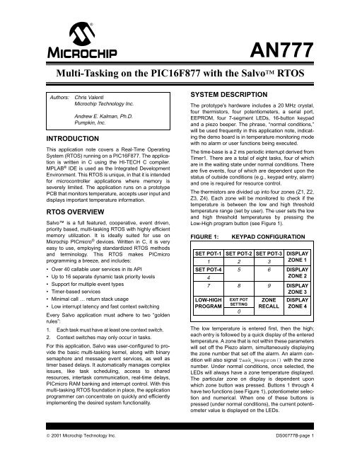
FIGURE 1: KEYPAD CONFIGURATION<br />
SET POT-1 SET POT-2 SET POT-3 DISPLAY<br />
1 2 3 ZONE 1<br />
SET POT-4 5 6 DISPLAY<br />
4<br />
ZONE 2<br />
7 8 9 DISPLAY<br />
ZONE 3<br />
LOW-HIGH<br />
PROGRAM<br />
EXIT POT<br />
SETTING<br />
ZONE<br />
RECALL<br />
DISPLAY<br />
ZONE 4<br />
The low temperature is entered first, <strong>the</strong>n <strong>the</strong> high;<br />
each entry is followed by a quick display of <strong>the</strong> entered<br />
temperature. A z<strong>on</strong>e that is not <strong>with</strong>in <strong>the</strong>se parameters<br />
will set off <strong>the</strong> Piezo alarm, simultaneously displaying<br />
<strong>the</strong> z<strong>on</strong>e number that set off <strong>the</strong> alarm. An alarm c<strong>on</strong>diti<strong>on</strong><br />
will also signal Task_Weeprom() <strong>with</strong> <strong>the</strong> z<strong>on</strong>e<br />
number. Under normal c<strong>on</strong>diti<strong>on</strong>s, <strong>on</strong>ce selected, <strong>the</strong><br />
LEDs will always have a z<strong>on</strong>e temperature displayed.<br />
The particular z<strong>on</strong>e <strong>on</strong> display is dependent up<strong>on</strong><br />
which z<strong>on</strong>e butt<strong>on</strong> was pressed. Butt<strong>on</strong>s 1 through 4<br />
have two functi<strong>on</strong>s (see Figure 1), potentiometer selecti<strong>on</strong><br />
and numerical. When <strong>on</strong>e of <strong>the</strong>se butt<strong>on</strong>s is<br />
pressed (under normal c<strong>on</strong>diti<strong>on</strong>s), <strong>the</strong> current potentiometer<br />
value is displayed <strong>on</strong> <strong>the</strong> LEDs.<br />
© 2001 <strong>Microchip</strong> Technology Inc. DS00777B-page 1<br />
0
AN777<br />
At this point, two acti<strong>on</strong>s can be taken: potentiometer<br />
adjustment, or press ‘0’ to exit <strong>the</strong> functi<strong>on</strong>. The Z<strong>on</strong>e<br />
Recall butt<strong>on</strong> is used to display <strong>the</strong> z<strong>on</strong>e that set off <strong>the</strong><br />
alarm last. The USART is used for displaying <strong>the</strong> current<br />
temperatures <strong>on</strong> a PC m<strong>on</strong>itor; this is executed by<br />
entering 'z' via <strong>the</strong> PC keyboard. The USART is c<strong>on</strong>figured<br />
for Master Asynchr<strong>on</strong>ous mode <strong>with</strong> a 9600 baud<br />
rate.<br />
APPLICATION CONFIGURATION<br />
The initial setup for <strong>the</strong> <strong>RTOS</strong> involves creating a c<strong>on</strong>figurati<strong>on</strong><br />
file and creating an MPLAB project. The<br />
<strong>Salvo</strong> user services are c<strong>on</strong>tained in different source<br />
files. As code development progresses, more user services<br />
are needed, resulting in additi<strong>on</strong>al source files<br />
being added to <strong>the</strong> applicati<strong>on</strong>. The applicati<strong>on</strong><br />
includes <strong>the</strong> following files:<br />
• main.c<br />
• binsem.c<br />
• chk.c<br />
• delay.c<br />
• event.c<br />
• init.c<br />
• mem.c<br />
• task.c<br />
• util.c<br />
• msg.c<br />
• timer.c<br />
• qins.c<br />
• salvo.h<br />
• salvocfg.h<br />
Keep in mind that <strong>the</strong>se files are specific to this applicati<strong>on</strong><br />
and may not apply to o<strong>the</strong>rs. Each <strong>Salvo</strong> applicati<strong>on</strong><br />
requires its own c<strong>on</strong>figurati<strong>on</strong> file called<br />
salvocfg.h. The default salvocfg.h file c<strong>on</strong>tains<br />
all possible parameters. For this applicati<strong>on</strong>, specific<br />
parameters were stripped out of <strong>the</strong> default file and put<br />
into a applicati<strong>on</strong> specific salvocfg.h file. This file is<br />
automatically included via <strong>the</strong> salvo.h header file.<br />
The salvocfg.h file for this applicati<strong>on</strong> is shown in<br />
Appendix B. Table 1 shows <strong>the</strong> node property settings<br />
in MPLAB IDE.<br />
MEMORY<br />
General purpose RAM is allocated to four parts of <strong>the</strong><br />
applicati<strong>on</strong>:<br />
• Global variables.<br />
• C<strong>on</strong>trol blocks and o<strong>the</strong>r variables.<br />
• Parameter stack and auto variables maintained<br />
by <strong>the</strong> compiler.<br />
• Interrupt saves and restores.<br />
The memory requirements exceed <strong>the</strong> available memory<br />
in RAM Bank 0, so <strong>the</strong> global variables are placed<br />
in Bank 1, and <strong>Salvo</strong>'s variables are placed in Bank 2,<br />
using c<strong>on</strong>figurati<strong>on</strong> opti<strong>on</strong>s in salvocfg.h. <strong>Salvo</strong>'s<br />
message pointers can access memory in any RAM<br />
bank and anywhere in ROM. The final code c<strong>on</strong>sists of<br />
three roughly equal porti<strong>on</strong>s: <strong>on</strong>e-third <strong>Salvo</strong> <strong>RTOS</strong>,<br />
<strong>on</strong>e-third HI-TECH C compiler library functi<strong>on</strong>s and<br />
<strong>on</strong>e-third applicati<strong>on</strong> specific code.<br />
TIME-BASE<br />
In an <strong>RTOS</strong> envir<strong>on</strong>ment, establishing a true time-base<br />
is critical for time-based task operati<strong>on</strong>s. In this applicati<strong>on</strong>,<br />
Timer1 triggers an interrupt every 2 ms and is<br />
solely used for this periodic interrupt. The ISR calls <strong>the</strong><br />
OSTimer() functi<strong>on</strong> and reloads Timer1 for ano<strong>the</strong>r<br />
2 ms. The 2 ms interrupt is also known as <strong>the</strong> “system<br />
tick rate” and forms <strong>the</strong> time basis for task delays. Six<br />
of <strong>the</strong> eight tasks rely <strong>on</strong> OSTimer() via OSDelay().<br />
Under normal c<strong>on</strong>diti<strong>on</strong>s, each task's run time is c<strong>on</strong>stant,<br />
thus <strong>the</strong> importance for a time-base. For<br />
instance, Task_C<strong>on</strong>vert() is c<strong>on</strong>figured to run every<br />
40 ms via "OS_Delay(20);". In <strong>the</strong> salvocfg.h<br />
include file, <strong>the</strong>re is a c<strong>on</strong>figurati<strong>on</strong> statement regarding<br />
<strong>the</strong> number of bytes allocated for delays. This c<strong>on</strong>figurati<strong>on</strong><br />
opti<strong>on</strong> tells <strong>the</strong> OS what <strong>the</strong> maximum delay<br />
can be:<br />
<strong>on</strong>e byte = 2 8-1 ticks<br />
two bytes = 2 16-1 ticks, etc.<br />
In this applicati<strong>on</strong>, we need two bytes.<br />
DS00777B-page 2 © 2001 <strong>Microchip</strong> Technology Inc.
TABLE 1: MPLAB NODE PROPERTIES<br />
NODE PROPERTIES (.c-FILES)<br />
NODE PROPERTIES (.hex-FILE)<br />
AN777<br />
© 2001 <strong>Microchip</strong> Technology Inc. DS00777B-page 3
AN777<br />
TASK CONFIGURATION<br />
Tasks and Events are <strong>the</strong> building blocks of an <strong>RTOS</strong>.<br />
These modules can be added and deleted <strong>with</strong>out<br />
affecting o<strong>the</strong>r parts of <strong>the</strong> code. This applicati<strong>on</strong> is<br />
divided into eight tasks. Under normal c<strong>on</strong>diti<strong>on</strong>s, four<br />
of <strong>the</strong> tasks are in <strong>the</strong> waiting state, while <strong>the</strong> o<strong>the</strong>r four<br />
run and <strong>the</strong>n delay <strong>the</strong>mselves repeatedly.<br />
FIGURE 2: MAIN( )<br />
START<br />
INITIALIZE<br />
SFRs<br />
INITIALIZE<br />
GLOBAL<br />
VARIABLES<br />
INITIALIZE<br />
<strong>Salvo</strong><br />
Figure 2 shows program executi<strong>on</strong> up<strong>on</strong> power-up. An<br />
important point to realize here is that <strong>on</strong>ce multi-tasking<br />
begins, <strong>the</strong> four waiting tasks do not c<strong>on</strong>sume any processing<br />
power until <strong>the</strong>y are signaled. When bringing<br />
<strong>the</strong> system <strong>on</strong>line, <strong>the</strong>re will be no alarms or user functi<strong>on</strong>s<br />
in operati<strong>on</strong>. The result is, all tasks that wait for an<br />
event will go into <strong>the</strong> waiting state and become eligible<br />
<strong>on</strong>ly when signaled.<br />
CREATE<br />
TASKS<br />
CREATE<br />
EVENTS<br />
MULTI-TASK<br />
VIA <strong>Salvo</strong>’s<br />
SCHEDULER<br />
DS00777B-page 4 © 2001 <strong>Microchip</strong> Technology Inc.
The following is a detailed descripti<strong>on</strong> of each task’s<br />
priorities, status, and resp<strong>on</strong>sibilities.<br />
Task_C<strong>on</strong>vert()<br />
Priority: 1<br />
Task has a priority of ‘1’ because we must determine<br />
<strong>the</strong>rmistor temperatures to decide whe<strong>the</strong>r an alarm<br />
c<strong>on</strong>diti<strong>on</strong> exists.<br />
Status: Runs every 40 millisec<strong>on</strong>ds.<br />
Resp<strong>on</strong>sibilities:<br />
1. C<strong>on</strong>verts <strong>the</strong> analog <strong>the</strong>rmistor voltage into a<br />
digital value, <strong>the</strong>n translates this value into a<br />
Fahrenheit temperature.<br />
2. This value is compared against <strong>the</strong> low and high<br />
threshold temperatures [via C<strong>on</strong>vertTemp()]<br />
to determine if an alarm is necessary.<br />
3. If no alarm is called <strong>the</strong>n <strong>the</strong> o<strong>the</strong>r <strong>the</strong>rmistor<br />
z<strong>on</strong>es are c<strong>on</strong>verted.<br />
Task_Alarm_On()<br />
Priority: 1<br />
This task also has a priority of ‘1’, but runs after<br />
Task_C<strong>on</strong>vert() in a round-robin fashi<strong>on</strong>. After<br />
determining temperature, checking for z<strong>on</strong>e alarms is<br />
most important.<br />
Status: Waits for an event.<br />
Resp<strong>on</strong>sibilities:<br />
1. Has <strong>the</strong> same priority as, and runs immediately<br />
after, Task_C<strong>on</strong>vert()at start-up.<br />
2. Displays <strong>the</strong> z<strong>on</strong>e number in alarm.<br />
3. Turns <strong>the</strong> piezo beeper <strong>on</strong> and off.<br />
Task_Display()<br />
Priority: 2<br />
Enables temperatures to be read from <strong>the</strong> display.<br />
Status: Runs every 2 millisec<strong>on</strong>ds.<br />
Resp<strong>on</strong>sibilities:<br />
1. C<strong>on</strong>verts <strong>the</strong> temperature value to a format necessary<br />
for displaying <strong>on</strong> <strong>the</strong> LEDs.<br />
2. Displays each c<strong>on</strong>verted digit.<br />
Task_KeyPad()<br />
Priority: 3<br />
Keypad entry is infrequent and should not supercede<br />
<strong>the</strong> prior tasks.<br />
Status: Runs every 20 millisec<strong>on</strong>ds.<br />
Resp<strong>on</strong>sibilities:<br />
1. Scans for <strong>the</strong> low-high entry.<br />
2. Scans for potentiometer adjustment entry.<br />
3. Scans for EEPROM recall entry.<br />
4. Scans for z<strong>on</strong>e display entry.<br />
Task_Usart()<br />
AN777<br />
Priority: 4<br />
Remote PC m<strong>on</strong>itoring is <strong>on</strong>ly performed occasi<strong>on</strong>ally<br />
because usage is low.<br />
Status: Runs every 800 millisec<strong>on</strong>ds.<br />
Resp<strong>on</strong>sibilities:<br />
1. Scans for a PC keyboard entry (z).<br />
2. Prepares each z<strong>on</strong>e temperature for PC m<strong>on</strong>itor<br />
display.<br />
3. Writes <strong>the</strong> Z1 string out to <strong>the</strong> HyperTerminal via<br />
<strong>the</strong> USART.<br />
Task_Weeprom()<br />
Priority: 5<br />
This task is <strong>on</strong>ly active when an alarm has occurred;<br />
<strong>the</strong>refore, it is used very little.<br />
Status: Waits for an event.<br />
Resp<strong>on</strong>sibilities:<br />
1. Receives <strong>the</strong> z<strong>on</strong>e number in alarm.<br />
2. Writes z<strong>on</strong>e number to EEPROM.<br />
3. I 2C communicati<strong>on</strong> between <strong>the</strong> microc<strong>on</strong>troller<br />
and EEPROM.<br />
Task_Reeprom()<br />
Priority: 6<br />
This task is dependent up<strong>on</strong> Task_KeyPad() and is<br />
independent of temperature and alarm status; <strong>the</strong>refore,<br />
it is a very low priority.<br />
Status: Waits for an event.<br />
Resp<strong>on</strong>sibilities:<br />
1. Reads <strong>the</strong> last address that Task_Weeprom()<br />
wrote to.<br />
2. Reads <strong>the</strong> data <strong>with</strong>in this address.<br />
3. Displays <strong>the</strong> c<strong>on</strong>tents of <strong>the</strong> EEPROM address<br />
<strong>on</strong> <strong>the</strong> LEDs (z<strong>on</strong>e number).<br />
Task_Pots()<br />
Priority: 7<br />
This task is least important because it is <strong>on</strong>ly used for<br />
setting potentiometers, which do not affect any temperature<br />
or alarm statuses.<br />
Status: Waits for an event.<br />
Resp<strong>on</strong>sibilities:<br />
1. According to <strong>the</strong> value passed to <strong>the</strong> local variable<br />
pot_val, <strong>the</strong> appropriate pot is selected for<br />
adjustment while displaying <strong>the</strong> current potentiometer<br />
A/D value <strong>on</strong> <strong>the</strong> LEDs.<br />
© 2001 <strong>Microchip</strong> Technology Inc. DS00777B-page 5
AN777<br />
EVENT CONFIGURATION<br />
Semaphores and messages can represent events and<br />
<strong>the</strong>se methods of intertask communicati<strong>on</strong> are used in<br />
two ways. The first and more obvious is d<strong>on</strong>e by signaling<br />
tasks. When a task is signaled, it transiti<strong>on</strong>s from a<br />
waiting state to an eligible state and finally a running<br />
state. ALARM, REEPROM, POTVAL and WEEPROM are<br />
used in this fashi<strong>on</strong>. The DISPLAY event is used to<br />
c<strong>on</strong>trol a resource, quite different from <strong>the</strong> o<strong>the</strong>r<br />
events. Because <strong>the</strong> LED display is used by multiple<br />
tasks and <strong>the</strong> LEDs and keypad both operate out of<br />
PORTB <strong>on</strong> <strong>the</strong> microc<strong>on</strong>troller, PORTB has to be c<strong>on</strong>figured<br />
differently for both. The DISPLAY event is used<br />
to manage access to PORTB. When c<strong>on</strong>trol of<br />
DISPLAY is placed around a group of statements, it<br />
creates a sequence whereby a resource is acquired,<br />
used, and <strong>the</strong>n released.<br />
The process flow for Task_Alarm_On(), has <strong>the</strong> task<br />
in <strong>on</strong>e of three states: running, delayed, or waiting for an<br />
event. <strong>Salvo</strong> manages task executi<strong>on</strong> so <strong>the</strong> PICmicro<br />
always runs <strong>the</strong> highest priority, eligible task. Whenever<br />
a particular task is running in this applicati<strong>on</strong>, all o<strong>the</strong>r<br />
tasks are ei<strong>the</strong>r delayed, waiting for an event, or eligible<br />
to run.<br />
Looking at Task_Alarm_On()when <strong>the</strong> code reaches<br />
OS_WaitBinSem (DISPLAY), if DISPLAY = 1, <strong>the</strong>n<br />
OS_WaitBinSem() flips it to ‘0’, and <strong>the</strong> following<br />
code is executed. When <strong>Salvo</strong> c<strong>on</strong>text switches via<br />
OS_Delay(), any piece of <strong>the</strong> code that waits for<br />
DISPLAY will not run (DISPLAY = 0). After both<br />
Task_Alarm_ON() and OS_Delay() are completed,<br />
DISPLAY is signaled (DISPLAY = 1) and allows <strong>the</strong><br />
next piece of code waiting for DISPLAY to run.<br />
ALARM<br />
Type: Message<br />
Purpose: Signal Task_Alarm_On() from <strong>with</strong>in<br />
Task_C<strong>on</strong>vert()(C<strong>on</strong>vertTemp()), <strong>with</strong> a message<br />
c<strong>on</strong>taining <strong>the</strong> z<strong>on</strong>e number in alarm.<br />
WEEPROM<br />
Type: Message<br />
Purpose: Signal Task_Weeprom() <strong>with</strong> a message<br />
c<strong>on</strong>taining <strong>the</strong> z<strong>on</strong>e number in alarm. This message<br />
<strong>on</strong>ly happens if <strong>the</strong>re is an alarm and after <strong>the</strong> signaling<br />
of Task_Alarm_On().<br />
REEPROM<br />
Type: Binary Semaphore<br />
Purpose: Signal Task_Reeprom() from <strong>with</strong>in<br />
Task_KeyPad() that <strong>the</strong> read EEPROM butt<strong>on</strong> has<br />
been pressed. Signaling <strong>the</strong> binary semaphore causes<br />
<strong>the</strong> waiting task to run.<br />
POTVAL<br />
Type: Message<br />
Purpose: Signal Task_Pots() from <strong>with</strong>in<br />
Task_KeyPad() that a potentiometer adjustment butt<strong>on</strong><br />
has been pressed. Passes informati<strong>on</strong> c<strong>on</strong>taining<br />
<strong>the</strong> potentiometer number to set for adjustment mode.<br />
DISPLAY<br />
Type: Binary Semaphore<br />
Purpose: This semaphore is used to c<strong>on</strong>trol a<br />
resource, this may be <strong>the</strong> functi<strong>on</strong> of <strong>the</strong> LEDs or <strong>the</strong><br />
keypad.<br />
TIMING PERFORMANCE<br />
Time management is a major resp<strong>on</strong>sibility for an<br />
<strong>RTOS</strong>. An applicati<strong>on</strong>'s resp<strong>on</strong>se is dependent up<strong>on</strong><br />
task executi<strong>on</strong> times. The actual time between successive<br />
executi<strong>on</strong>s of Task_C<strong>on</strong>vert() was measured<br />
as 40 millisec<strong>on</strong>ds, <strong>with</strong> less than <strong>on</strong>e system tick<br />
(2 ms) of timing jitter. When task delay times are calculated,<br />
<strong>the</strong> time necessary for instructi<strong>on</strong>s <strong>with</strong>in <strong>the</strong> task<br />
must also be taken into c<strong>on</strong>siderati<strong>on</strong>.<br />
SUMMARY<br />
This applicati<strong>on</strong> note dem<strong>on</strong>strates how easy it is to<br />
implement a comm<strong>on</strong> embedded applicati<strong>on</strong> into an<br />
<strong>RTOS</strong> envir<strong>on</strong>ment. The temperature applicati<strong>on</strong><br />
shown here is just <strong>on</strong>e of <strong>the</strong> many ways in which an<br />
<strong>RTOS</strong> can be applied. Some <strong>RTOS</strong> features that have<br />
not been discussed may be what your applicati<strong>on</strong><br />
requires. This includes counting semaphores and message<br />
queues, which are extended versi<strong>on</strong>s of <strong>the</strong> user<br />
services used in this applicati<strong>on</strong>. Only <strong>on</strong>e interrupt<br />
was used (to maintain a time-base), but additi<strong>on</strong>al<br />
interrupt sources can be included for added real-time<br />
resp<strong>on</strong>se. After establishing an understanding of <strong>RTOS</strong><br />
user services, it's just a matter of adding more tasks<br />
and events to suit <strong>the</strong> demands of your applicati<strong>on</strong>.<br />
WEBSITES<br />
<strong>Microchip</strong> Technology Inc. ............ www.microchip.com<br />
Pumpkin, Inc.............................. www.pumpkininc.com<br />
HI-TECH Software...............................www.htsoft.com<br />
DS00777B-page 6 © 2001 <strong>Microchip</strong> Technology Inc.
APPENDIX A: FLOW CHARTS<br />
FIGURE A-1: SCHEMATIC (SHEET 1 OF 3)<br />
+5 V<br />
+5 V<br />
R9<br />
10 k<br />
C8<br />
.1 µF<br />
J13<br />
R12<br />
10 k<br />
+5 V<br />
1<br />
3<br />
2<br />
DJ005B<br />
SCL<br />
R24<br />
R25<br />
100<br />
100<br />
8 VCC<br />
6 SCL<br />
7 WP<br />
4 GND<br />
C7<br />
AN2<br />
220 µF<br />
U2<br />
24LC01B<br />
+5 V<br />
+5 V<br />
C4<br />
.1 µF<br />
+5 V<br />
R23<br />
100<br />
SDA<br />
AN1<br />
R11 R26<br />
AN3<br />
10 k 100<br />
RXD<br />
TXD<br />
SDA<br />
A0<br />
A1<br />
A2<br />
R10<br />
10 k<br />
1 IN<br />
5<br />
1<br />
2<br />
3<br />
VR1<br />
LM340T-5.0<br />
COM<br />
2<br />
1 RXOUT<br />
2 VDRV<br />
3 TXIN<br />
4 GND<br />
OUT<br />
U13<br />
DS275_SO8<br />
AN0<br />
3<br />
VCC<br />
RXIN<br />
NC<br />
TXOUT<br />
8<br />
7<br />
6<br />
5<br />
C5<br />
.1 µF<br />
AN777<br />
© 2001 <strong>Microchip</strong> Technology Inc. DS00777B-page 7<br />
+5 V<br />
C14<br />
.1 µF<br />
C11<br />
.1 µF<br />
R3<br />
470<br />
+5 V<br />
C6<br />
.1 µF<br />
+5 V<br />
+5 V<br />
R29<br />
R17<br />
10 k<br />
R28<br />
R16<br />
10 k<br />
D2<br />
R18<br />
100<br />
R15<br />
100<br />
PIZO<br />
1<br />
2<br />
3<br />
4<br />
5<br />
J14<br />
PIN1<br />
PIN6<br />
PIN2<br />
PIN7<br />
PIN3<br />
PIN8<br />
PIN4<br />
PIN9<br />
PIN5<br />
6<br />
7<br />
8<br />
9<br />
DE9S-FRS<br />
C16<br />
.1 µF<br />
SP1<br />
+5 V<br />
+5 V<br />
R30<br />
R20<br />
AN5 AN6<br />
100<br />
C15 R19<br />
10 k<br />
.1 µF<br />
AN4<br />
R31<br />
R22<br />
100<br />
R21<br />
10 k<br />
AN7
AN777<br />
FIGURE A-2: SCHEMATIC (SHEET 2 OF 3)<br />
1<br />
2<br />
S2<br />
R1<br />
4.7 k<br />
4<br />
3<br />
C1<br />
.1 µF<br />
+5 V<br />
+5 V<br />
C2<br />
.1 µF<br />
C3<br />
.1 µF<br />
MCLR<br />
AN0<br />
AN1<br />
AN2<br />
AN3<br />
AN4<br />
RB0<br />
RB1<br />
RB2<br />
RB3<br />
RB4<br />
RB5<br />
RB6<br />
RB7<br />
11 VDD<br />
32 VDD<br />
1 MCLR<br />
2 RA0<br />
3 RA1<br />
4 RA2<br />
5 RA3<br />
6 RA4<br />
7 RA5<br />
33 RB0<br />
34 RB1<br />
35 RB2<br />
36 RB3<br />
37 RB4<br />
38 RB5<br />
39 RB6<br />
40 RB7<br />
12 VSS<br />
31 VSS<br />
R27 1 k<br />
20 MHz<br />
DS00777B-page 8 © 2001 <strong>Microchip</strong> Technology Inc.<br />
U1<br />
<strong>PIC16F877</strong><br />
RE2<br />
RE1<br />
RE0<br />
RD7<br />
RD6<br />
RD5<br />
RD4<br />
RD3<br />
RD2<br />
RD1<br />
RD0<br />
RC7<br />
RC6<br />
RC5<br />
RC4<br />
RC3<br />
RC2<br />
RC1<br />
RC0<br />
OSC2<br />
OSC1<br />
10<br />
9<br />
8<br />
30<br />
29<br />
28<br />
27<br />
22<br />
21<br />
20<br />
19<br />
26<br />
25<br />
24<br />
23<br />
18<br />
17<br />
16<br />
15<br />
14<br />
13<br />
AN7<br />
AN6<br />
AN5<br />
RD3<br />
RD2<br />
RD1<br />
RD0<br />
RXD<br />
TXD<br />
C18<br />
15 pF<br />
C19<br />
15 pF<br />
Y1<br />
+5 V +5 V<br />
R2<br />
4.7 k<br />
32 kHz<br />
Y2<br />
C17<br />
15 pF<br />
R4<br />
PIZO<br />
4.7 k<br />
SDA<br />
SCL<br />
C20<br />
15 pF
FIGURE A-3: SCHEMATIC (SHEET 3 OF 3)<br />
RB0<br />
RB1<br />
RB2<br />
RB3<br />
RB4<br />
RB5<br />
RB6<br />
RB7<br />
J1<br />
RN1:1<br />
2 1<br />
3 4<br />
6 5<br />
8 7<br />
2 1<br />
4 3<br />
6 5<br />
8 7<br />
220<br />
1<br />
2<br />
3<br />
4<br />
5<br />
6<br />
7<br />
8<br />
9<br />
C4<br />
C3<br />
C2<br />
C1<br />
DP<br />
G<br />
F<br />
E<br />
10<br />
A a<br />
9<br />
B b<br />
8<br />
C c<br />
5<br />
D d<br />
4<br />
E e<br />
2<br />
F f<br />
3<br />
G g<br />
7<br />
DP dp<br />
D1<br />
1<br />
anode 6<br />
anode<br />
10<br />
A a<br />
9<br />
B b<br />
8<br />
C c<br />
5<br />
D d<br />
4<br />
E e<br />
2<br />
F f<br />
3<br />
G g<br />
7<br />
DP dp<br />
D3<br />
1<br />
anode 6<br />
anode<br />
10<br />
A a<br />
9<br />
B b<br />
8<br />
C c<br />
5<br />
D d<br />
4<br />
E e<br />
2<br />
F f<br />
3<br />
G g<br />
7<br />
DP dp<br />
1<br />
anode 6<br />
anode<br />
RD0<br />
HDSP-7301<br />
R8<br />
Q1<br />
2<br />
3<br />
RD1<br />
HDSP-7301<br />
R7<br />
Q2<br />
2<br />
3<br />
RD2<br />
HDSP-7301<br />
R5<br />
Q3<br />
2<br />
3<br />
RD3<br />
1k<br />
2N3906 1<br />
1k<br />
2N3906 1<br />
1k<br />
2N3906 1<br />
+5 V<br />
RB0<br />
RN3:4<br />
RB1<br />
RB2<br />
RB3<br />
2<br />
4<br />
6<br />
RN3:1<br />
100 k<br />
RN3:2<br />
100 k<br />
RN3:3<br />
100 k<br />
4 3<br />
6 5<br />
8 7<br />
10 k<br />
1<br />
3<br />
5<br />
RN4:1<br />
2 1<br />
8 7<br />
AN777<br />
HDSP-7301<br />
Q4<br />
R6<br />
2<br />
2N3906 1<br />
+5 V +5 V +5 V +5 V<br />
E<br />
F<br />
G<br />
C1<br />
DP<br />
C2<br />
C3<br />
C4<br />
1<br />
2<br />
1<br />
2<br />
1<br />
2<br />
1<br />
2<br />
S3<br />
S7<br />
S11<br />
S15<br />
4<br />
3<br />
4<br />
3<br />
4<br />
3<br />
4<br />
3<br />
© 2001 <strong>Microchip</strong> Technology Inc. DS00777B-page 9<br />
1<br />
2<br />
1<br />
2<br />
1<br />
2<br />
1<br />
2<br />
S4<br />
S8<br />
S12<br />
S16<br />
4<br />
3<br />
4<br />
3<br />
4<br />
3<br />
4<br />
3<br />
D4<br />
1<br />
2<br />
1<br />
2<br />
1<br />
2<br />
1<br />
2<br />
S5<br />
S9<br />
S13<br />
S17<br />
10<br />
A a<br />
9<br />
B b<br />
8<br />
C c<br />
5<br />
D d<br />
4<br />
E e<br />
2<br />
F f<br />
3<br />
G g<br />
7<br />
DP dp<br />
4<br />
3<br />
4<br />
3<br />
4<br />
3<br />
4<br />
3<br />
1<br />
2<br />
1<br />
2<br />
1<br />
2<br />
1<br />
2<br />
D5<br />
1k<br />
1<br />
anode 6<br />
anode<br />
S6<br />
S10<br />
S14<br />
S18<br />
4<br />
3<br />
4<br />
3<br />
4<br />
3<br />
4<br />
3<br />
3
Software License Agreement<br />
AN777<br />
The software supplied here<strong>with</strong> by <strong>Microchip</strong> Technology Incorporated (<strong>the</strong> “Company”) for its PICmicro® Microc<strong>on</strong>troller is<br />
intended and supplied to you, <strong>the</strong> Company’s customer, for use solely and exclusively <strong>on</strong> <strong>Microchip</strong> PICmicro Microc<strong>on</strong>troller products.<br />
The software is owned by <strong>the</strong> Company and/or its supplier, and is protected under applicable copyright laws. All rights are reserved.<br />
Any use in violati<strong>on</strong> of <strong>the</strong> foregoing restricti<strong>on</strong>s may subject <strong>the</strong> user to criminal sancti<strong>on</strong>s under applicable laws, as well as to civil<br />
liability for <strong>the</strong> breach of <strong>the</strong> terms and c<strong>on</strong>diti<strong>on</strong>s of this license.<br />
THIS SOFTWARE IS PROVIDED IN AN “AS IS” CONDITION. NO WARRANTIES, WHETHER EXPRESS, IMPLIED OR STATU-<br />
TORY, INCLUDING, BUT NOT LIMITED TO, IMPLIED WARRANTIES OF MERCHANTABILITY AND FITNESS FOR A PARTICU-<br />
LAR PURPOSE APPLY TO THIS SOFTWARE. THE COMPANY SHALL NOT, IN ANY CIRCUMSTANCES, BE LIABLE FOR<br />
SPECIAL, INCIDENTAL OR CONSEQUENTIAL DAMAGES, FOR ANY REASON WHATSOEVER.<br />
APPENDIX B: SOURCE CODE<br />
salvocfg.h<br />
#define OSCOMPILER OSHT_PICC<br />
#define OSTARGET OSPIC16<br />
#define OSBYTES_OF_DELAYS 2<br />
#define OSLOC_ECB bank2<br />
#define OSLOC_TCB bank2<br />
#define OSEVENTS 5<br />
#define OSTASKS 8<br />
#define OSENABLE_BINARY_SEMAPHORES TRUE<br />
#define OSENABLE_MESSAGES TRUE<br />
#define OSBIG_MESSAGE_POINTERS TRUE<br />
main.c<br />
/*<br />
This program is based <strong>on</strong> <strong>the</strong> <strong>Salvo</strong> <strong>RTOS</strong> (v2.1). Its functi<strong>on</strong> is to scan<br />
four <strong>the</strong>rmistors and report <strong>the</strong>ir temperatures. If any of reported temperatures<br />
are not <strong>with</strong>in a preset range, <strong>the</strong> alarm will sound. Four potentiometers adjustments<br />
are accessed via keypad entry. Two of <strong>the</strong>m will be used to determine <strong>the</strong> Piezo t<strong>on</strong>e and<br />
duty cycle, while <strong>the</strong>se pots are being set <strong>the</strong>ir A/D values will appear <strong>on</strong> <strong>the</strong> LED display.<br />
The four <strong>the</strong>rmistor are divided up into 4 z<strong>on</strong>es, each z<strong>on</strong>e can be displayed <strong>on</strong> <strong>the</strong><br />
4-digit LED display via a keypad entry. The defined temperature range can be entered by keypad<br />
entry, entering <strong>the</strong> LOW temp first followed by <strong>the</strong> HIGH temp. Z<strong>on</strong>e temperatures can be recalled<br />
<strong>on</strong>to a PC m<strong>on</strong>itor via <strong>the</strong> HyperTerminal by pressing ’z’ <strong>on</strong> a PC keyboard.<br />
Every time a z<strong>on</strong>e goes into alarm, <strong>the</strong> alarm z<strong>on</strong>e number will be written to <strong>the</strong><br />
EEPROM. The z<strong>on</strong>e that last set off an alarm can be recalled via keypad entry and <strong>the</strong><br />
z<strong>on</strong>e number will be displayed.<br />
*/<br />
#include <br />
#define ALARM 0<br />
#define WEEPROM 1<br />
#define REEPROM 2<br />
#define POTVAL 3<br />
#define DISPLAY 4<br />
static volatile unsigned int TMR1 @ 0x0E;<br />
bank1 unsigned char Low_Hi;<br />
bank1 signed char data_address; //EEPROM ADDRESS<br />
bank1 unsigned char *z<strong>on</strong>e_dis; //ZONE DISPLAY<br />
bank1 unsigned char temp1, temp2, temp3, temp4; //ALARM & ZONE TEMPS<br />
bank1 unsigned char low, high; //LOW & HIGH TEMP THRESHOLD<br />
© 2001 <strong>Microchip</strong> Technology Inc. DS00777B-page 10
AN777<br />
bank1 unsigned char Z1[39] = "ZONE Temps: z1-xx z2-xx z3-xx z4-xx\n\r\v";//RS-232 DISPLAY<br />
c<strong>on</strong>st char SevenSegmentTable[] = //DIGIT SEGMENTS<br />
{ 0b11000000, // 0<br />
0b11111001, // 1<br />
0b10100100, // 2<br />
0b10110000, // 3<br />
0b10011001, // 4<br />
0b10010010, // 5<br />
0b10000010, // 6<br />
0b11111000, // 7<br />
0b10000000, // 8<br />
0b10010000 // 9<br />
};<br />
c<strong>on</strong>st unsigned char CHSmask[] = //A/D CHS BITS<br />
{ 0b00100000,<br />
0b00101000,<br />
0b00110000,<br />
0b00111000<br />
};<br />
c<strong>on</strong>st unsigned char z<strong>on</strong>es[] = //TEMPERATURE ZONE NUMBERS<br />
{<br />
1,<br />
2,<br />
3,<br />
4<br />
};<br />
bank1 unsigned char * c<strong>on</strong>st tempPArray [] = //ZONE TEMPERATURES<br />
{<br />
&temp1,<br />
&temp2,<br />
&temp3,<br />
&temp4<br />
};<br />
//PROTOTYPES<br />
void Delay(unsigned char tmr);<br />
void interrupt isr(void);<br />
void C<strong>on</strong>vertAD(void);<br />
char Butt<strong>on</strong>Press(unsigned char butt<strong>on</strong>s);<br />
char Keys(void);<br />
void BcdC<strong>on</strong>v(char);<br />
void WriteSevenSegment( unsigned char segment, unsigned char digit);<br />
char ReadUSART(void);<br />
void WriteUSART(char data);<br />
void WriteUSARTBuffer(unsigned char *data, unsigned char len);<br />
void Idle(void);<br />
void Display(unsigned char lo_hi);<br />
void PotDisplay(void);<br />
void C<strong>on</strong>vertTemp( bank1 unsigned char * c<strong>on</strong>st temp,<br />
c<strong>on</strong>st unsigned char * z<strong>on</strong>e );<br />
_OSLabel (task_c<strong>on</strong>vert1)<br />
_OSLabel (task_alarm_<strong>on</strong>1)<br />
_OSLabel (task_alarm_<strong>on</strong>2)<br />
_OSLabel (task_alarm_<strong>on</strong>3)<br />
_OSLabel (task_alarm_<strong>on</strong>4)<br />
_OSLabel (task_keypad1)<br />
_OSLabel (task_keypad2)<br />
_OSLabel (task_keypad3)<br />
_OSLabel (task_display1)<br />
_OSLabel (task_display2)<br />
© 2001 <strong>Microchip</strong> Technology Inc. DS00777B-page 11
AN777<br />
_OSLabel (task_usart1)<br />
_OSLabel (task_weeprom1)<br />
_OSLabel (task_reeprom1)<br />
_OSLabel (task_reeprom2)<br />
_OSLabel (task_reeprom3)<br />
_OSLabel (task_pots1)<br />
_OSLabel (task_pots2)<br />
//**************************( FUNCTIONS )****************************************<br />
void Delay(unsigned char tmr) //TIMER0 MAX TIMEOUT = 13ms<br />
{<br />
TMR0 = 255 - tmr;<br />
T0IF = 0;<br />
while(T0IF==0);<br />
}<br />
#pragma interrupt_level 0<br />
void interrupt isr(void) //TIMER1 2ms PERIODIC INTERRUPT<br />
{<br />
if(TMR1IF)<br />
{<br />
TMR1IF = 0;<br />
TMR1 -= 5000;<br />
OSTimer();<br />
}<br />
}<br />
void C<strong>on</strong>vertAD(void) //A/D CONVERSION<br />
{<br />
Delay(1);<br />
ADGO = 1;<br />
while(ADGO);<br />
}<br />
char Butt<strong>on</strong>Press(unsigned char butt<strong>on</strong>s)<br />
{<br />
unsigned char Col_Row; //FIND BUTTON PRESS<br />
PORTB = butt<strong>on</strong>s;<br />
Delay(55);<br />
Col_Row = PORTB;<br />
return Col_Row;<br />
}<br />
char Keys(void) //NUMBER SELECTION<br />
{<br />
char KeyVal = 10; //BUTTON NUMBER PRESSED<br />
PORTD = 0x0F; //LEDs OFF<br />
TRISB = 0xF0; //RB7:RB4=INPUTS,RB3:RB0=OUTPUTS<br />
while(KeyVal == 10)<br />
{<br />
switch(Butt<strong>on</strong>Press(0b00001110))<br />
{<br />
case 0xEE:<br />
KeyVal = 0b00000001; //#1<br />
break;<br />
case 0xDE:<br />
KeyVal = 0b00000100; //#4<br />
break;<br />
DS00777B-page 12 © 2001 <strong>Microchip</strong> Technology Inc.
}<br />
case 0xBE:<br />
KeyVal = 0b00000111; //#7<br />
break;<br />
default:<br />
break;<br />
}<br />
switch(Butt<strong>on</strong>Press(0b00001101))<br />
{<br />
case 0xED:<br />
KeyVal = 0b00000010; //#2<br />
break;<br />
case 0xDD:<br />
KeyVal = 0b00000101; //#5<br />
break;<br />
case 0xBD:<br />
KeyVal = 0b00001000; //#8<br />
break;<br />
case 0x7D:<br />
KeyVal = 0; //#0<br />
break;<br />
default:<br />
break;<br />
}<br />
switch(Butt<strong>on</strong>Press(0b00001011))<br />
{<br />
case 0xEB:<br />
KeyVal = 0b00000011; //#3<br />
break;<br />
case 0xDB:<br />
KeyVal = 0b00000110; //#6<br />
break;<br />
case 0xBB:<br />
KeyVal = 0b00001001; //#9<br />
break;<br />
default:<br />
break;<br />
}<br />
PORTB = 0b00000000;<br />
}return KeyVal;<br />
void BcdC<strong>on</strong>v(char KeyVal) //BCD CONVERSION<br />
{<br />
Low_Hi *= 10;<br />
Low_Hi += KeyVal;<br />
}<br />
void WriteSevenSegment(unsigned char segment, unsigned char digit)<br />
{ //LED VALUE DISPLAY<br />
switch(digit)<br />
{<br />
case 1:<br />
PORTD = 0x0E; //FIRST DIGIT<br />
break;<br />
AN777<br />
© 2001 <strong>Microchip</strong> Technology Inc. DS00777B-page 13
AN777<br />
}<br />
case 2:<br />
PORTD = 0x0D; //SECOND DIGIT<br />
break;<br />
case 3:<br />
PORTD = 0x0B; //THIRD DIGIT<br />
break;<br />
case 4:<br />
PORTD = 0x07; //FOURTH DIGIT<br />
break;<br />
}<br />
TRISB = 0x00;<br />
PORTB = SevenSegmentTable[segment]; //SEND SEGMENT NUMBER TO PORTB<br />
char ReadUSART(void) //READ SERIAL DATA ENTRY<br />
{<br />
unsigned char rdata;<br />
if(RCIF) //RECEPTION COMPLETE<br />
rdata = RCREG;<br />
return rdata;<br />
}<br />
void WriteUSART(char data) //WRITE SERIAL DATA<br />
{<br />
while(!TRMT);<br />
TXREG = data;<br />
}<br />
void WriteUSARTBuffer(unsigned char *data, unsigned char len)<br />
{<br />
unsigned char i;<br />
}<br />
for ( i = 0; i < len; i++ )<br />
WriteUSART(data[i]); //WRITE STRING<br />
void Idle(void) //I2C IDLE FUNCTION<br />
{<br />
while((SSPCON2 & 0x1F)|(STAT_RW))<br />
c<strong>on</strong>tinue;<br />
}<br />
void Display(unsigned char lo_hi) //DISPLAY LOW & HIGH INPUT<br />
{<br />
unsigned char v1,v2,v3;<br />
unsigned char i;<br />
for(i=1; i
}<br />
Delay(55);<br />
WriteSevenSegment(v3, 4);<br />
Delay(55);<br />
}<br />
void PotDisplay(void)<br />
{<br />
unsigned char v1,v2,v3;<br />
for(;;)<br />
{<br />
C<strong>on</strong>vertAD();<br />
v1 = ADRESH/0x64; //FIND FIRST DISPLAY DIGIT<br />
v2 = (ADRESH-(v1*0x64))/10; //FIND SECOND DIGIT<br />
v3 = (ADRESH-(v1*0x64)-(v2*10)); //FIND THIRD DIGIT ;<br />
WriteSevenSegment(v1, 2); //SEND SEGMENT VALUE AND DIGIT 2<br />
Delay(15);<br />
WriteSevenSegment(v2, 3); //SEND SEGMENT VALUE AND DIGIT 3<br />
Delay(15);<br />
WriteSevenSegment(v3, 4); //SEND SEGMENT VALUE AND DIGIT 4<br />
Delay(15);<br />
}<br />
}<br />
PORTD = 0x0F; //PREPARE FOR KEYPAD USE<br />
TRISB = 0xF0;<br />
if(Butt<strong>on</strong>Press(0b00001101) == 0x7D)<br />
break;<br />
void C<strong>on</strong>vertTemp( bank1 unsigned char * c<strong>on</strong>st temp, c<strong>on</strong>st unsigned char * z<strong>on</strong>e )<br />
{ float adresh;<br />
adresh = ADRESH;<br />
*temp = ( (.538) + (.444*(adresh) ) + (.001*(adresh)*(adresh) ) );<br />
}<br />
if ( ( low > *temp ) || ( *temp > high ) )<br />
{<br />
OSSignalMsg(ALARM, (OStypeMsgP) z<strong>on</strong>e); //SIGNAL task_alarm() W/ ZONE #<br />
OSSignalMsg(WEEPROM, (OStypeMsgP) z<strong>on</strong>e); //SIGNAL task_weeprom() W/ ZONE #<br />
}<br />
//**************************( TASKS )*******************************************<br />
//**********************************************************************************<br />
void Task_C<strong>on</strong>vert(void)<br />
{<br />
static unsigned char i = 0;<br />
}<br />
for(;;)<br />
{<br />
ADCON0 &= ~0b00111000; //CLEAR CHS BITS<br />
ADCON0 |= CHSmask[i]; //SELECT CHS<br />
C<strong>on</strong>vertAD(); //CONVERT CHS<br />
C<strong>on</strong>vertTemp(tempPArray[i], &z<strong>on</strong>es[i] );<br />
}<br />
if ( ++i > 3 ) i = 0;<br />
OS_Delay(20,task_c<strong>on</strong>vert1); //DELAYED FOR 40ms<br />
AN777<br />
© 2001 <strong>Microchip</strong> Technology Inc. DS00777B-page 15
AN777<br />
void Task_Alarm_On(void) //WAITING TASK<br />
{<br />
OStypeMsgP msgP;<br />
}<br />
for(;;)<br />
{<br />
OS_WaitMsg(ALARM, &msgP, task_alarm_<strong>on</strong>1);<br />
OS_WaitBinSem(DISPLAY, task_alarm_<strong>on</strong>2);<br />
WriteSevenSegment(* ( c<strong>on</strong>st unsigned char *) msgP, 4);//DISPLAY ALARM ZONE<br />
CCP1CON = 0x0F;<br />
OS_Delay(200, task_alarm_<strong>on</strong>3);<br />
CCP1CON = 0;<br />
OS_Delay(200, task_alarm_<strong>on</strong>4);<br />
OSSignalBinSem(DISPLAY);<br />
}<br />
void Task_Keypad(void)<br />
{<br />
static char pot;<br />
for(;;)<br />
{<br />
OS_WaitBinSem(DISPLAY, task_keypad1);<br />
PORTD = 0x0F; //LEDs OFF<br />
TRISB = 0xF0; //RB7:RB4 = INPUTS,RB3:RB0 = OUTPUTS<br />
switch(Butt<strong>on</strong>Press(0b00001110) )<br />
{<br />
case 0x7E: //SET LOW AND HIGH TEMPS<br />
PORTD = 0x00; //TURN ON DIGITS TO<br />
TRISB = 0x00; // SHOW TEMP SETTING<br />
PORTB = 0x00; // ACTIVATION<br />
OS_Delay(200, task_keypad2);<br />
//GET LOW TEMPERATURE LIMIT<br />
PEIE = 0; //INTERRUPT DISABLED<br />
Low_Hi = 0;<br />
BcdC<strong>on</strong>v(Keys()); //GET 1ST DIGIT<br />
while( PORTB != 0xF0 );<br />
BcdC<strong>on</strong>v(Keys()); //GET 2ND DIGIT<br />
while( PORTB != 0xF0 );<br />
BcdC<strong>on</strong>v(Keys()); //GET 3RD DIGIT<br />
low = Low_Hi;<br />
Display(low); //DISPLAY LOW TEMP<br />
PORTD = 0x0F; //LEDs OFF<br />
TRISB = 0xF0; //RB7:RB4 = INPUTS,RB3:RB0 = OUTPUTS<br />
//GET HIGH TEMPERATURE LIMIT<br />
Low_Hi = 0;<br />
BcdC<strong>on</strong>v(Keys()); //GET 1ST DIGIT<br />
while( PORTB != 0xF0 );<br />
BcdC<strong>on</strong>v(Keys()); //GET 2ND DIGIT<br />
while( PORTB != 0xF0 );<br />
BcdC<strong>on</strong>v(Keys()); //GET 3RD DIGIT<br />
high = Low_Hi;<br />
Display(high); //DISPLAY HIGH TEMP<br />
PEIE = 1; //INTERRUPT RE-ENABLED<br />
break;<br />
DS00777B-page 16 © 2001 <strong>Microchip</strong> Technology Inc.
POTENTIOMETER SELECTION<br />
case 0xEE: //#1<br />
pot = 1;<br />
OSSignalMsg(POTVAL,(OStypeMsgP)&pot); //SIGNAL task_pots() W/ POT-1<br />
break;<br />
case 0xDE: //#4<br />
pot = 4;<br />
OSSignalMsg(POTVAL,(OStypeMsgP)&pot); //SIGNAL task_pots() W/ POT-4<br />
break;<br />
default:<br />
break;<br />
}<br />
if(Butt<strong>on</strong>Press(0b00001101) == 0xED) //#2<br />
{<br />
}<br />
pot = 2;<br />
OSSignalMsg(POTVAL,(OStypeMsgP)&pot); //SIGNAL task_pots() W/ POT-2<br />
switch(Butt<strong>on</strong>Press(0b00001011) )<br />
{<br />
case 0xEB:<br />
pot = 3; //#3<br />
OSSignalMsg(POTVAL,(OStypeMsgP)&pot); //SIGNAL task_pots() W/ POT-3<br />
break;<br />
//EEPROM BUTTON<br />
case 0x7B:<br />
OSSignalBinSem(REEPROM); //SIGNAL task_reeprom()<br />
break;<br />
default:<br />
break;<br />
}<br />
//ZONE BUTTONS<br />
switch(Butt<strong>on</strong>Press(0b00000111))<br />
{<br />
case 0xE7:<br />
z<strong>on</strong>e_dis = &temp1; //ZONE 1 BUTTON<br />
break;<br />
case 0xD7:<br />
z<strong>on</strong>e_dis = &temp2; //ZONE 2 BUTTON<br />
break;<br />
case 0xB7:<br />
z<strong>on</strong>e_dis = &temp3; //ZONE 3 BUTTON<br />
break;<br />
case 0x77:<br />
z<strong>on</strong>e_dis = &temp4; //ZONE 4 BUTTON<br />
break;<br />
default:<br />
break;<br />
}<br />
AN777<br />
© 2001 <strong>Microchip</strong> Technology Inc. DS00777B-page 17
AN777<br />
}<br />
}<br />
OSSignalBinSem(DISPLAY);<br />
OS_Delay(10,task_keypad3); //DELAYED FOR 20ms<br />
void Task_Display(void)<br />
{<br />
unsigned char v1,v2,v3;<br />
unsigned char dis_temp;<br />
}<br />
for(;;)<br />
{<br />
OS_WaitBinSem(DISPLAY, task_display1);<br />
}<br />
dis_temp = *z<strong>on</strong>e_dis;<br />
v1 = dis_temp/0x64; //FIND FIRST DISPLAY DIGIT<br />
v2 = (dis_temp-(v1*0x64))/10; //FIND SECOND DIGIT<br />
v3 = (dis_temp-(v1*0x64)-(v2*10)); //FIND THIRD DIGIT<br />
WriteSevenSegment(0, 1); //SEND SEGMENT VALUE AND DIGIT 1<br />
Delay(100); //DIGIT-ON DELAY<br />
WriteSevenSegment(v1, 2);<br />
Delay(100);<br />
WriteSevenSegment(v2, 3);<br />
Delay(100);<br />
WriteSevenSegment(v3, 4);<br />
Delay(100);<br />
PORTB = 0xFF; // TURN OFF LAST DIGIT<br />
OSSignalBinSem(DISPLAY);<br />
OS_Delay(1, task_display2); // DELAYED FOR 2ms<br />
void Task_Usart(void)<br />
{<br />
unsigned char v1,v2,v3,v2A,v3A,v2B,v3B,v2C,v3C,v2D,v3D;<br />
for(;;)<br />
{<br />
ReadUSART();<br />
if(ReadUSART() == 0x7A) // ASCII CHARACTER z<br />
{<br />
v1 = temp1 / 0x64; // CONVERT TEMP1 FOR DISPLAY<br />
v2 = (temp1 - (v1*0x64))/10;<br />
v3 = (temp1 - (v1*0x64) - (v2*10));<br />
v2A = v2, v3A = v3;<br />
v1 = temp2 / 0x64; // TEMP2<br />
v2 = (temp2 - (v1*0x64))/10;<br />
v3 = (temp2 - (v1*0x64) - (v2*10));<br />
v2B = v2, v3B = v3;<br />
v1 = temp3 / 0x64; // TEMP3<br />
v2 = (temp3 - (v1*0x64))/10;<br />
v3 = (temp3 - (v1*0x64) - (v2*10));<br />
v2C = v2, v3C = v3;<br />
v1 = temp4 / 0x64; // TEMP4<br />
v2 = (temp4 - (v1*0x64))/10;<br />
v3 = (temp4 - (v1*0x64) - (v2*10));<br />
v2D = v2, v3D = v3;<br />
DS00777B-page 18 © 2001 <strong>Microchip</strong> Technology Inc.
}<br />
}<br />
Z1[15] = v2A + ’0’;<br />
Z1[16] = v3A + ’0’;<br />
Z1[21] = v2B + ’0’;<br />
Z1[22] = v3B + ’0’;<br />
Z1[27] = v2C + ’0’;<br />
Z1[28] = v3C + ’0’;<br />
Z1[33] = v2D + ’0’;<br />
Z1[34] = v3D + ’0’;<br />
WriteUSARTBuffer(Z1,39); //WRITE STRING Z1 FOR 39 BYTES<br />
OS_Delay(400, task_usart1); //DELAYED FOR 800ms<br />
}<br />
void Task_Weeprom(void) //WAITING TASK<br />
{<br />
OStypeMsgPalarm_z<strong>on</strong>eP;<br />
char word;<br />
}<br />
for(;;)<br />
{<br />
OS_WaitMsg(WEEPROM, &alarm_z<strong>on</strong>eP, task_weeprom1);<br />
word = *(c<strong>on</strong>st unsigned char*) alarm_z<strong>on</strong>eP;<br />
}<br />
SEN = 1; //START ENABLED<br />
while(SEN); //WAIT UNTIL START IS OVER<br />
SSPBUF = 0b10100000; //CONTROL BYTE<br />
Idle(); //ENSURE MODULE IS IDLE<br />
if(!ACKSTAT); //LOOK FOR ACK<br />
else<br />
break;<br />
SSPBUF = data_address; //ADDRESS BYTE<br />
Idle(); //ENSURE MODULE IS IDLE<br />
if(!ACKSTAT); //LOOK FOR ACK<br />
else<br />
break;<br />
SSPBUF = word; //DATA BYTE (ZONES: 1,2,3 or 4)<br />
Idle(); //ENSURE MODULE IS IDLE<br />
if(!ACKSTAT) //LOOK FOR ACK<br />
{ PEN = 1; //STOP ENABLED<br />
while(PEN); //WAIT UNTIL STOP IS OVER<br />
}<br />
else<br />
break;<br />
void Task_Reeprom(void)<br />
{<br />
char word;<br />
for(;;) //WAITING TASK<br />
{<br />
OS_WaitBinSem(REEPROM,task_reeprom1);<br />
Idle(); //ENSURE MODULE IS IDLE<br />
SEN = 1; //START ENABLED<br />
while(SEN); //WAIT UNTIL START IS OVER<br />
SSPBUF = 0b10100000; //CONTROL BYTE (write)<br />
Idle(); //ENSURE MODULE IS IDLE<br />
if(!ACKSTAT); //LOOK FOR ACK<br />
AN777<br />
© 2001 <strong>Microchip</strong> Technology Inc. DS00777B-page 19
AN777<br />
else<br />
break;<br />
SSPBUF = data_address; //ADDRESS BYTE (write)<br />
Idle(); //ENSURE MODULE IS IDLE<br />
if(!ACKSTAT); //LOOK FOR ACK<br />
else<br />
break;<br />
RSEN = 1; //REPEAT START CONDITION<br />
while(RSEN); //WAIT UNTIL RESTART IS OVER<br />
SSPBUF = 0b10100001; //CONTROL BYTE (read)<br />
Idle(); //ENSURE MODULE IS IDLE<br />
if(!ACKSTAT); //LOOK FOR ACK<br />
else<br />
break;<br />
RCEN = 1; //ENABLE RECEIVE<br />
while(RCEN); //WAIT UNTIL RECEIVE IS OVER<br />
ACKDT = 1; //NO ACK<br />
ACKEN = 1;<br />
while(ACKEN); //WAIT UNTIL ACK IS FINISHED<br />
PEN = 1; //STOP ENABLED<br />
while(PEN); //WAIT UNTIL STOP IS OVER<br />
word = SSPBUF; //WRITE DATA TO VARIABLE<br />
++data_address; //MOVE ADDRESS TO NEXT SPACE<br />
OS_WaitBinSem(DISPLAY, task_reeprom2);<br />
WriteSevenSegment(word, 3); //DISPLAY ZONE OF LAST ALARM<br />
OS_Delay(200, task_reeprom3);<br />
OSSignalBinSem(DISPLAY);<br />
}<br />
}<br />
void Task_Pots(void) //WAITING TASK<br />
{<br />
OStypeMsgP pot_valP;<br />
char pot_val;<br />
for(;;)<br />
{<br />
OS_WaitMsg(POTVAL, &pot_valP, task_pots1);<br />
pot_val = *(char*) pot_valP;<br />
OS_WaitBinSem(DISPLAY, task_pots2);<br />
switch(pot_val)<br />
{<br />
case 1:<br />
CHS2=0, CHS1=0, CHS0=0; //AN0 - PIEZO "TONE" (PWM PERIOD)<br />
PotDisplay();<br />
PR2 = ADRESH;<br />
break;<br />
case 2:<br />
CHS2=0, CHS1=0, CHS0=1; //DISPLAY A/D VALUE<br />
PotDisplay();<br />
break;<br />
case 3:<br />
CHS2=0, CHS1=1, CHS0=0; //DISPLAY A/D VALUE<br />
PotDisplay();<br />
break;<br />
case 4:<br />
CHS2=0, CHS1=1, CHS0=1; // AN3 - FOR PIEZO DUTY CYCLE<br />
PotDisplay();<br />
CCPR1L = ADRESH;<br />
DS00777B-page 20 © 2001 <strong>Microchip</strong> Technology Inc.
}<br />
}<br />
break;<br />
}<br />
OSSignalBinSem(DISPLAY);<br />
//*****************************( MAIN )****************************************<br />
//*******************************************************************************<br />
void main(void)<br />
{<br />
TXSTA = 0b10100100; //TRANSMIT<br />
RCSTA = 0b10010000; //RECEIVE<br />
SPBRG = 0x81; //BAUD RATE<br />
TRISC6 = 0,TRISC7 = 1; //TXD OUTPUT & RXD INPUT<br />
}<br />
AN777<br />
TRISC3 = 1,TRISC4 = 1; //SCL & SDA - I2C<br />
SSPADD = 0x32; //I2C BAUD RATE (MASTER MODE)<br />
SSPCON = 0b00101000; //ENABLE SDA & SCL, S-PORT MODE-MASTER<br />
ADCON0 = 0b01000001; //A/D CONFIG<br />
OPTION = 0b10000101; //TIMER0 CONFIG<br />
T1CON = 0b00010101; //TIMER1 CONFIG (system tick rate)<br />
TMR1IE = 1; //ENABLE INTERRUPT<br />
TMR1IF = 0; //CLEAR FLAG<br />
TRISC2 = 0; //PIEZO<br />
CCPR1L = 0x80,CCP1X=0,CCP1Y=0; //PWM DUTY CYCLE<br />
T2CON = 0b00000101; //TIMER2 PRESCALE = 4 (PWM)<br />
GIE = 1, PEIE = 1; //ENABLE GLOBAL & PERIPHERAL INTERRUPTS<br />
TRISD = 0x00; //PORTD OUTPUT-DIGITS<br />
low=20,high=170; //INITIAL TEMPERATURE RANGE<br />
data_address = 0x00; //FIRST EEPROM WRITE<br />
OSInit();<br />
//ID PRIORITY<br />
OSCreateTask(Task_C<strong>on</strong>vert, 0, 1);<br />
OSCreateTask(Task_Alarm_On, 1, 1);<br />
OSCreateTask(Task_Keypad, 2, 3);<br />
OSCreateTask(Task_Display, 3, 2);<br />
OSCreateTask(Task_Usart, 4, 4);<br />
OSCreateTask(Task_Weeprom, 5, 5);<br />
OSCreateTask(Task_Reeprom, 6, 6);<br />
OSCreateTask(Task_Pots, 7, 7);<br />
OSCreateMsg(ALARM, (OStypeMsgP) 0);<br />
OSCreateMsg(WEEPROM,(OStypeMsgP) 0);<br />
OSCreateBinSem(REEPROM, 0);<br />
OSCreateMsg(POTVAL, (OStypeMsgP) 0);<br />
OSCreateBinSem(DISPLAY, 1);<br />
for(;;)<br />
OSSched();<br />
© 2001 <strong>Microchip</strong> Technology Inc. DS00777B-page 21
AN777<br />
Memory Usage Map:<br />
Program ROM $0000 - $0819 $081A ( 2074) words<br />
Program ROM $0AAC - $0FFF $0554 ( 1364) words<br />
$0D6E ( 3438) words total Program ROM<br />
Bank 0 RAM $0020 - $004C $002D ( 45) bytes<br />
Bank 0 RAM $0070 - $007C $000D ( 13) bytes<br />
$003A ( 58) bytes total Bank 0 RAM<br />
Bank 1 RAM $00A0 - $00CE $002F ( 47) bytes total Bank 1 RAM<br />
Bank 2 RAM $0110 - $0156 $0047 ( 71) bytes total Bank 2 RAM<br />
Build completed successfully.<br />
DS00777B-page 22 © 2001 <strong>Microchip</strong> Technology Inc.
Note <strong>the</strong> following details of <strong>the</strong> code protecti<strong>on</strong> feature <strong>on</strong> PICmicro ® MCUs.<br />
• The PICmicro family meets <strong>the</strong> specificati<strong>on</strong>s c<strong>on</strong>tained in <strong>the</strong> <strong>Microchip</strong> Data Sheet.<br />
• <strong>Microchip</strong> believes that its family of PICmicro microc<strong>on</strong>trollers is <strong>on</strong>e of <strong>the</strong> most secure products of its kind <strong>on</strong> <strong>the</strong> market today,<br />
when used in <strong>the</strong> intended manner and under normal c<strong>on</strong>diti<strong>on</strong>s.<br />
• There are dish<strong>on</strong>est and possibly illegal methods used to breach <strong>the</strong> code protecti<strong>on</strong> feature. All of <strong>the</strong>se methods, to our knowledge,<br />
require using <strong>the</strong> PICmicro microc<strong>on</strong>troller in a manner outside <strong>the</strong> operating specificati<strong>on</strong>s c<strong>on</strong>tained in <strong>the</strong> data sheet.<br />
The pers<strong>on</strong> doing so may be engaged in <strong>the</strong>ft of intellectual property.<br />
• <strong>Microchip</strong> is willing to work <strong>with</strong> <strong>the</strong> customer who is c<strong>on</strong>cerned about <strong>the</strong> integrity of <strong>the</strong>ir code.<br />
• Nei<strong>the</strong>r <strong>Microchip</strong> nor any o<strong>the</strong>r semic<strong>on</strong>ductor manufacturer can guarantee <strong>the</strong> security of <strong>the</strong>ir code. Code protecti<strong>on</strong> does not<br />
mean that we are guaranteeing <strong>the</strong> product as “unbreakable”.<br />
• Code protecti<strong>on</strong> is c<strong>on</strong>stantly evolving. We at <strong>Microchip</strong> are committed to c<strong>on</strong>tinuously improving <strong>the</strong> code protecti<strong>on</strong> features of<br />
our product.<br />
If you have any fur<strong>the</strong>r questi<strong>on</strong>s about this matter, please c<strong>on</strong>tact <strong>the</strong> local sales office nearest to you.<br />
Informati<strong>on</strong> c<strong>on</strong>tained in this publicati<strong>on</strong> regarding device<br />
applicati<strong>on</strong>s and <strong>the</strong> like is intended through suggesti<strong>on</strong> <strong>on</strong>ly<br />
and may be superseded by updates. It is your resp<strong>on</strong>sibility to<br />
ensure that your applicati<strong>on</strong> meets <strong>with</strong> your specificati<strong>on</strong>s.<br />
No representati<strong>on</strong> or warranty is given and no liability is<br />
assumed by <strong>Microchip</strong> Technology Incorporated <strong>with</strong> respect<br />
to <strong>the</strong> accuracy or use of such informati<strong>on</strong>, or infringement of<br />
patents or o<strong>the</strong>r intellectual property rights arising from such<br />
use or o<strong>the</strong>rwise. Use of <strong>Microchip</strong>’s products as critical comp<strong>on</strong>ents<br />
in life support systems is not authorized except <strong>with</strong><br />
express written approval by <strong>Microchip</strong>. No licenses are c<strong>on</strong>veyed,<br />
implicitly or o<strong>the</strong>rwise, under any intellectual property<br />
rights.<br />
Trademarks<br />
The <strong>Microchip</strong> name and logo, <strong>the</strong> <strong>Microchip</strong> logo, PIC, PICmicro,<br />
PICMASTER, PICSTART, PRO MATE, KEELOQ, SEEVAL,<br />
MPLAB and The Embedded C<strong>on</strong>trol Soluti<strong>on</strong>s Company are registered<br />
trademarks of <strong>Microchip</strong> Technology Incorporated in <strong>the</strong><br />
U.S.A. and o<strong>the</strong>r countries.<br />
Total Endurance, ICSP, In-Circuit Serial Programming, FilterLab,<br />
MXDEV, microID, FlexROM, fuzzyLAB, MPASM, MPLINK,<br />
MPLIB, PICC, PICDEM, PICDEM.net, ICEPIC, Migratable<br />
Memory, FanSense, ECONOMONITOR, Select Mode, dsPIC,<br />
rfPIC and microPort are trademarks of <strong>Microchip</strong> Technology<br />
Incorporated in <strong>the</strong> U.S.A.<br />
Serialized Quick Term Programming (SQTP) is a service mark<br />
of <strong>Microchip</strong> Technology Incorporated in <strong>the</strong> U.S.A.<br />
All o<strong>the</strong>r trademarks menti<strong>on</strong>ed herein are property of <strong>the</strong>ir<br />
respective companies.<br />
© 2001, <strong>Microchip</strong> Technology Incorporated, Printed in <strong>the</strong><br />
U.S.A., All Rights Reserved.<br />
Printed <strong>on</strong> recycled paper.<br />
<strong>Microchip</strong> received QS-9000 quality system<br />
certificati<strong>on</strong> for its worldwide headquarters,<br />
design and wafer fabricati<strong>on</strong> facilities in<br />
Chandler and Tempe, Ariz<strong>on</strong>a in July 1999. The<br />
Company’s quality system processes and<br />
procedures are QS-9000 compliant for its<br />
PICmicro ® 8-bit MCUs, KEELOQ ® code hopping<br />
devices, Serial EEPROMs and microperipheral<br />
products. In additi<strong>on</strong>, <strong>Microchip</strong>’s quality<br />
system for <strong>the</strong> design and manufacture of<br />
development systems is ISO 9001 certified.<br />
© 2001 <strong>Microchip</strong> Technology Inc. DS00777B - page 23
M<br />
AMERICAS<br />
Corporate Office<br />
2355 West Chandler Blvd.<br />
Chandler, AZ 85224-6199<br />
Tel: 480-792-7200 Fax: 480-792-7277<br />
Technical Support: 480-792-7627<br />
Web Address: http://www.microchip.com<br />
Rocky Mountain<br />
2355 West Chandler Blvd.<br />
Chandler, AZ 85224-6199<br />
Tel: 480-792-7966 Fax: 480-792-7456<br />
Atlanta<br />
500 Sugar Mill Road, Suite 200B<br />
Atlanta, GA 30350<br />
Tel: 770-640-0034 Fax: 770-640-0307<br />
Austin - Analog<br />
13740 North Highway 183<br />
Building J, Suite 4<br />
Austin, TX 78750<br />
Tel: 512-257-3370 Fax: 512-257-8526<br />
Bost<strong>on</strong><br />
2 Lan Drive, Suite 120<br />
Westford, MA 01886<br />
Tel: 978-692-3848 Fax: 978-692-3821<br />
Bost<strong>on</strong> - Analog<br />
Unit A-8-1 Millbrook Tarry C<strong>on</strong>dominium<br />
97 Lowell Road<br />
C<strong>on</strong>cord, MA 01742<br />
Tel: 978-371-6400 Fax: 978-371-0050<br />
Chicago<br />
333 Pierce Road, Suite 180<br />
Itasca, IL 60143<br />
Tel: 630-285-0071 Fax: 630-285-0075<br />
Dallas<br />
4570 Westgrove Drive, Suite 160<br />
Addis<strong>on</strong>, TX 75001<br />
Tel: 972-818-7423 Fax: 972-818-2924<br />
Dayt<strong>on</strong><br />
Two Prestige Place, Suite 130<br />
Miamisburg, OH 45342<br />
Tel: 937-291-1654 Fax: 937-291-9175<br />
Detroit<br />
Tri-Atria Office Building<br />
32255 Northwestern Highway, Suite 190<br />
Farmingt<strong>on</strong> Hills, MI 48334<br />
Tel: 248-538-2250 Fax: 248-538-2260<br />
Los Angeles<br />
18201 V<strong>on</strong> Karman, Suite 1090<br />
Irvine, CA 92612<br />
Tel: 949-263-1888 Fax: 949-263-1338<br />
New York<br />
150 Motor Parkway, Suite 202<br />
Hauppauge, NY 11788<br />
Tel: 631-273-5305 Fax: 631-273-5335<br />
San Jose<br />
<strong>Microchip</strong> Technology Inc.<br />
2107 North First Street, Suite 590<br />
San Jose, CA 95131<br />
Tel: 408-436-7950 Fax: 408-436-7955<br />
Tor<strong>on</strong>to<br />
6285 Northam Drive, Suite 108<br />
Mississauga, Ontario L4V 1X5, Canada<br />
Tel: 905-673-0699 Fax: 905-673-6509<br />
WORLDWIDE SALES AND SERVICE<br />
ASIA/PACIFIC<br />
Australia<br />
<strong>Microchip</strong> Technology Australia Pty Ltd<br />
Suite 22, 41 Raws<strong>on</strong> Street<br />
Epping 2121, NSW<br />
Australia<br />
Tel: 61-2-9868-6733 Fax: 61-2-9868-6755<br />
China - Beijing<br />
<strong>Microchip</strong> Technology C<strong>on</strong>sulting (Shanghai)<br />
Co., Ltd., Beijing Liais<strong>on</strong> Office<br />
Unit 915<br />
Bei Hai Wan Tai Bldg.<br />
No. 6 Chaoyangmen Beidajie<br />
Beijing, 100027, No. China<br />
Tel: 86-10-85282100 Fax: 86-10-85282104<br />
China - Chengdu<br />
<strong>Microchip</strong> Technology C<strong>on</strong>sulting (Shanghai)<br />
Co., Ltd., Chengdu Liais<strong>on</strong> Office<br />
Rm. 2401, 24th Floor,<br />
Ming Xing Financial Tower<br />
No. 88 TIDU Street<br />
Chengdu 610016, China<br />
Tel: 86-28-6766200 Fax: 86-28-6766599<br />
China - Fuzhou<br />
<strong>Microchip</strong> Technology C<strong>on</strong>sulting (Shanghai)<br />
Co., Ltd., Fuzhou Liais<strong>on</strong> Office<br />
Rm. 531, North Building<br />
Fujian Foreign Trade Center Hotel<br />
73 Wusi Road<br />
Fuzhou 350001, China<br />
Tel: 86-591-7557563 Fax: 86-591-7557572<br />
China - Shanghai<br />
<strong>Microchip</strong> Technology C<strong>on</strong>sulting (Shanghai)<br />
Co., Ltd.<br />
Room 701, Bldg. B<br />
Far East Internati<strong>on</strong>al Plaza<br />
No. 317 Xian Xia Road<br />
Shanghai, 200051<br />
Tel: 86-21-6275-5700 Fax: 86-21-6275-5060<br />
China - Shenzhen<br />
<strong>Microchip</strong> Technology C<strong>on</strong>sulting (Shanghai)<br />
Co., Ltd., Shenzhen Liais<strong>on</strong> Office<br />
Rm. 1315, 13/F, Shenzhen Kerry Centre,<br />
Renminnan Lu<br />
Shenzhen 518001, China<br />
Tel: 86-755-2350361 Fax: 86-755-2366086<br />
H<strong>on</strong>g K<strong>on</strong>g<br />
<strong>Microchip</strong> Technology H<strong>on</strong>gk<strong>on</strong>g Ltd.<br />
Unit 901-6, Tower 2, Metroplaza<br />
223 Hing F<strong>on</strong>g Road<br />
Kwai F<strong>on</strong>g, N.T., H<strong>on</strong>g K<strong>on</strong>g<br />
Tel: 852-2401-1200 Fax: 852-2401-3431<br />
India<br />
<strong>Microchip</strong> Technology Inc.<br />
India Liais<strong>on</strong> Office<br />
Divyasree Chambers<br />
1 Floor, Wing A (A3/A4)<br />
No. 11, O’Shaugnessey Road<br />
Bangalore, 560 025, India<br />
Tel: 91-80-2290061 Fax: 91-80-2290062<br />
Japan<br />
<strong>Microchip</strong> Technology Japan K.K.<br />
Benex S-1 6F<br />
3-18-20, Shinyokohama<br />
Kohoku-Ku, Yokohama-shi<br />
Kanagawa, 222-0033, Japan<br />
Tel: 81-45-471- 6166 Fax: 81-45-471-6122<br />
Korea<br />
<strong>Microchip</strong> Technology Korea<br />
168-1, Youngbo Bldg. 3 Floor<br />
Samsung-D<strong>on</strong>g, Kangnam-Ku<br />
Seoul, Korea 135-882<br />
Tel: 82-2-554-7200 Fax: 82-2-558-5934<br />
Singapore<br />
<strong>Microchip</strong> Technology Singapore Pte Ltd.<br />
200 Middle Road<br />
#07-02 Prime Centre<br />
Singapore, 188980<br />
Tel: 65-334-8870 Fax: 65-334-8850<br />
Taiwan<br />
<strong>Microchip</strong> Technology Taiwan<br />
11F-3, No. 207<br />
Tung Hua North Road<br />
Taipei, 105, Taiwan<br />
Tel: 886-2-2717-7175 Fax: 886-2-2545-0139<br />
EUROPE<br />
Denmark<br />
<strong>Microchip</strong> Technology Denmark ApS<br />
Regus Business Centre<br />
Lautrup hoj 1-3<br />
Ballerup DK-2750 Denmark<br />
Tel: 45 4420 9895 Fax: 45 4420 9910<br />
France<br />
Ariz<strong>on</strong>a <strong>Microchip</strong> Technology SARL<br />
Parc d’Activite du Moulin de Massy<br />
43 Rue du Saule Trapu<br />
Batiment A - ler Etage<br />
91300 Massy, France<br />
Tel: 33-1-69-53-63-20 Fax: 33-1-69-30-90-79<br />
Germany<br />
Ariz<strong>on</strong>a <strong>Microchip</strong> Technology GmbH<br />
Gustav-Heinemann Ring 125<br />
D-81739 Munich, Germany<br />
Tel: 49-89-627-144 0 Fax: 49-89-627-144-44<br />
Germany - Analog<br />
Lochhamer Strasse 13<br />
D-82152 Martinsried, Germany<br />
Tel: 49-89-895650-0 Fax: 49-89-895650-22<br />
Italy<br />
Ariz<strong>on</strong>a <strong>Microchip</strong> Technology SRL<br />
Centro Direzi<strong>on</strong>ale Colle<strong>on</strong>i<br />
Palazzo Taurus 1 V. Le Colle<strong>on</strong>i 1<br />
20041 Agrate Brianza<br />
Milan, Italy<br />
Tel: 39-039-65791-1 Fax: 39-039-6899883<br />
United Kingdom<br />
Ariz<strong>on</strong>a <strong>Microchip</strong> Technology Ltd.<br />
505 Eskdale Road<br />
Winnersh Triangle<br />
Wokingham<br />
Berkshire, England RG41 5TU<br />
Tel: 44 118 921 5869 Fax: 44-118 921-5820<br />
DS00777B-page 24 © 2001 <strong>Microchip</strong> Technology Inc.<br />
08/01/01


