Fan Control - TLT Turbo GmbH
Fan Control - TLT Turbo GmbH
Fan Control - TLT Turbo GmbH

Create successful ePaper yourself
Turn your PDF publications into a flip-book with our unique Google optimized e-Paper software.
<strong>TLT</strong>-<strong>Turbo</strong> <strong>GmbH</strong><br />
© <strong>TLT</strong>-<strong>Turbo</strong> © <strong>TLT</strong>-<strong>Turbo</strong> <strong>GmbH</strong> <strong>GmbH</strong> 2010<br />
a Siemens Company
<strong>TLT</strong>-<strong>Turbo</strong> <strong>GmbH</strong> History<br />
▲ in 1873<br />
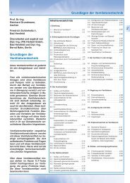
Centrifugal <strong>Fan</strong><br />
Seite 2<br />
in 1925 ►<br />
© <strong>TLT</strong>-<strong>Turbo</strong> <strong>GmbH</strong><br />
a Siemens Company
<strong>TLT</strong>-<strong>Turbo</strong> <strong>GmbH</strong> History<br />
Oberhausen<br />
Zweibrücken<br />
Bad Hersfeld<br />
KK&K<br />
Frankenthal<br />
Seite 3<br />
First centrifugal fan<br />
for power plants<br />
First axial action fan<br />
for power plants<br />
Foundation of Dingler Werke<br />
First centrifugal fan<br />
First large axial fans<br />
First Wind Tunnel<br />
First Tunnel Ventilation<br />
Foundation of Benno Schilde<br />
Maschinenwerke<br />
Foundation of <strong>Turbo</strong> Lufttechnik<br />
First centrifugal fan is built<br />
by Benno Schilde<br />
Foundation of Serial Factory<br />
Takeover of TURMAG<br />
AG KK&K<br />
Merger with<br />
All european fan manufacturing companies<br />
was founded<br />
Büttner-Schilde-Haas AG<br />
belonging to Babcock Borsig merge with <strong>TLT</strong><br />
Takeover of TROMAG<br />
First<br />
Takeover of KK&K fan devision<br />
centrifugal fan<br />
Takeover of TURBON<br />
Takeover of <strong>TLT</strong> Babcock<br />
KK&K Frankenthal Takeover,<br />
First axial fans<br />
<strong>TLT</strong>-<strong>Turbo</strong> <strong>GmbH</strong> founded<br />
of „Schicht“ type series AN<br />
Foundation of <strong>Turbo</strong>Group<br />
Axial fans with variable<br />
pitch blades<br />
Siemens PGI<br />
takes over KK&K<br />
and <strong>TLT</strong>-<strong>Turbo</strong> <strong>GmbH</strong><br />
The New York Blower<br />
takes over <strong>TLT</strong>-Babcock Inc.<br />
1827 1873 1932 1936 1963 1970 1981 1992 1995 1996<br />
1874<br />
1925<br />
1951<br />
1878 1966 1970 1972 1973<br />
1899<br />
1900<br />
1936<br />
1960<br />
2001<br />
2003<br />
2003<br />
2005<br />
2006<br />
© <strong>TLT</strong>-<strong>Turbo</strong> <strong>GmbH</strong><br />
a Siemens Company
<strong>TLT</strong>-<strong>Turbo</strong> <strong>GmbH</strong> History<br />
Seite 4<br />
Industrial <strong>Fan</strong>s<br />
System<br />
KK&K-Frankenthal<br />
Industrial <strong>Fan</strong>s<br />
System Babcock Bad Hersfeld<br />
<strong>TLT</strong>-<strong>Turbo</strong> <strong>GmbH</strong><br />
Industrial <strong>Fan</strong>s<br />
System Babcock<br />
Oberhausen<br />
© <strong>TLT</strong>-<strong>Turbo</strong> <strong>GmbH</strong><br />
a Siemens Company
Locations of <strong>TLT</strong>-<strong>Turbo</strong> <strong>GmbH</strong> in Germany<br />
Seite 5<br />
Oberhausen Zweibrücken Frankenthal Bad Hersfeld<br />
© <strong>TLT</strong>-<strong>Turbo</strong> <strong>GmbH</strong><br />
a Siemens Company
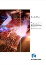
Solutions for Each Type of Application<br />
▲ power plants<br />
Seite 6<br />
mining ▼<br />
▲ steel industry<br />
technical building ▼<br />
equipment<br />
▲ (petro)chemical<br />
industry<br />
tunnel systems ▼<br />
metro<br />
▲ cement industry<br />
automobile and ▼<br />
aircraft industry<br />
© <strong>TLT</strong>-<strong>Turbo</strong> <strong>GmbH</strong><br />
a Siemens Company
BU Industrial <strong>Fan</strong>s<br />
Centrifugal <strong>Fan</strong>s<br />
installed world-wide: 7,500<br />
impeller diameter: up to 5,500 mm<br />
power consumption: 8,000 kW<br />
Seite 7<br />
Axial Impulse <strong>Fan</strong>s<br />
installed world-wide: 200<br />
impeller diameter: up to 4,220 mm<br />
power consumption: up to 5,500 kW<br />
© <strong>TLT</strong>-<strong>Turbo</strong> <strong>GmbH</strong><br />
a Siemens Company
Application Range of Compressor Types and<br />
<strong>Fan</strong> Applications<br />
discharge pressure [bar]<br />
Seite 8<br />
3.500<br />
1.000<br />
600<br />
250<br />
100<br />
10<br />
1,5<br />
100<br />
Reciprocating<br />
<strong>Turbo</strong> radial<br />
Screw / Rotary vane / Roots<br />
1.000 10.000<br />
100.000<br />
20.000 70.000 200.000 1.000.000<br />
actual suction volume [m 3 /h]<br />
<strong>Turbo</strong><br />
axial-(radial)<br />
<strong>Fan</strong> applications<br />
3.500.000<br />
© <strong>TLT</strong>-<strong>Turbo</strong> <strong>GmbH</strong><br />
a Siemens Company
Operating Ranges of Various <strong>Fan</strong> Types<br />
Seite 9<br />
specific energy Y in J / KG<br />
100000<br />
50000<br />
40000<br />
20000<br />
10000<br />
5000<br />
1000<br />
500<br />
200<br />
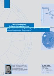
Centrifugal <strong>Fan</strong>s Tailor-Made<br />
Tailor Made<br />
Centrifugal <strong>Fan</strong>s Standard<br />
2<br />
5<br />
10<br />
20<br />
50<br />
100<br />
volume flow V in m3 .<br />
/s<br />
Axial Impulse <strong>Fan</strong>s<br />
200<br />
500<br />
1000<br />
2000<br />
© <strong>TLT</strong>-<strong>Turbo</strong> <strong>GmbH</strong><br />
a Siemens Company
Characteristics of Various Impellers<br />
Seite 10<br />
ratio impeller diameter<br />
u<br />
efficiency<br />
ratio of volume flow and pressure increase<br />
ηηηη<br />
δδδδ<br />
© <strong>TLT</strong>-<strong>Turbo</strong> <strong>GmbH</strong><br />
a Siemens Company
Standard <strong>Fan</strong>s<br />
Seite 11<br />
Type RUM (REM) Type RUR (RER/RSR) Type RUK (REK/RSK)<br />
Type RUK (REK/RSK) Type RUR (RER/RSR) Type RUK (RSK)<br />
Standard <strong>Fan</strong>s<br />
Single Suction <strong>Fan</strong>s.<br />
Impeller overhung or between<br />
bearings.<br />
With standard accessories.<br />
Based on a modular<br />
construction system.<br />
© <strong>TLT</strong>-<strong>Turbo</strong> <strong>GmbH</strong><br />
a Siemens Company
Standard <strong>Fan</strong>s<br />
Seite 12<br />
Type ZEK Type ZSK Type ZEK<br />
Type ZSK<br />
Type ZER Type ZSR Type ZER Type ZSR<br />
Standard <strong>Fan</strong>s<br />
Double Suction <strong>Fan</strong>s.<br />
With standard accessories.<br />
Based on a modular<br />
construction system.<br />
© <strong>TLT</strong>-<strong>Turbo</strong> <strong>GmbH</strong><br />
a Siemens Company
Standard <strong>Fan</strong>s<br />
<strong>Fan</strong> Types and Type Designation for Standard <strong>Fan</strong>s<br />
Seite 13<br />
nominal size - inlet diameter of the fan casing<br />
nomination I - without common base frame<br />
II - with common base frame for installation with vibration dampers<br />
III - for installation on concrete foundation<br />
IV - for installation on concrete foundation with common base frame<br />
V - for installation on concrete foundation with common base frame<br />
and impeller located between bearings<br />
configuration R - single inlet<br />
Z - double inlet<br />
U - directly connected to the piping<br />
E - free suction via suction nozzle<br />
S - with suction box<br />
M - impeller directly connected with the motor shaft<br />
K - with coupling<br />
R - with belts and pulleys<br />
series 14 - ratio of impeller inlet diameter to impeller outlet diameter<br />
45 - outlet angle of the impeller blade<br />
© <strong>TLT</strong>-<strong>Turbo</strong> <strong>GmbH</strong><br />
a Siemens Company
Tailor-Made <strong>Fan</strong>s<br />
Seite 14<br />
assigned casings gradation of impeller shapes gradation of size<br />
gradation of casing shapes<br />
Continuously adjustable casing shape in accordance with the outside diameter.<br />
Optimally designed operating points for highest<br />
efficiency and economy.<br />
© <strong>TLT</strong>-<strong>Turbo</strong> <strong>GmbH</strong><br />
a Siemens Company
Tailor-Made <strong>Fan</strong>s<br />
Seite 15<br />
Single Inlet Centrifugal <strong>Fan</strong><br />
Supported on one side of impeller (overhung<br />
design).<br />
Single Inlet Centrifugal <strong>Fan</strong><br />
Supported on both sides of impeller (simply<br />
supported).<br />
Individual fan design & manufacturing in accordance with customer specifications.<br />
© <strong>TLT</strong>-<strong>Turbo</strong> <strong>GmbH</strong><br />
a Siemens Company
Tailor-Made <strong>Fan</strong>s<br />
Seite 16<br />
Double Inlet Centrifugal <strong>Fan</strong><br />
Supported on both sides of impeller.<br />
Axial Impulse <strong>Fan</strong><br />
I.D. <strong>Fan</strong> arranged as horizontal axial impulse<br />
fan with inlet vane control.<br />
Individual fan design & manufacturing in accordance with customer specifications.<br />
© <strong>TLT</strong>-<strong>Turbo</strong> <strong>GmbH</strong><br />
a Siemens Company
Tailor-Made <strong>Fan</strong>s<br />
<strong>Fan</strong> Types and Type Designation for Tailor-Made <strong>Fan</strong>s<br />
Seite 17<br />
inlet diameter of the impeller<br />
configuration B - impeller located between bearing<br />
Z - double suction fan<br />
M - double stage fan<br />
_ A - revised version<br />
series impeller type<br />
relation inlet to ratio of impeller inlet diameter and impeller outlet diameter<br />
outlet diameter multiplied by 100<br />
© <strong>TLT</strong>-<strong>Turbo</strong> <strong>GmbH</strong><br />
a Siemens Company
Different Blade Designs<br />
For Impellers with Single Thickness Blades<br />
straight blades<br />
application for<br />
adhesive dust<br />
inlet angle: 60 °<br />
outlet angle: 78 °<br />
Seite 18<br />
backward-curved<br />
blades<br />
high pressure at high<br />
efficiency<br />
inlet angle: 35 °<br />
outlet angle: 40-45 °<br />
backward-curved<br />
blades<br />
for dust application<br />
which optimizes<br />
efficiency and<br />
minimizes build-up<br />
inlet angle: 45 °<br />
outlet angle: 45 °<br />
forward-curved<br />
inclined blades<br />
for wet dust<br />
inlet angle: 40 °<br />
outlet angle: 90 °<br />
© <strong>TLT</strong>-<strong>Turbo</strong> <strong>GmbH</strong><br />
a Siemens Company
Impeller with Aerofoiled Blades<br />
aerofoiled blades for high efficiency (90 %)<br />
volume flow up to 800 m 3 /s<br />
pressure increase up to 15,000 Pa<br />
shaft power up to 8,000 kW<br />
Seite 19<br />
reinforced on the inside for high strength<br />
© <strong>TLT</strong>-<strong>Turbo</strong> <strong>GmbH</strong><br />
a Siemens Company
Coke Dry Quenching System<br />
Recirculation <strong>Fan</strong>s<br />
Double Suction <strong>Fan</strong>.<br />
Impeller is mounted between<br />
bearings.<br />
With sleeve bearings. ▼<br />
Seite 20<br />
coke<br />
battery<br />
crane<br />
coke hoppit<br />
exhaustion<br />
trolley<br />
cooling chamber<br />
suction hood<br />
ante<br />
chamber<br />
discharge<br />
pre-separator<br />
heat recovery<br />
boiler<br />
tube cooler<br />
baghouse filter<br />
water<br />
steam<br />
coke gas recirculation fan<br />
© <strong>TLT</strong>-<strong>Turbo</strong> <strong>GmbH</strong><br />
a Siemens Company<br />
fan<br />
cyclone
Coke Dry Quenching System<br />
Recirculation <strong>Fan</strong>s<br />
Coke Gas Recirculation <strong>Fan</strong><br />
Special Features<br />
Designed as centrifugal fans with wear protection on impeller and housing to protect<br />
the fan against the abrasive coke dust.<br />
Operation behind cyclone.<br />
Mostly double width, double inlet design, with impeller supported on both sides on an<br />
elevated concrete foundation.<br />
These fans are controlled by speed and additionally by inlet damper.<br />
Seite 21<br />
© <strong>TLT</strong>-<strong>Turbo</strong> <strong>GmbH</strong><br />
a Siemens Company
Coke Dry Quenching System<br />
Recirculation <strong>Fan</strong>s<br />
Coke Gas Recirculation <strong>Fan</strong><br />
Typical Data<br />
Seite 22<br />
volume flow: 50-150 m 3 /s<br />
temperature: about 175 °C<br />
mech. design temperature: 250 °C<br />
static pressure increase: approx. 10,000 – 14,000 Pa<br />
© <strong>TLT</strong>-<strong>Turbo</strong> <strong>GmbH</strong><br />
a Siemens Company
Converter with Wet Cleaning Application<br />
fresh air<br />
Seite 23<br />
converter<br />
scrubber<br />
converter waste<br />
gas fan<br />
flare<br />
gasholder<br />
Converter Waste Gas <strong>Fan</strong><br />
executed as a centrifugal fan<br />
© <strong>TLT</strong>-<strong>Turbo</strong> <strong>GmbH</strong><br />
a Siemens Company
Converter with Wet Cleaning Application<br />
Waste Gas <strong>Fan</strong><br />
Special Features<br />
Dust loaded with 1 g/m 3 (build-up and wearing).<br />
Operation behind converter.<br />
Gastight application, 52-66 % CO gas.<br />
Blade and main disc of the impeller are equipped with wear protection (compound<br />
wear plates with hard-surfacing; chromium carbide with HRC 60).<br />
Spiral of casing with additional wear protection made from Hardox 400.<br />
Water injection device; 2 nozzles for the blades, 1 nozzle for the cover disc, 1 nozzle<br />
for the main disc.<br />
Rotor designed for 35,000 load-cycle changes.<br />
<strong>Fan</strong> control: speed control via inverter or hydraulic coupling.<br />
Seite 24<br />
© <strong>TLT</strong>-<strong>Turbo</strong> <strong>GmbH</strong><br />
a Siemens Company
Converter with Wet Cleaning Application<br />
Waste Gas <strong>Fan</strong><br />
Typical Data<br />
Seite 25<br />
volume flow: 50-60 m 3 /s<br />
temperature: 60-70 °C<br />
mech. design temperature: 120 °C<br />
pressure increase: 20,000 – 28,000 Pa<br />
shaft power: up to 2,200 kW<br />
maximum speed: 1,500 rpm<br />
© <strong>TLT</strong>-<strong>Turbo</strong> <strong>GmbH</strong><br />
a Siemens Company
Converter with Dry Cleaning Application<br />
Seite 26<br />
fresh air<br />
pre-separator<br />
converter<br />
heat recovery<br />
boiler<br />
Converter Waste Gas <strong>Fan</strong><br />
steam<br />
water<br />
electrical precipitator converter waste<br />
gas fan<br />
flare<br />
executed as an axial impulse fan<br />
© <strong>TLT</strong>-<strong>Turbo</strong> <strong>GmbH</strong><br />
a Siemens Company<br />
gasholder
Converter with Dry Cleaning Application<br />
Waste Gas <strong>Fan</strong><br />
Special Features<br />
Designed as axial impulse fans because of possible explosions or pressure shocks in<br />
the plant; circular housing and an axial flow direction across the impeller are safer as<br />
with a centrifugal fan.<br />
Higher tightness of an axial fan against the ambient area because of toxic parts in the<br />
gas composition.<br />
Static pressure increase is executed by a diffuser, not by impeller.<br />
Seite 27<br />
© <strong>TLT</strong>-<strong>Turbo</strong> <strong>GmbH</strong><br />
a Siemens Company
Converter with Dry Cleaning Application<br />
Waste Gas <strong>Fan</strong><br />
Typical Data<br />
Seite 28<br />
volume flow: 30-170 m 3 /s<br />
temperature: about 150 °C<br />
mech. design temperature: 250 °C<br />
static pressure increase: 6,000 – 9,000 Pa<br />
© <strong>TLT</strong>-<strong>Turbo</strong> <strong>GmbH</strong><br />
a Siemens Company
Axial Impulse <strong>Fan</strong><br />
Seite 29<br />
© <strong>TLT</strong>-<strong>Turbo</strong> <strong>GmbH</strong><br />
a Siemens Company
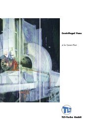
Axial Impulse <strong>Fan</strong><br />
Seite 30<br />
electric drive motor<br />
suction box<br />
performance characteristic<br />
stabilisation<br />
actuator<br />
inlet guide vane<br />
impeller<br />
cooling air for the<br />
bearing<br />
guide vanes<br />
downstream<br />
diffuser<br />
© <strong>TLT</strong>-<strong>Turbo</strong> <strong>GmbH</strong><br />
a Siemens Company
Axial Impulse <strong>Fan</strong><br />
Seite 31<br />
© <strong>TLT</strong>-<strong>Turbo</strong> <strong>GmbH</strong><br />
a Siemens Company
Pelletizing Plant<br />
Seite 32<br />
CAF – Cooling Air <strong>Fan</strong><br />
Designed for high volume flows and ambient<br />
temperature.<br />
Double inlet centrifugal fan with aerofoil<br />
blades.<br />
An axial flow fan would also be possible.<br />
UDF – Updraught Drying <strong>Fan</strong><br />
Draws process gas (250-400 °C) from the<br />
hood above the second cooling zone into the<br />
updraught drying zone.<br />
Protected by hard-surfaced liners.<br />
WRF – Windbox Recuperation <strong>Fan</strong><br />
Handles hot process gas (300-400 °C).<br />
Protected by hard-surfaced liners.<br />
© <strong>TLT</strong>-<strong>Turbo</strong> <strong>GmbH</strong><br />
a Siemens Company
Pelletizing Plant<br />
Seite 33<br />
WEF – Windbox Exhaust <strong>Fan</strong><br />
Installed behind filter with lower dust content<br />
(ca. 100 mg/m 3 ).<br />
Temperature: 50-300 °C.<br />
Double inlet fans with backward-curved<br />
blades.<br />
Protected by hard-surfaced liners.<br />
HEF – Hood Exhaust <strong>Fan</strong><br />
Similar design features as the windbox<br />
exhaust fans.<br />
Protected by hard-surfaced liners.<br />
An axial flow fan would also be possible (only<br />
without wear protection).<br />
© <strong>TLT</strong>-<strong>Turbo</strong> <strong>GmbH</strong><br />
a Siemens Company
Pelletizing Plant<br />
Seite 34<br />
impeller diameter: 4,500 mm<br />
rotor weight: 13,000 kg<br />
shaft power: 3,150 kW<br />
speed: 890 rpm<br />
temperature: 470 °C<br />
Impeller material: S890QL, S960QL with corresponding material tests.<br />
Centre disc with liners and scalloped design.<br />
Blades with hard-surfaced liners (welded or bolted).<br />
© <strong>TLT</strong>-<strong>Turbo</strong> <strong>GmbH</strong><br />
a Siemens Company
Pelletizing Plant<br />
Windbox Recuperator <strong>Fan</strong>, year of delivery: 2005.<br />
Seite 35<br />
© <strong>TLT</strong>-<strong>Turbo</strong> <strong>GmbH</strong><br />
a Siemens Company
Sinter Plant<br />
Sinter Waste Gas <strong>Fan</strong><br />
Seite 36<br />
stack<br />
fan<br />
ready-mix silo<br />
electrical precipitator<br />
Draws the process gas (120-200 °C) through the sinter machine and electrical<br />
precipitator to the stack.<br />
The gas contains highly abrasive dust (ca. 100-200 mg/m 3 ).<br />
The double suction impeller is equipped with wear protection in form of hardsurfacing.<br />
air<br />
gas, oil<br />
ignition kiln<br />
sinter machine<br />
crusher<br />
exhaust pipe<br />
© <strong>TLT</strong>-<strong>Turbo</strong> <strong>GmbH</strong><br />
a Siemens Company
Sinter Plant<br />
Seite 37<br />
Centrifugal <strong>Fan</strong><br />
double inlet<br />
impeller between bearings<br />
regulation by inlet damper<br />
shaft with sleeve bearings<br />
oil supply unit<br />
© <strong>TLT</strong>-<strong>Turbo</strong> <strong>GmbH</strong><br />
a Siemens Company
Cement Plant<br />
Main process gas fans in the cement<br />
industry<br />
Raw-Mill <strong>Fan</strong>s<br />
Compound <strong>Fan</strong>s<br />
Kiln Exhaust <strong>Fan</strong>s<br />
Clinker Cooler Exhaust <strong>Fan</strong>s<br />
Coal Mill <strong>Fan</strong>s<br />
Electrical Precipitator <strong>Fan</strong>s<br />
Usually the production rate of a cement plant<br />
adds up to 1,000-10,000 tons per day.<br />
Seite 38<br />
© <strong>TLT</strong>-<strong>Turbo</strong> <strong>GmbH</strong><br />
a Siemens Company
Cement Plant<br />
Raw-Mill <strong>Fan</strong><br />
Typical Data<br />
Seite 39<br />
volume flow: 80-350 m 3 /s<br />
temperature: 90-100 °C<br />
mech. design temperature: 250 °C<br />
pressure increase: 7,000 – 10,000 Pa<br />
shaft power: up to 4,500 kW<br />
maximum speed: 1,000 rpm (50 Hz)<br />
900 rpm (60 Hz)<br />
© <strong>TLT</strong>-<strong>Turbo</strong> <strong>GmbH</strong><br />
a Siemens Company
Cement Plant<br />
Raw-Mill <strong>Fan</strong><br />
Special Features<br />
Dust loaded with 30-50 g/m 3 (wearing).<br />
Operation behind cyclone.<br />
impeller and main disc are equipped with wear protection (compound wear plates).<br />
Spiral of casing with additional wear protection made from St 52 (NAXTRA).<br />
<strong>Fan</strong> control: in the majority of cases with damper flaps on the suction boxes.<br />
Seite 40<br />
© <strong>TLT</strong>-<strong>Turbo</strong> <strong>GmbH</strong><br />
a Siemens Company
Cement Plant<br />
Compound <strong>Fan</strong><br />
Typical Data<br />
Seite 41<br />
volume flow: 100-450 m 3 /s<br />
temperature: ca. 150 °C<br />
mech. design temperature: 200 °C<br />
pressure increase: 2,500 – 3,500 Pa<br />
maximum speed: 1,000 rpm (50 Hz)<br />
900 rpm (60 Hz)<br />
© <strong>TLT</strong>-<strong>Turbo</strong> <strong>GmbH</strong><br />
a Siemens Company
Cement Plant<br />
Compound <strong>Fan</strong><br />
Special Features<br />
Often equipped with aerofoiled blades.<br />
<strong>Fan</strong> control: in the majority of cases the speed control is performed by frequency<br />
converters.<br />
Sometimes the speed is less than mentioned before (600-750 rpm instead of<br />
1,000 rpm), conditioned by high amounts and low pressure at the same time.<br />
Broad blades, low-speed motor.<br />
Seite 42<br />
© <strong>TLT</strong>-<strong>Turbo</strong> <strong>GmbH</strong><br />
a Siemens Company
Cement Plant<br />
Kiln Exhaust <strong>Fan</strong><br />
Typical Data<br />
Seite 43<br />
volume flow: 70-180 m 3 /s<br />
temperature: 280-430 °C<br />
mech. design temperature: 450 °C (steady-state performance)<br />
500 °C (for a short time in event of fault)<br />
pressure increase: 7,000 – 10,000 Pa<br />
(exception: 13,000 Pa)<br />
maximum speed: 1,000 rpm (50 Hz) or<br />
1,200 rpm (60 Hz)<br />
© <strong>TLT</strong>-<strong>Turbo</strong> <strong>GmbH</strong><br />
a Siemens Company
Cement Plant<br />
Kiln Exhaust <strong>Fan</strong><br />
Special Features<br />
Dust loaded with 30 g/m 3 (strong build-up).<br />
Use of a special blade shape to extend the period between maintenance outages.<br />
Use of an air blower unit (compressed air onto the blades).<br />
<strong>Fan</strong> control: speed control by frequency converter.<br />
Sometimes equipped with coasting drive.<br />
At high volume flows two fans are run at the same time.<br />
Seite 44<br />
© <strong>TLT</strong>-<strong>Turbo</strong> <strong>GmbH</strong><br />
a Siemens Company
Cement Plant<br />
Clinker Cooler Exhaust <strong>Fan</strong><br />
Typical Data<br />
Seite 45<br />
volume flow: 100-350 m 3 /s<br />
temperature: 200-430 °C<br />
mech. design temperature: 450 °C (steady-state performance)<br />
pressure increase: 2,000 – 3,500 Pa<br />
maximum speed: 1,000 rpm (50 Hz)<br />
900 rpm (60 Hz)<br />
© <strong>TLT</strong>-<strong>Turbo</strong> <strong>GmbH</strong><br />
a Siemens Company
Cement Plant<br />
Clinker Cooler Exhaust <strong>Fan</strong><br />
Special Features<br />
Operation behind filter (therefore generally no wearing).<br />
Increased number of damages in case of filter failure or outages (therefore not<br />
equipped with profiled blades).<br />
Wear protection (as Raw-Mill <strong>Fan</strong>).<br />
<strong>Fan</strong> control: speed control by frequency converter.<br />
Sometimes the speed is less than mentioned before (750 rpm instead of<br />
1,000 rpm), conditioned by high amounts and low pressure at the same time.<br />
Seite 46<br />
© <strong>TLT</strong>-<strong>Turbo</strong> <strong>GmbH</strong><br />
a Siemens Company
Cement Plant<br />
Coal Mill <strong>Fan</strong><br />
Typical Data<br />
Seite 47<br />
volume flow: 20-60 m 3 /s<br />
temperature: ca. 100 °C<br />
mech. design temperature: 150 °C<br />
pressure increase: ca. 8,000 Pa<br />
maximum speed: 1,500 rpm (50 Hz)<br />
1,800 rpm (60 Hz)<br />
© <strong>TLT</strong>-<strong>Turbo</strong> <strong>GmbH</strong><br />
a Siemens Company
Cement Plant<br />
Coal Mill <strong>Fan</strong><br />
Special Features<br />
Often applications in dust-laden air (risk of explosive pressure shocks).<br />
Therefore casing and suction boxes are designed with a pressure shock resistance of<br />
1.4 bar (casing and suction boxes may deform but not break).<br />
<strong>Fan</strong> control: in the majority of cases with damper flaps on the suction boxes.<br />
Seite 48<br />
© <strong>TLT</strong>-<strong>Turbo</strong> <strong>GmbH</strong><br />
a Siemens Company
Power Plant<br />
<strong>Fan</strong>s For Power Plant and Air Pollution <strong>Control</strong> Applications<br />
Seite 49<br />
1<br />
2<br />
3<br />
2 3 4 5<br />
1<br />
1<br />
2<br />
3<br />
4<br />
5<br />
4<br />
5<br />
NO x -Air <strong>Fan</strong><br />
Sealing Air <strong>Fan</strong><br />
Primary Air <strong>Fan</strong><br />
Forced Draught <strong>Fan</strong><br />
Induced Draught <strong>Fan</strong><br />
© <strong>TLT</strong>-<strong>Turbo</strong> <strong>GmbH</strong><br />
a Siemens Company
Power Plant<br />
<strong>Fan</strong>s For Power Plant and Air Pollution <strong>Control</strong> Applications<br />
Configurations.<br />
Seite 50<br />
© <strong>TLT</strong>-<strong>Turbo</strong> <strong>GmbH</strong><br />
a Siemens Company
Power Plant<br />
——— Variable pitch blade Axial Flow <strong>Fan</strong> in horizontal position. ————————<br />
Seite 51<br />
© <strong>TLT</strong>-<strong>Turbo</strong> <strong>GmbH</strong><br />
a Siemens Company
Power Plant<br />
Seite 52<br />
diffuser<br />
expansion joint<br />
pressure side<br />
rotor<br />
intermediate<br />
shaft<br />
fan housing<br />
oil supply unit<br />
expansion joint<br />
suction side<br />
suction box<br />
cooling air fan<br />
drive motor<br />
spring damper<br />
foundation block<br />
——— Variable pitch blade Axial Flow <strong>Fan</strong> in horizontal position. ————————<br />
© <strong>TLT</strong>-<strong>Turbo</strong> <strong>GmbH</strong><br />
a Siemens Company
Power Plant<br />
Seite 53<br />
actuator<br />
motor cooling system<br />
oil supply unit<br />
shock absorbers<br />
drain pipe<br />
system<br />
confuser<br />
rubber lining (inside)<br />
sound insulation<br />
aerodyn. measuring taps<br />
vibration pick-up<br />
sealing air system<br />
fan housing<br />
built-in motor<br />
diffuser<br />
acid proof expansion<br />
joint<br />
Vertical FGD Axial Flow <strong>Fan</strong> with hub mounted drive motor.<br />
© <strong>TLT</strong>-<strong>Turbo</strong> <strong>GmbH</strong><br />
a Siemens Company
Power Plant<br />
Booster <strong>Fan</strong> in China<br />
gear box<br />
auxiliary<br />
drive<br />
bearing<br />
support<br />
floating<br />
bearing<br />
overrunning<br />
clutch<br />
Seite 54<br />
suction<br />
box<br />
flexible<br />
coupling<br />
hollow<br />
shaft<br />
housing<br />
impeller<br />
inlet vane<br />
control<br />
suction<br />
box<br />
fixed bearing<br />
flexible coupling<br />
with brake disc<br />
bearing<br />
support<br />
motor<br />
© <strong>TLT</strong>-<strong>Turbo</strong> <strong>GmbH</strong><br />
a Siemens Company
Power Plant<br />
Stainless Steel Application<br />
Seite 55<br />
Impeller for a Booster <strong>Fan</strong> for<br />
a power plant in Italy.<br />
<strong>Fan</strong> is installed behind a FGD<br />
plant (wet application).<br />
year of delivery: 2004<br />
impeller mat.: 1.4565<br />
(austenite)<br />
shaft power: 5,054 kW<br />
efficiency: 88.3 %<br />
blade design: aerofoiled<br />
© <strong>TLT</strong>-<strong>Turbo</strong> <strong>GmbH</strong><br />
a Siemens Company
Power Plant<br />
ID <strong>Fan</strong><br />
During balancing in the work shop.<br />
Seite 56<br />
volume flow: 518.9 m 3 /s<br />
pressure increase: 10,415 Pa<br />
temperature: 160 °C<br />
speed: 890 rpm<br />
shaft power: 5,792 kW<br />
efficiency: 90 %<br />
impeller diameter: 3,550 mm<br />
tip speed: 165 m/s<br />
control: inlet vane control<br />
year of delivery: 2002<br />
With scalloped main disc to reduce<br />
weight and moment of inertia.<br />
© <strong>TLT</strong>-<strong>Turbo</strong> <strong>GmbH</strong><br />
a Siemens Company
Seite 57<br />
Impeller of an ID <strong>Fan</strong> for a<br />
power plant<br />
impeller diameter: 3,550 mm<br />
impeller weight: 16,850 kg<br />
power requirement (shaft): 5,779 kW<br />
speed: 890 rpm<br />
temperature: 185 °C<br />
impeller material: P355NH, S690QL<br />
hollow shaft material: St 52-3<br />
© <strong>TLT</strong>-<strong>Turbo</strong> <strong>GmbH</strong><br />
a Siemens Company
Power Plant<br />
Booster <strong>Fan</strong><br />
volume flow: 755.1 m 3 /s<br />
pressure increase: 3,377 Pa<br />
temperature: 153 °C<br />
speed: 495 rpm<br />
efficiency: 88 %<br />
impeller diameter: 4,160 mm<br />
tip speed: 108 m/s<br />
control: inlet vane control<br />
year of delivery: 2000<br />
Inlet vane control located inside the<br />
housing to minimize the bearing<br />
distance.<br />
Seite 58<br />
© <strong>TLT</strong>-<strong>Turbo</strong> <strong>GmbH</strong><br />
a Siemens Company
Petrochemical Industry<br />
Seite 59<br />
Centrifugal <strong>Fan</strong><br />
With dual drive via<br />
turbine and motor.<br />
© <strong>TLT</strong>-<strong>Turbo</strong> <strong>GmbH</strong><br />
a Siemens Company
Petrochemical Industry<br />
Fresh Air <strong>Fan</strong><br />
volume flow: 68.61 m 3 /s turbine: 1,060 kW<br />
total pressure increase: 11,140 Pa speed: 1,500 rpm<br />
motor power rating: 1,120 kW<br />
Seite 60<br />
© <strong>TLT</strong>-<strong>Turbo</strong> <strong>GmbH</strong><br />
a Siemens Company
Petrochemical Industry<br />
Applications<br />
<strong>Fan</strong> Types<br />
FD <strong>Fan</strong>s (Combustion Air <strong>Fan</strong>s)<br />
ID <strong>Fan</strong>s (Flue Gas <strong>Fan</strong>s, Recirculation <strong>Fan</strong>s)<br />
Process Gas <strong>Fan</strong>s<br />
CO 2 -Gas <strong>Fan</strong>s<br />
Axial Flow <strong>Fan</strong>s<br />
Seite 61<br />
© <strong>TLT</strong>-<strong>Turbo</strong> <strong>GmbH</strong><br />
a Siemens Company
Petrochemical Industry<br />
Actual Applications<br />
Heater / Reformer Section:<br />
Combustion Air <strong>Fan</strong>s<br />
Flue Gas <strong>Fan</strong>s, Recirculation <strong>Fan</strong>s<br />
Urea / NH 3 (Fertilizer):<br />
Process Gas <strong>Fan</strong>s<br />
Gas Turbines / Heat Recovery Steam Generators (HRSG):<br />
FD <strong>Fan</strong>s for substitute firing<br />
ID <strong>Fan</strong>s behind HRSG<br />
Furnaces:<br />
Process applications<br />
Seite 62<br />
© <strong>TLT</strong>-<strong>Turbo</strong> <strong>GmbH</strong><br />
a Siemens Company
Petrochemical Industry<br />
Possible Applications<br />
Prilling Tower <strong>Fan</strong>s:<br />
Axial <strong>Fan</strong>s, stainless steel<br />
Platform Installations for Gas Regeneration:<br />
Package Units<br />
Chlorine Gas <strong>Fan</strong>s:<br />
high-alloy steel (up to 550 °C)<br />
Sealing Air / Seal Gas <strong>Fan</strong>s<br />
Seite 63<br />
© <strong>TLT</strong>-<strong>Turbo</strong> <strong>GmbH</strong><br />
a Siemens Company
Petrochemical Industry<br />
Design Details<br />
<strong>Fan</strong>s in Heater / Reformer Section<br />
Heating of process gases in heat exchangers by LNG firing, sometimes by<br />
residue firing. However, there is no contact between fan and process gas.<br />
LNG firing: clean flue gas.<br />
residue firing: possibly corrosive agents in the flue gas.<br />
As per API 560 / 673 –<br />
<strong>Fan</strong>s with turbine and / or motor drive, dual drive with coupling / clutches;<br />
shaft power up to 3.5 MW.<br />
Accessories:<br />
Air intake tower with filter, silencer, venturi, inlet guide vanes / dampers with<br />
pneumatic actuator, sleeve bearings with external oil lubrications system,<br />
instrumentation and controls as per API 670.<br />
Seite 64<br />
© <strong>TLT</strong>-<strong>Turbo</strong> <strong>GmbH</strong><br />
a Siemens Company
Petrochemical Industry<br />
Seite 65<br />
© <strong>TLT</strong>-<strong>Turbo</strong> <strong>GmbH</strong><br />
a Siemens Company
Petrochemical Industry<br />
Design Details<br />
<strong>Fan</strong>s in Urea / NH 3 Process<br />
Granulation Fluidisation <strong>Fan</strong><br />
Granulation Atomisation <strong>Fan</strong><br />
First Cooler Fluidisation <strong>Fan</strong><br />
Granulator Scrubber Exhaust <strong>Fan</strong><br />
Dedusting <strong>Fan</strong><br />
Final Cooler Fluidisation <strong>Fan</strong><br />
Fumes Extraction <strong>Fan</strong><br />
Seite 66<br />
© <strong>TLT</strong>-<strong>Turbo</strong> <strong>GmbH</strong><br />
a Siemens Company
Petrochemical Industry<br />
Seite 67<br />
© <strong>TLT</strong>-<strong>Turbo</strong> <strong>GmbH</strong><br />
a Siemens Company
Petrochemical Industry<br />
Design Details<br />
<strong>Fan</strong>s in Urea / NH 3 Process<br />
<strong>Fan</strong>s in contact with process gases and products, therefore partly made from<br />
stainless steels.<br />
<strong>Fan</strong>s as per API 560 / 673, mostly motor driven, turbines are possbile.<br />
Shaft power between 50 kW and 1,500 kW.<br />
Accessories depend on the location of the fan in the process.<br />
Sometimes connecting ducts and components as control dampers and supports<br />
with static calculation are included.<br />
Instrumentation and controls as per API 670.<br />
Seite 68<br />
© <strong>TLT</strong>-<strong>Turbo</strong> <strong>GmbH</strong><br />
a Siemens Company
Petrochemical Industry<br />
Design Details<br />
FD <strong>Fan</strong>s for substitute firing in HRSG<br />
<strong>Fan</strong>s as per API 560 / 673, mostly motor driven, turbines are possible.<br />
Shaft power between 50 kW and 500 kW.<br />
Accessories:<br />
Air intake tower with filter / sand trap, silencer, venturi tube, instrumentation,<br />
external oil lubrication system, etc.<br />
Accessories depend on the client and / or location.<br />
Sometimes connecting ducts and components as control dampers and supports<br />
with static calculation are included. Instrumentation and controls as per API 670.<br />
Seite 69<br />
© <strong>TLT</strong>-<strong>Turbo</strong> <strong>GmbH</strong><br />
a Siemens Company
Petrochemical Industry<br />
Standards, Guidelines<br />
API<br />
NEMA, OSHA, EEMUA, NFPA<br />
ASTM, ASME<br />
Company Standards (additions, supplements, substitutions to API)<br />
Seite 70<br />
SHELL DEP, Flour PMD, Sabic, BASF<br />
International <strong>Fan</strong> Specifications<br />
AWS<br />
© <strong>TLT</strong>-<strong>Turbo</strong> <strong>GmbH</strong><br />
a Siemens Company
Petrochemical Industry<br />
Seite 71<br />
© <strong>TLT</strong>-<strong>Turbo</strong> <strong>GmbH</strong><br />
a Siemens Company
Petrochemical Industry<br />
Seite 72<br />
© <strong>TLT</strong>-<strong>Turbo</strong> <strong>GmbH</strong><br />
a Siemens Company
Petrochemical Industry<br />
Seite 73<br />
© <strong>TLT</strong>-<strong>Turbo</strong> <strong>GmbH</strong><br />
a Siemens Company
Petrochemical Industry<br />
Seite 74<br />
© <strong>TLT</strong>-<strong>Turbo</strong> <strong>GmbH</strong><br />
a Siemens Company
Impeller with Scalloped Main Disc<br />
Seite 75<br />
Advantages<br />
weight of the impeller is reduced<br />
moment of inertia of the rotor is reduced<br />
less wearing on scalloped main disc<br />
more space to handle the changeable wear plates<br />
© <strong>TLT</strong>-<strong>Turbo</strong> <strong>GmbH</strong><br />
a Siemens Company
Impeller with Scalloped Main Disc<br />
——— Manufacturing of the main disc in the workshop. ————————————<br />
Seite 76<br />
© <strong>TLT</strong>-<strong>Turbo</strong> <strong>GmbH</strong><br />
a Siemens Company
Manufacturing of the Impeller<br />
——— Fixing the blades on the main disc. ——————————————————<br />
Seite 77<br />
© <strong>TLT</strong>-<strong>Turbo</strong> <strong>GmbH</strong><br />
a Siemens Company
Impeller Flange Connection<br />
Seite 78<br />
© <strong>TLT</strong>-<strong>Turbo</strong> <strong>GmbH</strong><br />
a Siemens Company
Hollow Shaft<br />
Reducing the weight of the shaft.<br />
Seite 79<br />
shaft end is<br />
shrinked to the tube welded after<br />
shrinking<br />
flange is welded on<br />
the shaft<br />
Creates sufficient space to the critical speed (at least 30 %).<br />
© <strong>TLT</strong>-<strong>Turbo</strong> <strong>GmbH</strong><br />
a Siemens Company
Hollow Shaft<br />
Seite 80<br />
Hollow Shaft<br />
During the shrinking process in<br />
the workshop.<br />
The shaft extension joint is<br />
cooled down to -170 °C with<br />
N 2 gas.<br />
The tube is going to be<br />
preheated up to 80 °C.<br />
© <strong>TLT</strong>-<strong>Turbo</strong> <strong>GmbH</strong><br />
a Siemens Company
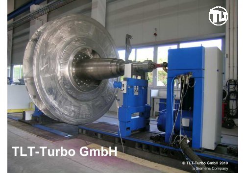
Balancing Machine<br />
maximal impeller diameter: 4,500 mm<br />
maximal impeller weight: 20 tons<br />
maximal length of the shaft: 7,000 mm<br />
Seite 81<br />
© <strong>TLT</strong>-<strong>Turbo</strong> <strong>GmbH</strong><br />
a Siemens Company
Performance Tests<br />
Performance test for a F.D. <strong>Fan</strong> in the <strong>TLT</strong><br />
workshop with reduced speed, driven by diesel<br />
engine.<br />
Seite 82<br />
volume flow: 304.3 m 3 /s<br />
pressure increase: 4,454 Pa<br />
temperature: 40 °C<br />
shaft power: 1,509 kW<br />
efficiency: 88.1 %<br />
control: combined hydraulic<br />
coupling, inlet vane<br />
control<br />
year of delivery: 1996<br />
© <strong>TLT</strong>-<strong>Turbo</strong> <strong>GmbH</strong><br />
a Siemens Company
Sleeve Bearing with Oil Ring<br />
Sleeve bearings as used in most of modern conceptions with many variations of the<br />
unit composed system.<br />
With natural cooling, water cooling in oil sump or cooling by circulated oil.<br />
Seite 83<br />
© <strong>TLT</strong>-<strong>Turbo</strong> <strong>GmbH</strong><br />
a Siemens Company
Sleeve Bearing with Hydrostatic Jacking<br />
Designed with Two Lubrication Pockets<br />
for applications with high start-up load, frequent operation at low speed and very<br />
long rundown periods to avoid wearing on the bearing shell<br />
The high pressure pumps for hydrostatic lifting units are constant volume systems, i.e. they<br />
supply a defined oil throughput. The maximum load carrying capacity of the system is<br />
usually limited to 200 bar.<br />
The maximum pump pressure occurs during the starting process, due to the oil wedge<br />
being narrow when the bearing is still at rest. The beginning of the shaft lifting thus involves<br />
a remarkable pressure surge. As soon as the oil wedge gets wider as the shaft is further<br />
lifted, the pressure decreases depending on the bearing geometry and the oil throughput,<br />
since the effectively load carrying surface is increased.<br />
The constant pump pressure for holding up the shaft should be adjusted to 100 bar.<br />
Seite 84<br />
© <strong>TLT</strong>-<strong>Turbo</strong> <strong>GmbH</strong><br />
a Siemens Company
Seite 85<br />
Wear Protection<br />
Blades are designed as aerofoiled<br />
blades.<br />
As the customer requested, the profile<br />
blades are equipped with a light wear<br />
protection in form of welded steel plates.<br />
© <strong>TLT</strong>-<strong>Turbo</strong> <strong>GmbH</strong><br />
a Siemens Company
Wear Protection<br />
wear protection on<br />
the blade inlet<br />
Unchangeable (welded )wear protection in form of hard-surfacing on the leading face of the blades and for the main plate.<br />
Hardness of the wear protection: at least HRC 60. Repair of the wear protection: with welding electrodes.<br />
Seite 86<br />
hard-surfacing on<br />
100 % of the blade<br />
cover disc<br />
hard-surfacing on<br />
the main disc<br />
© <strong>TLT</strong>-<strong>Turbo</strong> <strong>GmbH</strong><br />
a Siemens Company
Wear Protection<br />
Seite 87<br />
wear liner, bolted<br />
on the main disc<br />
chromium carbide on<br />
100% of the blade<br />
Changeable wear protection in form of hard-surfacing on 100% of the blade.<br />
blade material with<br />
high yield stress value<br />
main disc<br />
wear protection on<br />
the main plate<br />
base material for the<br />
wear protection<br />
© <strong>TLT</strong>-<strong>Turbo</strong> <strong>GmbH</strong><br />
a Siemens Company
Resistance Against Wearing<br />
Seite 88<br />
life time<br />
Hardness [HRC]<br />
70<br />
60<br />
50<br />
40<br />
30<br />
20<br />
10<br />
0<br />
NAXTRA ABRAZO 400<br />
Hardox 400<br />
Chromkarbid Chromium Carbide Steel<br />
Steel<br />
© <strong>TLT</strong>-<strong>Turbo</strong> <strong>GmbH</strong><br />
a Siemens Company
Wear Protection<br />
New modern wear protection made from chromium carbide.<br />
Seite 89<br />
© <strong>TLT</strong>-<strong>Turbo</strong> <strong>GmbH</strong><br />
a Siemens Company
Wear Protection<br />
Seite 90<br />
Changeable, hard-surfaced, parted<br />
wear protection (xuperwave method).<br />
© <strong>TLT</strong>-<strong>Turbo</strong> <strong>GmbH</strong><br />
a Siemens Company
Wear Protection<br />
Seite 91<br />
►<br />
►<br />
wear protection:<br />
hard-surfacing on<br />
100 % of the blades<br />
Typical cracks in the hard-surfacing layer<br />
because of the hardness of the material.<br />
© <strong>TLT</strong>-<strong>Turbo</strong> <strong>GmbH</strong><br />
a Siemens Company
Wear Protection<br />
protected inlet of the blade<br />
impeller for a converter fan<br />
impeller diameter: 2,778 mm<br />
volume flow: 119 m 3 /s<br />
pressure increase: 24,034 Pa<br />
temperature: 72 °C<br />
shaft power: 3,123 kW<br />
Seite 92<br />
▼<br />
© <strong>TLT</strong>-<strong>Turbo</strong> <strong>GmbH</strong><br />
a Siemens Company
Wood Chip Drying Application<br />
Seite 93<br />
<strong>Fan</strong>s for wood<br />
chip-, OSB- and<br />
MDF-dryers.<br />
© <strong>TLT</strong>-<strong>Turbo</strong> <strong>GmbH</strong><br />
a Siemens Company
Wood Chip Drying Application<br />
Seite 94<br />
OSB (oriented strand board)<br />
MDF (medium-density fibreboard)<br />
wood chips<br />
© <strong>TLT</strong>-<strong>Turbo</strong> <strong>GmbH</strong><br />
a Siemens Company
Wood Chip Drying Application<br />
OSB-Dryer<br />
hot gas<br />
generator<br />
Seite 95<br />
mixing<br />
chamber<br />
fan<br />
feeding<br />
device<br />
drying drum<br />
cyclone<br />
filter<br />
material outlet<br />
© <strong>TLT</strong>-<strong>Turbo</strong> <strong>GmbH</strong><br />
a Siemens Company
Wood Chip Drying Application<br />
MDF-Dryer<br />
Seite 96<br />
mixing<br />
chamber<br />
fan<br />
hot gas<br />
generator feeding<br />
device<br />
cyclone filter<br />
material outlet<br />
© <strong>TLT</strong>-<strong>Turbo</strong> <strong>GmbH</strong><br />
a Siemens Company
Wood Chip Drying Application<br />
MDF-Dryer<br />
Drying <strong>Fan</strong> 11/45 RUR III 2500<br />
volume flow: 713,000 m 3 /h<br />
pressure increase: 4,000 Pa<br />
temperature: 195 °C<br />
speed: 750 rpm<br />
shaft power: 2 x 630 kW<br />
Seite 97<br />
© <strong>TLT</strong>-<strong>Turbo</strong> <strong>GmbH</strong><br />
a Siemens Company
Wood Chip Drying Application<br />
MDF-Dryer<br />
Seite 98<br />
Drying <strong>Fan</strong> 1494 B/1972<br />
volume flow: 866,160 m 3 /h<br />
pressure increase: 7,412 Pa<br />
speed: 995 rpm<br />
shaft power: 2,300 kW<br />
© <strong>TLT</strong>-<strong>Turbo</strong> <strong>GmbH</strong><br />
a Siemens Company
Wood Chip Drying Application<br />
Wood Chip-Dryer<br />
Seite 99<br />
hot gas<br />
generator<br />
feeding<br />
device<br />
mixing<br />
chamber<br />
drying drum<br />
cyclone<br />
filter<br />
fan<br />
material outlet<br />
© <strong>TLT</strong>-<strong>Turbo</strong> <strong>GmbH</strong><br />
a Siemens Company
Wood Chip Drying Application<br />
Drying <strong>Fan</strong> 11/45 RUK III 2000<br />
volume flow: 490,000 m 3 /h speed: 980 rpm<br />
pressure increase: 4,600 Pa shaft power: 900 kW<br />
temperature: 125 °C<br />
Seite 100<br />
© <strong>TLT</strong>-<strong>Turbo</strong> <strong>GmbH</strong><br />
a Siemens Company
Wood Chip Drying Application<br />
New vane control (left), used vane control (right).<br />
Seite 101<br />
© <strong>TLT</strong>-<strong>Turbo</strong> <strong>GmbH</strong><br />
a Siemens Company
Wood Chip Drying Application<br />
Seite 102<br />
at low wood chip<br />
and dust loading<br />
backward-curved,<br />
e.g. type 14/45<br />
at high wood chip<br />
and dust loading<br />
straight blades,<br />
e.g. 14/60 St and 11/45.14<br />
at high dust loading<br />
forward-curved, radial tip,<br />
e.g. 11/60<br />
© <strong>TLT</strong>-<strong>Turbo</strong> <strong>GmbH</strong><br />
a Siemens Company
Research and Development Centres<br />
Zweibrücken and Bad Hersfeld<br />
We assure that all <strong>TLT</strong> products are continuously<br />
adapted to current local and international requirements.<br />
Our concept<br />
Application of the latest data processing programs<br />
to achieve the latest investigation and<br />
test methods in the <strong>TLT</strong> laboratories.<br />
Advanced measuring technique is also<br />
available for you at your local site.<br />
Continuous exchange of ideas with our<br />
customer.<br />
Intensive cooperation with well-known<br />
universities.<br />
Seite 103<br />
© <strong>TLT</strong>-<strong>Turbo</strong> <strong>GmbH</strong><br />
a Siemens Company
Subsupplier Stator Parts<br />
Seite 104<br />
►<br />
example:<br />
►<br />
manufacturing of<br />
stator company.<br />
DOKA/Turkey<br />
supplier of high quality<br />
since 20 years<br />
<strong>Fan</strong>-casing for a steel plant located in<br />
Ukraine.<br />
© <strong>TLT</strong>-<strong>Turbo</strong> <strong>GmbH</strong><br />
a Siemens Company
<strong>Fan</strong> <strong>Control</strong><br />
In principle, there are three possibilities to control a fan:<br />
<strong>Control</strong> by inlet vane control (IVC).<br />
<strong>Control</strong> by damper on the suction box.<br />
<strong>Control</strong> by speed.<br />
Seite 105<br />
© <strong>TLT</strong>-<strong>Turbo</strong> <strong>GmbH</strong><br />
a Siemens Company
<strong>Fan</strong> <strong>Control</strong><br />
<strong>Control</strong> by IVC (left), control by speed (right).<br />
Seite 106<br />
© <strong>TLT</strong>-<strong>Turbo</strong> <strong>GmbH</strong><br />
a Siemens Company
<strong>Fan</strong> <strong>Control</strong><br />
Seite 107<br />
© <strong>TLT</strong>-<strong>Turbo</strong> <strong>GmbH</strong><br />
a Siemens Company
<strong>Fan</strong> <strong>Control</strong><br />
Seite 108<br />
© <strong>TLT</strong>-<strong>Turbo</strong> <strong>GmbH</strong><br />
a Siemens Company
<strong>Fan</strong> <strong>Control</strong><br />
Seite 109<br />
© <strong>TLT</strong>-<strong>Turbo</strong> <strong>GmbH</strong><br />
a Siemens Company
<strong>Fan</strong> <strong>Control</strong><br />
<strong>Control</strong> by IVC (left), control by speed (right).<br />
Seite 110<br />
© <strong>TLT</strong>-<strong>Turbo</strong> <strong>GmbH</strong><br />
a Siemens Company
<strong>Fan</strong> <strong>Control</strong><br />
Seite 111<br />
The fan is always working<br />
on the point of intersection<br />
between fan performance<br />
curve and resistance-line<br />
of the plant.<br />
© <strong>TLT</strong>-<strong>Turbo</strong> <strong>GmbH</strong><br />
a Siemens Company
<strong>Fan</strong> <strong>Control</strong><br />
Seite 112<br />
In case of changing this<br />
resistance-line, the point of<br />
intersection also changes.<br />
As the fan performance curve<br />
is constant, this point moves on<br />
the fan performance curve.<br />
© <strong>TLT</strong>-<strong>Turbo</strong> <strong>GmbH</strong><br />
a Siemens Company
<strong>Fan</strong> <strong>Control</strong><br />
<strong>Control</strong> by IVC or damper<br />
Seite 113<br />
If the resistance-line is con-<br />
stant and the fan performance<br />
curve is changed by variation<br />
of the control device the point<br />
of intersection moves on the<br />
resistance-line.<br />
© <strong>TLT</strong>-<strong>Turbo</strong> <strong>GmbH</strong><br />
a Siemens Company
<strong>Fan</strong> <strong>Control</strong><br />
<strong>Control</strong> by Speed<br />
Seite 114<br />
The point of intersection also<br />
moves on the resistance-line<br />
in case of variation of the per-<br />
formance curve by speed va-<br />
riation (e.g. speed controlled<br />
motor).<br />
© <strong>TLT</strong>-<strong>Turbo</strong> <strong>GmbH</strong><br />
a Siemens Company
<strong>Fan</strong> <strong>Control</strong><br />
<strong>Control</strong> by IVC or damper<br />
Seite 115<br />
If the fan performance curve<br />
and the resistance-line are<br />
changed at the same time,<br />
the fan is still working in the<br />
point of intersection. So the<br />
point 1 “moves” accordingly.<br />
© <strong>TLT</strong>-<strong>Turbo</strong> <strong>GmbH</strong><br />
a Siemens Company
<strong>Fan</strong> <strong>Control</strong><br />
<strong>Control</strong> by speed<br />
Seite 116<br />
This is also valid in case of<br />
speed control.<br />
© <strong>TLT</strong>-<strong>Turbo</strong> <strong>GmbH</strong><br />
a Siemens Company
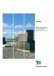
<strong>Fan</strong> <strong>Control</strong><br />
Seite 117<br />
14000<br />
J/kg<br />
12000<br />
10000<br />
8000<br />
6000<br />
4000<br />
2000<br />
0<br />
WAHR<br />
WAHR<br />
0 50 100 150 200 250 300 350 400<br />
Gebläsekennlinie<br />
Anlagenwiderstand (Auslegung)<br />
Arbeitspunkt<br />
aktueller Anlagenwiderstand<br />
aktuelle Gebläsekennlinie<br />
Wirkungsgrad Kennlinie<br />
Verlust im Gebläse<br />
Auslegungspunkt<br />
100%<br />
50%<br />
30%<br />
Anlagen Regler<br />
widerstand position<br />
© <strong>TLT</strong>-<strong>Turbo</strong> <strong>GmbH</strong><br />
a Siemens Company
<strong>Fan</strong> <strong>Control</strong><br />
<strong>Control</strong> by IVC (left), control by speed (right).<br />
Seite 118<br />
© <strong>TLT</strong>-<strong>Turbo</strong> <strong>GmbH</strong><br />
a Siemens Company
<strong>Fan</strong> <strong>Control</strong><br />
<strong>Control</strong> by IVC (left), control by speed (right).<br />
Seite 119<br />
© <strong>TLT</strong>-<strong>Turbo</strong> <strong>GmbH</strong><br />
a Siemens Company
<strong>Fan</strong> <strong>Control</strong><br />
Seite 120<br />
Power P w at shaft at MCR operation point<br />
IVC<br />
1,890 kW<br />
speed<br />
1,518 kW<br />
damper<br />
2,156 kW<br />
© <strong>TLT</strong>-<strong>Turbo</strong> <strong>GmbH</strong><br />
a Siemens Company
<strong>Fan</strong> <strong>Control</strong><br />
Seite 121<br />
Power P w at shaft at MCR operation point<br />
IVC speed damper<br />
P w = 1,890 1,518 2,156 kW<br />
Operation costs of an estimated operation time<br />
of 8,000 hours / year and costs of 0.10 € / kWh<br />
(electric power).<br />
IVC speed damper<br />
Costs = 1.512 1.214 1.725 m. €<br />
Diff. = 0 - 298 + 213 t. €<br />
© <strong>TLT</strong>-<strong>Turbo</strong> <strong>GmbH</strong><br />
a Siemens Company
Manufacturing of Industrial <strong>Fan</strong>s<br />
1. Factory Premises<br />
area: 4,500 m 2<br />
production hall: 2,900 m 2<br />
dimension: 63 m x 45 m<br />
crane<br />
hook height: up to 8.8 m<br />
lifting capacity: 2 x 25 t; 1 x 16 t<br />
Seite 122<br />
© <strong>TLT</strong>-<strong>Turbo</strong> <strong>GmbH</strong><br />
a Siemens Company
Manufacturing of Industrial <strong>Fan</strong>s<br />
2. Transport Connection<br />
railway<br />
Hamburg port: 360 km<br />
Frankfurt airport: 140 km<br />
federal motorway (A 4 and A 7): 3 km<br />
3. Internal Means of Transport<br />
mobile crane: 1,000 kg<br />
forklift: 3,500 kg<br />
Seite 123<br />
© <strong>TLT</strong>-<strong>Turbo</strong> <strong>GmbH</strong><br />
a Siemens Company
Manufacturing of Industrial <strong>Fan</strong>s<br />
4. Materials<br />
non-alloyed and alloyed quality steels, EN 10025-1<br />
non-alloyed stainless steels, EN 10025-2<br />
alloyed stainless steels, stable to chemicals,<br />
heat resistant , highly heat resisting, EN 10088-1<br />
fine-grained steels, EN 10025-6<br />
Seite 124<br />
© <strong>TLT</strong>-<strong>Turbo</strong> <strong>GmbH</strong><br />
a Siemens Company
Manufacturing of Industrial <strong>Fan</strong>s<br />
5. Welding Techniques<br />
according to DIN 1910 parts 2, 3, 4, 5<br />
6. Manufacturing and Testing Permissions<br />
according to DIN 18800 part 7<br />
according to DIN EN 287 and by following classification societies and<br />
regulations<br />
Technical Supervisory Association<br />
Seite 125<br />
© <strong>TLT</strong>-<strong>Turbo</strong> <strong>GmbH</strong><br />
a Siemens Company
Manufacturing of Industrial <strong>Fan</strong>s<br />
7. Method of Testing/Testing Facility<br />
Nondestructive Methods<br />
x-ray inspection (external service)<br />
ultrasonic checking<br />
crack detection (dye penetrant examination)<br />
crack detection (magnetic powder)<br />
leak tests<br />
hydraulic pressure tests<br />
surface roughness and layer thickness tests<br />
hardness tests<br />
Seite 126<br />
© <strong>TLT</strong>-<strong>Turbo</strong> <strong>GmbH</strong><br />
a Siemens Company
Manufacturing of Industrial <strong>Fan</strong>s<br />
7. Method of Testing/Testing Facility<br />
Destructive Methods<br />
folding tests<br />
Other Methods<br />
fan testing facility<br />
devices for ventilation measurement<br />
dust measurements<br />
immission measurements<br />
vibrometer<br />
sound-level meter<br />
Seite 127<br />
© <strong>TLT</strong>-<strong>Turbo</strong> <strong>GmbH</strong><br />
a Siemens Company
Manufacturing of Industrial <strong>Fan</strong>s<br />
8. Machinery<br />
Non-Machining Manufacturing<br />
round bending machine (max. plate width: 3,040 mm; max. plate thickness: 30 mm)<br />
Kraftformer (675/450 mm outreach, max. plate thickness: 8 mm)<br />
flange bending machine (3,600 mm Ø x 12 mm)<br />
three-roll plate bending machine (max. plate width: 2,500 mm; max. plate thickness:<br />
20 mm)<br />
Seite 128<br />
© <strong>TLT</strong>-<strong>Turbo</strong> <strong>GmbH</strong><br />
a Siemens Company
Manufacturing of Industrial <strong>Fan</strong>s<br />
8. Machinery<br />
Machining Manufacturing<br />
turning lathes (max. 1,050 mm turningØ at 3,000 mm turning length,<br />
max. 800 mm turning length at 900 mm turningØ)<br />
vertical lathe (max. 2,350 mm turningØ, max. 1,250 mm working height)<br />
radial drill machine (max. 60 mm drillØ)<br />
keyseating machine (max. 650 mm drawing length, max. 65 mm keyseat width)<br />
balancing machine 1 (max. 2,800 mm Ø, 4,300 mm length, 7,000 kg loading)<br />
balancing machine 2 (max. 4,500 mm Ø, 7,500 mm length, 20,000 kg loading)<br />
blasting plant (7,000 mm length, 5,000 mm width, 3,000 mm height)<br />
spray station (5,000 x 5,000 mm)<br />
Seite 129<br />
© <strong>TLT</strong>-<strong>Turbo</strong> <strong>GmbH</strong><br />
a Siemens Company
Manufacturing of Industrial <strong>Fan</strong>s<br />
9. Welding<br />
two rotary tables with 2,000 mm Ø<br />
one rotary table with 2,500 mm Ø<br />
one rotary table with 3,000 mm Ø<br />
one rotary table with 4,000 mm Ø<br />
one rotary table with 4,500 mm Ø<br />
15 welding machines (MAG)<br />
two plasma slicing machines<br />
Seite 130<br />
© <strong>TLT</strong>-<strong>Turbo</strong> <strong>GmbH</strong><br />
a Siemens Company
Manufacturing of Industrial <strong>Fan</strong>s<br />
10. Power Supply, electrical drive<br />
transformer station ( up to 400 kW)<br />
facility for test runs (400 kW)<br />
Seite 131<br />
© <strong>TLT</strong>-<strong>Turbo</strong> <strong>GmbH</strong><br />
a Siemens Company
Stress Calculation with FE-Method<br />
Seite 132<br />
© <strong>TLT</strong>-<strong>Turbo</strong> <strong>GmbH</strong><br />
a Siemens Company
Construction Software<br />
Pro/ENGINEER Mechanica<br />
CAD AutoCAD Mechanical 2007<br />
ANSYS CFX<br />
Pro/ENGINEER<br />
Microsoft Office Project 2003<br />
Seite 133<br />
© <strong>TLT</strong>-<strong>Turbo</strong> <strong>GmbH</strong><br />
a Siemens Company
Seite 134<br />
Thank you very much<br />
for your attention!<br />
© <strong>TLT</strong>-<strong>Turbo</strong> <strong>GmbH</strong><br />
a Siemens Company