Water Level Limiter with Level Electrode NRG 16-38 S ... - arsan.pl
Water Level Limiter with Level Electrode NRG 16-38 S ... - arsan.pl
Water Level Limiter with Level Electrode NRG 16-38 S ... - arsan.pl

Create successful ePaper yourself
Turn your PDF publications into a flip-book with our unique Google optimized e-Paper software.
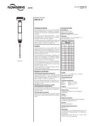
<strong>NRG</strong> <strong>16</strong>-<strong>38</strong> S<br />
<strong>Water</strong> <strong>Level</strong> <strong>Limiter</strong> <strong>with</strong><br />
<strong>Level</strong> <strong>Electrode</strong><br />
<strong>NRG</strong> <strong>16</strong>-<strong>38</strong> S, <strong>NRG</strong> <strong>16</strong>-39 S<br />
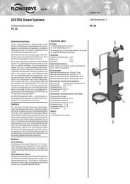
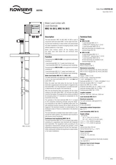
Description<br />
The level electrode <strong>NRG</strong> <strong>16</strong>-<strong>38</strong>S, <strong>NRG</strong> <strong>16</strong>-39S is used in<br />
conjunction <strong>with</strong> level switch NRS 1-50 for water level limiting<br />
and level monitoring in steam boilers and (pressurised)<br />
hot-water installations on board of seagoing vessels, mobile<br />
offshore <strong>pl</strong>atforms or river boats.<br />
<strong>Water</strong> level limiters switch off the heating when<br />
the water level falls below the set minimum level<br />
(low water).<br />
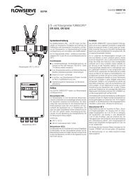
Function<br />
The level electrode <strong>NRG</strong> <strong>16</strong>-<strong>38</strong>S is an equipment combination<br />
consisting of<br />
1 level electrode <strong>NRG</strong> <strong>16</strong>-11 (water level limiter) and<br />
1 level transmitter <strong>NRG</strong>T 26-1S (continuous level monitoring).<br />
The level electrode <strong>NRG</strong> <strong>16</strong>-39S is an equipment combination<br />
consisting of<br />
2 level electrodes <strong>NRG</strong> <strong>16</strong>-11 (water level limiter) and<br />
1 level transmitter <strong>NRG</strong>T 26-1S (continuous level monitoring).<br />
<strong>Water</strong> level limiter <strong>NRG</strong> <strong>16</strong>-11 / NRS 1-50<br />
The water level limiter is an equipment combination consisting<br />
of one or two level electrode(s) <strong>NRG</strong> <strong>16</strong>-11 and one level<br />
switch NRS 1-50.<br />
When the water level falls below the low level, the level<br />
electrode is exposed and a low level alarm is triggered in the<br />
level switch NRS 1-50. This switchpoint “Low water level (LW)”<br />
is determined by the length of the electrode tip.<br />
After the de-energizing delay has elapsed, the two output<br />
contacts of the level switch NRS 1-50 will open the safety<br />
circuit for the heating. The equipment has a factory set default<br />
de-energizing delay of 15 seconds to compensate for the<br />
movements of the ship.<br />
The operation of the level electrode <strong>NRG</strong> <strong>16</strong>-11 is based<br />
on the conductive measuring princi<strong>pl</strong>e using the electrical<br />
conductivity of the water for signalling water level. The<br />
self-monitoring function ensures that an alarm will also be<br />
triggered if the electrode insulation is contaminated or has<br />
developed a leak or if there is a malfunction in the electrical<br />
connection.<br />
The level electrode is installed inside steam boilers or (pressurized)<br />
hot-water systems. The protective tube mounted on<br />
site ensures correct functioning.<br />
Continuous level monitoring <strong>NRG</strong>T 26-1S<br />
The level transmitter <strong>NRG</strong>T 26-1S is a compact-type system<br />
consisting of a capacitance level electrode <strong>with</strong> integrated<br />
level transmitter. The equipment works according to the<br />
capacitance measurement princi<strong>pl</strong>e and provides a level<br />
proportional measuring current of 4-20 mA. The level transmitter<br />
continuously monitors the liquid level in steam boilers<br />
or hot-water installations.<br />
STARLOCK ® is a registered trademark of<br />
Gebr. Titgemeyer GmbH & Co. KG, Osnabrück<br />
Data Sheet 810745-02<br />
Issue Date: 05/12<br />
Technical Data<br />
Design<br />
n <strong>NRG</strong> <strong>16</strong>-<strong>38</strong>S<br />
1 <strong>Level</strong> electrode <strong>NRG</strong> <strong>16</strong>-11<br />
1 STARLOCK ® retaining ring 11.5/4.8<br />
1 <strong>Level</strong> transmitter <strong>NRG</strong>T 26-1S<br />
Both level electrodes are installed in one<br />
common flange DN 100.<br />
n <strong>NRG</strong> <strong>16</strong>-<strong>38</strong>S<br />
2 <strong>Level</strong> electrodes <strong>NRG</strong> <strong>16</strong>-11<br />
2 STARLOCK ® retaining rings 11.5/4.8<br />
1 <strong>Level</strong> transmitter <strong>NRG</strong>T 26-1S<br />
All level electrodes are installed in one<br />
common flange DN 150.<br />
Service pressure<br />
PN 40, 32 bar at 2<strong>38</strong> °C<br />
Mechanical connection<br />
<strong>NRG</strong> <strong>16</strong>-<strong>38</strong> S: Flanged DN 100, PN 40, DIN 2635<br />
<strong>NRG</strong> <strong>16</strong>-39 S: Flanged DN 150, PN 40, DIN 2635<br />
Materials<br />
Flange: 1.0460 / A 105<br />
Screw-in body / measuring electrode:<br />
1.4571, X6CrNiMoTi17-12-2<br />
<strong>Electrode</strong> tip <strong>NRG</strong> <strong>16</strong>-11: 1.4401, X5CrNiMo17-12-2<br />
<strong>Electrode</strong> insulation <strong>NRG</strong> <strong>16</strong>-11: Gylon ®<br />
Spacer disc <strong>NRG</strong> <strong>16</strong>-11: PEEK<br />
Protection tube <strong>NRG</strong>T 26-1S: 1.0460 / A 105<br />
<strong>Electrode</strong> insulation <strong>NRG</strong>T 26-1S: PEEK<br />
Centering piece <strong>NRG</strong>T 26-1: PTFE<br />
Lengths available<br />
400 mm, 1000 mm, 1500 mm, 2000 mm<br />
<strong>Level</strong> electrode <strong>NRG</strong> <strong>16</strong>-11<br />
Electrical connection<br />
Four-pole connector, cable gland M <strong>16</strong><br />
Protection<br />
IP 65 to EN 60529<br />
Admissible ambient temperature<br />
Max. 70 °C<br />
<strong>Level</strong> transmitter <strong>NRG</strong>T 26-1S<br />
Sup<strong>pl</strong>y voltage<br />
24 V AC/DC.<br />
AC +/– 20% (19.2 to 28.8 V)<br />
DC +10 / –45% (13.5 to 26.5 Veff.)<br />
115 V +/– 10%, 50/60 Hz (optional)<br />
230 V +/– 10 %, 50/60 Hz (optional)<br />
Fuse<br />
external slow-blow 250 mA<br />
internal thermal fuse Tmax = 102°C<br />
Power consumption<br />
3 VA at 24 V DC<br />
5 VA at 24, 115, 230 V AC<br />
Output<br />
4 – 20 mA level proportional. Electrically insulated,<br />
max. load 500 Ω<br />
Response time to level changes<br />
<strong>NRG</strong>T 26-1: below 5 sec.<br />
P.T.O.
<strong>Water</strong> <strong>Level</strong> <strong>Limiter</strong> <strong>with</strong><br />
<strong>Level</strong> <strong>Electrode</strong><br />
<strong>NRG</strong> <strong>16</strong>-<strong>38</strong> S, <strong>NRG</strong> <strong>16</strong>-39 S<br />
Technical Data – continued –<br />
Indicators and adjustors<br />
2 red LEDS for “<strong>Level</strong> 0 %” or “<strong>Level</strong> 100 %“<br />
<strong>with</strong>in the measuring range,<br />
1 green LED for “<strong>Level</strong> between 0 % and 100 %“<br />
of the measuring range.<br />
1 Code switch for setting the measuring range.<br />
2 Adjustable resistors for small-percentage adjustment<br />
of the measuring range.<br />
2 Terminal lugs for voltage measurement<br />
Cable entry<br />
Cable gland <strong>with</strong> integral cable clamp<br />
2 x M20 x 1.5<br />
Protection<br />
IP 65 to DIN EN 60529<br />
Max. admissible ambient temperature<br />
Max. 70 °C<br />
Weight<br />
<strong>NRG</strong> <strong>16</strong>-<strong>38</strong> S: approx. 17 kg<br />
<strong>NRG</strong> <strong>16</strong>-39 S: approx. 25.5 kg<br />
Approvals<br />
GL 40 601-01 HH DNV A-12022<br />
LR 01 / 20026 (E2) KR HMB 06190-MS 001<br />
ABS 01-HG 227959-PDA NK TA 11017M<br />
BV 11400 / B0 BV CCS HBT04721062-3<br />
Important Notes<br />
n <strong>NRG</strong> <strong>16</strong>-11 (water level limiter)<br />
To connect the level electrode(s) use screened multi-core<br />
control cable <strong>with</strong> a min. conductor size of 0.5 mm 2 , e.g.<br />
LiYCY 4 x 0.5 mm 2 . Max. length 100 m <strong>with</strong> an electrical<br />
conductivity of the boiler water > 10 μS/cm at 25 °C.<br />
n <strong>NRG</strong>T 26-1S (level transmitter)<br />
To connect the sup<strong>pl</strong>y voltage <strong>pl</strong>ease use flexible cable.<br />
To connect the signal output use flexible and screened<br />
control cable, min. conductor size1,5 mm 2 and make sure<br />
that it is separated from the sup<strong>pl</strong>y voltage cable.<br />
Order & Enquiry Specification<br />
GESTRA level electrode <strong>NRG</strong> <strong>16</strong>-<strong>38</strong> S, length E ....... or<br />
GESTRA level electrode <strong>NRG</strong> <strong>16</strong>-39 S, length E .......<br />
Associated Equipment<br />
n GESTRA <strong>Level</strong> switch NRS 1-50 in conjunction <strong>with</strong><br />
level electrodes <strong>NRG</strong> <strong>16</strong>-11.<br />
n GESTRA Universal controller KS 92-1 in conjunction<br />
<strong>with</strong> level transmitter <strong>NRG</strong>T 26-1S.<br />
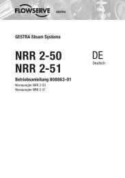
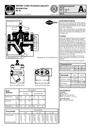
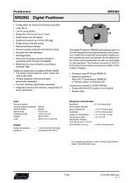
Legende<br />
1 Niveauelektrode <strong>NRG</strong> <strong>16</strong>-11<br />
2 Standby Eingang, 24 VDC für Anschluss<br />
Überwachungslogik SRL 6-50<br />
3 Istwert-Ausgang 4-20 mA, max. Bürde 500 Ω<br />
4 Versorgungsspannung 24 V AC/DC<br />
optional 115/230 V AC<br />
5 Temperatursicherung<br />
6 Erdungsschraube im Gehäuse<br />
Sup<strong>pl</strong>y in accordance <strong>with</strong> our general<br />
terms of business.<br />
GESTRA AG<br />
P. O. Box 10 54 60, D-28054 Bremen<br />
Münchener Str. 77 , D-28215 Bremen<br />
Tel. 0049 (0) 421 35 03 - 0, Fax 0049 (0) 421 35 03-393<br />
E-Mail gestra.ag@flowserve.com, Web www.gestra.de<br />
810745-02/05-2012cm (804173-03) · GESTRA AG · Bremen · Printed in Germany<br />
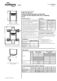
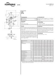
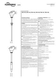
Dimensions<br />
(336)<br />
E<br />
<strong>NRG</strong> <strong>16</strong>-11 <strong>NRG</strong>T 26-1S<br />
F = 150<br />
Wiring diagrams<br />
(330.5) (363)<br />
<strong>NRG</strong> <strong>16</strong>-<strong>38</strong> S<br />
CEP CEP<br />
Length E Measuring<br />
range H<br />
358 mm 300<br />
462 mm 400<br />
568 mm 500<br />
673 mm 600<br />
779 mm 700<br />
884 mm 800<br />
989 mm 900<br />
1095 mm 1000<br />
1199 mm 1100<br />
1304 mm 1200<br />
1408 mm 1300<br />
1513 mm 1400<br />
<strong>16</strong>21 mm 1500<br />
1787 mm <strong>16</strong>00<br />
1899 mm 1700<br />
2011 mm 1800<br />
2124 mm 1900<br />
2236 mm 2000<br />
<strong>NRG</strong> <strong>16</strong>-39 S<br />
<strong>NRG</strong> <strong>16</strong>-11<br />
1 2<br />
<strong>NRG</strong> <strong>16</strong>-11<br />
1 2 3 6<br />
+ – 4<br />
(L) (N)<br />
NRS 1-50<br />
CEP Central earthing point in control cabinet<br />
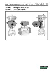
<strong>NRG</strong>T 26-1S<br />
(336)<br />
E<br />
<strong>NRG</strong>T 26-1<br />
<strong>NRG</strong>T 26-1S<br />
F = 150<br />
5