WT4090 Mounting Bracket Installation Instructions (p/n 72-92884-02 ...
WT4090 Mounting Bracket Installation Instructions (p/n 72-92884-02 ...
WT4090 Mounting Bracket Installation Instructions (p/n 72-92884-02 ...

Create successful ePaper yourself
Turn your PDF publications into a flip-book with our unique Google optimized e-Paper software.
<strong>WT4090</strong><br />
<strong>Mounting</strong> <strong>Bracket</strong><br />
<strong>Installation</strong> <strong>Instructions</strong><br />
Motorola reserves the right to make changes to any product to improve reliability,<br />
function, or design.<br />
Motorola does not assume any product liability arising out of, or in connection with, the<br />
application or use of any product, circuit, or application described herein.<br />
No license is granted, either expressly or by implication, estoppel, or otherwise under<br />
any patent right or patent, covering or relating to any combination, system, apparatus,<br />
machine, material, method, or process in which Motorola products might be used. An<br />
implied license exists only for equipment, circuits, and subsystems contained in<br />
Motorola products.<br />
MOTOROLA, the Stylized M Logo and Symbol and the Symbol logo are registered<br />
trademarks of Motorola, Inc. Other product names mentioned in this manual may be<br />
trademarks or registered trademarks of their respective companies and are hereby<br />
acknowledged.<br />
Warranty<br />
For the complete Motorola hardware product warranty statement, go to:<br />
http://www.symbol.com/warranty.<br />
Patents<br />
This product is covered by one or more patents. For patent information go to:<br />
http://www.symbol.com/patents.<br />
Motorola, Inc.<br />
One Motorola Plaza<br />
Holtsville, New York 11742, USA<br />
1-800-927-9626<br />
http://www.symbol.com<br />
MOTOROLA and the Stylized M Logo and Symbol and the Symbol logo<br />
are registered in the U.S. Patent and Trademark Office. All other product<br />
or service names are the property of their registered owners.<br />
© Motorola, Inc. 2007<br />
<strong>72</strong>-<strong>92884</strong>-<strong>02</strong> Revision A — December 2007<br />
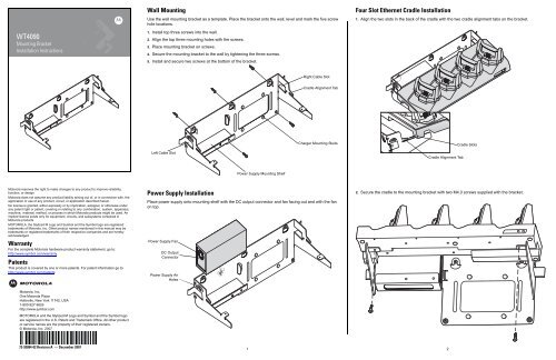
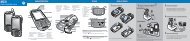
Wall <strong>Mounting</strong><br />
Use the wall mounting bracket as a template. Place the bracket onto the wall, level and mark the five screw<br />
hole locations.<br />
1. Install top three screws into the wall.<br />
2. Align the top three mounting holes with the screws.<br />
3. Place mounting bracket on screws.<br />
4. Secure the mounting bracket to the wall by tightening the three screws.<br />
5. Install and secure two screws at the bottom of the bracket.<br />
Left Cable Slot<br />
Power Supply <strong>Installation</strong><br />
Place power supply onto mounting shelf with the DC output connector and fan facing out and with the fan<br />
on top.<br />
Power Supply Fan<br />
DC Output<br />
Connector<br />
Power Supply Air<br />
Holes<br />
Power Supply <strong>Mounting</strong> Shelf<br />
Right Cable Slot<br />
Cradle Alignment Tab<br />
Charger <strong>Mounting</strong> Studs<br />
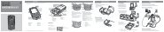
Four Slot Ethernet Cradle <strong>Installation</strong><br />
1. Align the two slots in the back of the cradle with the two cradle alignment tabs on the bracket.<br />
Cradle Alignment Tab<br />
2. Secure the cradle to the mounting bracket with two M4.0 screws supplied with the bracket.<br />
1 2<br />
Cradle Slots
Four Slot Battery Charger <strong>Installation</strong><br />
The Four Slot Spare Batter Charger has four mounting slots on the back. Around the slots are<br />
guides that assist in proper alignment of the charger onto the mounting bracket. Gravity holds<br />
the charger in place.<br />
Position the charger over the mounting studs and slide the charger into place.<br />
Ensure that the charger is seated properly.<br />
Wiring<br />
The AC line cord provides AC power to the power supply. The mounting bracket power cable<br />
provides power from the power supply to the Four Slot Ethernet cradle and the Four Slot<br />
Spare Battery Charger.<br />
Ensure that the AC line cord is long enough to reach from the AC power source to the power<br />
supply.<br />
1. Route the AC line cord through the right cable slot of the bracket.<br />
2. Plug the AC line cord into the power supply AC input connector.<br />
3. Route the power supply connector of the power cable through the cradle channel and out<br />
the left side of the cradle.<br />
4. Plug the power cable connector into the DC output connector on the power supply.<br />
5. Plug the cradle power plug into the Four Slot Ethernet cradle input power connector.<br />
6. Plug the charger power plug onto the Four Slot Spare battery Charger input power<br />
connector.<br />
7. Route the cables as shown.<br />
<strong>Mounting</strong> Studs<br />
8. Use two tie-wraps to secure the power cable Y connection to the power supply mounting<br />
shelf.<br />
3<br />
<strong>Mounting</strong> Slots<br />
Cradle Power Plug<br />
Tie-Wraps<br />
9. Use one tie-wrap to secure the AC line cord to the mounting bracket.<br />
10.Use two tie-wraps to secure the charger power lead and the AC line cord together as shown<br />
below.<br />
Charger Power Lead<br />
Tie-Wraps<br />
AC Line Cord<br />
11.Plug the AC line cord into an AC power source.<br />
Placing a Battery in the Charger<br />
Right Cable Slot<br />
Charger Power<br />
Plug<br />
When placing a spare battery into the Four Slot Spare Battery Charger, ensure proper<br />
orientation of the battery.<br />
Tie-Wrap<br />
<strong>Mounting</strong> Multiple <strong>Bracket</strong>s<br />
When installing multiple brackets on a wall:<br />
• Each mounting bracket must be 25.4 cm (10 in.) from the top of one bracket to the top of<br />
the next bracket.<br />
• The bottom of the last bracket must be at least 61 cm (24 in.) from the floor.<br />
• When mounting brackets next to each other the tabs must at least touch each other to<br />
ensure minimum distance between brackets.<br />
Position Tabs<br />
Together to Ensure<br />
Minimum Distance<br />
25.4 cm<br />
10 in.<br />
61 cm<br />
24 in.<br />
4 5


![MC55 Regulatory Guide [Spanish] (P/N 72-108860 ... - Enterprise](https://img.yumpu.com/14574395/1/190x133/mc55-regulatory-guide-spanish-p-n-72-108860-enterprise.jpg?quality=85)
![ES400 Regulatory Guide [Spanish] (P/N 72-134312-01ES Rev. A)](https://img.yumpu.com/14415156/1/190x127/es400-regulatory-guide-spanish-p-n-72-134312-01es-rev-a.jpg?quality=85)
![MC35 Regulatory Information [Spanish] - Symbol](https://img.yumpu.com/14415086/1/190x143/mc35-regulatory-information-spanish-symbol.jpg?quality=85)