Series 3000 Application Programmer's Guide
Series 3000 Application Programmer's Guide
Series 3000 Application Programmer's Guide

Create successful ePaper yourself
Turn your PDF publications into a flip-book with our unique Google optimized e-Paper software.
<strong>Series</strong> <strong>3000</strong><br />
<strong>Application</strong> Programmer’s <strong>Guide</strong>
2<br />
<strong>Series</strong> <strong>3000</strong> <strong>Application</strong> Programmer’s <strong>Guide</strong><br />
70-16308-03<br />
Revision A — April 2000<br />
Symbol Technologies, Inc. One Symbol Plaza, Holtsville N.Y. 11742
<strong>Series</strong> <strong>3000</strong><br />
<strong>Application</strong> Programmer’s <strong>Guide</strong><br />
70-16308-03<br />
Revision A<br />
April, 2000
© 1996-2000 by Symbol Technologies, Inc. All rights reserved.<br />
No part of this publication may be reproduced or used in any form, or by any electrical or<br />
mechanical means, without permission in writing from Symbol. This includes electronic<br />
or mechanical means, such as photocopying, recording, or information storage and<br />
retrieval systems. The material in this manual is subject to change without notice.<br />
The software is provided strictly on an “as is” basis. All software, including firmware,<br />
furnished to the user is on a licensed basis. Symbol grants to the user a non-transferable<br />
and non-exclusive license to use each software or firmware program delivered hereunder<br />
(licensed program). Except as noted below, such license may not be assigned, sublicensed,<br />
or otherwise transferred by the user without prior written consent of Symbol. No right to<br />
copy a licensed program in whole or in part is granted, except as permitted under<br />
copyright law. The user shall not modify, merge, or incorporate any form or portion of a<br />
licensed program with other program material, create a derivative work from a licensed<br />
program, or use a licensed program in a network without written permission from Symbol.<br />
The user agrees to maintain Symbol’s copyright notice on the licensed programs delivered<br />
hereunder, and to include the same on any authorized copies it makes, in whole or in part.<br />
The user agrees not to decompile, disassemble, decode, or reverse engineer any licensed<br />
program delivered to the user or any portion thereof.<br />
Symbol reserves the right to make changes to any software or product to improve<br />
reliability, function, or design.<br />
Symbol does not assume any product liability arising out of, or in connection with, the<br />
application or use of any product, circuit, or application described herein.<br />
No license is granted, either expressly or by implication, estoppel, or otherwise under any<br />
Symbol Technologies, Inc., intellectual property rights. An implied license only exists for<br />
equipment, circuits, and subsystems contained in Symbol products.<br />
Symbol and Spectrum One are registered trademarks of Symbol Technologies, Inc.<br />
Other product names mentioned in this manual may be trademarks or registered<br />
trademarks of their respective companies and are hereby acknowledged.<br />
Symbol Technologies, Inc.<br />
One Symbol Plaza<br />
Holtsville, NY 11742-1300<br />
http://www.symbol.com<br />
iv
Contents<br />
Chapter. About This Manual<br />
Introduction and Overview . . . . . . . . . . . . . . . . . . . . . . . . . . . . . . . . . . . . . . . . . . . . . . . . . . . . . . . . . vii<br />
Chapter Descriptions. . . . . . . . . . . . . . . . . . . . . . . . . . . . . . . . . . . . . . . . . . . . . . . . . . . . . . . . . . . . . . . .ix<br />
Notational Conventions. . . . . . . . . . . . . . . . . . . . . . . . . . . . . . . . . . . . . . . . . . . . . . . . . . . . . . . . . . . . .xi<br />
Sample Programs . . . . . . . . . . . . . . . . . . . . . . . . . . . . . . . . . . . . . . . . . . . . . . . . . . . . . . . . . . . . . . . . . . xii<br />
Related Documentation. . . . . . . . . . . . . . . . . . . . . . . . . . . . . . . . . . . . . . . . . . . . . . . . . . . . . . . . . . . . . xii<br />
Chapter 1. Installing the ADK<br />
Introduction . . . . . . . . . . . . . . . . . . . . . . . . . . . . . . . . . . . . . . . . . . . . . . . . . . . . . . . . . . . . . . . . . . . . . 1-3<br />
System Requirements . . . . . . . . . . . . . . . . . . . . . . . . . . . . . . . . . . . . . . . . . . . . . . . . . . . . . . . . . . . . . 1-4<br />
Installing the ADK Software . . . . . . . . . . . . . . . . . . . . . . . . . . . . . . . . . . . . . . . . . . . . . . . . . . . . . . . 1-5<br />
Modifying C Libraries. . . . . . . . . . . . . . . . . . . . . . . . . . . . . . . . . . . . . . . . . . . . . . . . . . . . . . . . . . . . . 1-8<br />
Configuring the PC Display . . . . . . . . . . . . . . . . . . . . . . . . . . . . . . . . . . . . . . . . . . . . . . . . . . . . . . . . 1-9<br />
Connecting a Terminal to Your Development System. . . . . . . . . . . . . . . . . . . . . . . . . . . . . . . . . 1-10<br />
Chapter 2. Programming a <strong>Series</strong> <strong>3000</strong> Terminal<br />
Introduction . . . . . . . . . . . . . . . . . . . . . . . . . . . . . . . . . . . . . . . . . . . . . . . . . . . . . . . . . . . . . . . . . . . . . 2-3<br />
Creating and Downloading a Program . . . . . . . . . . . . . . . . . . . . . . . . . . . . . . . . . . . . . . . . . . . . . . 2-4<br />
The Terminal Operating Environment . . . . . . . . . . . . . . . . . . . . . . . . . . . . . . . . . . . . . . . . . . . . . . . 2-8<br />
Moving On . . . . . . . . . . . . . . . . . . . . . . . . . . . . . . . . . . . . . . . . . . . . . . . . . . . . . . . . . . . . . . . . . . . . . 2-14<br />
Chapter 3. Terminal Environment<br />
Introduction . . . . . . . . . . . . . . . . . . . . . . . . . . . . . . . . . . . . . . . . . . . . . . . . . . . . . . . . . . . . . . . . . . . . . 3-3<br />
Hardware Environment . . . . . . . . . . . . . . . . . . . . . . . . . . . . . . . . . . . . . . . . . . . . . . . . . . . . . . . . . . . 3-3<br />
Power Management. . . . . . . . . . . . . . . . . . . . . . . . . . . . . . . . . . . . . . . . . . . . . . . . . . . . . . . . . . . . . . 3-10<br />
PC BIOS Compatibility . . . . . . . . . . . . . . . . . . . . . . . . . . . . . . . . . . . . . . . . . . . . . . . . . . . . . . . . . . . 3-11<br />
Chapter 4. NVM Configuration<br />
Introduction . . . . . . . . . . . . . . . . . . . . . . . . . . . . . . . . . . . . . . . . . . . . . . . . . . . . . . . . . . . . . . . . . . . . . 4-3<br />
System Memory Structure . . . . . . . . . . . . . . . . . . . . . . . . . . . . . . . . . . . . . . . . . . . . . . . . . . . . . . . . . 4-5<br />
Basic NVM Configurations. . . . . . . . . . . . . . . . . . . . . . . . . . . . . . . . . . . . . . . . . . . . . . . . . . . . . . . . . 4-7<br />
Storing Programs . . . . . . . . . . . . . . . . . . . . . . . . . . . . . . . . . . . . . . . . . . . . . . . . . . . . . . . . . . . . . . . . . 4-9<br />
Building an NVM Image. . . . . . . . . . . . . . . . . . . . . . . . . . . . . . . . . . . . . . . . . . . . . . . . . . . . . . . . . . 4-10<br />
Sample USRCFG Response Files . . . . . . . . . . . . . . . . . . . . . . . . . . . . . . . . . . . . . . . . . . . . . . . . . . . 4-20<br />
NVM Image Size . . . . . . . . . . . . . . . . . . . . . . . . . . . . . . . . . . . . . . . . . . . . . . . . . . . . . . . . . . . . . . . . 4-23<br />
iii
iv<br />
Chapter 5. Terminal Initialization<br />
Introduction . . . . . . . . . . . . . . . . . . . . . . . . . . . . . . . . . . . . . . . . . . . . . . . . . . . . . . . . . . . . . . . . . . . . . 5-3<br />
Running BLDINIT . . . . . . . . . . . . . . . . . . . . . . . . . . . . . . . . . . . . . . . . . . . . . . . . . . . . . . . . . . . . . . . . 5-4<br />
Font Table Selection. . . . . . . . . . . . . . . . . . . . . . . . . . . . . . . . . . . . . . . . . . . . . . . . . . . . . . . . . . . . . . . 5-8<br />
Files Linked with BLDINIT . . . . . . . . . . . . . . . . . . . . . . . . . . . . . . . . . . . . . . . . . . . . . . . . . . . . . . . . 5-8<br />
Chapter 6. Managing Files<br />
Introduction . . . . . . . . . . . . . . . . . . . . . . . . . . . . . . . . . . . . . . . . . . . . . . . . . . . . . . . . . . . . . . . . . . . . . 6-3<br />
UBASIC File Manager Features . . . . . . . . . . . . . . . . . . . . . . . . . . . . . . . . . . . . . . . . . . . . . . . . . . . . . 6-4<br />
Using the File Manager . . . . . . . . . . . . . . . . . . . . . . . . . . . . . . . . . . . . . . . . . . . . . . . . . . . . . . . . . . . . 6-8<br />
Loading the File Manager. . . . . . . . . . . . . . . . . . . . . . . . . . . . . . . . . . . . . . . . . . . . . . . . . . . . . . . . . 6-10<br />
DOS File Management APIs. . . . . . . . . . . . . . . . . . . . . . . . . . . . . . . . . . . . . . . . . . . . . . . . . . . . . . . 6-13<br />
Microsoft Visual C Runtime Functions. . . . . . . . . . . . . . . . . . . . . . . . . . . . . . . . . . . . . . . . . . . . . . 6-14<br />
Sample Programs . . . . . . . . . . . . . . . . . . . . . . . . . . . . . . . . . . . . . . . . . . . . . . . . . . . . . . . . . . . . . . . . 6-16<br />
Chapter 7. Managing Memory<br />
Introduction . . . . . . . . . . . . . . . . . . . . . . . . . . . . . . . . . . . . . . . . . . . . . . . . . . . . . . . . . . . . . . . . . . . . . 7-3<br />
Program Memory Requirements . . . . . . . . . . . . . . . . . . . . . . . . . . . . . . . . . . . . . . . . . . . . . . . . . . . . 7-4<br />
Maximizing Memory Use . . . . . . . . . . . . . . . . . . . . . . . . . . . . . . . . . . . . . . . . . . . . . . . . . . . . . . . . . . 7-6<br />
Handling Low-Memory Situations . . . . . . . . . . . . . . . . . . . . . . . . . . . . . . . . . . . . . . . . . . . . . . . . . . 7-8<br />
Managing Available Memory . . . . . . . . . . . . . . . . . . . . . . . . . . . . . . . . . . . . . . . . . . . . . . . . . . . . . . 7-9<br />
EMS . . . . . . . . . . . . . . . . . . . . . . . . . . . . . . . . . . . . . . . . . . . . . . . . . . . . . . . . . . . . . . . . . . . . . . . . . . . 7-13<br />
Sample Programs . . . . . . . . . . . . . . . . . . . . . . . . . . . . . . . . . . . . . . . . . . . . . . . . . . . . . . . . . . . . . . . . 7-16<br />
Chapter 8. Display Handling<br />
Introduction . . . . . . . . . . . . . . . . . . . . . . . . . . . . . . . . . . . . . . . . . . . . . . . . . . . . . . . . . . . . . . . . . . . . . 8-3<br />
Improving Display Performance . . . . . . . . . . . . . . . . . . . . . . . . . . . . . . . . . . . . . . . . . . . . . . . . . . . 8-12<br />
Cursor Control . . . . . . . . . . . . . . . . . . . . . . . . . . . . . . . . . . . . . . . . . . . . . . . . . . . . . . . . . . . . . . . . . . 8-16<br />
Miscellaneous Screen Operations . . . . . . . . . . . . . . . . . . . . . . . . . . . . . . . . . . . . . . . . . . . . . . . . . . 8-18<br />
ANSI Support . . . . . . . . . . . . . . . . . . . . . . . . . . . . . . . . . . . . . . . . . . . . . . . . . . . . . . . . . . . . . . . . . . . 8-19<br />
Display Fonts . . . . . . . . . . . . . . . . . . . . . . . . . . . . . . . . . . . . . . . . . . . . . . . . . . . . . . . . . . . . . . . . . . . 8-21<br />
Font Builder . . . . . . . . . . . . . . . . . . . . . . . . . . . . . . . . . . . . . . . . . . . . . . . . . . . . . . . . . . . . . . . . . . . . 8-22<br />
Making a Font TSR . . . . . . . . . . . . . . . . . . . . . . . . . . . . . . . . . . . . . . . . . . . . . . . . . . . . . . . . . . . . . . 8-31<br />
Chapter 9. Keyboard Processing<br />
Introduction . . . . . . . . . . . . . . . . . . . . . . . . . . . . . . . . . . . . . . . . . . . . . . . . . . . . . . . . . . . . . . . . . . . . . 9-3<br />
Keyboard Operation . . . . . . . . . . . . . . . . . . . . . . . . . . . . . . . . . . . . . . . . . . . . . . . . . . . . . . . . . . . . . . 9-4<br />
Spanish Language Support on <strong>Series</strong> <strong>3000</strong>. . . . . . . . . . . . . . . . . . . . . . . . . . . . . . . . . . . . . . . . . . . 9-12<br />
Processing Key Input. . . . . . . . . . . . . . . . . . . . . . . . . . . . . . . . . . . . . . . . . . . . . . . . . . . . . . . . . . . . . 9-14<br />
Using DOS I/O Control Functions . . . . . . . . . . . . . . . . . . . . . . . . . . . . . . . . . . . . . . . . . . . . . . . . . 9-21<br />
Conserving Power . . . . . . . . . . . . . . . . . . . . . . . . . . . . . . . . . . . . . . . . . . . . . . . . . . . . . . . . . . . . . . . 9-23
Using the Keyboard Mapping Utility . . . . . . . . . . . . . . . . . . . . . . . . . . . . . . . . . . . . . . . . . . . . . . . 9-28<br />
Using a Translation Table. . . . . . . . . . . . . . . . . . . . . . . . . . . . . . . . . . . . . . . . . . . . . . . . . . . . . . . . . 9-36<br />
Sample Programs . . . . . . . . . . . . . . . . . . . . . . . . . . . . . . . . . . . . . . . . . . . . . . . . . . . . . . . . . . . . . . . . 9-37<br />
Chapter 10. Scanning<br />
Introduction . . . . . . . . . . . . . . . . . . . . . . . . . . . . . . . . . . . . . . . . . . . . . . . . . . . . . . . . . . . . . . . . . . . . 10-3<br />
Changes in This Release . . . . . . . . . . . . . . . . . . . . . . . . . . . . . . . . . . . . . . . . . . . . . . . . . . . . . . . . . . 10-3<br />
The Scanning Interface . . . . . . . . . . . . . . . . . . . . . . . . . . . . . . . . . . . . . . . . . . . . . . . . . . . . . . . . . . . 10-6<br />
Loading SCAN<strong>3000</strong> . . . . . . . . . . . . . . . . . . . . . . . . . . . . . . . . . . . . . . . . . . . . . . . . . . . . . . . . . . . . . . 10-9<br />
Loading SCAN3500 . . . . . . . . . . . . . . . . . . . . . . . . . . . . . . . . . . . . . . . . . . . . . . . . . . . . . . . . . . . . . 10-11<br />
Adding Scanning to an <strong>Application</strong> . . . . . . . . . . . . . . . . . . . . . . . . . . . . . . . . . . . . . . . . . . . . . . . 10-12<br />
BLDSCAN.EXE. . . . . . . . . . . . . . . . . . . . . . . . . . . . . . . . . . . . . . . . . . . . . . . . . . . . . . . . . . . . . . . . . 10-14<br />
Parameter Descriptions. . . . . . . . . . . . . . . . . . . . . . . . . . . . . . . . . . . . . . . . . . . . . . . . . . . . . . . . . . 10-32<br />
Parameter Menu Scanning . . . . . . . . . . . . . . . . . . . . . . . . . . . . . . . . . . . . . . . . . . . . . . . . . . . . . . . 10-39<br />
Modifying the Scanner, Reader, and Decoders . . . . . . . . . . . . . . . . . . . . . . . . . . . . . . . . . . . . . . 10-77<br />
Creating the Initialization File . . . . . . . . . . . . . . . . . . . . . . . . . . . . . . . . . . . . . . . . . . . . . . . . . . . 10-88<br />
Updating the Scanner, Readers, and Decoders . . . . . . . . . . . . . . . . . . . . . . . . . . . . . . . . . . . . . . 10-89<br />
Chapter 11. Data Communications<br />
Introduction . . . . . . . . . . . . . . . . . . . . . . . . . . . . . . . . . . . . . . . . . . . . . . . . . . . . . . . . . . . . . . . . . . . . 11-3<br />
Using the URM API. . . . . . . . . . . . . . . . . . . . . . . . . . . . . . . . . . . . . . . . . . . . . . . . . . . . . . . . . . . . . 11-12<br />
Using the DR DOS API . . . . . . . . . . . . . . . . . . . . . . . . . . . . . . . . . . . . . . . . . . . . . . . . . . . . . . . . . . 11-30<br />
Using the BIOS API . . . . . . . . . . . . . . . . . . . . . . . . . . . . . . . . . . . . . . . . . . . . . . . . . . . . . . . . . . . . . 11-34<br />
Sample Communication Programs . . . . . . . . . . . . . . . . . . . . . . . . . . . . . . . . . . . . . . . . . . . . . . . . 11-36<br />
Managing Terminal Resources . . . . . . . . . . . . . . . . . . . . . . . . . . . . . . . . . . . . . . . . . . . . . . . . . . . 11-41<br />
Unattended Communications . . . . . . . . . . . . . . . . . . . . . . . . . . . . . . . . . . . . . . . . . . . . . . . . . . . . 11-43<br />
Communicating Through a Cradle . . . . . . . . . . . . . . . . . . . . . . . . . . . . . . . . . . . . . . . . . . . . . . . . 11-44<br />
Communication Problems . . . . . . . . . . . . . . . . . . . . . . . . . . . . . . . . . . . . . . . . . . . . . . . . . . . . . . . 11-50<br />
Remote PC Communication Software . . . . . . . . . . . . . . . . . . . . . . . . . . . . . . . . . . . . . . . . . . . . . 11-54<br />
Chapter 12. Writing Resident Programs<br />
Introduction . . . . . . . . . . . . . . . . . . . . . . . . . . . . . . . . . . . . . . . . . . . . . . . . . . . . . . . . . . . . . . . . . . . . 12-3<br />
Types of Resident Programs. . . . . . . . . . . . . . . . . . . . . . . . . . . . . . . . . . . . . . . . . . . . . . . . . . . . . . . 12-5<br />
Separating the Data from the Code. . . . . . . . . . . . . . . . . . . . . . . . . . . . . . . . . . . . . . . . . . . . . . . . . 12-8<br />
Calling a Resident Program . . . . . . . . . . . . . . . . . . . . . . . . . . . . . . . . . . . . . . . . . . . . . . . . . . . . . . . 12-9<br />
Memory Models for Resident Programs . . . . . . . . . . . . . . . . . . . . . . . . . . . . . . . . . . . . . . . . . . . 12-10<br />
Writing Resident Programs . . . . . . . . . . . . . . . . . . . . . . . . . . . . . . . . . . . . . . . . . . . . . . . . . . . . . . 12-11<br />
The Resident Library Builder. . . . . . . . . . . . . . . . . . . . . . . . . . . . . . . . . . . . . . . . . . . . . . . . . . . . . 12-14<br />
Appendix A. Monarch Printer Drivers<br />
Appendix Contents . . . . . . . . . . . . . . . . . . . . . . . . . . . . . . . . . . . . . . . . . . . . . . . . . . . . . . . . . . . . . . . A-1<br />
Introduction . . . . . . . . . . . . . . . . . . . . . . . . . . . . . . . . . . . . . . . . . . . . . . . . . . . . . . . . . . . . . . . . . . . . . A-3<br />
v
vi<br />
Installing the Monarch 9490 Printer Driver . . . . . . . . . . . . . . . . . . . . . . . . . . . . . . . . . . . . . . . . . . . A-3<br />
Installing the Monarch 9450 Printer Driver . . . . . . . . . . . . . . . . . . . . . . . . . . . . . . . . . . . . . . . . . . . A-4<br />
Index
About This Manual<br />
Introduction and Overview<br />
The <strong>Series</strong> <strong>3000</strong> <strong>Application</strong> <strong>Programmer's</strong> <strong>Guide</strong> is written for programmers who<br />
are using the <strong>Application</strong> Development Kit (ADK) to create applications for<br />
Symbol Technologies <strong>Series</strong>’ <strong>Series</strong> <strong>3000</strong> terminals.<br />
The ADK constitutes the primary application development environment<br />
provided by Symbol Technologies and consists of a large number and wide<br />
variety of programming tools and resources. The most important tool is a series<br />
of C libraries that ptovide a variety of application programming interfaces<br />
(APIs). The ADK supports Microsoft Visual C++ 1.5 and 1.52 as the<br />
development language. This manual assumes that you are using Visual C++ as<br />
your primary development vehicle and are already thoughoughly familiar<br />
with it. It also assumes that you are familiar with programming in a PC<br />
environment and have a good knowledge of DOS operations.<br />
This application programmer’s guide describes the use of ADK tools to write<br />
applications for <strong>Series</strong> <strong>3000</strong> terminals. Its focus is on those aspects of<br />
programming <strong>Series</strong> <strong>3000</strong> terminals that are different from programming a<br />
typical PC. It is not a standalone document, however; it must be used in<br />
conjunction with three other documents supplied with the ADK. These other<br />
documents provide detailed descriptions of libraries, utilities , APIs, etc.<br />
referred to in this guide. They should be kept readily available for easy<br />
reference when you are using this manual to write applications.<br />
The three reference manuals provided with the ADK for use with this<br />
programmer’s guide are:<br />
<strong>Series</strong> <strong>3000</strong> <strong>Application</strong> Programmer’s Reference Manual<br />
This manual describes C language interface libraries included in the ADK.<br />
Of these the largest libraries are the BIOS and DOS function libraries. By<br />
vii
viii<br />
<strong>Series</strong> <strong>3000</strong> <strong>Application</strong> Programmer’s <strong>Guide</strong><br />
using the functions in these libraries, the programmer has C language<br />
access to the features of the <strong>Series</strong> <strong>3000</strong> terminals necessary to integrate the<br />
terminal into the target application. These central features include bar<br />
code scanning and communications, including Spectrum One ® radio<br />
communications. Additional libraries allow for further enhancements,<br />
such as graphics display capabilities and custom keyboard definitions.<br />
In addition to the libraries, this reference includes descriptions of a<br />
number of utilities also included in the ADK. Some utilities are special<br />
purpose programs that can be included in the terminal environment,<br />
usually running as TSRs (Terminate and Stay Resident programs). Others<br />
are programming tools necessary to build files or programs to run on the<br />
<strong>Series</strong> <strong>3000</strong> terminal.<br />
It also describes a modem command set that includes commands<br />
supported by the IM3, IM4, IM5, IM6 and IM7 internal modems.<br />
<strong>Series</strong> <strong>3000</strong> <strong>Application</strong> Developer’s Library<br />
This library routines described in this reference facilitate the development<br />
of 'C' programs to execute on the Symbol Technologies <strong>Series</strong> <strong>3000</strong><br />
terminals. These routines are supplied as a supplement to ADK libraries<br />
and to Microsoft 'C' libraries and make calls to those libraries.<br />
The functions supplied cover many aspects of typical hand-held<br />
computer applications, including file data management, keyboard entry,<br />
scanning, screen output, sound, data manipulation, communications,<br />
program update and memory status.<br />
<strong>Series</strong> <strong>3000</strong> System Software Manual<br />
This reference manual provides detailed information on low level utilities<br />
that may be required for programming <strong>Series</strong> <strong>3000</strong> terminals at system<br />
level. It will be useful to the application programmer or software engineer<br />
who, while writing applications for <strong>Series</strong> <strong>3000</strong> terminals, must use lowlevel<br />
function calls to:<br />
- develop or modify higher level structures<br />
- access special features of the <strong>Series</strong> <strong>3000</strong> terminal that are available<br />
only through these low level functions
Chapter Descriptions<br />
About This Manual<br />
The following brief chapter descriptions will help you focus on your area of<br />
interest:<br />
Chapter 1, Installing the ADK, describes the installation procedure for the ADK, system<br />
requirements, and set-up options.<br />
Chapter 2, Programming a <strong>Series</strong> <strong>3000</strong> Terminal, introduces the processes<br />
involved in writing a C program for a <strong>Series</strong> <strong>3000</strong> terminal. It deals primarily<br />
with the following three processes:<br />
1.Writing and compiling an application program<br />
2.Building and downloading an operating environment into the terminal<br />
NVM (Non-Volatile Memory)<br />
3.Downloading the program to the terminal<br />
Chapter 3, Terminal Environment, lists all of the models of <strong>Series</strong> <strong>3000</strong> hand-held<br />
computers and describes the features associated with and the options available<br />
on each model.<br />
Chapter 4, NVM Configuration, describes different configuration options<br />
available on <strong>Series</strong> <strong>3000</strong> terminals.<br />
Chapter 5, Terminal Initialization, describes the Terminal Initialization Tool<br />
(BLDINIT.EXE), which builds the INIT.EXE initialization program for <strong>Series</strong><br />
<strong>3000</strong> terminals.<br />
Chapter 6, Managing Files, focuses primarily on Symbol’s UBASIC File<br />
Management Resource for <strong>Series</strong> <strong>3000</strong> terminals. This file manager provides<br />
high level file storage and access methods for fast and efficient file<br />
management. (See also the chapter on the UBASIC Record Manager in the <strong>Series</strong><br />
<strong>3000</strong> <strong>Application</strong> Programmer’s Reference Manual, which is supplied with the<br />
ADK.)<br />
Chapter 7, Managing Memory, describes a number of methods for managing how<br />
your applications use memory. It also some ways of solving memory<br />
limitations.<br />
ix
x<br />
<strong>Series</strong> <strong>3000</strong> <strong>Application</strong> Programmer’s <strong>Guide</strong><br />
Chapter 8, Display Handling, describes a number of BIOS tools that have been<br />
provided for managing displays on <strong>Series</strong> <strong>3000</strong> terminals, especially the use of<br />
physical, virtual, and logical display screens.<br />
Chapter 9, Keyboard Processing, discusses the processing of both keyboard and<br />
scanned input by the console driver. The new Keyboard Mapper utility—<br />
which provides a graphical interface to allow for quick and intuitive<br />
application keyboard design—is just one of the topics discussed in this chapter.<br />
Chapter 10, Scanning, provides information on the wide range of bar code<br />
scanning input devices and symbologies which are supported by the <strong>Series</strong><br />
<strong>3000</strong> terminals. (See also the Console/Scanner Device Driver chapter in the <strong>Series</strong><br />
<strong>3000</strong> System Software Manual, which is supplied with the ADK.)<br />
Chapter 11, Data Communications, addresses the issues associated with direct<br />
connect and modem data communications via <strong>Series</strong> <strong>3000</strong> terminals.<br />
Chapter 12, Writing Resident Programs, explains how to build both NVM (nonvolatile<br />
memory) and split resident programs, which can be used in<br />
developing library files. This chapter also includes instructions on building<br />
libraries.<br />
Appendix A, Monarch Printer Drivers, explains how to install the Monarch 9450<br />
and 9490 Printer Drivers.
Notational Conventions<br />
The following conventions are used in this manual:<br />
About This Manual<br />
"Operator" and "User" refer to anyone using an application on a <strong>Series</strong><br />
<strong>3000</strong> hand-held computer.<br />
"PC" refers to the IBM personal computer or compatible system that you<br />
are using to develop applications.<br />
"Terminal" refers to a <strong>Series</strong> <strong>3000</strong> hand-held computer.<br />
"You" refers to the programmer who is using this manual as an aid in<br />
creating applications for <strong>Series</strong> <strong>3000</strong> terminals.<br />
Keystrokes in bold type within angle brackets indicate keystrokes on the<br />
development PC or on a <strong>Series</strong> <strong>3000</strong> terminal. For example:<br />
Select the key on the terminal to access on-line help.<br />
Bold type is used:<br />
- for the names of services, functions, and commands<br />
- to identify menu items and input or text fields on a terminal screen<br />
- to display command lines<br />
Note: Program command names and required<br />
parameters appear without brackets; optional<br />
parameters appear in square [] brackets.<br />
Italics are used:<br />
- for the names of parameters in function prototypes and variable names<br />
in usage and syntax descriptions<br />
- to highlight specific items in the general text<br />
- to identify chapters and sections in this and related documents<br />
Square brackets [] in a command line enclose optional command-line<br />
parameters.<br />
The piping symbol | has the effect of "or" when it is used to separate<br />
command-line parameters on a command line; i.e., it separates alternative<br />
values for parameters.<br />
xi
xii<br />
<strong>Series</strong> <strong>3000</strong> <strong>Application</strong> Programmer’s <strong>Guide</strong><br />
Bullets (•) indicate:<br />
- action items<br />
- lists of alternatives<br />
- lists of required steps that are not necessarily sequential<br />
Sequential lists (e.g., those that describe step-by-step procedures) appear<br />
as numbered lists.<br />
Sample Programs<br />
Sample programs for this manual are provided as a hypertext document in the<br />
diskette supplied with it. This hypertext document provides linked access to<br />
the sample programs, which are standard ASCII DOS files. You can access<br />
these files directly for use in your own application programs.<br />
To view the hypertext samples document enter:<br />
cd\<strong>3000</strong>\sample<br />
samples (samples.bat)<br />
Related Documentation<br />
The following is a list of documents and publications that you will find useful<br />
if you want to know more about <strong>Series</strong> <strong>3000</strong> terminals or about the tools and<br />
utilities that are available for writing applications for them.<br />
Documents Available from Symbol Technologies:<br />
<strong>Series</strong> <strong>3000</strong> <strong>Application</strong> <strong>Programmer's</strong> Reference Manual (70-16309-xx)<br />
This manual provides complete reference information about the libraries<br />
and utilities included in the ADK.<br />
<strong>Series</strong> <strong>3000</strong> System Software Manual (70-16310-xx)<br />
This manual provides low-level reference information for the <strong>Series</strong> <strong>3000</strong><br />
terminals. The information is generally intended for the system<br />
programmer who needs to know what lies behind the functions provided<br />
in the C interface libraries.
About This Manual<br />
<strong>Series</strong> <strong>3000</strong> <strong>Application</strong> Developer’s Library (70-16311-xx)<br />
This manual contains routines designed to enable application<br />
programmers to develop ‘C’ programs for <strong>Series</strong> <strong>3000</strong> terminals quickly<br />
and efficiently.<br />
Spectrum One Development System <strong>Application</strong> <strong>Programmer's</strong> <strong>Guide</strong> (59044-<br />
00-92)<br />
This manual describes how to include Spectrum One radio<br />
communications in <strong>Series</strong> <strong>3000</strong> applications.<br />
<strong>Series</strong> 3100/3500 Product Reference <strong>Guide</strong> (70-16645-xx)<br />
<strong>Series</strong> 3300 System Administration Manual (59040-00-90)<br />
<strong>Series</strong> 3800 Product Reference <strong>Guide</strong> (70-32230-xx)<br />
<strong>Series</strong> 3900 System Administration Manual (61068-00-90)<br />
PDT 6100 Product Reference <strong>Guide</strong> (70-33222-xx)<br />
PDT 6800 Product Reference <strong>Guide</strong> (70-32645-xx)<br />
These manuals describe a number of procedures you need to be familiar<br />
with for programming <strong>Series</strong> <strong>3000</strong> terminals.<br />
External Documents and Publications:<br />
The Peter Norton PC <strong>Programmer's</strong> Bible, Third Edition, Peter Norton, Peter<br />
Aiken, Richard Wilton, 1993, Microsoft Press<br />
PC Programmer’s <strong>Guide</strong> to Low-Level Functions and Interrupts, Marcus<br />
Johnson, 1994, Sams Publishing<br />
MS-DOS Programmer’s Reference, 1993, Microsoft Press<br />
The Bar Code Book, Second Edition, 1991, by Roger C. Palmer, Helmers<br />
Publishing, Inc., 174 Concord Street, Peterborough, NH.<br />
xiii
xiv<br />
<strong>Series</strong> <strong>3000</strong> <strong>Application</strong> Programmer’s <strong>Guide</strong>
Chapter Contents<br />
Chapter 1<br />
Installing the ADK<br />
Introduction . . . . . . . . . . . . . . . . . . . . . . . . . . . . . . . . . . . . . . . . . . . . . . . . . . . . . . . . . . . . . . . . . . . . . 1-3<br />
System Requirements . . . . . . . . . . . . . . . . . . . . . . . . . . . . . . . . . . . . . . . . . . . . . . . . . . . . . . . . . . . . . 1-4<br />
Installing the ADK Software . . . . . . . . . . . . . . . . . . . . . . . . . . . . . . . . . . . . . . . . . . . . . . . . . . . . . . . 1-5<br />
Modifying C Libraries. . . . . . . . . . . . . . . . . . . . . . . . . . . . . . . . . . . . . . . . . . . . . . . . . . . . . . . . . . . . . 1-8<br />
Configuring the PC Display . . . . . . . . . . . . . . . . . . . . . . . . . . . . . . . . . . . . . . . . . . . . . . . . . . . . . . . . 1-9<br />
Connecting a Terminal to Your Development System. . . . . . . . . . . . . . . . . . . . . . . . . . . . . . . . . 1-10<br />
1-1
1-2<br />
<strong>Series</strong> <strong>3000</strong> <strong>Application</strong> Programmer’s <strong>Guide</strong>
Introduction<br />
Installing the ADK<br />
The <strong>Application</strong> Development Kit (ADK) software comes on a set of diskettes.<br />
This software must be installed on the hard disk of your development PC<br />
before you can use it.<br />
This chapter describes the procedure for installing procedure the ADK<br />
software and a few additional setup options. Installation is performed by the<br />
INSTALL program supplied on ADK “Disk 1” and is for the most part<br />
automatic.<br />
In addition to the ADK software, you must also have installed, on your<br />
development PC, Microsoft Visual C++, Professional edition, version 1.5.<br />
Note: As of January, 1995, Microsoft Visual C++ version<br />
1.5 is available as an installable component of the<br />
version 2.0 package. Version 1.5 of this software is<br />
no longer available as a stand-alone package.<br />
Future ADK Updates<br />
Look for future software releases on Symbol Technologies’ worldwide web<br />
site, http://www.symbol.com.<br />
1-3
1-4<br />
<strong>Series</strong> <strong>3000</strong> <strong>Application</strong> Programmer’s <strong>Guide</strong><br />
System Requirements<br />
This section lists the minimum and recommended hardware setup for<br />
developing applications that run on a <strong>Series</strong> <strong>3000</strong> terminal.<br />
Hardware<br />
Your development system must meet the following minimum requirements:<br />
IBM Personal Computer or 100% compatible<br />
Hard disk with at least 20 MB available<br />
1.44MB diskette drive<br />
VGA Display monitor<br />
640K main memory (RAM)<br />
DOS Version 3.1 or later<br />
Serial port<br />
For testing your program, you also need the following:<br />
One or more Symbol Technologies <strong>Series</strong> <strong>3000</strong> terminals<br />
Optical cradle for <strong>Series</strong> <strong>3000</strong> terminals with optical comm ports<br />
(optional)<br />
Null modem cable<br />
Auxiliary power supply<br />
Software<br />
For writing applications for <strong>Series</strong> <strong>3000</strong> terminals:<br />
The Microsoft Visual C++ 1.5 development system should be installed on<br />
your development PC.<br />
Note: It is important that you use the Microsoft Visual<br />
C++ Professional edition, and not just Microsoft<br />
Visual C++. The latter does not support the<br />
development of DOS applications.<br />
It is recommended that you install the Borland's Turbo Debugger.
Installing the ADK<br />
Make sure that the directories containing these software packages are included<br />
in the PATH statement in your AUTOEXEC.BAT.<br />
Installing the ADK Software<br />
Symbol Technologies supplies the ADK software on a set of disks, which<br />
contain the following:<br />
an <strong>Application</strong> Development Kit, labelled “APDVn”<br />
a Scanning Kit, labelled “SCANKIT”<br />
Hypertext Samples<br />
an <strong>Application</strong> Developer’s Library<br />
an Acoustic Coupler Developer’s Kit<br />
a Microsoft Visual C++ Kit<br />
Back Up Your Disks<br />
Before installing the ADK, use the DOS DISKCOPY utility to make working<br />
copies of the ADK disks as follows:<br />
DISKCOPY A: A:<br />
assuming that A: is the disk drive you are using.<br />
Store the originals in a safe place and use the copies to install the software. This<br />
will protect your original diskettes from accidental damage during installation.<br />
Install the ADK<br />
To install the ADK files on your development PC's hard disk, insert the disk<br />
labeled “Disk 1" into the appropriate drive, usually A or B (we'll use A for<br />
illustration purposes). At the DOS prompt, enter:<br />
A:INSTALL<br />
The INSTALL program leads you through the installation process and copies<br />
all necessary files from the ADK disks to your hard disk.<br />
The installation program copies the ADK files to the directories shown in<br />
Figure 1-1.<br />
1-5
1-6<br />
<strong>Series</strong> <strong>3000</strong> <strong>Application</strong> Programmer’s <strong>Guide</strong><br />
The installation completes by displaying a final review screen to remind you to<br />
modify your files and to reboot.<br />
\VLIB<br />
\FILES<br />
\SMALL \MEDIUM \LIBRS*<br />
USER-SELECTED<br />
DISK DRIVE (C:)<br />
USER-SELECTED<br />
ROOT DIRECTORY<br />
C:\<strong>3000</strong><br />
\SAMPLE \LIB<br />
\SMALL<br />
\<strong>3000</strong><br />
\MEDIUM<br />
* Created only after executing modallv.bat or modall.bat<br />
\MSGS<br />
\LIBRS*<br />
\HELP<br />
Figure 1-1. How INSTALL Organizes ADK Directories on the Development PC
Update AUTOEXEC.BAT<br />
Installing the ADK<br />
The AUTOEXEC.BAT file on your development PC must be updated to define<br />
environment variables that tell the runtime routines where to find various files.<br />
Your AUTOEXEC.BAT file should include the following:<br />
PATH=C:\<strong>3000</strong>;C:\msvc\bin;C:\<strong>3000</strong>\msgs<br />
SET LIB=C:\<strong>3000</strong>\VLIB;C:\<strong>3000</strong>\lib;C:\msvc\lib;C:\msvc\mfc\lib<br />
SET INCLUDE=C:\<strong>3000</strong>;C:\msvc\include;C:\msvc\mfc\include<br />
SET DPATH=C:\<strong>3000</strong>\msgs<br />
SET EXE<strong>3000</strong>=C:\<strong>3000</strong><br />
SET FILES<strong>3000</strong>=C:\<strong>3000</strong>\files<br />
SET CLIB=C:\msvc\lib<br />
The Scan Kit also requires the following additions to AUTOEXEC.BAT:<br />
SET <strong>3000</strong>INC=C:\<strong>3000</strong>\<strong>3000</strong><br />
SET LIB<strong>3000</strong>=C:\<strong>3000</strong>\vlib<br />
These settings assume that the Microsoft Visual C++ libraries are in the<br />
subdirectories under C:\msvc and that the ADK is installed in its default<br />
directory. If your configuration is different, then the settings above must be<br />
changed accordingly.<br />
Update CONFIG.SYS<br />
Your CONFIG.SYS file must set the sizes of FILES and BUFFERS to at least the<br />
following sizes:<br />
FILES=20<br />
BUFFERS=20<br />
The installation program will verify these values for you.<br />
Reboot the System<br />
When the installation procedure is complete, you must reboot the<br />
development PC so that the changes you have made to AUTOEXEC.BAT and<br />
CONFIG.SYS take effect.<br />
1-7
1-8<br />
<strong>Series</strong> <strong>3000</strong> <strong>Application</strong> Programmer’s <strong>Guide</strong><br />
These changes are required before you run MODALLV.BAT (refer to the<br />
Running MODALLV.BAT section, below, in this chapter).<br />
Modifying C Libraries<br />
You may wish to create modified versions of the Microsoft Visual C++ runtime<br />
libraries that are compatible with the <strong>Series</strong> <strong>3000</strong> terminals. Only the modified<br />
versions of these libraries can be downloaded to and made resident in <strong>Series</strong><br />
<strong>3000</strong> terminals.<br />
The file MODALLV.BAT is provided to create modified Microsoft Visual C++<br />
libraries and stores them by default in the c:\<strong>3000</strong>\VLIB\LIBRS and<br />
c:\<strong>3000</strong>\LIB\LIBRS directories (see Figure 1-1). Before executing<br />
MODALLV.BAT, your computer’s environment variables must have been<br />
modified as described above in the Update AUTOEXEC.BAT section.<br />
The following Microsoft libraries must also be present before running<br />
the MODALLV.BAT files<br />
SLIBCx.LIB<br />
MLIBCx.LIB<br />
where x=E, A and/or 7<br />
Running MODALLV.BAT<br />
To execute the MODALLV.BAT file, assuming Microsoft Visual C++ and the<br />
ADK are installed in their default directories, issue this command:<br />
MODALLV.BAT C:\msvc\lib C:\<strong>3000</strong>\vlib<br />
This command creates the modified libraries for small and medium memory<br />
models and places the standard library files in the directory \<strong>3000</strong>\vlib and the<br />
split-resident library files in the directory \<strong>3000</strong>\vlib\librs.<br />
In order for the Microsoft Linker to find these modified libraries instead of the<br />
standard libraries, make sure that the directory C:\<strong>3000</strong>\vlib precedes<br />
C:\msvc\lib in your development PC’s AUTOEXEC.BAT file.
Configuring the PC Display<br />
Installing the ADK<br />
You can change the way the colors are displayed by some of the ADK programs<br />
by using the PC Configuration Utility, MSICFG.EXE.<br />
To run MSICFG, enter:<br />
msicfg<br />
The configuration menu is then displayed.<br />
Select Video Mode<br />
Use the Select Video Mode option to select Color Mode (the default) or Black<br />
& White Mode.<br />
Color mode provides 16 foreground and eight background colors to choose<br />
from.<br />
Black & White Mode provides five display options: Black, White, LightGray,<br />
DarkGray, and Underline.<br />
Change Color Scheme<br />
Use Change Color Scheme to select color pairs.<br />
First, select foreground and background text colors. Select from the upper rows<br />
for Black & White Mode and from the lower rows for Color Mode.<br />
Next, you select window colors.<br />
Finally, you can select a border color. Note that most EGA boards will not<br />
display a border, even if you select one here.<br />
If no text appears in the results column, you have selected the same color for<br />
the foreground and background. Change your selections until a readable<br />
contrast is obtained.<br />
1-9
1-10<br />
<strong>Series</strong> <strong>3000</strong> <strong>Application</strong> Programmer’s <strong>Guide</strong><br />
Monochrome Monitor Options<br />
Monochrome monitors typically display only three colors: Black, Gray (normal<br />
intensity), and White (double intensity or bold). Depending on the monitor,<br />
you may be able to select LightGray, DarkGray, and/or Underline.<br />
We recommend that you use the default video attributes for monochrome<br />
monitors. This guarantees that normal, bold, and highlighted characters match<br />
the descriptions in this manual.<br />
Connecting a Terminal to Your Development<br />
System<br />
Having installed Symbol Technologies’ ADK and Microsoft Visual C++ 1.5,<br />
you have all the software you need to develop applications to run on <strong>Series</strong><br />
<strong>3000</strong> terminals. In addition to this development software, you need to connect<br />
one or more terminals to your development system. Initially, you will use the<br />
terminal for testing and debugging the application software you develop.<br />
Ultimately, you will download the applicationsoftware to the terminal for the<br />
end user.<br />
Your test system will consist of at least one <strong>Series</strong> <strong>3000</strong> terminal. The terminal<br />
requires both a communications connection to your PC and an auxiliary power<br />
source. Instructions for making communications and power connections are<br />
provided in the Quick Reference <strong>Guide</strong> and the System Administration Manual/<br />
Product Reference <strong>Guide</strong> for each terminal. Refer to these documents for details.<br />
Depending on your terminal model and optional equipment, you may or may<br />
not have a cradle— which also may be called a Charging and Communications<br />
Module (CCM). If you do have a cradle, it provides the communications<br />
connection through a null modem cable between the cradle and the PC. A<br />
power adapter in the cradle provides auxiliary power when it is plugged into<br />
a standard power outlet. To connect the terminal, place the terminal in the<br />
cradle. This setup is illustrated in Figure 1-2.
Figure 1-2. Terminal with Cradle Connected to PC<br />
Installing the ADK<br />
If you do not have a cradle, use a null modem cable to connect the terminal<br />
directly to the development PC. Auxiliary power is provided by connecting a<br />
power adapter module appropriate to the terminal. This setup is illustrated in<br />
Figure 1-3.<br />
Figure 1-3. Terminal Connected Directly to PC<br />
1-11
1-12<br />
<strong>Series</strong> <strong>3000</strong> <strong>Application</strong> Programmer’s <strong>Guide</strong><br />
While <strong>Series</strong> <strong>3000</strong> terminals are battery powered, the batteries do not provide<br />
sufficient power for erasing and writing the NVM image (refer to Chapter 2,<br />
Programming a <strong>Series</strong> <strong>3000</strong> Terminal, in this guide for an explanation). The<br />
auxiliary power, provided by either the cradle or the power adapter module, is<br />
required for this operation.
Chapter Contents<br />
Chapter 2<br />
Programming a <strong>Series</strong> <strong>3000</strong><br />
Terminal<br />
Introduction . . . . . . . . . . . . . . . . . . . . . . . . . . . . . . . . . . . . . . . . . . . . . . . . . . . . . . . . . . . . . . . . . . . . . 2-3<br />
Creating and Downloading a Program . . . . . . . . . . . . . . . . . . . . . . . . . . . . . . . . . . . . . . . . . . . . . . 2-4<br />
The Terminal Operating Environment . . . . . . . . . . . . . . . . . . . . . . . . . . . . . . . . . . . . . . . . . . . . . . . 2-8<br />
Moving On . . . . . . . . . . . . . . . . . . . . . . . . . . . . . . . . . . . . . . . . . . . . . . . . . . . . . . . . . . . . . . . . . . . . . 2-14<br />
2-1
2-2<br />
<strong>Series</strong> <strong>3000</strong> <strong>Application</strong> Programmer’s <strong>Guide</strong>
Introduction<br />
Programming a <strong>Series</strong> <strong>3000</strong> Terminal<br />
As you read this chapter, we recommend that you have available for ready<br />
reference the following <strong>Series</strong> <strong>3000</strong> ADK documents:<br />
Document Title Chapter Title (s)<br />
<strong>Series</strong> <strong>3000</strong> <strong>Application</strong> Programmer’s<br />
Reference Manual<br />
Utilities<br />
BIOS Library Functions<br />
DR DOS<br />
UBASIC Record Manager<br />
<strong>Series</strong> <strong>3000</strong> System Software Manual ROM BIOS<br />
Expanded memory Manager<br />
<strong>Series</strong> <strong>3000</strong> <strong>Application</strong> Developer’s Library Indexed File Manager<br />
Miscellaneous Functions<br />
Additional File Managers<br />
Writing a Visual C++ program for a <strong>Series</strong> <strong>3000</strong> terminal is similar to writing a<br />
Visual C++ program for any PC. The major differences are in the preparatory<br />
operations that must be performed on the program and in loading the program<br />
on the terminal. This chapter describes these processes.<br />
The main tasks involved in programming a <strong>Series</strong> <strong>3000</strong> terminal are:<br />
1. writing and compiling an application program<br />
2. building and downloading an operating environment into the terminal<br />
NVM (non-volatile memory)<br />
3. downloading the program to the terminal<br />
If the application program is included in the NVM image, then Step 3 may be<br />
included in Step 2. If not, then the application is downloaded to the terminal<br />
RAM disk instead of to NVM. Both of these methods are described in the<br />
sections that follow in this chapter.<br />
2-3
2-4<br />
<strong>Series</strong> <strong>3000</strong> <strong>Application</strong> Programmer’s <strong>Guide</strong><br />
Creating and Downloading a Program<br />
In this section, you will:<br />
compile the program QUICK.C, which prints “Hello, world”<br />
download it to the RAM Disk on the terminal<br />
execute it.<br />
Downloading to the RAM disk is the quickest and simplest way of loading an<br />
application on a <strong>Series</strong> <strong>3000</strong> terminal and is the method commonly used for<br />
testing a program on the terminal.<br />
For the following example, assume that the TDREM.EXE program is resident<br />
in the terminal, either in NVM or on the RAM disk. The default NVM image<br />
includes this program. If this is not the case, refer to NVM Configuration in this<br />
guide to build and download the default image, or use the NVM loading<br />
procedure described later in this chapter.<br />
The following description goes through the complete process of writing,<br />
compiling, downloading, and running a sample program called QUICK.C.<br />
Note: If you prefer, you can substitute your own program<br />
for QUICK.C.<br />
For more detailed information on the remote debugging and downloading<br />
program (TDREM.EXE), the terminal file transfer program (TFT<strong>3000</strong>.EXE), and<br />
the symbol table converter tool (PDCONVRT.EXE) referred to in the following,<br />
see the Utilities chapter in the <strong>Series</strong> <strong>3000</strong> <strong>Application</strong> Programmer’s Reference<br />
Manual.<br />
1. On the development PC, use a text editor to create a simple Microsoft C<br />
source file. You can use your own program or the following program,<br />
which we’ll call QUICK.C:<br />
#include <br />
void main (void)<br />
{<br />
printf(“Hello, world\n”);<br />
}
2. Compile and link the program:<br />
c:> cl quick.c<br />
3. On the terminal, run TDREM.EXE. version 3.XX.<br />
d:> TDREM -rs3<br />
Programming a <strong>Series</strong> <strong>3000</strong> Terminal<br />
Note: TDREM version 4.0 cannot be used with TFT<strong>3000</strong>.EXE.<br />
The command parameter “-rs3” sets up the terminal for a data<br />
transmission at 38K baud. The terminal then displays the following<br />
message and waits for data from the PC:<br />
Waiting to connect<br />
<br />
Note: To get a listing of available baud rate options,<br />
execute:<br />
d:> TDREM -?<br />
on the terminal provides a listing of all available<br />
baud rate options. The options displayed are:<br />
Baud Rate Options:<br />
-rs1=9600<br />
-rs2=19200<br />
-rs3=38400<br />
-rs4=115000<br />
4. On the development PC, run TFT<strong>3000</strong>.EXE to transmit QUICK.EXE to the<br />
terminal:<br />
c:> TFT<strong>3000</strong> -S38 -p1 p quick.exe<br />
On this command line:<br />
“-p1” indicates COM1<br />
“-s38” indicates 38.4K baud (9600, 19200, 38400, and 115000 supported)<br />
“p” indicates “Put (copy) to terminal”<br />
2-5
2-6<br />
<strong>Series</strong> <strong>3000</strong> <strong>Application</strong> Programmer’s <strong>Guide</strong><br />
Refer to the description of TFT<strong>3000</strong>.EXE in the Utilities chapter of the <strong>Series</strong><br />
<strong>3000</strong> <strong>Application</strong> Programmer’s Reference Manual for a complete list of<br />
command line options and arguments for this program.<br />
Note: The value used with the “-s” option to specify<br />
38400 bps varies for different versions of TFT<strong>3000</strong>.<br />
Refer to the documentation or on-line help for the<br />
TFT<strong>3000</strong> command to get the correct parameter<br />
value.<br />
The terminal displays the following series of status messages:<br />
Link established<br />
Copying “quick.exe”<br />
5869 bytes sent<br />
Download complete<br />
Link Broken<br />
QUICK.EXE is now on the terminal’s RAM Disk (Drive D). Press Ctrl-Bksp<br />
on the terminal to exit TDREM.<br />
5. Run QUICK.EXE by entering it's name at the terminal command prompt:<br />
D:\> quick<br />
QUICK.EXE prints “Hello, world” and returns to the terminal command<br />
prompt.<br />
Figure 2-1 depicts schematically the various interfaces between development<br />
compilers/debuggers and the <strong>Series</strong> <strong>3000</strong> terminal.
Microsoft<br />
C 6.0A<br />
Microsoft<br />
C 7.0<br />
Microsoft<br />
VISUAL C++1.0<br />
Symbol<br />
Technologies<br />
Symbol<br />
Technologies<br />
TDCONVRT<br />
PDCONVRT<br />
Borland<br />
Turbo<br />
Debugger 2.X<br />
Symbol<br />
Technologies<br />
TDREM<br />
Borland<br />
Turbo<br />
Debugger 3.1<br />
= Supplied by Symbol Technologies<br />
Borland<br />
Turbo<br />
Debugger 4.02<br />
Symbol<br />
Technologies<br />
TDREM 4.02<br />
= Not supplied by Symbol Technologies<br />
Programming a <strong>Series</strong> <strong>3000</strong> Terminal<br />
Microsoft<br />
VISUAL C++1.5<br />
Figure 2-1. <strong>Series</strong> <strong>3000</strong> Terminals: C Compiler and Debuggers Map<br />
PC<br />
SIDE<br />
Paradigm<br />
PDEPC.EXE<br />
v 6.0<br />
TERMINAL<br />
SIDE<br />
Note: Turbo<br />
Debugger 4.0 is<br />
not supported<br />
For information on the remote debugging and downloading program<br />
(TDREM.EXE) and the symbol table converter tool (PDCONVRT.EXE) shown<br />
in Figure 2-1, refer to the Utilities chapter in the <strong>Series</strong> <strong>3000</strong> <strong>Application</strong><br />
Programmer’s Reference Manual. Note that PDCONVRT.EXE replaces<br />
TDCONVRT.EXE and is backward compatible to TDCONVRT.EXE.<br />
2-7
2-8<br />
<strong>Series</strong> <strong>3000</strong> <strong>Application</strong> Programmer’s <strong>Guide</strong><br />
The Terminal Operating Environment<br />
The terminal operating software environment consists of two parts:<br />
the operating system software contained in the system EPROM<br />
This consists primarily of operating system software that has been<br />
installed at the factory on an EPROM (Erasable Programmable Read Only<br />
Memory) in the terminal. It can be changed only by a hardware update.<br />
additional software loaded in the terminal’s non-volatile memory<br />
(NVM).<br />
Unlike the software contained in the system EPROM, this software is<br />
loadable and provides you with a lot of control over the terminal<br />
configuration.<br />
A default NVM image is loaded into the terminal at the factory. It includes:<br />
DR DOS command processor (COMMAND.COM)<br />
AUTOEXEC.BAT<br />
CONFIG.SYS<br />
TDREM.EXE (A program for remote debugging and downloading)<br />
Refer to the TDREM.EXE section of the Utilities chapter in the <strong>Series</strong> <strong>3000</strong><br />
<strong>Application</strong> Programmer’s Reference Manual for a detailed description of<br />
this program.<br />
There are other files and programs included as well, but these are the only files<br />
we are concerned with in this chapter. These files are combined into a HEX<br />
image file by the User Configuration Tool (USRCFG.EXE) and then<br />
downloaded to NVM in the terminal. For a description of the User<br />
Configuration Tool, refer to the USRCFG.EXE section of the Utilities chapter in<br />
the <strong>Series</strong> <strong>3000</strong> <strong>Application</strong> Programmer’s Reference Manual.<br />
You can also build the NVM image to include your application program. In this<br />
case, the application is loaded and run when the terminal is booted. This is<br />
advantageous especially in situations where only one application is required<br />
on a terminal. No special instructions are needed for the operator to run the<br />
application.
Programming a <strong>Series</strong> <strong>3000</strong> Terminal<br />
In the following paragraphs, we will build and download an NVM image that<br />
will run the QUICK.EXE program written in the previous section.<br />
Create the HEX Image File<br />
1. On the development PC, make a new directory called “\quick” and make<br />
it your current directory:<br />
c:>md \quick<br />
c:>cd \quick<br />
2. Use a text editor to create the following batch file and call it “\quick\<br />
quick.bat.”<br />
@echo off<br />
path a:;b:;d:<br />
rem The next line says there is no math coprocessor<br />
set NO87=TRUE<br />
rem The next line runs QUICK upon booting<br />
b: quick.exe<br />
3. Use a text editor to create the following file, and call it “\quick\quick.sys.”<br />
break=off<br />
files=20<br />
shell=a:shell.com<br />
4. Use a text editor to create the following response file and call it<br />
“\quick\quick. rsp.” You will use this file with the User Configuration<br />
Tool a little later. Each of these lines is described in Chapter 4, NVM<br />
Configuration, below, in this guide.<br />
\<strong>3000</strong>\files\nullsys.hex<br />
/s \<strong>3000</strong>\files\command.com<br />
/a \quick\quick.bat<br />
/c \quick\quick.sys<br />
/nr<br />
/u \quick\quick.exe<br />
/u \<strong>3000</strong>\files\tdrem.exe<br />
/l 00000-0000000<br />
/h /256 /co quick.hex<br />
2-9
2-10<br />
<strong>Series</strong> <strong>3000</strong> <strong>Application</strong> Programmer’s <strong>Guide</strong><br />
5. Use the User Configuration Tool (USRCFG.EXE) to generate a<br />
downloadable hex file. At the command prompt enter:<br />
c:>usrcfg @quick<br />
For a detailed description of the User Configuration Tool, refer to the<br />
USRCFG.EXE section of the Utilities chapter in the <strong>Series</strong> <strong>3000</strong> <strong>Application</strong><br />
Programmer’s Reference Manual.<br />
Download the NVM Image<br />
1. Boot the terminal into Command Mode by executing the appropriate key<br />
combination from the following table:<br />
Table 2-1. <strong>Series</strong> <strong>3000</strong> Terminal Boot Sequences<br />
Terminal Cold Boot Warm Boot Command Mode<br />
3100 21-key /<br />
6100 22-key<br />
3100/3300/<br />
3800/6100/<br />
6800 35-key<br />
3100/3800/<br />
6100/6800<br />
46-key<br />
3500 47-key<br />
3300<br />
56-key<br />
3900/6900<br />
54-key<br />
<br />
<br />
<br />
<br />
<br />
<br />
<br />
<br />
<br />
<br />
<br />
<br />
<br />
<br />
<br />
<br />
WSS 1000 <br />
<br />
<br />
<br />
<br />
<br />
<br />
<br />
<br />
<br />
<br />
<br />
<br />
<br />
<br />
<br />
<br />
<br />
<br />
<br />
<br />
<br />
<br />
<br />
<br />
<br />
<br />
<br />
<br />
<br />
<br />
<br />
The terminal displays:<br />
COMMAND MODE<br />
Select Function<br />
Self Test<br />
Programming a <strong>Series</strong> <strong>3000</strong> Terminal<br />
2. Use the Up or Down Arrow keys until Program Loader is displayed, and<br />
then press to select the Program Loader function.<br />
Note: Erasing the terminal’s NVM requires that the<br />
terminal be placed into the cradle and that a good<br />
power source is supplied.<br />
When the terminal prompts you to verify erasing the NVM, press<br />
and wait until the NVM is erased.<br />
You can exit the process without erasing NVM by pressing .<br />
3. Once the NVM is erased, you are prompted for communications<br />
parameters. Display the appropriate value for each parameter as you are<br />
prompted by pressing the Up or Down Arrow key. When the correct value<br />
is displayed, press .<br />
The values you select must agree with the values set on the PC.<br />
Recommended values are:<br />
38400 baud<br />
7 data bits<br />
Odd parity<br />
XON/XOFF<br />
The terminal then displays a prompt to press to begin receiving<br />
data.<br />
4. Run the SENDHEX utility on the PC to download the .HEX file into the<br />
terminal:<br />
c:> sendhex quick 38400<br />
This example communicates through the default COM1 PC port and sets<br />
the baud rate to 38400bps. For more detailed information on the SENDHEX<br />
2-11
2-12<br />
<strong>Series</strong> <strong>3000</strong> <strong>Application</strong> Programmer’s <strong>Guide</strong><br />
utility and its baud rate and communications port parameters, refer to the<br />
SENDHEX.EXE section of the Utilities chapter in the <strong>Series</strong> <strong>3000</strong> <strong>Application</strong><br />
Programmer’s Reference Manual.<br />
5. Power the terminal back on if necessary and press to begin<br />
receiving QUICK.HEX.<br />
Press when SENDHEX prompts you to begin sending data.<br />
While the program is downloading the terminal displays:<br />
Program Loader<br />
Receiving: XXXX<br />
When the program has been successfully downloaded, the terminal<br />
displays:<br />
Program Loader<br />
Status: 0000<br />
The status code should show four zeros. Any other value indicates that an<br />
error occurred and that you must repeat the download. The table below<br />
lists the possible status codes.<br />
Table 2-2. Communication Status Codes<br />
Status Code Meaning<br />
0002 Receive overrun error<br />
0004 Receive parity error<br />
0008 Receive framing error<br />
0010 Programming voltage not present<br />
0020 Data Set Ready or Carrier Detect not<br />
detected on open<br />
0040 Lost DSR while receiving<br />
0080 ABORT key hit during comm<br />
0100 CD lost during session<br />
0200 Illegal Intel hexadecimal record<br />
0600 NVM EEPROM failed to erase<br />
0800 Receive time-out error
Status Code Meaning<br />
1000 Control start character time-out<br />
2000 Clear To Send inactive time-out error<br />
4000 Receive buffer full<br />
Programming a <strong>Series</strong> <strong>3000</strong> Terminal<br />
Table 2-2. Communication Status Codes (Continued)<br />
6. Power off the terminal and perform a cold boot. See Table 2-1 for boot<br />
sequences.<br />
The terminal goes through its boot process, runs QUICK.EXE, and then<br />
displays the DRDOS prompt:<br />
Hello, world<br />
D:\><br />
2-13
Moving On<br />
2-14<br />
<strong>Series</strong> <strong>3000</strong> <strong>Application</strong> Programmer’s <strong>Guide</strong><br />
You have now seen an example of each of the two basic methods for<br />
programming <strong>Series</strong> <strong>3000</strong> terminals. The rest of the programming task builds<br />
on what you already know about writing application programs and on special<br />
features of the <strong>Series</strong> <strong>3000</strong> terminals. The remaining chapters of this manual<br />
describes these features and discusses how to include them in your<br />
applications. The following section summarizes these features and provides<br />
brief descriptions of the application programming interfaces (APIs) available<br />
for accessing them.<br />
<strong>Application</strong> Programming Interfaces<br />
The <strong>Series</strong> <strong>3000</strong> has a rich set of <strong>Application</strong> Programming Interfaces (APIs).<br />
These APIs can be grouped under the following headings:<br />
File Function APIs<br />
Three sets of file function APIs are provided to supplement the Microsoft C<br />
libraries:<br />
Microsoft C Run-Time Library. These are the standard Microsoft<br />
libraries, with some of the code modified for use in <strong>Series</strong> <strong>3000</strong> terminals.<br />
DR DOS Library. This library supplements the Microsoft library<br />
routines, providing functions necessary for accessing special functions of<br />
the <strong>Series</strong> <strong>3000</strong> terminals.<br />
URM and File Manager Libraries. The UBASIC Record Manager (URM)<br />
and File Manger provide UBASIC-compatible file organization. Some<br />
<strong>Series</strong> <strong>3000</strong> features are most easily accessed using these APIs.<br />
For more detailed information on these file management APIs, refer to:<br />
Chapter 6, Managing Files in this guide<br />
The DR DOS and UBASIC Record Manager chapters in the <strong>Series</strong> <strong>3000</strong><br />
<strong>Application</strong> Programmer’s Reference Manual<br />
The Indexed File Manager and Additional File Managers chapters of the <strong>Series</strong><br />
<strong>3000</strong> <strong>Application</strong> Developer’s Library
Memory Management APIs<br />
Programming a <strong>Series</strong> <strong>3000</strong> Terminal<br />
In addition to the Microsoft and DR DOS libraries, the ADK provides the<br />
following:<br />
EMS. The EMM drivers provide management functions for expanded<br />
memory.<br />
Memory Manager. These functions are included in the File Manager,<br />
providing UBASIC compatible memory management.<br />
For more detailed information on these memory management APIs, refer to:<br />
Chapter 7, Managing Memory in this guide<br />
The Expanded Memory Manager chapter in the <strong>Series</strong> <strong>3000</strong> System Software<br />
Manual<br />
The Memory Management section of the Miscellaneous Functions chapter in<br />
the <strong>Series</strong> <strong>3000</strong> <strong>Application</strong> Developer’s Library<br />
BIOS Interface Libraries<br />
The BIOS Interface Libraries provide ’C’ interface routines for most BIOS<br />
functions in the <strong>Series</strong> <strong>3000</strong> terminals. This is probably the most powerful API<br />
available for creating applications. For more detailed information on these<br />
BIOS interface APIs, refer to:<br />
The section on Using the BIOS API in Chapter 11, Data Communications, in<br />
this guide<br />
The ROM BIOS chapter in the <strong>Series</strong> <strong>3000</strong> System Software Manual<br />
The BIOS Library Functions chapter in the <strong>Series</strong> <strong>3000</strong> <strong>Application</strong><br />
Programmer’s Reference Manual<br />
2-15
2-16<br />
<strong>Series</strong> <strong>3000</strong> <strong>Application</strong> Programmer’s <strong>Guide</strong><br />
Soft Font Graphics Libraries<br />
The Soft Font Graphics Libraries provide functions for graphics on <strong>Series</strong> <strong>3000</strong><br />
terminals. For more detailed information on these libraries, refer to:<br />
Chapter 8, Display Handling, in this guide<br />
The Font Builder section of the Utilities chapter in the <strong>Series</strong> <strong>3000</strong> <strong>Application</strong><br />
Programmer’s Reference Manual<br />
PS 10XX Interface Libraries<br />
The PS 10xx Interface Libraries provide functions for printing labels to the<br />
symbol PS 10xx family of printers. For more detailed information on these<br />
functions, refer to:<br />
The section on Printer Services of the ROM BIOS chapter in the <strong>Series</strong> <strong>3000</strong><br />
System Software Manual<br />
PS 200 Interface Libraries<br />
The PS 200 Interface Libraries make communication to a Symbol PS 200 printer<br />
fast and easy. The PS 200 printer is available for use as an integrated printer<br />
with the PDT 3300/3310 and as a tethered printer with PDT 3100/3110 and<br />
PDT 3300/3310.
Chapter Contents<br />
Chapter 3<br />
Terminal Environment<br />
Introduction . . . . . . . . . . . . . . . . . . . . . . . . . . . . . . . . . . . . . . . . . . . . . . . . . . . . . . . . . . . . . . . . . . . . . 3-3<br />
Hardware Environment . . . . . . . . . . . . . . . . . . . . . . . . . . . . . . . . . . . . . . . . . . . . . . . . . . . . . . . . . . . 3-3<br />
Power Management. . . . . . . . . . . . . . . . . . . . . . . . . . . . . . . . . . . . . . . . . . . . . . . . . . . . . . . . . . . . . . 3-10<br />
PC BIOS Compatibility . . . . . . . . . . . . . . . . . . . . . . . . . . . . . . . . . . . . . . . . . . . . . . . . . . . . . . . . . . . 3-11<br />
3-1
3-2<br />
<strong>Series</strong> <strong>3000</strong> <strong>Application</strong> Programmer’s <strong>Guide</strong>
Introduction<br />
Terminal Environment<br />
As you read this chapter, we recommend that you have available for ready<br />
reference the following <strong>Series</strong> <strong>3000</strong> ADK documents:<br />
Among Symbol Technologies’ <strong>Series</strong> <strong>3000</strong> hand-held computers there are<br />
several models offering different features and options. When you are writing<br />
applications for <strong>Series</strong> <strong>3000</strong> terminals, you need to be aware of the variety of<br />
configurations available, and you should make sure your applications use only<br />
those features common to their target models.<br />
The primary objective of this chapter is to help you understand which features<br />
and options are common and which are distinct in the different models.<br />
Hardware Environment<br />
Microprocessor<br />
Document Title Chapter Title (s)<br />
<strong>Series</strong> <strong>3000</strong> <strong>Application</strong> Programmer’s<br />
Reference Manual<br />
Utilities<br />
BIOS Library Functions<br />
Appendix A<br />
<strong>Series</strong> <strong>3000</strong> System Software Manual ROM BIOS<br />
Clock Device Driver<br />
<strong>Series</strong> <strong>3000</strong> <strong>Application</strong> Developer’s Library NVM Programming<br />
All <strong>Series</strong> <strong>3000</strong> terminals use the NEC V25 microprocessor. This<br />
microprocessor provides the following advantages:<br />
Low power consumption<br />
Machine language compatible with the Intel 80186<br />
Many integrated features, including:<br />
- Clock generator<br />
- Programmable timer<br />
3-3
3-4<br />
<strong>Series</strong> <strong>3000</strong> <strong>Application</strong> Programmer’s <strong>Guide</strong><br />
- Bus controller<br />
- DMA (direct memory access) controller<br />
- Programmable interrupt controller<br />
- Programmable peripheral interface
Memory<br />
All <strong>Series</strong> <strong>3000</strong> terminals have three general areas of memory:<br />
EPROM (Erasable Programmable Read Only Memory)<br />
Terminal Environment<br />
This memory area contains the default operating system and system<br />
configuration. It cannot be written to or erased in any manner; it can be<br />
modified only by a hardware change.<br />
NVM (Non-Volatile Memory)<br />
This is an EEPROM (Electronically Erasable Programmable Read Only<br />
Memory) IC chip. It is a 128 KB or a 256KB area, depending on the model<br />
and amount installed. This memory area is used primarily to store<br />
application programs and data. From application programs, NVM is<br />
read-only memory. Writing to the NVM requires a special, off-line<br />
procedure, usually using the SENDHEX.EXE utility, described in the<br />
Utilities chapter of the <strong>Series</strong> <strong>3000</strong> <strong>Application</strong> Programmer’s Reference<br />
Manual.<br />
The EEPROM IC chip can be erased and reprogrammed, using the<br />
services described in the Memory Services section of the ROM BIOS<br />
chapter in the <strong>Series</strong> <strong>3000</strong> System Software Manual. Refer also to the NVM<br />
Programming chapter of the <strong>Series</strong> <strong>3000</strong> <strong>Application</strong> Developer’s Library.<br />
RAM<br />
This memory area contains at least 640KB. The maximum amount of<br />
RAM that can be installed in a terminal varies with the model. The PDT<br />
3300, for instance, supports up to 4.2MB. The first 640KB is conventional<br />
RAM; everything above that is EMS (Expanded Memory Specification).<br />
EMS memory is used primarily for RAM disk.<br />
3-5
3-6<br />
Disk Drives<br />
<strong>Series</strong> <strong>3000</strong> <strong>Application</strong> Programmer’s <strong>Guide</strong><br />
<strong>Series</strong> <strong>3000</strong> terminals do not have physical disk drives. However, various areas<br />
of memory emulate disk drives, as follows:<br />
Disk drive A is emulated by the system EPROM which contains the<br />
default operating system. If a custom operating system is downloaded to<br />
the system area of NVM, this becomes drive A, and the EPROM becomes<br />
inaccessible.<br />
Disk drive B is emulated by the user area of NVM, if installed and<br />
configured.<br />
There is no drive C; it is mapped to a null device.<br />
Disk drive D is emulated by the RAM disk, if configured.<br />
<strong>Application</strong> programs can write only to drive D, the RAM disk.<br />
These drive designations are fixed by the system software and cannot be<br />
altered.<br />
I/O Ports<br />
PDT 3300/PRC 3310<br />
Figure 3-1 depicts the I/O ports on the standard PDT 3300.<br />
RJ-41<br />
DE-9 RJ-11<br />
DB-25<br />
Figure 3-1. PDT 3300 I/O Ports
Terminal Environment<br />
The standard PDT 3300/PRC 3310 has a DB-25 serial port, addressed as COM1,<br />
and a DE-9 scanner port.<br />
An RJ-41 port providing limited RS-232 support and addressed as COM2 is<br />
provided on all current revisions of the CPU board. Older revisions of the CPU<br />
board require an optional communications board.<br />
The optional internal modem includes a RJ-11 modem port, addressed as<br />
COM2.<br />
An optional optical end-cap plugs into the DB-25 connector and provides an<br />
optical connection and battery charging contacts for interfacing with a cradle.<br />
Serial communications and battery charging are conducted through the cradle.<br />
Also, an optional integrated scanner attaches to the top of the unit, eliminating<br />
access to the DE-9 and RJ-41 ports.<br />
Refer to Appendix A of The PDT 3300 System Administration Manual for a<br />
description of the connector signals.<br />
LRT/LDT 3800/3805/3840/PDT 6800<br />
The LRT/LDT 3800/3805/3840/PDT 6800 has an optical interface for<br />
connecting to the cradle or the Printer Interface Module (PIM).<br />
The PIM can interface with the PS 10xx Portable Bar Code Printers or the PC<br />
adapter.<br />
When the terminal is installed in a cradle, all serial and modem<br />
communications and charging are conducted through the cradle.<br />
The Symbol PC adapter contains a DE-9 connector for the PIM cable, a DB-25<br />
connector for the PC, and a power supply port.<br />
The PDT 3800 includes Spectrum One radio board, with the radio<br />
communications addressed as COM2. The PDT 3840 includes a Spectrum24<br />
PCMCIA radio card.<br />
Refer to the <strong>Series</strong> 3800 Product Reference <strong>Guide</strong> or PDT 6800 Product Reference<br />
<strong>Guide</strong> for further information.<br />
3-7
3-8<br />
VRC 3910/3940<br />
<strong>Series</strong> <strong>3000</strong> <strong>Application</strong> Programmer’s <strong>Guide</strong><br />
The VRC 3910 includes a DB-25 serial port, addressed as COM1, and a DE-9<br />
scanner port. It also includes the Spectrum One communications board, with<br />
the radio channel addressed as COM2.<br />
PDT 3100/3110/3140/6100<br />
PDT 3500/3510/3540/6800<br />
The standard PDT 3100 has an RJ-41 serial port, addressed as COM1, and an<br />
optional DE-9 scanner port so that tethered wands and scanners can be<br />
attached. The PDT 3500 has an integrated 1-D and 2-D scanning element.<br />
When the terminal is installed in a cradle, all serial and modem<br />
communications and charging are conducted through the cradle. The optional<br />
internal modem includes an RJ-11 port, addressed as COM2.<br />
The PDT 3110/3510 includes a Spectrum One radio addressed as COM2 for<br />
radio communications. The PDT 3140/3540 includes a Spectrum24 PCMCIA<br />
radio card for radio communications in a Spectrum24 network.<br />
A model which supports an integrated acoustic modem, addressed as COM2,<br />
is also available.<br />
Refer to the <strong>Series</strong> 3100/3500 Product Reference <strong>Guide</strong> for further information.<br />
Scanner<br />
The PDT 3300 and VRC 3910 contain a DE-9 connector for a barcode scanning<br />
device, or an integrated scan module. The 3800 and 6800 series terminals<br />
contain an integrated scanner.<br />
The PDT 3100 /3500 and PDT 6100 standard configurations contain an<br />
integrated scanner, but optionally support a DE-9 connector for tethered<br />
barcode scanning devices.<br />
Modems<br />
The PDT 3300 and the 3365 cradle support optional internal modems. There are<br />
four internal modem types: IM3, IM4, IM5, and IM6. The IM5 modem is<br />
replacing the IM3 and IM4, and contains all the features of both.
Terminal Environment<br />
The PDT 3100 also supports an external acoustic modem using either the<br />
2-way protocol or other send-only protocols. This modem is referred to as the<br />
IM7.<br />
Spectrum One ® Radio<br />
The radio terminals (3310, 3110, 3510, 3800, 3910, 6110, and 6810) communicate<br />
over Symbol Technologies’ Spectrum One network. For information on<br />
incorporating Spectrum One communications in your application, refer to the<br />
Spectrum One Development System <strong>Application</strong> <strong>Programmer's</strong> <strong>Guide</strong>, part<br />
number 59044-00-92.<br />
Spectrum24 ® Radio<br />
The radio terminals (3140, 3540, 3840, 3940, 6140, and 6840) communicate over<br />
Symbol Technologies’ Spectrum24 network. For information on incorporating<br />
Spectrum24 communications in your application, refer to the Network<br />
Development Kit (NDK) for your product.<br />
Real-Time Clock<br />
A real-time clock keeps track of the date, time, and day of week. An alarm clock<br />
feature is standard.<br />
Refer to the Clock Device Driver chapter in the <strong>Series</strong> <strong>3000</strong> System Software<br />
Manual for a description of the Clock Device Driver. Also consult the BIOS<br />
Library Functions chapter in the <strong>Series</strong> <strong>3000</strong> <strong>Application</strong> <strong>Programmer's</strong> Reference<br />
Manual and to the ROM BIOS chapter in the <strong>Series</strong> <strong>3000</strong> System Software Manual<br />
for detailed descriptions of time-related functions and services.<br />
Speaker<br />
A wide range of sounds can be produced by the speaker. Both frequency and<br />
duration can be programmed. For detailed descriptions of sound generation<br />
services (Interrupt ADh), refer to the Sound Generation section of the ROM BIOS<br />
chapter in the <strong>Series</strong> <strong>3000</strong> System Software Manual. Also refer to the BIOS Library<br />
Functions chapter in the <strong>Series</strong> <strong>3000</strong> <strong>Application</strong> <strong>Programmer's</strong> Reference Manual<br />
for sound-related functions.<br />
3-9
Display<br />
3-10<br />
<strong>Series</strong> <strong>3000</strong> <strong>Application</strong> Programmer’s <strong>Guide</strong><br />
The display screen is 8 by 20 characters on <strong>Series</strong> 3300 and <strong>Series</strong> 3800<br />
terminals, 8 by 40 characters on the VRC 3910, either 8 by 20 or 4 by 20<br />
characters on <strong>Series</strong> 3100 terminals, and 16 by 21 characters on the <strong>Series</strong> 3500<br />
and <strong>Series</strong> 6800 terminals. The display font is configurable and limited<br />
graphics capability are provided as explained in Chapter 8, Display Handling, in<br />
this guide.<br />
Keyboard<br />
The <strong>Series</strong> <strong>3000</strong> keyboards support all key codes generated by the 101-key<br />
extended IBM PC-AT keyboard. However, the keyboard is much smaller, and<br />
the key layout is different for each <strong>Series</strong> <strong>3000</strong> model. You need to consider<br />
carefully how your application uses key sequences to provide ease of use to the<br />
end user. Refer to Appendix A of the <strong>Series</strong> <strong>3000</strong> <strong>Application</strong> <strong>Programmer's</strong><br />
Reference Manual for a listing of the keyboard scan codes.<br />
Power Management<br />
Most <strong>Series</strong> <strong>3000</strong> terminals are battery powered during normal operation.<br />
<strong>Application</strong> programs should employ methods to increase battery life and<br />
maximize the time between charges. Methods for conserving power are<br />
mentioned throughout this manual in connection with various features. The<br />
terminal has a Power-Save operating mode that removes power from the<br />
processor during inactivity. The automatic power-down also saves power.<br />
For additional information on <strong>Series</strong> <strong>3000</strong> power management options and<br />
services, refer to:<br />
The Conserving Power section of the Keyboard Processing chapter in this<br />
guide.<br />
The Managing Terminal Resources section of the Data Communications<br />
chapter in this guide.<br />
The Power Management section of the ROM BIOS chapter in the <strong>Series</strong> <strong>3000</strong><br />
System Software Manual.
PC BIOS Compatibility<br />
Terminal Environment<br />
Beginning with System EPROM version 3.01, <strong>Series</strong> <strong>3000</strong> hand-held computers<br />
support PC compatible software interrupts. This EPROM allows software<br />
developed for the PC to run on <strong>Series</strong> <strong>3000</strong> terminals as long it does not make<br />
calls to PC hardware interrupts or devices not present on a <strong>Series</strong> <strong>3000</strong><br />
terminal.<br />
Terminals with pre-3.01 System EPROMs do not recognize the PC software<br />
vectors and so will not run a program using them.<br />
As a general rule, an application program should not mix the two types of<br />
interrupts. <strong>Application</strong>s that will run on terminals with pre-3.01 EPROMs must<br />
use the Symbol proprietary interrupt numbers.<br />
See the PC BIOS Compatibility section in the ROM BIOS chapter of the <strong>Series</strong><br />
<strong>3000</strong> System Software Manual for detailed information on the System EPROM<br />
3.01 interrupt services.<br />
3-11
3-12<br />
<strong>Series</strong> <strong>3000</strong> <strong>Application</strong> Programmer’s <strong>Guide</strong>
Chapter Contents<br />
Chapter 4<br />
NVM Configuration<br />
Introduction . . . . . . . . . . . . . . . . . . . . . . . . . . . . . . . . . . . . . . . . . . . . . . . . . . . . . . . . . . . . . . . . . . . . . 4-3<br />
System Memory Structure . . . . . . . . . . . . . . . . . . . . . . . . . . . . . . . . . . . . . . . . . . . . . . . . . . . . . . . . . 4-5<br />
Basic NVM Configurations. . . . . . . . . . . . . . . . . . . . . . . . . . . . . . . . . . . . . . . . . . . . . . . . . . . . . . . . . 4-7<br />
Storing Programs . . . . . . . . . . . . . . . . . . . . . . . . . . . . . . . . . . . . . . . . . . . . . . . . . . . . . . . . . . . . . . . . . 4-9<br />
Building an NVM Image. . . . . . . . . . . . . . . . . . . . . . . . . . . . . . . . . . . . . . . . . . . . . . . . . . . . . . . . . . 4-10<br />
Sample USRCFG Response Files . . . . . . . . . . . . . . . . . . . . . . . . . . . . . . . . . . . . . . . . . . . . . . . . . . . 4-20<br />
NVM Image Size . . . . . . . . . . . . . . . . . . . . . . . . . . . . . . . . . . . . . . . . . . . . . . . . . . . . . . . . . . . . . . . . 4-23<br />
4-1
4-2<br />
<strong>Series</strong> <strong>3000</strong> <strong>Application</strong> Programmer’s <strong>Guide</strong>
Introduction<br />
NVM Configuration<br />
As you read this chapter, we recommend that you have available for ready<br />
reference the following <strong>Series</strong> <strong>3000</strong> ADK documents:<br />
Document Title Chapter Title<br />
<strong>Series</strong> <strong>3000</strong> <strong>Application</strong> Programmer’s<br />
Reference Manual<br />
Utilities<br />
<strong>Series</strong> <strong>3000</strong> terminals are provided with DR DOS as the standard operating<br />
system and a number of default configuration files. Since DR DOS is a generic<br />
operating system, customizing the operating environment for a specific<br />
application may result in more effective and/or more efficient use of system<br />
resources.<br />
A customized environment typically includes the application program it is<br />
designed to support. The terminal can be configured to boot directly to the<br />
program.<br />
To modify the terminal environment, build a system image and download it to<br />
the terminal's NVM (Non-Volatile Memory). (See Figure 4-1). The NVM image<br />
provides you with a wealth of configuration options. The simplest use of the<br />
NVM image is to include an application program in non-volatile memory.<br />
Another common yet important task is to control the configuration of the<br />
terminal's memory. There are several ways of configuring memory and several<br />
ways to load an application into that memory. The NVM image also can<br />
contain an alternate operating system, overriding the default DR DOS.<br />
Parameter switches provided with the User Configuration Tool<br />
(USRCFG.EXE) control the configuration and allocation of terminal NVM. The<br />
NVM image is generated by USRCFG and downloaded to the terminal NVM.<br />
For a detailed description of the User Configuration Tool, including parameter<br />
switches and supported interfaces, refer to the USRCFG.EXE section in the<br />
Utilities chapter of the <strong>Series</strong> <strong>3000</strong> <strong>Application</strong> Programmer’s Reference Manual.<br />
4-3
4-4<br />
<strong>Series</strong> <strong>3000</strong> <strong>Application</strong> Programmer’s <strong>Guide</strong><br />
config.sys<br />
autoexec.bat<br />
app_1.exe<br />
app_2.exe<br />
app_3.exe<br />
nvm12345.hex<br />
Including software<br />
components<br />
PC Terminal<br />
BIOS<br />
Figure 4-1. Configure and Download Process<br />
EPROM<br />
NVM<br />
Downloading to NVM
System Memory Structure<br />
NVM Configuration<br />
Figure 4-2 depicts schematically the three areas that constitute <strong>Series</strong> <strong>3000</strong><br />
memory:<br />
System EPROM (Erasable Programmable Memory)<br />
NVM (Non-Volatile Memory)<br />
RAM<br />
See the Memory section, above, in the Terminal Environment chapter.<br />
EPROM<br />
BIOS<br />
BIOS<br />
128k<br />
EPROM<br />
128k<br />
NVM Standard NVM128k + Standard Optional 256k<br />
128k<br />
RAM<br />
RAM<br />
Figure 4-2. <strong>Series</strong> <strong>3000</strong> Memory Areas<br />
4-5
4-6<br />
<strong>Series</strong> <strong>3000</strong> <strong>Application</strong> Programmer’s <strong>Guide</strong><br />
<strong>Series</strong> <strong>3000</strong> terminal configuration, including the use of RAM, is determined by<br />
the contents of the system EPROM and the NVM memory areas.<br />
System EPROM<br />
The EPROM provides the default system configuration. It contains the system<br />
BIOS, the DR DOS operating system, and several standard system files. The<br />
operating system and other files are stored in an area configured as logical disk<br />
A, which can be accessed as on a standard PC. The EPROM is read only<br />
memory and therefore cannot changed except by hardware modification.<br />
In addition to the operating system itself, the following files are included in the<br />
EPROM and can be accessed on logical disk A:<br />
NVM<br />
CONFIG.SYS, the default configuration file<br />
AUTOEXEC.BAT, the default startup file<br />
SHELL.COM, a stripped down command processor<br />
2WAY<strong>3000</strong>.SYS, the 2-WAY<strong>3000</strong> protocol driver<br />
S1.BIN, the Spectrum One ® protocol driver<br />
LOADER.EXE, the NVM loader<br />
DSKBCHK.COM, a program that checks for a drive B<br />
The NVM is a configurable but Non-Volatile Memory region. In normal<br />
operation, NVM is read only memory, accessible as disk B. Writing to NVM<br />
requires a special download procedure, which first erases and then writes a<br />
new NVM image. Since this memory area is non-volatile, its contents are<br />
retained when power is removed from the terminal or when the terminal is<br />
rebooted.<br />
NVM is used most commonly to store application programs and data when<br />
these are read-only and when the terminal is dedicated to a single application.<br />
If the program is changed frequently, it may be preferable to download<br />
programs and data to a RAM disk rather than to NVM.
NVM Configuration<br />
The NVM also provides a method of overriding and modifying the default<br />
operating environment defined in EPROM. The NVM image commonly<br />
includes an AUTOEXEC.BAT and a CONFIG.SYS file, as well as special<br />
utilities required to support the application. Although uncommon, the NVM<br />
may contain an alternate operating system, replacing DR DOS.<br />
Basic NVM Configurations<br />
The NVM makes provides you with a great deal of control over the terminal<br />
configuration. There are three basic configurations. Which one you use is<br />
determined by what you choose to load into NVM. The three options are<br />
depicted schematically in Figure 4-3. Descriptions of these basic configurations<br />
follow the figure.<br />
PROM<br />
VM<br />
1<br />
BIOS BIOS BIOS<br />
System<br />
NULLSYS.HEX<br />
User<br />
2 3<br />
System System<br />
System<br />
System<br />
User<br />
Figure 4-3. EPROM and NVM Configurations<br />
4-7
4-8<br />
Configuration 1<br />
<strong>Series</strong> <strong>3000</strong> <strong>Application</strong> Programmer’s <strong>Guide</strong><br />
This option uses the default system configuration as defined in EPROM<br />
and downloads application software to NVM. Note that the system<br />
specified to the NVM must be NULLSYS.HEX. This configuration provides<br />
a large NVM area for applications and is used mostly for production<br />
systems.<br />
The NVM also can contain a custom operating system, supplied by special<br />
request only from Symbol Technologies. This is rarely necessary, since DR<br />
DOS is a powerful and general operating system. However, if you choose<br />
to use a custom operating system with your applications, the following two<br />
configuration options become available:<br />
Configuration 2<br />
In this option you download a custom operating system — but not<br />
applications — to the NVM. The custom operating system overrides the<br />
default system in EPROM, leaving only the BIOS in effect in that memory<br />
area. <strong>Application</strong>s must be loaded to RAM disk.<br />
Configuration 3<br />
In this option you download both the custom operating system and<br />
application programs to NVM. The custom operating system overrides the<br />
default system in EPROM, leaving only the BIOS in effect in that memory<br />
area.<br />
When a custom operating system is installed (i.e., Configuration 2 or 3,<br />
above), the default operating system in EPROM is no longer available. The<br />
logical drive A: is now the location of the custom operating system, while<br />
logical drive B: is still the location for user files .<br />
File Precedence<br />
Because system configuration files can be present on both drive A and drive B,<br />
an order of precedence has been established as follows:<br />
CONFIG.SYS.<br />
When a CONFIG.SYS exists on drive B, it overrides the CONFIG.SYS file
NVM Configuration<br />
on drive A. This is true whether the operating system (drive A) is in<br />
EPROM or NVM. If you attempt to view A:CONFIG.SYS, you actually<br />
view B:CONFIG.SYS.<br />
AUTOEXEC.BAT.<br />
The last line of A:AUTOEXEC.BAT checks for the presence of<br />
B:AUTOEXEC.BAT on drive B. If it exists, it is executed following<br />
A:AUTOEXEC.BAT.<br />
Command shell.<br />
A command shell on drive B takes precedence. The shell searcher looks<br />
for a command shell on drive B before looking on drive A.<br />
Storing Programs<br />
The User Configuration Tool (USRCFG.EXE) is the utility that generates an<br />
NVM image (.HEX file) for downloading to a <strong>Series</strong> <strong>3000</strong> terminal. For a<br />
detailed description of this utility, including interface options and the switches<br />
mentioned below, refer to the USRCFG.EXE section in the Utilities chapter of<br />
the <strong>Series</strong> <strong>3000</strong> <strong>Application</strong> Programmer’s Reference Manual.<br />
Programs downloaded to a <strong>Series</strong> <strong>3000</strong> terminal can be resident in the terminal<br />
in four ways:<br />
RAM Disk.<br />
These programs are transferred to the system RAM disk. No special NVM<br />
configuration is required for this method. Since RAM is volatile, the<br />
program is erased from memory whenever the terminal is cold-booted.<br />
Programs too large to be loaded into NVM must be loaded onto RAM<br />
disk.<br />
NVM Disk. (USRCFG Switch=/u)<br />
These programs are included in the NVM image as user files. The code<br />
and data are loaded into NVM on logical disk B. When executed, the<br />
program is loaded into RAM TPA (Transient Program Area), where it<br />
runs.<br />
4-9
4-10<br />
<strong>Series</strong> <strong>3000</strong> <strong>Application</strong> Programmer’s <strong>Guide</strong><br />
NVM. (USRCFG Switch=/r)<br />
NVM resident programs are downloaded to the NVM as code segments<br />
rather than as files. They run in place, requiring no TPA for their<br />
execution. A restriction on resident programs is that their data area is read<br />
only. This is unusual in that no memory is available for recording input<br />
or variable values. Accordingly, NVM resident programs are of limited<br />
usefulness.<br />
Split-Resident. (USRCFG Switch=/rs)<br />
Split-resident programs are split into two parts:<br />
1.The code part resides in the NVM code area and runs in place, like an<br />
NVM resident program.<br />
2.The data part resides on the NVM disk as a part of the .EXE file, like an<br />
NVM disk resident program. It begins with a short code section linking<br />
the data and code segments; then it jumps to ROM and begins<br />
execution of the code in NVM.<br />
Split-resident programs provide the advantages of NVM resident<br />
programs (code security and memory efficiency), while providing a<br />
writable data segment. Refer to Chapter 12, Writing Resident Programs, in<br />
this guide for instructions in writing NVM resident programs.<br />
Note: /nr indicates that NO programs are resident. Any<br />
programs in the .RSP file with a /r designation will<br />
NOT be included in the .HEX image.<br />
Building an NVM Image<br />
The User Configuration Tool (USRCFG.EXE) is a PC software tool that<br />
configures the NVM area of the terminal. In this context, “configure” means<br />
indicating to the configuration tool which software components you want to<br />
reside in the NVM area of your terminal. When you have specified the software<br />
components, the User Configuration Tool outputs a hex image file. This file is<br />
then downloaded to the terminal. Figure 4-1 illustrates this process.
NVM Configuration<br />
At minimum, the software image must include the System image (a custom<br />
system image created for you by Symbol Technologies, or a hex file that<br />
specifies a null system, NULLSYS.HEX) and software image tracking<br />
information. The image can also include a CONFIG.SYS file, a command shell<br />
(such as COMMAND.COM), an AUTOEXEC.BAT file, application programs,<br />
text/data files, drivers, other PC files, resident code files, and split resident<br />
files.<br />
When you have specified all software components to reside in NVM, the User<br />
Configuration Tool combines them in a hex file format (.HEX file), ready to be<br />
downloaded to the terminal, where it is programmed or “burned” into the<br />
NVM.<br />
USRCFG Output Files<br />
The User Configuration Tool generates three output files:<br />
.HEX The NVM image file. The prefix is either the part number<br />
(default) or a name you specify to USRCFG.<br />
.CFD A machine-readable file that allows you to generate an<br />
ASCII report file detailing exactly what has been included<br />
in the image. The CFD can be read by USRCFG using the<br />
/p switch to recreate the .CFL.<br />
.CFL An ASCII file containing a report of each software<br />
component in the image.<br />
For a detailed description of the User Configuration Tool, including supported<br />
interface modes (interactive prompt, command line, and response file) and a n<br />
annotated list of switch parameters, refer to the USRCFG.EXE section of the<br />
Utilities chapter in the <strong>Series</strong> <strong>3000</strong> <strong>Application</strong> Programmer’s Reference Manual.<br />
NVM Configuration Tool Interface Modes<br />
The User Configuration Tool supports three interface modes:<br />
Prompt Mode<br />
USRCFG.EXE is invoked without arguments. This initiates an interactive<br />
interface in which you specify the desired NVM configuration by<br />
4-11
4-12<br />
<strong>Series</strong> <strong>3000</strong> <strong>Application</strong> Programmer’s <strong>Guide</strong><br />
responding to a series of prompts. See the Prompt Mode section below.<br />
Command Line Mode<br />
USRCFG.EXE is invoked with command line arguments that specify the<br />
desired NVM configuration. See the Command Line Mode section below.<br />
Response File Mode<br />
USRCFG.EXE is invoked with the name of a response file as the only<br />
argument. The response file specifies the desired options in the NVM<br />
configuration. This is the recommended mode. See the Response File Mode<br />
section below.<br />
These interface modes are described separately in the following.<br />
Prompt Mode<br />
Prompt Mode provides an interactive method for entering NVM image file<br />
specifications. To run the User Configuration Tool in Prompt Mode, enter:<br />
USRCFG<br />
The program displays an initial message to your screen and begins with the<br />
first prompt.<br />
Note: To terminate the program at any point, press<br />
.<br />
Enter System File Name:<br />
To use the default DR DOS in the system EPROM, enter NULLSYS.HEX .<br />
Or:<br />
To use a custom (alternative) operating system enter the name of the<br />
custom operating system image.<br />
Enter Output File Name [Use part #]:<br />
Specify the output file name prefix (up to 8 characters) for the .HEX image<br />
file, or press to use the part number as the prefix.<br />
Enter part number and version (99999-CCCCCCC):<br />
Assign your own, unique part number and a unique version designator to the<br />
image. This helps you track changes to the configuration. This number is<br />
displayed during the boot sequence.
NVM Configuration<br />
The first five digits are required and comprise the part number for the image.<br />
The last seven characters are alphanumeric and allow you to distinguish<br />
versions of the image. The version designation need not use all 7 characters.<br />
The hyphen is required.<br />
Do you want to include a config file [Yes]?<br />
Answer YES if you are including a CONFIG.SYS file in the image. This file<br />
supersedes the default CONFIG.SYS in EPROM. A prompt then asks for the<br />
name of the file to use:<br />
Enter Config File Name:<br />
USRCFG includes this file in the image, renaming it “CONFIG.SYS” in the<br />
image.<br />
Do you want to include a shell file [Yes]?<br />
Answer YES if you are including a command interpreter, such as<br />
COMMAND.COM, to replace the default SHELL interpreter in EPROM. A<br />
prompt then asks for the shell file name:<br />
Enter shell file name:<br />
Enter the file name. The file is not renamed in the image.<br />
Do you want to include an autoexec file [Yes]?<br />
Answer YES if you are including an AUTOEXEC.BAT file in the image. This<br />
batch file is executed during a system boot following the default<br />
AUTOEXEC.BAT in EPROM. You are then prompted for the file name:<br />
Enter autoexec file name:<br />
USRCFG includes this file in the image, renaming it “AUTOEXEC.BAT” in the<br />
image.<br />
Do you want to include any user files [Yes]?<br />
Answer YES if you are including any program or data files in the NVM image.<br />
These include application programs and data as well as additional utilities. A<br />
prompt then asks for the name of the first file:<br />
4-13
4-14<br />
<strong>Series</strong> <strong>3000</strong> <strong>Application</strong> Programmer’s <strong>Guide</strong><br />
Enter user file name to include [No more]:<br />
Enter the first file name. The prompt is repeated for as many files as you want<br />
to include. When you have entered all your files, press alone at the<br />
prompt to proceed.<br />
Note that if you do not include file extensions, .EXE is provided as the default.<br />
In general, It is recommended that you specify extensions.<br />
Do you want to include any resident code files [No]?<br />
Answer YES if you have resident code files to include. A prompt then asks for<br />
the name of the first file:<br />
Enter resident code file name to include [No more]:<br />
Enter the name of a resident file. You are then asked:<br />
Do you want to split the code and data [No]?<br />
Answer YES if the code and data sections are to be split, otherwise answer NO.<br />
The file name prompt is then displayed again. Continue entering file names for<br />
your resident code files. When you have entered all the files, press <br />
alone at the prompt to proceed.<br />
This ends the entry phase . USRCFG then generates the NVM image file<br />
according to your specification.<br />
Command Line Mode<br />
USRCFG accepts configuration options entered directly on the command line.<br />
Any response that you include on the command line suppresses the<br />
corresponding prompt. You are still prompted for responses to parameters that<br />
you do not specify on the command line.<br />
If you enter parameters on the command line, the first parameter must be<br />
either “NULLSYS.HEX” or the name of a custom system image.<br />
Switches fall into three categories: Input switches, Output switches and Print<br />
switches. Switches must be entered on the command line in this order:<br />
1. Input switches
NVM Configuration<br />
2. Output switches<br />
3. Print switches<br />
Each switch consists of either a slash (/) or dash followed by one or more<br />
characters, followed by a space and any parameter value. Switch letters may be<br />
in upper or lower case. Switches and parameters must be separated by a space.<br />
If a response requires a filename or other response, place it after the switch. If<br />
an output filename is not specified, use a default filename based on the part<br />
number.<br />
The command line format is:<br />
USRCFG system-image [input options] [output options] [print options]<br />
For example:<br />
USRCFG sys11111.hex /s c:\<strong>3000</strong>\files\command.com<br />
/c c:config.sys<br />
/na /rs hellom /r hellos /u c:\commands\beep.exe<br />
/l 12345-x1.01-1 /h<br />
Table 4-1 lists valid User Configuration Tool command line switch parameters<br />
and their meanings.<br />
Table 4-1. USRCFG Command Line Switches<br />
Input Switches<br />
Switch Description<br />
/n arg<br />
Specifies the start of data symbol used in the .MAP file<br />
containing pointers to locations in the .EXE file. USRCFG<br />
needs this information to separate code and data for split<br />
resident programs. The default symbol is BEGDATA, as used<br />
by Microsoft C.<br />
A /n switch applies to all following /rs arguments until<br />
another /n is specified.<br />
/c file Load file as CONFIG.SYS in the NVM image. The file is<br />
renamed "CONFIG.SYS" in the image.<br />
/nc No CONFIG.SYS file. The default CONFIG.SYS in EPROM<br />
will be used. Use this switch to suppress the prompt.<br />
4-15
4-16<br />
<strong>Series</strong> <strong>3000</strong> <strong>Application</strong> Programmer’s <strong>Guide</strong><br />
Table 4-1. USRCFG Command Line Switches (Continued)<br />
/s file Load file as the command shell.<br />
/ns No command shell file. The default file, SHELL, in EPROM<br />
will be used. Use this switch to suppress the prompt.<br />
/a file Load file as AUTOEXEC.BAT in the NVM image. The file is<br />
renamed to "AUTOEXEC.BAT" in the image.<br />
/na No AUTOEXEC.BAT file. The default AUTOEXEC.BAT in<br />
EPROM will be used. Use this switch to suppress the prompt.<br />
/u file Load file as a user file. You can specify several user files, but<br />
only one per switch. For example:<br />
/u mydata.txt /u mydata2.txt<br />
/nu No user files. Use this switch to suppress the prompt.<br />
/r file Load file as a resident code file. You can specify several files,<br />
but only one per switch.<br />
/rs file Load file as a split resident code file. You can specify several<br />
files, but only one per switch.<br />
/nr No resident code files. Use this switch to suppress the<br />
prompts for /r and /rs files.<br />
/l label Label the NVM image as label. The label format is:<br />
#####-CCCCCCC or #####/CCCCCCC<br />
where #####is a five digit part number, and CCCCCCC is up<br />
to seven characters specifying the version. Ex: 12345-ver10<br />
Output Switches<br />
Switch Description<br />
/h file Output a .HEX file named file.HEX. The default filename is<br />
based on the image label.<br />
/i file Output a .IMG file named file.IMG. The default output<br />
filename is based on the image label.<br />
Note: If both the /i and /h switches are specified, supply<br />
only one filename, without an extension, for example:<br />
/i /h MYFILE.
Table 4-1. USRCFG Command Line Switches (Continued)<br />
/in Generate an Intel format .HEX file. (Used with /h switch<br />
only.)<br />
/bi Generate a binary format .HEX file. (Used with /h switch<br />
only.)<br />
/co Generate a compressed format .HEX file. (Used with /h<br />
switch only.)This saves disk space but may limit sendhex<br />
speed.<br />
/tr Generate a transparent format .HEX file (used with /h switch<br />
only.)<br />
/256 Same as /j; use up to 256K of NVM. This switch is required to<br />
use more than 128K of NVM.<br />
/128 Same as /nj; use only 128K of NVM.<br />
/no Do not generate .HEX or .IMG output files. Print files are still<br />
generated.<br />
Print File Switches<br />
Switch Description<br />
/p file Override the default print filename using the filename<br />
specified.<br />
/np Do not generate print files. Not recommended.<br />
Response File Mode (Recommended Method)<br />
NVM Configuration<br />
Instead of entering the specifications for a desired NVM configuration<br />
information in response to prompts or as command arguments, you can<br />
provide this information in a response file that you include as the only<br />
command line argument when you invoke the User Configuration Tool<br />
(USRCFG.EXE). The response file is used as an input batch file that responds<br />
to USRCFG prompts. Besides being quicker, the response file allows you to<br />
specify more options than are allowed on the DOS command line, and also<br />
serves as documentation thereafter.<br />
4-17
4-18<br />
<strong>Series</strong> <strong>3000</strong> <strong>Application</strong> Programmer’s <strong>Guide</strong><br />
You specify the options and filenames using the same conventions as are<br />
required for the Command Line Mode that is described above in the Command<br />
Line Mode section. The response file can have any valid DOS filename, although<br />
it is recommended that you use the “.RSP” extension.<br />
To build the NVM image file, execute USRCFG with the name of your response<br />
file, preceded by “@”:<br />
USRCFG @filename (default extension is.RSP)<br />
Building a Response File<br />
Use any text editor that produces a plain ASCII file to enter lines in the<br />
response file.<br />
You must specify switches in groups in this order:<br />
1. Input switches<br />
2. Output switches<br />
3. Print switches.<br />
To make your response file more readable, do the following:<br />
Place each switch argument on a separate line. A carriage return can occur<br />
anywhere a space would occur on the command line.<br />
Insert blank lines and comments into your file. USRCFG ignores the<br />
remaining portion of any line after an exclamation point (“!”).<br />
A sample response file is provided at the top of the next page.
Sample Response File<br />
! Load default system image<br />
sys11111.hex<br />
! Load shell and configuration, but no autoexec<br />
/s c:\<strong>3000</strong>\files\command.com<br />
/c c:config.sys !our custom config.sys<br />
/na<br />
! Load two resident code segments<br />
! one split, the other not split<br />
/rs hellom<br />
/r hellos<br />
! Load one normal user .EXE file<br />
/u c:\commands\beep.exe<br />
! Specify the image label<br />
/l 12345-x1.01-1<br />
! Specify the output file as .HEX<br />
/h /j sample.hex<br />
Custom System Image<br />
NVM Configuration<br />
For most applications the standard operating system contained in system<br />
EPROM is a good operating system. However, it may be that your applications<br />
require a custom operating system.<br />
A custom operating system, if needed, must be purchased from Symbol<br />
Technologies. The custom operating system should be included in the NVM<br />
image and identified as the system file instead of NULLSYS.HEX. The NVM is<br />
then configured to be both A and B disk drives, with the system image on disk<br />
A just as the default system is.<br />
AUTOEXEC.BAT and CONFIG.SYS Files<br />
If disk drive B contains a CONFIG.SYS file or an AUTOEXEC.BAT file, the<br />
following occurs:<br />
The AUTOEXEC.BAT in drive A will call the AUTOEXEC.BAT on drive B<br />
The CONFIG.SYS file on drive B will replace the CONFIG.SYS on drive A<br />
4-19
4-20<br />
<strong>Series</strong> <strong>3000</strong> <strong>Application</strong> Programmer’s <strong>Guide</strong><br />
Sample USRCFG Response Files<br />
A Development Test System<br />
A development system is used primarily as a test system for programs. To<br />
shorten load time, test programs are loaded and run directly from RAM. The<br />
following response file provides a useful environment:<br />
c:\<strong>3000</strong>\files\nullsys.hex<br />
/s c:\<strong>3000</strong>\files\command.com<br />
/c test.sys<br />
/a test.bat<br />
/nr<br />
/u c:\<strong>3000</strong>\files1.bat<br />
/u c:\<strong>3000</strong>\files2.bat<br />
/u c:\<strong>3000</strong>\tdrem.exe<br />
/l 00012-0.0<br />
/h /256 /test.hex<br />
The file locations are on the development PC . Assume that the files were<br />
installed on the C drive using the default directories and subdirectories.<br />
/c test.sys Provides the system file “test.sys”. This system<br />
file becomes the terminal's CONFIG.SYS file.<br />
/a test.bat Provides the batch file “test.bat”. This batch file<br />
becomes the terminal's AUTOEXEC.BAT file.<br />
Since no program is run by this file, the<br />
COMMAND.COM program runs when the<br />
terminal is first turned on and prompts for<br />
further commands.<br />
/nr Indicates that no resident files of any kind<br />
(/r or /rs) will be loaded in this environment.<br />
/u c:\<strong>3000</strong>\files\tdrem.exe Provides the terminal segment of the Borland<br />
Turbo Debugger. When used with the host<br />
segment, TDREM allows you to load executable<br />
files directly to the terminal's RAM disk and to<br />
debug them remotely.
NVM Configuration<br />
/u c:\<strong>3000</strong>\files1.bat Provide batch files to activate TDREM on<br />
and different communications ports.<br />
/u c:\<strong>3000</strong>\files2.bat<br />
/l 00012-1.01 Specifies the image label, including part<br />
number and version.<br />
/h /256 /test.hex /h specifies the output file test.hex as<br />
hexadecimal format; /256 allows the use<br />
of 256K NVMs<br />
A Production System<br />
A production system is used primarily in the field to run programs. To protect<br />
the program from accidental corruption, it is loaded into NVM.<br />
c:\<strong>3000</strong>\files\nullsys.hex<br />
/s c:\<strong>3000</strong>\files\command.com<br />
/c prod.sys<br />
/a prod.bat<br />
/nr<br />
/u c:\<strong>3000</strong>\progs\invntry.exe<br />
/l 00012-1.01<br />
/h /256 /prod.hex<br />
This configuration is similar to that for the development system except that it<br />
includes a different program and omits the removed portion of the Borland<br />
Turbo Debugger. The AUTOEXEC.BAT file (PROD.BAT) looks like this:<br />
PATH b:;d:<br />
cls<br />
invntry<br />
The last line runs the application upon system boot.<br />
Make certain that any resident libraries and programs the application needs<br />
are in the terminal and activated before executing the application program.<br />
4-21
4-22<br />
<strong>Series</strong> <strong>3000</strong> <strong>Application</strong> Programmer’s <strong>Guide</strong><br />
Using the DOS CONFIG.SYS SHELL Command<br />
The CONFIG.SYS shell command and SHELL.COM provide a means of<br />
activating programs once in the <strong>Series</strong> <strong>3000</strong> terminal. This command uses the<br />
form:<br />
shell = a:shell.com <br />
Where each “program” is specified by a complete terminal path location.<br />
When the system boots, SHELL activates each program in the order listed. The<br />
last program re-executes upon termination (as an infinite loop).<br />
If no TSRs need to be loaded, only one program needs to be run and if the<br />
program never ends, then the form indicated below can be used instead:<br />
shell = <br />
This saves the 1.5K used by the shell.com program.<br />
Restoring the Default NVM Image<br />
<strong>Series</strong> <strong>3000</strong> terminals are shipped from the factory with a default NVM image<br />
already loaded. Occasionally, you may need to restore the default image after<br />
you have replaced it — for instance, if you need a known good image.<br />
The ADK includes several files, named “\<strong>3000</strong>\SAMPLE\DEFNVM.*”, which<br />
are needed to generate the image. Create the following file and name it<br />
DEFNVM.RSP:<br />
/s C:\<strong>3000</strong>\files\command.com<br />
/c C:\<strong>3000</strong>\sample\defnvm.sys<br />
/a C:\<strong>3000</strong>\sample\defnvm.bat<br />
/r C:\<strong>3000</strong>\adl\example\init.exe<br />
/rs C:\<strong>3000</strong>\sample\scan<strong>3000</strong>.exe<br />
/rs C:\<strong>3000</strong>\sample\order.exe<br />
/u C:\<strong>3000</strong>\sample\scan.exe<br />
/u C:\<strong>3000</strong>\sample\batcher.exe<br />
/u C:\<strong>3000</strong>\sample\demo.bat<br />
/u C:\<strong>3000</strong>\sample\demo.ini<br />
/u C:\<strong>3000</strong>\files\tdrem.exe<br />
/u C:\<strong>3000</strong>\scanparm.exe
u C:\<strong>3000</strong>\files\eta<strong>3000</strong>.sys<br />
/l 00000-1.00 // Label<br />
/h /256 /co devnvm.hex<br />
NVM Configuration<br />
Then apply the User Configuration Tool (USRCFG.EXE) to create the .HEX file<br />
as follows:<br />
c:\<strong>3000</strong>\sample>usrcfg @defnvm<br />
If no errors occur, this command generates:<br />
C:\<strong>3000</strong>\SAMPLE\DEFNVM.HEX.<br />
For a description of the User Configuration Tool, refer to the USRCFG.EXE<br />
section in the Utilities chapter of the <strong>Series</strong> <strong>3000</strong> <strong>Application</strong> Programmer’s<br />
Reference Manual.<br />
NVM Image Size<br />
The only restriction on the number of files you can load into NVM is the<br />
amount of memory available. <strong>Series</strong> <strong>3000</strong> terminals have either 128 KB or 256<br />
KB of NVM.<br />
There is no easy formula to provide the total NVM image size for a given<br />
configuration. The following formula, however, will give you a good<br />
approximation:<br />
where:<br />
NVM image size = 1.02 X + 0.86 Y<br />
X = total size of files loaded with the /s, /a, /c, or /u USRCFG command<br />
switches, and<br />
Y = total size of files loaded with /r or /rs USRCFG command switches.<br />
Refer to Table 4-1 in this chapter for descriptions of these switches.<br />
4-23
4-24<br />
<strong>Series</strong> <strong>3000</strong> <strong>Application</strong> Programmer’s <strong>Guide</strong><br />
A number of considerations affect the amount of NVM required for any given<br />
file. One addition may require a variety of collateral additions. For example, if<br />
you add a 30-byte file, this adds an additional 30 bytes in the data area. If<br />
another sector is required, another sector map entry is also required,<br />
consuming another 4 bytes. Also needed is another entry in the FAT (2 bytes)<br />
and another entry in the directory (32 bytes). That may extend the directory<br />
into a second directory sector, which requires another sector map entry, etc.<br />
The only way to find the exact size of the NVM image is to examine the<br />
configuration listing produced by the User Configuration Tool by generating<br />
the NVM image. Configuration listing files are named using the part number<br />
as the prefix and “.CFL” as the extension.
Chapter Contents<br />
Chapter 5<br />
Terminal Initialization<br />
Introduction . . . . . . . . . . . . . . . . . . . . . . . . . . . . . . . . . . . . . . . . . . . . . . . . . . . . . . . . . . . . . . . . . . . . . 5-3<br />
Running BLDINIT . . . . . . . . . . . . . . . . . . . . . . . . . . . . . . . . . . . . . . . . . . . . . . . . . . . . . . . . . . . . . . . . 5-4<br />
Font Table Selection. . . . . . . . . . . . . . . . . . . . . . . . . . . . . . . . . . . . . . . . . . . . . . . . . . . . . . . . . . . . . . . 5-8<br />
Files Linked with BLDINIT . . . . . . . . . . . . . . . . . . . . . . . . . . . . . . . . . . . . . . . . . . . . . . . . . . . . . . . . 5-8<br />
5-1
5-2<br />
<strong>Series</strong> <strong>3000</strong> <strong>Application</strong> Programmer’s <strong>Guide</strong>
Introduction<br />
Terminal Initialization<br />
The Terminal Initialization Configuration Tool, BLDINIT.EXE, builds the<br />
INIT.EXE initialization program for <strong>Series</strong> <strong>3000</strong> terminals. INIT.EXE must then<br />
be downloaded to the NVM as NVM Resident Code. The warm and cold boot<br />
routines invoke INIT.EXE to initialize the terminal.<br />
INIT.EXE initializes a number of system features, including:<br />
RAM Disk size<br />
TPA (Transient Program Area) size<br />
Communication queue sizes and default setup<br />
Console queue size<br />
Keyboard configuration<br />
Display font<br />
Cursor shapes<br />
Low-battery messages<br />
INIT.EXE requires System BIOS version 3.01 or higher. To resize the TPA you<br />
must also include ETA<strong>3000</strong>.SYS.<br />
INIT.EXE and ETA<strong>3000</strong>.SYS together replace the following drivers in previous<br />
versions of the ADK:<br />
CFG<strong>3000</strong>.SYS<br />
SCR<strong>3000</strong>.SYS<br />
SIZ<strong>3000</strong>.SYS<br />
TPA<strong>3000</strong>.SYS<br />
FONTRES.EXE<br />
5-3
5-4<br />
<strong>Series</strong> <strong>3000</strong> <strong>Application</strong> Programmer’s <strong>Guide</strong><br />
Running BLDINIT<br />
To run BLDINIT, enter at the DOS prompt:<br />
BLDINIT filename<br />
The filename argument is optional and is used to specify a prefix for the output<br />
files. If filename is not entered, BLDINIT uses the default prefix (INIT) and<br />
generates:<br />
INIT.C<br />
INIT.OBJ<br />
INIT.EXE<br />
INIT.RSP<br />
If the .C file already exists, BLDINIT displays the following prompt:<br />
Filename already exists. Load? [Y/N]<br />
Enter “Y” to use the data from the existing C file. Otherwise, it is replaced with<br />
a new C file based on the new parameters.<br />
The Main Menu is then displayed, as shown in Figure 5-1.
Figure 5-1. BLDINIT Main Menu<br />
Terminal Initialization<br />
This menu contains a list of parameter categories. Select a category by pressing<br />
the letter displayed next to it or by moving the cursor with the arrow keys.<br />
Once a category has been selected, an asterisk is displayed next to it and a<br />
submenu is displayed. The submenu contains all the available parameters<br />
under that category. This is illustrated for the “Resident Drivers” category in<br />
Figure 5-2.<br />
5-5
5-6<br />
<strong>Series</strong> <strong>3000</strong> <strong>Application</strong> Programmer’s <strong>Guide</strong><br />
Figure 5-2. Resident Drivers Submenu<br />
When you select a submenu item, you are prompted to enter the value(s) for<br />
that parameter.<br />
If a valid file name Has been entered at the command line, the values retrieved<br />
from the file are displayed. To keep these values simply press the <br />
key. Otherwise:<br />
For prompts that require a file name or function name as input, enter any<br />
string of up to 64 characters.<br />
For prompts that require decimal numerals, enter a maximum of 5 digits.<br />
You can enter a hex numeral by using the prefix “0x”. A maximum of four<br />
hex digits will be accepted.<br />
Press the key to accept the data entered. If there is only one<br />
parameter value to enter, the key will bring you back to the<br />
submenu screen.
Terminal Initialization<br />
Press to return to the previous menu without saving the<br />
values entered.<br />
Press for help information on any screen or prompt.<br />
Press to switch between decimal and hexadecimal mode.<br />
Press to save all the input parameters and return to the previous<br />
screen.<br />
If no data is entered for a parameter, the default parameters set by the BIOS and<br />
the resident drivers remain in effect.<br />
Loading INIT.EXE in NVM<br />
To include INIT.EXE in the NVM image as resident code, you must include it<br />
in the image built by the User Configuration Tool (USRCFG.EXE). If you use<br />
the Response File Mode to enter NVM image file specifications, include the<br />
following line in the response file:<br />
/r init.exe<br />
This can also be done with a command line parameter if you use the Command<br />
Line Mode or entered in response to the resident code files prompt in the<br />
Prompt mode. For more detailed information on the User Configuration Tool<br />
and on the three methods of entering NVM file specifications, refer to:<br />
The Building an NVM Image section of the chapter on NVM Configuration in<br />
this guide.<br />
The USRCFG.EXE section of the Utilities chapter in the <strong>Series</strong> <strong>3000</strong><br />
<strong>Application</strong> Programmer’s Reference Manual.<br />
To resize TPA (Transient Program Area), include the ETA<strong>3000</strong>.SYS driver in the<br />
USRCFG response file (or as a command line parameter, or as an entry in<br />
response to the user files prompt) as follows:<br />
/u eta<strong>3000</strong>.sys<br />
Also, load the ETA<strong>3000</strong>.SYS driver as the last device= line in the NVM<br />
CONFIG.SYS file as follows:<br />
device=b:eta<strong>3000</strong>.sys<br />
5-7
5-8<br />
<strong>Series</strong> <strong>3000</strong> <strong>Application</strong> Programmer’s <strong>Guide</strong><br />
Font Table Selection<br />
For the font table selection, enter a font file name (a file with .FNT extension<br />
generated by the font builder program FONTBLD.EXE). For a detailed<br />
description of the font builder program, refere to the Font Builder section of the<br />
Utilities chapter in the <strong>Series</strong> <strong>3000</strong> <strong>Application</strong> Programmer’s Reference Manual.<br />
When you enter a font file name, BLDINIT includes the font file in INIT.C. This<br />
font will be the default display font when the terminal is initialized.<br />
Files Linked with BLDINIT<br />
There are five parameters in BLDINIT which require an object file name for<br />
input. If you enter a file name without the extension, “.OBJ” will be assumed.<br />
The source file can be coded in either assembly language or C.<br />
If used, the files shown in the following table must contain the predefined<br />
public labels specified in the right-hand column:<br />
Object File Label<br />
Keyboard redefinition table _kybd_tbl<br />
Cursor translation table _cursor_tbl<br />
Replace cell message _rep_cell_msg<br />
RAM Disk configuration _ram_cfg<br />
BLDINIT will output an external reference to these labels and the specified<br />
object files will be linked with INIT.OBJ to form INIT.EXE.<br />
Keyboard Redefinition Table<br />
Keyboard Redefinition tables can be created using the Keyboard Mapping<br />
Utility (KBDMAKE.EXE); which is described in detail in:<br />
The Using the Keyboard Mapping Utility section of the Keyboard Processing<br />
chapter in this guide<br />
The KBDMAKE.EXE section of the Utilities chapter in the <strong>Series</strong> <strong>3000</strong><br />
<strong>Application</strong> Programmer’s Reference Manual.
Terminal Initialization<br />
The hypertext sample document (in the C:\<strong>3000</strong>\SAMPLE\INIT directory of<br />
the ADK) contains the following sample keyboard redefinition tables:<br />
KYTBLC.C<br />
KYTBL.ASM<br />
The Using the Keyboard Mapping Utility section of the Keyboard Processing<br />
chapter in this guide describes keyboard redefinition. There is a complete<br />
sample program (KEYREDEF.C) in the C:\<strong>3000</strong>\SAMPLE\KEYBOARD<br />
directory of the ADK. KEYREDEF.C is a stand-alone executable program.<br />
KYTBLC.C, however, is a table in the CODE segment which is linked with<br />
INIT.OBJ.<br />
Cursor Translation Table<br />
The Cursor Translation Table sets the cursor character displayed for each<br />
keyboard state.<br />
Refer to the description of the Get/Set Cursor Character Translation Table<br />
service (INT A1h, Function 88h) in the Extended Video S ervices section of the<br />
ROM BIOS chapter in the <strong>Series</strong> <strong>3000</strong> System Software Manual for a listing of the<br />
default Cursor Character Translation Table. This default table uses ASCII<br />
characters 80h to 8Fh for the cursor characters.<br />
To change the cursor characters, you can:<br />
Use the default translation table, but use the FONTBLD utility to generate<br />
a font with different characters for 80h-8Fh. For a detailed description of<br />
this utility, refer to the Font Builder section of the Utilities chapter in the<br />
<strong>Series</strong> <strong>3000</strong> <strong>Application</strong> Programmer’s Reference Manual.<br />
Use the default font, but create a translation table which points to a<br />
different set of cursor characters in the default font.<br />
Use a different translation table and a different font.<br />
A cursor translation table is composed of the Normal Cursor Translation Table,<br />
followed by the Low Battery Cursor Translation Table. Each table is eight<br />
words long and contains entries for the following keyboard states:<br />
Unshifted<br />
Caps Lock<br />
5-9
5-10<br />
<strong>Series</strong> <strong>3000</strong> <strong>Application</strong> Programmer’s <strong>Guide</strong><br />
Momentary Shift<br />
Momentary Unshifted<br />
Num Lock<br />
Control<br />
Alt<br />
Function<br />
Each entry in a table contains the ASCII code for the cursor character in the<br />
lower byte and the attribute code for that character in the upper byte.<br />
The hypertext sample document contains the following cursor translation<br />
tables:<br />
CSRTBLC.C<br />
CSRTBL.ASM<br />
These files are in the C:\<strong>3000</strong>\SAMPLE\INIT directory of the ADK.<br />
Replace Cells Message Table<br />
The Replace Cells Message allows applications to replace the default Replace<br />
Cells Message “REPLACE BATTERY” with a message tailored for the<br />
application.<br />
Replace Cells Messages are strings in the alternating character/attribute<br />
format (a string consisting of a character followed by its display attribute). The<br />
Replace Cells Message must be exactly 20 text characters long (40 bytes,<br />
including the attributes). Shorter messages must be padded with blanks.<br />
The current Replace Cells Message is displayed on the first line of the display<br />
when the BIOS detects the Replace Cells Event. The message is displayed for 3<br />
seconds before turning off the terminal. If the terminal is turned back on, this<br />
message will be displayed again for three seconds before the terminal is turned<br />
off again.<br />
The hypertext sample document contains the following replace cells message<br />
tables:<br />
REPCELLC.C<br />
REPCELL.ASM
These files are in the C:\<strong>3000</strong>\SAMPLE\INIT directory of the ADK.<br />
RAM Disk Configuration Routine<br />
Terminal Initialization<br />
If you select the RAM Disk Configuration parameter (“Ram Disk Size”) in the<br />
BIOS submenu of BLDINIT, you have the following choices:<br />
1. Define the total size of RAM Disk and the amount of EMS to be used for the<br />
RAM Disk.<br />
2. Use a customized routine to calculate these sizes.<br />
If you decide to use a customized routine, you will be prompted to enter a file<br />
name. The file must contain a public routine named “_ram_cfg”.<br />
This routine will be called during the bootup process. Before this routine<br />
returns, it must set these registers:<br />
BX = size of RAM Disk in kilobytes<br />
CX = size of EMS used for RAM Disk in kilobytes<br />
DX = Maximum number of files and/or directories in the<br />
RAM Disk root directory.<br />
These values will be passed to the RAM Disk driver and the RAM Disk will be<br />
configured accordingly.<br />
The hypertext sample document contains the following RAM Disk<br />
configuration program:<br />
_RAM_CFG.ASM<br />
This routine cannot be written in the C language.<br />
5-11
5-12<br />
<strong>Series</strong> <strong>3000</strong> <strong>Application</strong> Programmer’s <strong>Guide</strong><br />
Initialization Parameters<br />
Table 5-1 lists all of the BLDINIT initialization parameters with a range of valid<br />
values and a default value for each parameter. See Figures 5-1 and 5-2 in the<br />
Running BLDINIT section of this chapter for the Terminal Initialization<br />
Configuration Tool (BLDINIT.EXE) menu and submenu screens.<br />
Table 5-1. BLDINIT (Terminal Initialization) Parameters<br />
Parameter Group Parameter Valid Values and Default<br />
Resident Drivers Comm Queue Size 32 - 32,768 Bytes<br />
Default: 256 Bytes<br />
Console Queue Size 4 - 9999 Bytes<br />
Default: 100 Bytes<br />
RAM Disk Size<br />
EMS for RAM Disk<br />
Max Entries in Root Dir<br />
Can use custom routine to<br />
calculate and set sizes<br />
TPA Size<br />
EMS Reserved for EMM<br />
0 - 65,535 Kbytes<br />
0 - 65,535 Kbytes<br />
0 - 65,535<br />
Default: 64<br />
Default: If EMS<br />
Use all of EMS<br />
Else<br />
Use 1/4 of<br />
Conventional RAM<br />
0 - 65,535 Kbytes<br />
0 - 65,535 Kbytes
Terminal Initialization<br />
Table 5-1. BLDINIT (Terminal Initialization) Parameters (Continued)<br />
Parameter Group Parameter Valid Values and Default<br />
LCD Parameters Backlight Timeout 0 - 255 Seconds<br />
Default: 10 Seconds<br />
Cursor Mode 0 = Hardware<br />
1 = Software<br />
Default: Software<br />
Cursor On/Off 0 = Off<br />
1 = On<br />
Default: On<br />
Cursor Translation Table Optional<br />
Default: BIOS default<br />
Font Selection<br />
Row Scale<br />
Column Scale<br />
Optional<br />
Default: BIOS default<br />
0 = Normal<br />
1 = Double Wide/High<br />
Default: Normal<br />
LCD Viewing Angle 0 - 7<br />
0 = Dimmest<br />
7 = Brightest<br />
Default: 3<br />
Logical Screen Size:<br />
Number of Display Pages<br />
Number of Columns<br />
Number of Rows<br />
Screen Refresh Rate 0 - 3<br />
0 = Fastest<br />
3 = Slowest<br />
Default:1<br />
0 - 255, Default: 8<br />
0 - 255<br />
0 - 255<br />
Default: Physical Screen Size<br />
Virtual Screen Size Default: Physical Screen Size<br />
5-13
5-14<br />
Keyboard<br />
Parameters<br />
<strong>Series</strong> <strong>3000</strong> <strong>Application</strong> Programmer’s <strong>Guide</strong><br />
Table 5-1. BLDINIT (Terminal Initialization) Parameters (Continued)<br />
Parameter Group Parameter Valid Values and Default<br />
Abort Key Scan Code 0 - 255<br />
Default: 27 (Clear Key)<br />
Auto Repeat Key Rate<br />
Initial Delay<br />
Repeat Delay<br />
0 - 65,535 ms<br />
0 = Not Enabled<br />
Default: Not Enabled<br />
Key Click Duration 0 - 65,535 ms Default: 5 ms<br />
Key Click Enable\Disable 0 = Enabled<br />
1 = Disabled<br />
Default: Disabled<br />
Keyboard Inactivity Timeout 0 - 65,535 Seconds<br />
Default: 30 Seconds<br />
Keyboard Operation Mode 0 = One-Finger<br />
1 = PC Mode<br />
Default: One-Finger<br />
Keyboard Redefinition Table Optional<br />
Default: BIOS Table<br />
Keyboard State Bit 0 = Right Shift<br />
Bit 1 = Left Shift<br />
Bit 2 = Control<br />
Bit 3 = Alt<br />
Bit 4 = Scroll Lock<br />
Bit 5 = Num Lock<br />
Bit 6 = Caps Lock<br />
Bit 7 = Function
Terminal Initialization<br />
Table 5-1. BLDINIT (Terminal Initialization) Parameters (Continued)<br />
Parameter Group Parameter Valid Values and Default<br />
Communication<br />
Parameters<br />
Comm 1 or 2<br />
Data Rate 0 = 150 bps<br />
1 = 300 bps<br />
2 = 600 bps<br />
3 = 1200 bps<br />
4 = 1350 bps<br />
5 = 2400 bps<br />
6 = 4800 bps<br />
7 = 9600 bps<br />
8 = 19200 bps<br />
9 = 38400 bps<br />
Default: 9600 bps<br />
Data Size 2 = 7 bits<br />
3 = 8 bits<br />
Default: 8 bits<br />
Parity 0 = Even<br />
1 = Odd<br />
3 = Space<br />
4 = None<br />
Default: None<br />
Stop Bits 0 = 1 Stop Bit<br />
1 = 2 Stop Bits<br />
Default: 1 Stop Bit<br />
Duplex 0 = Full Duplex<br />
1 = Half Duplex<br />
2 = Multi-Access<br />
Default: Full Duplex<br />
Modem Delay 0 - 65,535 ms<br />
Default: 200 ms<br />
Xmit Carrier Wait Time 0 - 65,535 ms<br />
Default: 100 ms<br />
Rcv Carrier Wait Time 0 - 65,535 ms<br />
Default: 0 sec<br />
Carrier Loss Detect Time 0 - 65,535 ms<br />
Default: 0 sec<br />
5-15
5-16<br />
Communication<br />
Parameters<br />
Comm 1 or 2<br />
<strong>Series</strong> <strong>3000</strong> <strong>Application</strong> Programmer’s <strong>Guide</strong><br />
Table 5-1. BLDINIT (Terminal Initialization) Parameters (Continued)<br />
Parameter Group Parameter Valid Values and Default<br />
Ctrl Stop Character 0 - 255<br />
Default: 19<br />
Ctrl Start Character 0 - 255<br />
Default: 17<br />
Ctrl Start Wait Time 0 - 255 Sec<br />
Default: 20 Sec<br />
CTS Loss Detect Time 0 - 255 Sec<br />
Default: 3 sec<br />
Recv Char Wait Time 0 - 255 Sec<br />
Default: 30 sec<br />
DSR Wait Time 0 - 255 Sec<br />
Default: 20 sec<br />
CD Wait Time 0 - 255 Sec<br />
Default: 0 sec<br />
SPACE Time 0 - 255 Sec<br />
Default: 0 sec<br />
MARK Time 0 - 255 Sec<br />
Default: 0 sec<br />
Line Conditioning Flags Bit 2 = CTS Conditioning<br />
Bit 1 = CD<br />
Conditioning<br />
Bit 0 = DSR<br />
Conditioning<br />
Default: 5<br />
Operation Mode 0 = No Flow Control<br />
1 = Software<br />
2 = Hardware<br />
Default: 0
Terminal Initialization<br />
Table 5-1. BLDINIT (Terminal Initialization) Parameters (Continued)<br />
Parameter Group Parameter Valid Values and Default<br />
Communication<br />
Parameters<br />
Comm 1 or 2<br />
Line Status Error Mask Bit 4 = Break Detect<br />
Bit 3 = Framing<br />
Bit 2 = Parity<br />
Bit 1 = Overrun<br />
Default: 0<br />
Error Insertion Character 0 - 255<br />
Default: 0<br />
DTR Settling Time 0 - 65,535 ms<br />
Default: 0 ms<br />
Connect Delay 0 - 255 Seconds<br />
Default: 0<br />
Miscellaneous Cradle Charging Rate 0 = Slow<br />
1 = Normal<br />
Default:<br />
Normal if 3800<br />
Slow if 3300/3100<br />
Replace Cell Message “REPLACE BATTERY”<br />
Speaker Volume 0 = Low<br />
1 = High<br />
Default: High<br />
Wake Up Events<br />
Power Off Events Mask<br />
Keyboard Timeout Mask<br />
Bit 4 = Laser Trigger<br />
Bit 3 = Port 1 Ring<br />
Bit 2 = Port 0 Ring<br />
Bit 1 = RTC Alarm<br />
Bit 0 = Any Key Wake Up<br />
Defaults: After normal power off,<br />
all events except Any Key Wake<br />
Up<br />
After keyboard timeout, all events<br />
5-17
5-18<br />
<strong>Series</strong> <strong>3000</strong> <strong>Application</strong> Programmer’s <strong>Guide</strong>
Chapter Contents<br />
Chapter 6<br />
Managing Files<br />
Introduction . . . . . . . . . . . . . . . . . . . . . . . . . . . . . . . . . . . . . . . . . . . . . . . . . . . . . . . . . . . . . . . . . . . . . 6-3<br />
UBASIC File Manager Features . . . . . . . . . . . . . . . . . . . . . . . . . . . . . . . . . . . . . . . . . . . . . . . . . . . . . 6-4<br />
Using the File Manager . . . . . . . . . . . . . . . . . . . . . . . . . . . . . . . . . . . . . . . . . . . . . . . . . . . . . . . . . . . . 6-8<br />
Loading the File Manager. . . . . . . . . . . . . . . . . . . . . . . . . . . . . . . . . . . . . . . . . . . . . . . . . . . . . . . . . 6-10<br />
DOS File Management APIs. . . . . . . . . . . . . . . . . . . . . . . . . . . . . . . . . . . . . . . . . . . . . . . . . . . . . . . 6-13<br />
Microsoft Visual C Runtime Functions. . . . . . . . . . . . . . . . . . . . . . . . . . . . . . . . . . . . . . . . . . . . . . 6-14<br />
Sample Programs . . . . . . . . . . . . . . . . . . . . . . . . . . . . . . . . . . . . . . . . . . . . . . . . . . . . . . . . . . . . . . . . 6-16<br />
6-1
6-2<br />
<strong>Series</strong> <strong>3000</strong> <strong>Application</strong> Programmer’s <strong>Guide</strong>
Introduction<br />
Managing Files<br />
As you read this chapter, we recommend that you have available for ready<br />
reference the following <strong>Series</strong> <strong>3000</strong> ADK documents:<br />
Document Title Chapter Title (s)<br />
<strong>Series</strong> <strong>3000</strong> <strong>Application</strong> Programmer’s<br />
Reference Manual<br />
There are two file management resources available to you for managing disk<br />
files on <strong>Series</strong> <strong>3000</strong> terminals. These are:<br />
the DOS file management system<br />
This file management system should be familiar to any one who has<br />
programmed in a DOS environment. This environment supports applications<br />
being ported from PCs as well as new applications. Any good book on<br />
programming for the PC will describe file management using DOS facilities.<br />
The MS-DOS Programmer’s Reference and The Peter Norton PC Programmer’s<br />
Bible, both published by Microsoft Press, are both useful and widely available<br />
resources.<br />
Symbol's UBASIC managers<br />
DR DOS<br />
UBASIC Record Manager<br />
The UBASIC Record Manager, File Manager, and Memory Manager form<br />
a high level file I/O system providing for simple and efficient use of disk<br />
space (RAM disk) on <strong>Series</strong> <strong>3000</strong> terminals. For applications being ported<br />
to the <strong>Series</strong> <strong>3000</strong> from earlier Symbol terminals, the UBASIC managers<br />
fully support the UBASIC data files. Refer to the chapter on the UBASIC<br />
Record Manager in the <strong>Series</strong> <strong>3000</strong> <strong>Application</strong> Programmer’s Reference<br />
Manual.<br />
This chapter we focuses primarily on the UBASIC managers.<br />
6-3
6-4<br />
<strong>Series</strong> <strong>3000</strong> <strong>Application</strong> Programmer’s <strong>Guide</strong><br />
UBASIC File Manager Features<br />
The UBASIC File Manager provides high level file storage and access methods<br />
for fast and efficient file management. File Manager functions are designed<br />
especially to make use of the lower-level RAM disk driver routines that allocate<br />
conventional and expanded memory. <strong>Application</strong>s may build on these<br />
facilities, adding the semantics of data base management.<br />
Record Types and Storage Methods<br />
The File Manager supports both fixed and variable length (“variant”) records,<br />
thereby freeing the application from the overhead associated with defining and<br />
managing these types. It also stores records as linked lists of individual records<br />
or as linked lists of groups of records, called clusters.<br />
This scheme of record types and linking yields four file type choices:<br />
• Linked Fixed<br />
Linked Variant<br />
Cluster Fixed<br />
Cluster Variant.<br />
Each file type has advantages for different situations.<br />
Use Linked Fixed when:<br />
The application's data structures require only fixed length records.<br />
The application frequently inserts and deletes records.<br />
Use Linked Variant when:<br />
The application's data structures require variable length records and the<br />
records are of widely different sizes.<br />
The operator frequently inserts and deletes records.<br />
Use Cluster Fixed when:<br />
The application's data structures require only fixed length records.<br />
The operator very seldom or never inserts and deletes records.
Managing Files<br />
You require very fast random and sequential access .<br />
Cluster Fixed files are the most space-efficient file type and allow the fastest<br />
access to records. When the application inserts or deletes records, these Cluster<br />
Fixed files shuffle records to keep all but the last cluster full. As a result, inserts<br />
and deletes tend to reduce speed.<br />
Use Cluster Variant when:<br />
The application's data structures require variable length records.<br />
You want to save data memory space and are seldom doing inserts or<br />
deletes.<br />
When the application inserts and deletes, Cluster Variant files do not shuffle<br />
records to keep the clusters full. This keeps the speed fast but may leave a lot<br />
of unused space. Use the mcrunch function to crunch the clusters and free the<br />
unused space. For a description of this function, refer to the Function<br />
Descriptions section of the UBASIC Record Manager chapter in the <strong>Series</strong> <strong>3000</strong><br />
<strong>Application</strong> <strong>Programmer's</strong> Reference Manual.<br />
Access to records is generally faster in the Cluster Variant than in the Linked<br />
Variant files.<br />
Choose fixed length records when possible, but do not “pad” shorter records<br />
to fit the fixed length mold.<br />
The following indicate advantages of using one or the other of the various<br />
record and storage types in certain conditions:<br />
Variant Record Types.<br />
When an application collects different types of data in a single file, it is usually<br />
better to use a file type with a variable length rather than one with a fixed<br />
length record format.<br />
Using variable length records, the File Manager stores each record using only<br />
the space required for the data plus a one-byte record-type identifier. This is<br />
more efficient than padding smaller records to the length of the largest record<br />
in a fixed length record file.<br />
6-5
6-6<br />
<strong>Series</strong> <strong>3000</strong> <strong>Application</strong> Programmer’s <strong>Guide</strong><br />
Record Linking and Clustering.<br />
The File Manager uses two methods for accessing records:<br />
linking<br />
clustering.<br />
Linked record file types use three bytes of overhead per record to store the<br />
links. In an application using a large number of small records, this results in<br />
considerable overhead.<br />
Clustering reduces the amount of overhead by grouping the records. In<br />
clustered file types, the clusters are linked together instead of the individual<br />
records. This requires only one link per cluster instead of one link per record.<br />
As the number of records per cluster increases, the overhead per record<br />
decreases.<br />
In the UBASIC File Manager's implementation of this technique, the size of all<br />
clusters in the file are defined when the file is created and cannot be changed<br />
without deleting and recreating the file.<br />
Record Type Information<br />
When using variant records, you can add descriptive information to record<br />
types. For each record type, you can specify a record type information string<br />
when the Record Type Table is defined for a given variant record file. As the<br />
application reads and writes records in the file, it can get the record type<br />
information string for each record accessed.<br />
The information strings can be comments or can be used to define the structure<br />
of the records (field definitions, etc.). This is an optional feature and requires<br />
only a small amount of overhead.<br />
Sequential Access by Record Type<br />
If a record type information string is defined for the record types in a variant<br />
record file, you can use the string to sequentially access records by type. The<br />
File Manager performs the function of skipping records of incorrect types<br />
automatically.
Record Overwrite Protection<br />
Managing Files<br />
The File Manager prevents one type of record from overwriting another type.<br />
Records in a file may be different lengths and there may not be enough memory<br />
allocated to write one type of record in the space allocated for another.<br />
Therefore, to replace one type of record with another type, it is necessary to use<br />
mdelete and minsert functions. For descriptions of these functions, refer to the<br />
Function Descriptions section of the UBASIC Record Manager chapter in the <strong>Series</strong><br />
<strong>3000</strong> <strong>Application</strong> <strong>Programmer's</strong> Reference Manual.<br />
Bounded Record Searching<br />
In some cases, an application is interested in certain records in a specific area of<br />
a file. The File Manager provides a method for setting the lower and upper<br />
bounds in the search statement. This allows ranges within the file to be<br />
processed much more quickly, since records outside the bounds need never be<br />
searched.<br />
Record Update Support<br />
The File Manager makes available the record number of the record “just<br />
accessed”. You can use this as the record number when you perform a<br />
sequential update by record type.<br />
6-7
6-8<br />
<strong>Series</strong> <strong>3000</strong> <strong>Application</strong> Programmer’s <strong>Guide</strong><br />
Using the File Manager<br />
File Manager Functions<br />
Table 6-1 lists the functions that the UBASIC File Manager provides for file<br />
management. For detailed descriptions of these functions, refer to the Function<br />
Descriptions section of the UBASIC Record Manager chapter in the <strong>Series</strong> <strong>3000</strong><br />
<strong>Application</strong> <strong>Programmer's</strong> Reference Manual.<br />
General Rules<br />
Table 6-1. UBASIC File Manager Functions<br />
Function Description<br />
mclose Close a File Manager data file<br />
mcreate Create a data file<br />
mcrunch Compress free space in a cluster variant file<br />
mdelete Delete a record from a data file<br />
merase Mark a data file as erased<br />
mfree Check the available free space in the file area<br />
minit Initialize the working Variables<br />
minput Read a record from a data file<br />
minsert Insert a record into a data file<br />
mopen Open a data file<br />
mprint Write a record to a data file<br />
msearch Search for a data record from a data file<br />
mterminate Set the status flag in all File Directory Blocks to 'close'<br />
The following rules must be observed by any application that uses the File<br />
Manager.<br />
1. Declare all the File Manager routines as 'far' routines and all the pointer<br />
input parameters to the File Manager routines as 'far' type. This is handled<br />
for you if you #include FMGR.H in your application.
Managing Files<br />
2. Declare and allocate space for a File Manager work buffer. The work buffer<br />
must be initialized in order to put it in the default data segment where the<br />
File Manager expects its to be.<br />
This is handled for you if you #include FMGR.H in your application.<br />
FMGR.H declares the buffer type as:<br />
WORKBUFT wrkbuf = { 0 }<br />
3. Declare and allocate space for a File Control Block (FCB) for every file<br />
opened. This structure is used to pass information between the File<br />
Manager and the application. Before mopen is called, the File Control Block<br />
must be initialized with the data file name, the data buffer size, and the data<br />
buffer address. Before msearch is called, the offset, keyadr and 'keylen'<br />
fields in the File Control Block must be set up with the desired value. In<br />
addition, the application is responsible to update the lastop field in the File<br />
Control Block after every File Manager function.<br />
This is handled for you if you #include FMGR.H in your application.<br />
FMGR.H declares the File Control Block type, FCBT, as:<br />
FCBT fcb1;<br />
For a detailed description of the File Control Block structure, refer to the<br />
Structure Definitions section of the UBASIC Record Manager chapter in the<br />
<strong>Series</strong> <strong>3000</strong> <strong>Application</strong> Programmer’s Reference Manual.<br />
4. Call minit before any other File Manager function.<br />
5. Call mcreate before mopen for linked variant, cluster fixed and cluster<br />
variant files.<br />
6. If the application does its own mapping of logical EMS pages into the page<br />
frame, preserve the logical page number mapped into physical page 3. The<br />
File Manager always maps in the first data segment to page 3.<br />
7. Split resident applications must use the Small or Medium Memory Models<br />
and the resident version of the File Manager. Non-split resident<br />
applications must use the Large Model. They may use either a resident<br />
version or a linked-in version of the File Manager.<br />
6-9
6-10<br />
<strong>Series</strong> <strong>3000</strong> <strong>Application</strong> Programmer’s <strong>Guide</strong><br />
File Manager Data Structures<br />
The File Manager uses a number of data structures to pass parameters and<br />
data. Refer to the Structure Definitions section of the UBASIC Record Manager<br />
chapter in the <strong>Series</strong> <strong>3000</strong> <strong>Application</strong> Programmer’s Reference Manual for detailed<br />
descriptions of these structures.<br />
As for all Symbol library functions, if you pass a pointer to a structure, that<br />
structure must be packed. Otherwise, the library function will access data in<br />
the structure incorrectly.<br />
In order to access any File Manager data structures, e.g., the free list, the file<br />
directory blocks, etc., the user can use the information stored in the work buffer<br />
that is passed to minit.<br />
Global Write Protection<br />
If the application creates its own linked list and needs to write to the allocated<br />
block, the global write protection must be disabled before any write operation.<br />
To accomplish this, add the following lines to the application source file:<br />
#include <br />
BiosSetGlobalWrtProt(0);<br />
The write protection should be enabled with the following line when all write<br />
operations are finished:<br />
BiosSetGlobalWrtProt(1);<br />
Loading the File Manager<br />
The UBASIC File Manager functions are provided by a library that you link<br />
with your application. There are two versions of the library:<br />
fmgrtsr.exe<br />
This is the executable version. It can be loaded as NVM resident or<br />
executed as a TSR.<br />
fmgr.lib
Managing Files<br />
This is the linkable version. Like any normal library function, it must be<br />
linked with your program.<br />
The resident version keeps the application size small and allows several<br />
applications to share a single copy of the library, but it may be less time<br />
efficient.<br />
When the executable version of the File Manager is used, either as resident or<br />
as a TSR, calls to File Manager functions are made by an interrupt call. The<br />
interrupt calls are handled for you by the File Manager Interface Library,<br />
fmgrintf.lib. Calling a resident function is done in the same way as calling a<br />
linked-in function.<br />
Every function in fmgr.lib has a corresponding function in fmgrintf.lib.<br />
Accordingly, the library being used is transparent to the application.<br />
Note: If you are writing your application as a splitresident<br />
program, use the resident version of the<br />
File Manager. The application should be compiled<br />
as a small or medium model and linked with the<br />
File Manager Interface Library.<br />
Installing the File Manager Library<br />
The following procedures show how to set up the File Manager.<br />
Using the NVM Resident Version:<br />
1. Load the resident version of the File Manager Library, fmgrres.exe, as a<br />
resident program in the NVM by entering the following command to the<br />
User Configuration Tool (USRCFG.EXE):<br />
/r c:\<strong>3000</strong>\files\fmgrres.exe<br />
(For a detailed description of the User Configuration Tool, refer to Building<br />
an NVM Image in the chapter on NVM Configuration in this guide.)<br />
2. Load the image into the NVM.<br />
3. Cold boot the terminal to load fmgrres.exe as a resident program.<br />
4. In the application source file, add the following line:<br />
#include <br />
6-11
6-12<br />
<strong>Series</strong> <strong>3000</strong> <strong>Application</strong> Programmer’s <strong>Guide</strong><br />
5. Compile and link the application with the following command (for a nonsplit<br />
resident application):<br />
cl /AL /Zp filename.c<br />
For a split resident program, do one of the following:<br />
cl /AS /Zp filename.c<br />
cl /AM /Zp filename.c<br />
6. Download the application program and execute.<br />
Using the RAM Resident (TSR) Version:<br />
1. Load fmgrtsr.exe into the terminal by either:<br />
downloading it into the RAM disk, or<br />
including it as a user file in the NVM image response file and load the<br />
image. Use this line in the USRCFG response file:<br />
/u c:\<strong>3000</strong>\files\fmgrtsr.exe<br />
(For a description of the USRCFG response file, refer to Building an NVM<br />
Image in the chapter on NVM Configuration in this guide.)<br />
2. Execute fmgrtsr.exe once to make it resident in RAM.<br />
3. In the application source file, add the following line:<br />
#include <br />
4. Compile and link the application with the following command:<br />
cl /AL/Zp filename.c<br />
5. Download the application program and execute.<br />
Using the Linked Version:<br />
1. In the application source file, add the following line:<br />
#include
2. Compile and link the application with the following command:<br />
cl /AL /Zp filename.c<br />
3. Download the application program and execute.<br />
File Manager Sample Programs<br />
Managing Files<br />
For a sample program that illustrates the use of the File Manager, refer to<br />
C:\<strong>3000</strong>\SAMPLE\FILE_API\FILE.C in the ADK.<br />
DOS File Management APIs<br />
In addition to the UBASIC File Manager, you can use the following two file<br />
management APIs in <strong>Series</strong> <strong>3000</strong> application programs:<br />
Microsoft Run-Time Library File Functions<br />
DR DOS Library File Functions<br />
6-13
6-14<br />
<strong>Series</strong> <strong>3000</strong> <strong>Application</strong> Programmer’s <strong>Guide</strong><br />
Microsoft Visual C Runtime Functions<br />
The MSC Runtime Library File Functions are divided into three categories:<br />
Stream Routines<br />
Low-Level Routines<br />
MS-DOS Interface Routines<br />
The stream routines are the highest level functions; the DOS interface routines<br />
are the lowest level functions. The stream routines produce more code than the<br />
low-level routines, but this disadvantage is generally made up for in<br />
convenience. A major convenience of the stream functions is their ability to<br />
handle data buffering and formatting.<br />
Portability Issues<br />
You lose some portability when you move from the stream routines to the low<br />
level routines. If you require portability, use the ANSI compatibility routines.<br />
When you use Symbol Technologies’ APIs, however, your application is<br />
limited to <strong>Series</strong> <strong>3000</strong> terminals. There is a trade off in selecting the level of API<br />
you use. A low level API is more efficient and has more control, but it is<br />
difficult to program and is not portable. A high level API has less control and<br />
is less efficient, but is easier to program and is portable.<br />
MS DOS Interface Routines<br />
The MS-DOS interface routines give you direct access to DOS calls. For the<br />
most part, there is not a big difference between the low level routines and the<br />
MS DOS interface routines. The low level routines do have more overhead, for<br />
example, to maintain a file pointer.<br />
The MS DOS interface routines give you capabilities beyond simply reading<br />
and writing file data, such as:<br />
Finding the date and time a file was accessed and modifying that date and<br />
time.<br />
Searching through a directory to find a particular file name or a file name<br />
that matches a pattern.<br />
Overhead is cut down to a minimum with these functions.
Managing Files<br />
Do not mix the MS-DOS interface routines with the higher-level routines when<br />
reading and writing file data.<br />
DR DOS Library File Functions<br />
The DR DOS interface Library file functions are on the same level as the<br />
Microsoft Library low-level file functions but usually take parameters that are<br />
different from those taken by the MSC interface routines.<br />
The DR DOS Library includes some functions not provided by the Microsoft<br />
Visual C Library.<br />
These are Symbol functions, and have been carefully written to provide the<br />
absolute minimum of overhead; they are often more efficient than the<br />
Microsoft routines. Table 6-2 lists the DR DOS Library File functions. More<br />
detailed descriptions of the functions listed in ther table can be found in the DR<br />
DOS chapter of the <strong>Series</strong> <strong>3000</strong> <strong>Application</strong> <strong>Programmer's</strong> Reference Manual.<br />
Table 6-2. DR DOS Library File Functions<br />
Function Description<br />
DosCreate Creates a file via DOS int 21h (function 0x3C)<br />
DosOpen Opens a file or device via DOS int 21h (function 0X3D)<br />
DosClose Closes a DOS file or device associated with handle<br />
DosRead Reads from a file or device associated with handle<br />
DosReadLine Uses the DosRead function to read maxlen characters<br />
from the file associated with handle<br />
DosWrite Writes to the file or device associated with handle<br />
DosWriteLine Uses the DosWrite function to write the characters<br />
pointed to by bufptr to the file associated with handle<br />
6-15
6-16<br />
<strong>Series</strong> <strong>3000</strong> <strong>Application</strong> Programmer’s <strong>Guide</strong><br />
Sample Programs<br />
The following sample programs are provided in the<br />
C:\<strong>3000</strong>\SAMPLE\FILE_API directory of the ADK:<br />
FSTRMLVL.C uses the Stream Routines<br />
FLOWLVL.C uses the Low-Level Routines<br />
FDOSLVL.C uses the MS-DOS Interface Routines<br />
FDOSLIB.C uses the DR DOS Library Routines<br />
These programs perform typical file I/O operations. For ease of comparison,<br />
each sample program calls the same five functions which perform the API<br />
specific operations. The five primary functions are:<br />
create_dataset( )<br />
Prepares the data storage mechanism so that data can be written to it.<br />
store_into_dataset( )<br />
Takes the input data and stores it into the prepared data set. These examples<br />
use a data set that is compiled in as static data (from an #include file). Usually,<br />
the program would collect this data from the keyboard or scanner.<br />
retrieve_from_dataset( )<br />
The supplied data set is created in chronological order. This function prints out<br />
the values in the data set, ordered by the primary key.<br />
The File Manager provides an easy way of doing this.<br />
The other sample programs scan through the entire list n times, where n is the<br />
number of items in the data set; n 2 operations are required. The first pass finds<br />
the smallest value in the list. Each succeeding pass finds the next smallest<br />
greater value. The result is printed at the end of each pass.
destroy_data_set( )<br />
Managing Files<br />
Deletes all the data stored in the data set and reclaims the memory space it<br />
used.<br />
print_freespace( )<br />
Prints the number of bytes currently available in the area in which the data set<br />
is being stored. This may not reflect writes that have been buffered until the<br />
buffer is actually stored into the data set.<br />
6-17
6-18<br />
<strong>Series</strong> <strong>3000</strong> <strong>Application</strong> Programmer’s <strong>Guide</strong>
Chapter Contents<br />
Chapter 7<br />
Managing Memory<br />
Introduction . . . . . . . . . . . . . . . . . . . . . . . . . . . . . . . . . . . . . . . . . . . . . . . . . . . . . . . . . . . . . . . . . . . . . 7-3<br />
Program Memory Requirements . . . . . . . . . . . . . . . . . . . . . . . . . . . . . . . . . . . . . . . . . . . . . . . . . . . . 7-4<br />
Maximizing Memory Use . . . . . . . . . . . . . . . . . . . . . . . . . . . . . . . . . . . . . . . . . . . . . . . . . . . . . . . . . . 7-6<br />
Handling Low-Memory Situations . . . . . . . . . . . . . . . . . . . . . . . . . . . . . . . . . . . . . . . . . . . . . . . . . . 7-8<br />
Managing Available Memory . . . . . . . . . . . . . . . . . . . . . . . . . . . . . . . . . . . . . . . . . . . . . . . . . . . . . . 7-9<br />
EMS . . . . . . . . . . . . . . . . . . . . . . . . . . . . . . . . . . . . . . . . . . . . . . . . . . . . . . . . . . . . . . . . . . . . . . . . . . . 7-13<br />
Sample Programs . . . . . . . . . . . . . . . . . . . . . . . . . . . . . . . . . . . . . . . . . . . . . . . . . . . . . . . . . . . . . . . . 7-16<br />
7-1
7-2<br />
<strong>Series</strong> <strong>3000</strong> <strong>Application</strong> Programmer’s <strong>Guide</strong>
Introduction<br />
Managing Memory<br />
As you read this chapter, we recommend that you have available for ready<br />
reference the following <strong>Series</strong> <strong>3000</strong> ADK documents:<br />
Document Title Chapter Title (s)<br />
<strong>Series</strong> <strong>3000</strong> <strong>Application</strong> Programmer’s<br />
Reference Manual<br />
Utilities<br />
DR DOS<br />
UBASIC Record Manager<br />
<strong>Series</strong> <strong>3000</strong> System Software Manual Expanded Memory Manager<br />
Depending on the terminal configuration, you may have the following<br />
amounts of memory available for your application program:<br />
NVM (128K or 256K), used to store NVM Disk resident programs, splitresident<br />
programs, resident programs and libraries<br />
Conventional RAM (256K or 640K), used for the TPA (Transient Program<br />
Area) and RAM disk<br />
EMS RAM (0.5M, 1.5M, or 3.5M), used for the RAM disk or as available<br />
EMS pages<br />
In any case, the amount of memory available for your application is limited. By<br />
carefully managing how you use the available memory, however, the <strong>Series</strong><br />
<strong>3000</strong> terminals provide enough memory for just about any application.<br />
As with any DOS application, it is important to monitor available memory in<br />
the terminal. If the application does not monitor memory, it is easy for an<br />
operator to spend all morning collecting data only to have the terminal lock up<br />
when it runs out of memory. Or, if you have an application full of data that you<br />
need to transmit to the host, it is important that you have memory reserved for<br />
a communications buffer.<br />
This chapter focuses on methods of managing the way your applications use<br />
available memory . It also describes some ways of solving memory limitations .<br />
7-3
7-4<br />
<strong>Series</strong> <strong>3000</strong> <strong>Application</strong> Programmer’s <strong>Guide</strong><br />
Program Memory Requirements<br />
The memory requirements of your application can be checked using several<br />
tools, depending on the area or the type of memory you are checking.<br />
Determining RAM Requirements<br />
Use the FREEMEM utility included with the Hypertext examples to find out<br />
how much TPA memory your program needs to run.<br />
Run FREEMEM on the terminal as a TSR. Then run your application program<br />
and cause it to use the maximum amount of memory it needs for all its<br />
functions and features. Make sure you include data transmission and storage<br />
in your test.<br />
During the application run, FREEMEM monitors the amount of TPA memory<br />
that is allocated to and by the program. When the program exits, FREEMEM<br />
displays the largest amount of TPA used during execution.<br />
Note: FREEMEM does not remove itself from memory.<br />
You must reboot to remove it.<br />
Determining RAM Disk Requirements<br />
Use the FREEDISK utility included with Hypertext examples to find out how<br />
much RAM disk space is used by your program.<br />
Run FREEDISK on the terminal as a TSR. Then run your application program.<br />
Use all the features and functions of your program that allocate RAM disk<br />
space. Make sure to collect as much data as is required by the program<br />
specification.<br />
When your program terminates, FREEDISK displays the largest amount of<br />
RAM disk space used by the application. It determines usage as the difference<br />
between the amount of free RAM Disk space available when the program is<br />
loaded and the smallest amount of free RAM Disk space available during the<br />
run. For this reason, begin with an empty RAM Disk. If the application begins<br />
by deleting a large file (e.g., old data), the FREEDISK report is unreliable.
Determining NVM Requirements<br />
Managing Memory<br />
This depends on how big the programs (and libraries) are that you are going to<br />
store in the NVM and what drivers you are going to use.<br />
The only way to determine accurately the amount of NVM your application<br />
requires is to create the program and build a NVM configuration file including<br />
all the components you would like in the NVM image. Include all the necessary<br />
libraries and drivers. The USRCFG utility (User Configuration Tool) generates<br />
a .CFL file that lists the sizes of the components loaded, the total amount of<br />
NVM memory used, and amount of NVM of memory still available.<br />
If your program is too large to fit into the NVM you have available,<br />
adjustments are necessary. Utilities are available to compress the size of .EXE<br />
files and then expand them when copied into the TPA for execution. You can<br />
use the Microsoft EXEPACK program to do this, but there are other utilities<br />
which are more efficient.<br />
In some cases, the program may be too large to fit into the NVM even after<br />
compression. In this case, you will have to load the program differently among<br />
the terminal memory areas. For instance, you can configure the terminal with<br />
a RAM disk and load the program there. This approach reduces the amount of<br />
NVM required, but increases the required amount of RAM and EMS for the<br />
RAM disk.<br />
Refer to the USRCFG.EXE section of the Utilities chapter in the <strong>Series</strong> <strong>3000</strong><br />
<strong>Application</strong> Programmer’s Reference Manual fand to the Building an NVM Image<br />
section of the NVM Configuration chapter in this guide for more information<br />
on the User Configuration Tool.<br />
Determining EMS Requirements<br />
EMS (Expanded Memory Standard) memory can be used for RAM disk and is<br />
available for EMS pages.<br />
If your RAM disk and TPA requirement is greater than 640K, at least part of<br />
your RAM disk must be in EMS.<br />
If your program uses the EMS driver to access EMS memory, you must add this<br />
to the EMS memory used by the RAM disk.<br />
7-5
7-6<br />
<strong>Series</strong> <strong>3000</strong> <strong>Application</strong> Programmer’s <strong>Guide</strong><br />
Distributing RAM between RAM Disk and TPA<br />
If you configure a RAM disk (usually using INIT.EXE) and the terminal has no<br />
EMS memory, then one-fourth of the conventional RAM that would go to the<br />
TPA is used instead for the RAM Disk, by default.<br />
In order to allocate as much memory as possible to the RAM disk and still have<br />
enough memory left in the TPA to run your program, use the FREEMEM<br />
program to determine the memory needed by the application. Then use the<br />
BLDINIT utility to allocate the rest of RAM to the RAM Disk.<br />
Refer to the Running BLDINIT section of the chapter on Terminal Initialization in<br />
this guide for additional information on the BLDINIT.EXE and the INIT.EXE<br />
utilities.<br />
Maximizing Memory Use<br />
This section gives some suggestions for how to develop a program to fit in a<br />
terminal with limited resources. This requires fitting the most program into the<br />
least memory.<br />
Using Program Residency Strategies<br />
You have developed an application program on a development terminal. You<br />
used FREEMEM to find out how much TPA it uses and USRCFG to find out<br />
how much NVM it uses.<br />
Your existing terminals aren't big enough. What do you do now? The solution<br />
is to use another type of program that requires less NVM or TPA.<br />
If you don't have enough NVM, you can:<br />
Use a split-resident program, for a small gain<br />
Use a compressed program, for a large gain<br />
Use a RAM disk resident program.<br />
If you don't have enough TPA, you can:<br />
Use a split-resident program, for a large gain<br />
Use chained programs, for a medium-to-large gain
Use a resident library to reduce code duplication<br />
Use EMS for the RAM Disk to free up TPA.<br />
NVM Disk<br />
Managing Memory<br />
This is the easiest strategy. The programming is relatively simple, and the<br />
program loads quickly. In its basic form, it also uses the most TPA and the most<br />
NVM.<br />
An NVM disk program can be compressed, however. It can also be split into<br />
smaller programs that are chained together. These programs can share a<br />
resident library to save additional space.<br />
NVM Split Resident<br />
A Split Resident program uses much less TPA than an NVM Disk program<br />
because the code stays in NVM. It also uses slightly less NVM because the<br />
header information pertaining to the code segment is removed when the<br />
program is split.<br />
Two drawbacks in using a Split Resident Program are:<br />
1. the complicated nature of the program<br />
2. the inability to compress split programs, because the code relocation<br />
addresses are resolved at USRCFG time<br />
Refer to the Writing Resident Programs chapter in this guide for information on<br />
writing split-resident programs.<br />
Compressed Programs<br />
The size of your .EXE file can be reduced by 20%-60% through the use of a<br />
compression utility. However, this is dependent on the compression program<br />
being used and the nature of the file being compressed.<br />
Less NVM is required, but the same amount of TPA is needed.<br />
Compressed programs take slightly longer to load, because they are<br />
decompressed when they are loaded into the TPA.<br />
7-7
7-8<br />
<strong>Series</strong> <strong>3000</strong> <strong>Application</strong> Programmer’s <strong>Guide</strong><br />
RAM Disk Resident<br />
If your program is too large to fit into NVM, you can download the program<br />
onto the RAM disk. You will probably need EMS memory to increase the size<br />
of the RAM disk both for program and data storage, since the program must<br />
reside in the RAM disk and be copied to the TPA.<br />
Handling Low-Memory Situations<br />
There are a number of ways to handle low memory situations in an application.<br />
The best solution depends on the situation itself.<br />
For example, the application may need to download data from the host but<br />
have too little memory to store the full amount. Depending on the application,<br />
loading some of the data may be a solution. If not, the transmission should<br />
never begin. In either case, the host must be notified of this before the<br />
transmission begins.<br />
In an application that does data collection before doing a batch data transfer, a<br />
cutoff point for data should be established that will reserve enough memory<br />
for the communication session. When that cutoff point is reached, the<br />
application program should inform the operator that no more data can be<br />
collected until the current data have been transmitted to the host. It can then<br />
switch to the communications routine. Once the current data have been<br />
transferred to the host, the data files can be purged and data collection<br />
resumed.<br />
It is the responsibility of the application programmer to anticipate and plan for<br />
low-memory situations that may arise and to prevent data loss as a result.
Managing Available Memory<br />
Managing Memory<br />
A number of resources are available to help you monitor and manage the<br />
terminal RAM usage. The functions described below provide detailed control<br />
beyond the scope of most application programs. You may find them useful,<br />
however.<br />
For detailed descriptions of the functions mentioned here, refer to the <strong>Series</strong><br />
<strong>3000</strong> <strong>Application</strong> <strong>Programmer's</strong> Reference Manual or to the appropriate Microsoft<br />
Visual C, DR DOS, or MS DOS documentation.<br />
Microsoft Visual C Library Functions<br />
The Memory Management Microsoft Run-Time Library Functions are divided<br />
into two categories:<br />
Memory Allocation Routines<br />
MS-DOS Interface Routines<br />
When DOS allocates memory, it allocates it in paragraph-size chunks (16<br />
bytes); there is a one-paragraph overhead associated with each block of<br />
allocated paragraphs.<br />
The Memory Allocation Routines call the MS-DOS Interface Routines to get a<br />
big block of memory. They then break this block into smaller blocks, and use<br />
pointers to link these small blocks together. If you allocate a small block of<br />
memory, you will only have two (or four) bytes of overhead per memory block.<br />
The Memory Allocation Routines themselves, however, will cost you some<br />
overhead.<br />
If your program needs a large chunk of memory, which it will subdivide itself,<br />
the MS-DOS Interface Functions would be most useful.<br />
DR DOS Library Memory Functions<br />
These functions are similar to the Microsoft MS-DOS Interface routines<br />
_dos_allocmem and _dos_freemem and make the same DOS calls.<br />
The DR DOS Library functions return a pointer to the allocated memory.<br />
7-9
7-10<br />
<strong>Series</strong> <strong>3000</strong> <strong>Application</strong> Programmer’s <strong>Guide</strong><br />
There are two DR DOS memory functions:<br />
DosAllocMem Allocates memory from the far heap<br />
DosFreeMem Frees a previously allocated block of memory<br />
For more information on these functions, refer to the DosAllocMem and<br />
DosFreeMem sections of the DR DOS chapter in the <strong>Series</strong> <strong>3000</strong> <strong>Application</strong><br />
Programmer’s Reference Manual.<br />
DR DOS File Management Functions<br />
Get Available Disk Space<br />
The Microsoft Visual C++ Run-Time Library contains _dos_getdiskfree.<br />
Pass this function the drive number (4 for drive D, the RAM disk) and pass a<br />
pointer to the diskspace structure. It fills the structure with avail_clusters,<br />
sectors_per_cluster, and bytes_per_sector. By multiplying these three<br />
values together, you’ll get the number of available bytes on the disk. By<br />
multiplying sectors_per_cluster by bytes_per_sector, you can<br />
determine the minimum allocation unit size.<br />
Flushing File Buffers<br />
When you write data to a file, DOS puts the data you have written into a buffer.<br />
DOS always allocates full clusters, and never less than one cluster to a file. The<br />
stream routines have the function fflush which flushes the specified buffer. You<br />
should flush the buffer before calling _dos_getdiskfree on a file-by-file basis.<br />
The function flushall flushes all streams at once.<br />
You will probably want to pair the flush functions up with some additional<br />
logic to make them fit into the way your program behaves with regard to free<br />
memory detection.<br />
DR DOS Disk Management APIs<br />
There are two DR DOS Disk Management APIs:<br />
IOCTL Functions<br />
Absolute Disk Functions
We only mention these to warn against them.<br />
Managing Memory<br />
Instead of using the IOCTL functions, use the Memory Manager, which<br />
handles the functions for you.<br />
Instead of the absolute disk functions, use the DOS file system.<br />
If your application requires a large, linear, data space, and you want it to have<br />
high performance with a low overhead, you can use the Absolute Disk<br />
Functions to take over the entire RAM Disk. You will have to devise your own<br />
memory allocation scheme. You will also have to devise a way to monitor<br />
memory allocation.<br />
The IOCTL functions allow you to use the RAM Disk as memory, but you will<br />
have all the problems of write protection and EMS access to deal with, and you<br />
will still have to provide your own memory allocation (and memory<br />
monitoring) schemes.<br />
Memory Manager Routines<br />
The UBASIC Memory Manager provides a set of functions used to manage the<br />
RAM disk. If your application is written to use the Memory Manager<br />
functions, it will run on any terminal regardless of how the RAM disk is<br />
configured.<br />
Most of the Memory Manager functions are designed to manipulate data<br />
blocks in the form of a linked list. For every data block, there is a three byte<br />
overhead used for the link. If you anticipate a lot of random deletions and<br />
insertions of the data blocks in your application, and a linked list is the<br />
preferred data structure, the Memory Manager is most useful.<br />
The Memory Manager allocates memory from the RAM disk, one segment at a<br />
time. The size of a segment is dependent on the value passed to the minit<br />
routine. During initialization, the Memory Manager allocates a segment of<br />
memory from the RAM disk as the internal working space. The remaining<br />
space in the segment is used later by the block allocation routines.<br />
7-11
7-12<br />
<strong>Series</strong> <strong>3000</strong> <strong>Application</strong> Programmer’s <strong>Guide</strong><br />
When the free space in a segment runs out, the Memory Manager allocates<br />
another segment from the RAM disk. If the available memory size is smaller<br />
than the segment size, the Memory Manager may generate an insufficient<br />
memory error, even if there is enough memory for the requested block.<br />
The following memory management functions are described in greater detail<br />
in the Function Descriptions section of the UBASIC Record Manager chapter in<br />
the <strong>Series</strong> <strong>3000</strong> <strong>Application</strong> Programmer’s Reference Manual:<br />
minit Initializes the Memory Manager working space<br />
blk_alloc Allocates a block<br />
blk_delete Deletes a block from a user linked list<br />
blk_free Frees a block to the free linked list<br />
blk_insert Allocates and inserts a block into a user linked list<br />
blk_search Searches a user linked list for a matching record, or<br />
for the next highest values compared to a search key<br />
blk_traverse Traverse a user-linked list to the desired block<br />
number<br />
File Manager Functions<br />
Each file directory entry in the UBASIC File Manager points to the blocks<br />
which contain the data for the records of that file, and these blocks are all linked<br />
together. Depending on the data file type, these blocks may contain either one<br />
record per block (Linked Fixed or Linked Variant), or a multiple number of<br />
records per block (Cluster Fixed or Cluster Variant).<br />
If the file type is Cluster, the blocks may contain unused space owned by a file.<br />
For Cluster Fixed files, only the last block in the linked list may be partially<br />
filled as the other blocks should all be fully occupied with a fixed number of<br />
records. For Cluster Variant files, depending on how randomly the records are<br />
inserted or deleted, any memory block in the linked list may be partially<br />
occupied.
Get Available RAM Disk Space (mfree)<br />
Managing Memory<br />
The File Manager mfree function allows an application to check for available<br />
space in the RAM disk. Depending on the value of the input parameters, mfree<br />
returns either the total number of free bytes or the maximum number of<br />
records that can be written to the file space.<br />
The value returned by mfree should be taken as approximate rather than as<br />
exact.<br />
The mfree function is described in greater detail in the Function Descriptions<br />
section of the UBASIC Record Manager chapter in the <strong>Series</strong> <strong>3000</strong> <strong>Application</strong><br />
Programmer’s Reference Manual<br />
Reorganize RAM Disk Space (mcrunch)<br />
The mcrunch function reorganizes file records and frees unused space so the<br />
Memory Manager can reallocate this space. This function can be used on a<br />
Cluster Variant file only. For more information on the mcrunch function, refer<br />
to the Function Descriptions section of the UBASIC Record Manager chapter in<br />
the <strong>Series</strong> <strong>3000</strong> <strong>Application</strong> Programmer’s Reference Manual.<br />
EMS<br />
EMS is primarily used on <strong>Series</strong> <strong>3000</strong> terminals for RAM disk. When<br />
configured in this way, there is little you need to do beyond the managing the<br />
RAM disk as described earlier in this chapter.<br />
Unless you are porting an existing application that uses EMS, we do not<br />
recommend using EMS directly. Use the File Manager instead because it<br />
automatically uses both RAM and EMS memory in the RAM disk<br />
interchangeably and homogeneously.<br />
If file management is not what you need, the Memory Manager may meet your<br />
needs. It also uses both EMS and conventional memory interchangeably. By<br />
using the Memory Manager functions, your application will run on a terminal<br />
whether or not it has EMS memory.<br />
7-13
7-14<br />
<strong>Series</strong> <strong>3000</strong> <strong>Application</strong> Programmer’s <strong>Guide</strong><br />
Symbol Technologies does not provide an EMS API for C. The Expanded<br />
Memory chapter in the <strong>Series</strong> <strong>3000</strong> System Software Manual describes the<br />
Expanded Memory Manager (EMM<strong>3000</strong>.SYS) driver and how to load and<br />
access it. There are many off-the-shelf books on C Programming with EMS; for<br />
example, Inside DOS: A <strong>Programmer's</strong> <strong>Guide</strong>, by Michael Young. Refer to one of<br />
these books for instructions on using EMS from your program.<br />
Monitoring EMS<br />
An EMS driver call gives you the number of free EMS pages. It is up to your<br />
application to keep track of the pages used, and the memory available in those<br />
pages.<br />
Why Use EMS<br />
There are several reasons you might want to use EMS directly rather than as<br />
RAM disk:<br />
The ability to access two megabytes of storage, with four 16K blocks of<br />
memory directly accessible at a time, can be very valuable and is fast.<br />
If your application does a lot of data manipulation, operating on huge<br />
data sets, you can write an extremely efficient program by using EMS<br />
directly.<br />
If you have an application developed for EMS, you can port it to a <strong>Series</strong><br />
<strong>3000</strong> terminal with EMS memory easily. The Symbol EMM driver is<br />
compatible with most C Language EMS API.<br />
The RAM disk driver and the Symbol EMS driver cooperate in sharing EMS<br />
memory. The EMS driver finds out how many pages of EMS memory are<br />
reserved from the RAM disk and treats these pages as all the EMS there is. It<br />
then makes these pages available to the application through the standard EMS<br />
calls.<br />
How to Use EMS<br />
To use EMS:<br />
1. Hold back some EMS pages from the RAM disk. The EMS memory not<br />
used by the RAM Disk can then be used by the EMS Driver.<br />
2. Use the standard EMS operations.
Managing Memory<br />
By default, the RAM disk uses all EMS in the terminal unless some is reserved.<br />
To reserve EMS, use the BLDINIT utility and specify the amount to reserve.<br />
Refer to the chapter on Terminal Initialization in this guide for further<br />
information on BLDINIT.EXE, especially the section on Running BLDINIT.<br />
Use Standard EMS Operations<br />
The Expanded Memory Manager chapter in the <strong>Series</strong> <strong>3000</strong> System Software<br />
Manual describes how to control EMS through the EMM<strong>3000</strong> driver. This<br />
control is available only through assembly language programming.<br />
To use an EMS API for C:<br />
1. Load and activate the EMM driver (EMM<strong>3000</strong>.SYS).<br />
2. Determine the presence of EMM using an EMM call.<br />
3. Find the page frame using an EMM call.<br />
4. Allocate EMS page(s).<br />
5. Map EMS page(s) into the page frame<br />
6. Read and write to EMS pages<br />
7. Keep track of allocated EMS page(s) while you are using them.<br />
8. Unmap the EMS pages<br />
9. Deallocate the EMS pages<br />
7-15
7-16<br />
<strong>Series</strong> <strong>3000</strong> <strong>Application</strong> Programmer’s <strong>Guide</strong><br />
Sample Programs<br />
The following sample programs illustrate a number of memory management<br />
tasks using the tools described in this chapter. The programs are in the<br />
C:\<strong>3000</strong>\SAMPLE\MEM_API directory of the ADK.<br />
Microsoft Run-Time Library Memory Functions<br />
MMALLOC.C Memory management using malloc, free, etc.<br />
MDOSAL.C Memory management using _dos_allocmem,<br />
etc.<br />
DR DOS Library Memory Functions<br />
MDRDOSAL.C Memory management using DosAllocMem, etc.<br />
Memory Manager Functions<br />
MEM.C Memory management using the Memory Manager.
Chapter Contents<br />
Chapter 8<br />
Display Handling<br />
Introduction . . . . . . . . . . . . . . . . . . . . . . . . . . . . . . . . . . . . . . . . . . . . . . . . . . . . . . . . . . . . . . . . . . . . . 8-3<br />
Improving Display Performance . . . . . . . . . . . . . . . . . . . . . . . . . . . . . . . . . . . . . . . . . . . . . . . . . . . 8-12<br />
Cursor Control . . . . . . . . . . . . . . . . . . . . . . . . . . . . . . . . . . . . . . . . . . . . . . . . . . . . . . . . . . . . . . . . . . 8-16<br />
Miscellaneous Screen Operations . . . . . . . . . . . . . . . . . . . . . . . . . . . . . . . . . . . . . . . . . . . . . . . . . . 8-18<br />
ANSI Support . . . . . . . . . . . . . . . . . . . . . . . . . . . . . . . . . . . . . . . . . . . . . . . . . . . . . . . . . . . . . . . . . . . 8-19<br />
Display Fonts . . . . . . . . . . . . . . . . . . . . . . . . . . . . . . . . . . . . . . . . . . . . . . . . . . . . . . . . . . . . . . . . . . . 8-21<br />
Font Builder . . . . . . . . . . . . . . . . . . . . . . . . . . . . . . . . . . . . . . . . . . . . . . . . . . . . . . . . . . . . . . . . . . . . 8-22<br />
Making a Font TSR . . . . . . . . . . . . . . . . . . . . . . . . . . . . . . . . . . . . . . . . . . . . . . . . . . . . . . . . . . . . . . 8-31<br />
8-1
8-2<br />
<strong>Series</strong> <strong>3000</strong> <strong>Application</strong> Programmer’s <strong>Guide</strong>
Introduction<br />
Display Handling<br />
As you read this chapter, we recommend that you have available for ready<br />
reference the following <strong>Series</strong> <strong>3000</strong> ADK documents:<br />
Document Title Chapter Title (s)<br />
<strong>Series</strong> <strong>3000</strong> <strong>Application</strong> Programmer’s<br />
Reference Manual<br />
Utilities<br />
Device Drivers<br />
BIOS Library Functions<br />
DR DOS<br />
<strong>Series</strong> <strong>3000</strong> System Software Manual ROM BIOS<br />
Due to their compact size, <strong>Series</strong> <strong>3000</strong> terminals use small display screens.<br />
<strong>Application</strong> programmers must take this small screen size into account in the<br />
design of their applications for the terminal. An application written for a full<br />
size screen (80 by 25 characters) will be hard for the operator to use, while an<br />
application that takes into account the small screen can be relatively easy to<br />
use.<br />
The <strong>Series</strong> <strong>3000</strong> BIOS provides tools that use a scheme of physical, virtual, and<br />
logical display screens to manage effectively the small display on the terminal.<br />
A number of BIOS video services are provided to control the size and position<br />
of these screens.<br />
Briefly, the three screens function as follows:<br />
The physical screen provides a fixed size view port to the virtual screen.<br />
The virtual screen actually contains the video data, stored in RAM.<br />
The logical screen defines the line wrap and screen scrolling boundaries.<br />
8-3
8-4<br />
<strong>Series</strong> <strong>3000</strong> <strong>Application</strong> Programmer’s <strong>Guide</strong><br />
Physical Screen<br />
The physical screen size specifies the number of rows and columns supported by<br />
the display hardware. The physical screen sizes currently employed on <strong>Series</strong><br />
<strong>3000</strong> terminals are:<br />
8-line by 20-character display on <strong>Series</strong> 3300 and 3800 terminals<br />
8-line by 40-character display on <strong>Series</strong> 3900 terminals<br />
4-line by 20-character or 8-line by 20-character display on <strong>Series</strong> 3100 and<br />
<strong>Series</strong> 6100 terminals<br />
16-line by 21-character display on <strong>Series</strong> 3500 and <strong>Series</strong> 6800 terminals<br />
These sizes may differ if you use a font other than the default. The number of<br />
pixels remains the same.<br />
The system BIOS determines the terminal screen size upon cold boot by a code<br />
associated with the display. An application can get the physical screen size by<br />
calling the BiosGetPhyScrSize function. This function is described in detail in<br />
the Function Descriptions section of the BIOS Library Functions chapter in the<br />
<strong>Series</strong> <strong>3000</strong> <strong>Application</strong> Programmer’s Reference Manual.<br />
Virtual Screen<br />
The virtual screen size is determined by the video RAM, the amount of memory<br />
required to write data to the LCD display. <strong>Series</strong> <strong>3000</strong> terminals do not have a<br />
designated video RAM area, so a buffer is required to emulate video RAM.<br />
At a system cold boot, the BIOS allocates enough RAM to emulate video RAM.<br />
The default is to allocate enough RAM to match the physical screen size. If a<br />
larger logical screen size is required, more RAM must be allocated at system<br />
cold boot, usually in INIT.EXE built by the BLDINIT utility. Refer to the<br />
Terminal Initialization chapter in this guide for a description of the BLDINIT<br />
utility, especially the section on Running BLDINIT.<br />
The virtual screen size can be up to 80x25, the standard size of a PC screen. (See<br />
Figure 8-1.)This allows PC applications to be ported to a <strong>Series</strong> <strong>3000</strong> terminal.<br />
Provision for moving the physical screen around the virtual screen needs to be<br />
added to allow the full virtual screen to be viewed.
Row 0, Column 0<br />
Virtual<br />
Screen<br />
(25x80)<br />
Row 24, Column 79<br />
Figure 8-1. Virtual Screen, Maximum Configuration<br />
Display Handling<br />
An application can allocate more video RAM, and so specify a larger virtual<br />
screen area, by calling the BiosSetVirScrSize( ) function (described in the BIOS<br />
Library Functions chapter of the <strong>Series</strong> <strong>3000</strong> <strong>Application</strong> Programmer’s Reference<br />
Manual). The larger virtual screen can be used for multiple display pages. The<br />
virtual screen size cannot be defined smaller than the physical screen size. The<br />
maximum virtual screen size is 80 columns by 25 rows (Figure ). You cannot<br />
increase the virtual screen size or the number of video pages to a combination<br />
that requires more video RAM than was allocated at boot-up time.<br />
The upper left corner of the virtual screen is always positioned at row 0,<br />
column 0. Only data written to a row/column position within the virtual<br />
screen is retained in video RAM. Any data written outside the virtual screen<br />
boundaries is lost.<br />
8-5
8-6<br />
<strong>Series</strong> <strong>3000</strong> <strong>Application</strong> Programmer’s <strong>Guide</strong><br />
Displaying Virtual Screen Segments<br />
<strong>Series</strong> <strong>3000</strong> terminals only display data from the virtual screen that is within<br />
the current boundaries of the physical screen size. However, the physical<br />
screen can be moved to display any part of the virtual screen. The physical<br />
screen is considered a moveable item in the context of <strong>Series</strong> <strong>3000</strong> operations<br />
(Figure 8-2)<br />
ow 0, Column 0<br />
Physical<br />
Screen<br />
(8x20)<br />
Figure 8-2. Physical Screen, Movable<br />
Virtual<br />
Screen<br />
(25x80)<br />
Row 24, Column 79<br />
Position the physical screen by calling the BiosSetPhysicalPos function,<br />
specifying the row and column coordinates of the upper left hand corner<br />
(origin) relative to the virtual screen. However, an edge of the physical screen<br />
cannot extend past the edge of the virtual screen. For example, if using a virtual<br />
screen size of 25 rows by 80 columns and an 8 by 20 physical screen, the upper<br />
left coordinates of the physical screen cannot be positioned past row 16 or<br />
column 59 (Figure 8-3). For a description of the BiosSetPhysicalPos function,<br />
refer to the Function Descriptions section of the BIOS Library Functions chapter<br />
in the <strong>Series</strong> <strong>3000</strong> <strong>Application</strong> Programmer’s Manual.
ow 0, Column 0<br />
Multiple Display Pages<br />
Location Limit<br />
Row 16, Column 59<br />
Physical<br />
Screen<br />
(8x20)<br />
Virtual<br />
Screen<br />
(25x80)<br />
Row 24, Column 79<br />
Figure 8-3. Physical Screen, Location Limit<br />
Display Handling<br />
Rather than use the virtual screen as a single space, an application can divide<br />
it into a number of display pages. The number of display pages is set using the<br />
BiosSetVirScrSize function (see the Function Descriptions section of the BIOS<br />
Library Functions chapter in the <strong>Series</strong> <strong>3000</strong> <strong>Application</strong> Programmer’s Manual).<br />
By default, only one display page is allocated at system cold start.<br />
Each page is identical in size. A page can be selected and/or modified without<br />
changing the contents of other pages.<br />
To determine the current display page use BiosGetDisplayPage. To display a<br />
different page use BiosSetDisplayPage. For descriptions of these functions,<br />
refer to the Function Descriptions section of the BIOS Library Functions chapter<br />
in the <strong>Series</strong> <strong>3000</strong> <strong>Application</strong> Programmer’s Manual.<br />
8-7
8-8<br />
<strong>Series</strong> <strong>3000</strong> <strong>Application</strong> Programmer’s <strong>Guide</strong><br />
Logical Screen<br />
The logical screen defines the column at which a display line wraps and the row<br />
at which the screen scrolls. For example, when you write data to the display,<br />
data is written from left to right until it reaches the logical screen width. When<br />
the next character is written, the line wraps, displaying the character in the first<br />
column of the next line.<br />
When the cursor reaches the limit of the logical screen length, the data wraps<br />
around to the first position of the next row of the virtual screen (Figure 8-4).<br />
Row 0, Column 0<br />
Loren ipsum dolor sit amet, con sectetuer adipiscing<br />
elit, sed diam nonnumy...<br />
Logical<br />
Screen<br />
Logical Screen Length Limit<br />
Virtual Screen<br />
Figure 8-4. Cursor Wrap<br />
If the next row is larger than the current logical screen length, the screen scrolls<br />
down (see Figure 8-5). The upper left corner of the logical screen is always<br />
positioned at row 0, column 0, of the virtual screen.<br />
The default logical screen size is the physical screen size. To specify a different<br />
logical screen size, an application can make a call to the BiosSetLogScrSize<br />
function (see the Function Descriptions section of the BIOS Library Functions<br />
chapter in the <strong>Series</strong> <strong>3000</strong> <strong>Application</strong> Programmer’s Manual).<br />
Note: The logical screen applies only when a program<br />
uses <strong>Series</strong> <strong>3000</strong> BIOS services that support these<br />
features (scrolling and autowrap), such as “Write
Character As TTY.”<br />
Loren ipsum dolor sit amet, con sectetuer adipiscing elit,<br />
sed diam nonnumy nibh euismod tempor incidunt ut lab<br />
ore et Logical<br />
dolore magna ali quam etat volupat. Ut wisi enim<br />
ad minum venian, quis nostrud exerci tation ullamcorper<br />
suscipit Screen laboris misl ut aliquip ex ea commodo consequat.<br />
Duis autem vel eum irure dolore in henderit in vulputate<br />
velit esse consequat.<br />
Vel illum dolore eq feugiat nulla facilis at vero eos et acc<br />
usam et ius to odio dignissim qui blandit prae sent luptat<br />
um zzril delenit aigue duos dolore et molestias exceptur<br />
sint occaecat cupidtat non simil pro vident tempor sunt<br />
in culpa qui officia deserunt mollit anium ib estaborum et dolor fuga suscipit.<br />
Virtual Screen<br />
A<br />
Virtual Screen<br />
Loren ipsum dolor sit amet, con sectetuer adipiscing elit,<br />
sed diam nonnumy nibh euismod tempor incidunt ut lab<br />
ore et dolore magna ali quam etat volupat. Ut wisi enim<br />
ad minum Logical venian, quis nostrud exerci tation ullamcorper<br />
suscipit laboris misl ut aliquip ex ea commodo consequat.<br />
Duis autem Screen vel eum irure dolore in henderit in vulputate<br />
velit esse consequat.<br />
Vel illum dolore eq feugiat nulla facilis at vero eos et acc<br />
usam et ius to odio dignissim qui blandit prae sent luptat<br />
um zzril delenit aigue duos dolore et molestias exceptur<br />
sint occaecat cupidtat non simil pro vident tempor sunt<br />
in culpa qui officia deserunt mollit anium ib estaborum<br />
et dolor fuga suscipit.<br />
B<br />
Text row larger<br />
than Logical<br />
Screen length.<br />
The Virtual Screen<br />
scrolls up one line ...<br />
...wordwrap breaks<br />
the text here, ...<br />
... and the text gets<br />
wrapped to the next<br />
row.<br />
Figure 8-5. Logical Screen Scrolling<br />
Display Handling<br />
8-9
8-10<br />
<strong>Series</strong> <strong>3000</strong> <strong>Application</strong> Programmer’s <strong>Guide</strong><br />
Using the Screens in an <strong>Application</strong><br />
Note that if the logical screen is larger than the virtual screen, a line of data will<br />
not wrap until it is past the boundary of the virtual screen. All data written past<br />
the edge of the virtual screen is lost (see Figure 8-6).<br />
If the logical screen is larger than the physical screen, a line of data will not<br />
wrap until it is past the boundary of the physical screen. This data will not be<br />
displayed because the terminal only displays data within the boundaries of the<br />
physical screen. As long as the virtual screen is at least as large as the logical<br />
screen, you can display this data, but you will have to include in your<br />
application a method for repositioning the physical screen.<br />
To maintain the standard 25x80 PC screen size in your application, set both the<br />
virtual screen and the logical screen to 25x80. Then include a method for<br />
moving the physical screen around on the virtual screen.<br />
ow 0, Column 0<br />
Loren ipsum dolor sit amet, con sectetuer adipiscing elit, sed diam non<br />
numy nibh euismod tempor incidunt ut labore et dolore magna ali quam<br />
etat volupat. Ut wisi enim ad minum venian, quis nostrud exerci tation<br />
ullamcorper suscipit laboris misl ut aliquip ex ea commodo consequat.<br />
Duis autem vel eum irure dolore in hendirit in vulputate velit esse consequat.<br />
Virtual Screen<br />
Vel illum dolore eq feugiat nulla facilis at vero eos et accusam et ius to<br />
odio dignissim qui (25x80)<br />
blandit prae sent luptatum zzril delenit aiguq duos<br />
dolore et molestias exceptur sint occaecat cupidtat non simil pro vident<br />
tempor sunt in culpa qui officia deserunt mollit anium ib estaborum et<br />
dolor fuga. Et harumd dereud facilis est er expidit. Loren ipsum dolor<br />
etat volupat. Ut wisi enim ad minum venian, quis nostrud exerci tation<br />
ullamcorper suscipit laboris misl ut aliquip ex ea commodo consequat.<br />
Duis autem vel eum irure dolore in hendirit in vulputate velit esse consequat.<br />
Vel illum dolore eq feugiat nulla facilis at vero eos et accusam et ius to<br />
Figure 8-6. Screen Data Loss<br />
Lost Data<br />
Logical<br />
Screen<br />
(30x100)<br />
Row 29, Column 99
Display Handling<br />
It is generally better to write your application so that screens can be entirely<br />
displayed on the terminal screen at once. To do this, make all the virtual and<br />
logical screens the size of the physical screen. This is the default setting at cold<br />
boot. If your application will be run on <strong>Series</strong> <strong>3000</strong> models with different screen<br />
sizes, you will want to include a screen size detection routine and use it<br />
accordingly. You may wish to use a smaller logical screen to create a small<br />
window where text wraps and scrolls separately from the larger virtual screen.<br />
To use every position on a <strong>Series</strong> <strong>3000</strong> screen, make the physical and virtual<br />
screen the same size and make the logical screen size one character wider. This<br />
prevents the screen from wrapping or scrolling after the last character is<br />
written to the lower right corner. You will have to use a line feed/carriage<br />
return at the end of each line of text to move the cursor to the next line.<br />
8-11
8-12<br />
<strong>Series</strong> <strong>3000</strong> <strong>Application</strong> Programmer’s <strong>Guide</strong><br />
Improving Display Performance<br />
<strong>Application</strong>s written in C typically employ stream functions which include all<br />
the formatting capabilities provided by printf. These functions work well on<br />
large display screens, but they include a lot of code and run slowly. While the<br />
familiar stream functions are available, they are not well suited for output to<br />
the <strong>Series</strong> <strong>3000</strong> terminals.<br />
Display performance is compromised in <strong>Series</strong> <strong>3000</strong> terminals by the use of<br />
LCD displays. This is especially evident when an application has to scroll an<br />
entire screen. It is generally better to use more efficient code and to selectively<br />
update the parts of the screen.<br />
C and DOS Routines<br />
The simplest improvement is to employ C and DOS routines that require less<br />
overhead.<br />
The Microsoft Visual C++ console routines are similar to the stream routines,<br />
except that they go only to the console and they do not provide buffering.<br />
These routines are more efficient than the stream routines and so provide some<br />
improvement to <strong>Series</strong> <strong>3000</strong> display operations.<br />
The following console routines, declared in conio.h are available for use on<br />
the <strong>Series</strong> <strong>3000</strong>:<br />
cprintf Writes formatted data to the console<br />
cputs Writes a string to the console<br />
putch Writes a character to the console<br />
If your application requires a large amount of linear output with very limited<br />
formatting, the following MS DOS functions also provide a performance<br />
improvement over the stream functions:<br />
close Closes a file<br />
open Opens a file
write Writes data to a file<br />
_dos_open Opens an existing file<br />
_dos_write Sends output to a file<br />
_dos_close Closes a file<br />
Display Handling<br />
The following DR DOS file routines provide the same functionality as the<br />
Microsoft routines, but they are usually even more efficient:<br />
DosOpen Open a file to the console<br />
DosClose Close the console<br />
DosWrite or<br />
DosWriteLine<br />
For detailed descriptions of these DR DOS routines, refer to the Introduction to<br />
the DR DOS chapter in the <strong>Series</strong> <strong>3000</strong> <strong>Application</strong> Programmer’s Reference<br />
Manual.<br />
Symbol BIOS Routines<br />
Write to the display<br />
Because of the special demands and features of the <strong>Series</strong> <strong>3000</strong> display, a large<br />
number of routines are included in the ADK, providing easy, direct access to<br />
the system BIOS. These routines have the least amount of overhead, and so<br />
they produce fast, compact programs.<br />
In addition to basic display functions, the Symbol BIOS library provides<br />
routines for:<br />
Cursor control<br />
Screen scrolling<br />
Windowing<br />
Display sizing and paging<br />
Viewing angle/contrast adjustment<br />
Display backlighting<br />
8-13
8-14<br />
<strong>Series</strong> <strong>3000</strong> <strong>Application</strong> Programmer’s <strong>Guide</strong><br />
You can mix the BIOS routines with the higher-level routines as desired for a<br />
combination of efficiency and convenience.<br />
The following sections describe several common display control procedures<br />
and how to use the BIOS functions to perform them. Refer to the BIOS Library<br />
Functions chapter in the <strong>Series</strong> <strong>3000</strong> <strong>Application</strong> <strong>Programmer's</strong> Reference Manual<br />
for detailed descriptions of each BIOS routine. The functions described there<br />
call ROM BIOS services that are described in the ROM BIOS chapter of the<br />
<strong>Series</strong> <strong>3000</strong> System Software Manual.<br />
Windowing<br />
Windowing is a technique for holding one or more whole display screens in<br />
memory and switching the screen displayed. Windowing provides a quick<br />
way to repeat a screen once it has been previously displayed, eliminating the<br />
need to redraw the screen.<br />
Windowing involves two steps:<br />
1. Saving the display contents as a window<br />
2. Using rapid pop-up to display the window<br />
To save a current screen as a window, use the BiosTextRectToMem function.<br />
You must define the text rectangle to select and supply a buffer.<br />
BiosTextRectToMem then saves the character/attribute pairs from the<br />
rectangle into the buffer.<br />
Once you have saved a rectangular area, you can erase it by scrolling it up zero<br />
lines.<br />
To restore the window, use BiosMemToTextRect, specifying the buffer<br />
containing the window to display.<br />
Windowing can also be used for special effects, such as displaying blinking<br />
messages. To do this, display a message on a known area of the screen, select<br />
the rectangle and save the text to the buffer. Make the message blink by<br />
alternately displaying and clearing the message.
Display Handling<br />
For detailed descriptions of the BiosTextRectToMem and<br />
BiosMemToTextRect functions, refer to the BIOS Library Functions chapter in<br />
the <strong>Series</strong> <strong>3000</strong> <strong>Application</strong> Programmer’s Reference Manual. These functions call<br />
services that are described in the Extended Video Services section of the ROM<br />
BIOS chapter in the <strong>Series</strong> <strong>3000</strong> System Software Manual.<br />
Display Pages<br />
Display pages are multiple virtual screens. When you switch display pages, the<br />
physical screen will show that portion of the new virtual screen that is under<br />
the physical screen.<br />
You can write only to the currently active page.<br />
The BIOS Library function BiosSetDisplayPage selects the active display<br />
page. The BiosSetVirScrSize function sets the number of display pages (a<br />
maximum of 8). The functions are described in detail in the BIOS Library<br />
Functions chapter of the <strong>Series</strong> <strong>3000</strong> <strong>Application</strong>s Programmer’s Reference Manual.<br />
They call services that are described in the Extended Video Services section of the<br />
ROM BIOS chapter in the <strong>Series</strong> <strong>3000</strong> System Software Manual.<br />
8-15
8-16<br />
<strong>Series</strong> <strong>3000</strong> <strong>Application</strong> Programmer’s <strong>Guide</strong><br />
Cursor Control<br />
<strong>Application</strong>s usually turn the cursor on and off while they are running,<br />
especially when they are displaying menus and using a moving menu bar<br />
instead of the cursor.<br />
Cursor Modes<br />
BIOS control provides two cursor modes:<br />
the standard hardware cursor<br />
This cursor blinks and is transparent.<br />
a software cursor<br />
This cursor does not blink and is opaque.<br />
The software cursor indicates keyboard shift states (unshifted, shifted,<br />
function, control, etc.) and battery condition. To set the cursor mode (i.e.,<br />
hardware or software) use the BiosSetCursorMode function described in the<br />
BIOS Library Functions chapter in the <strong>Series</strong> <strong>3000</strong> <strong>Application</strong> Programmer’s<br />
Reference Manual.<br />
Cursor Shapes<br />
The shape of the software cursor is configurable. The default software cursor<br />
for each shift state is shown below. Note especially the change for normal and<br />
low battery conditions.<br />
The cursor shapes are all characters in the character set of the current font. You<br />
have two ways of modifying these shapes:<br />
Set up your own font.You can do this by using the Font Builder utility to<br />
modify the cursor characters in 68EU<strong>3000</strong>.FNT. Refer to the Font Builder<br />
section of the Utilities chapter in the <strong>Series</strong> <strong>3000</strong> <strong>Application</strong> Programmer’s<br />
Reference Manual for detailed information on this utility.<br />
Modify the cursor translation table that defines which character will be<br />
used for each state. This requires some assembly language programming.
Keyboard<br />
State<br />
Character Attributes<br />
<strong>Series</strong> <strong>3000</strong> terminals support two character attributes:<br />
Normal Video 0x07 (dark pixels on a light background)<br />
Display Handling<br />
Reverse Video 0x70 (light pixels on a dark background)<br />
The video attributes are controlled by the following functions, which are<br />
described in detail in the BIOS Library Functions chapter of the <strong>Series</strong> <strong>3000</strong><br />
<strong>Application</strong> Programmer’s Reference Manual:<br />
BiosPutCharAttr<br />
BiosGetCharAttr<br />
BiosClrScr<br />
BiosPutStrStay<br />
BiosPutStrMove<br />
Cursor<br />
Character<br />
Low<br />
Battery<br />
These functions call services described in the Standard Video Services section of<br />
the ROM BIOS chapter in the <strong>Series</strong> <strong>3000</strong> System Software Manual.<br />
8-17
8-18<br />
<strong>Series</strong> <strong>3000</strong> <strong>Application</strong> Programmer’s <strong>Guide</strong><br />
Miscellaneous Screen Operations<br />
Clearing the Display<br />
You can clear the current display screen in either of two ways.<br />
Use BiosClrScr to simply clear the entire screen.<br />
Use BiosScrollUp, specifying the window size to cover that portion of the<br />
virtual screen that you want cleared.<br />
Refer to the BIOS Library Functions chapter in the <strong>Series</strong> <strong>3000</strong> <strong>Application</strong><br />
Programmer’s Reference Manual for details on these functions.<br />
Changing Viewing Angle<br />
The optimal viewing angle of LCD displays is configurable by changing the<br />
contrast level of the display. The standard keyboard includes a key sequence<br />
allowing operators to change the viewing angle to adjust for lighting<br />
conditions. You may have reason to set the viewing angle or to provide a<br />
routine in your application for adjusting the angle. To do so, use:<br />
BiosSetViewAngle to set the LCD viewing angle<br />
BiosGetViewAngle to get the current viewing angle<br />
Refer to the BIOS Library Functions chapter in the <strong>Series</strong> <strong>3000</strong> <strong>Application</strong><br />
Programmer’s Reference Manual for details on these functions.<br />
Backlighting<br />
Terminals with LCD screens include a backlight to make the LCD display<br />
visible in low-light conditions. The standard keyboard includes a key sequence<br />
allowing the operator to turn the backlight on or off as required. You may have<br />
reason to control the lighting in your application. Use the BiosSetBackLight<br />
function to turn the LCD backlight on or off.<br />
Because the backlight can quickly drain the battery if left on, you should set the<br />
backlight to turn off after a short period of time. Use BiosSetBackLightTime to<br />
set the backlight timeout. This function can also be used to disable the<br />
backlight and to enable or disable operator control.
Display Handling<br />
For descriptions of these backlight control functions, refer to the BIOS Library<br />
Functions chapter in the <strong>Series</strong> <strong>3000</strong> <strong>Application</strong> Programmer’s Reference Manual.<br />
ANSI Support<br />
<strong>Series</strong> <strong>3000</strong> terminals can support ANSI display standards by loading the<br />
ANSI<strong>3000</strong> driver. This driver is provided to enable applications to accept ANSI<br />
escape sequences in the data stream. Based on a captured escape sequence, the<br />
application can make appropriate BIOS calls to move the cursor, erase a<br />
portion of the screen, etc.<br />
ANSI driver output is typically slow. ANSI<strong>3000</strong> is provided primarily for<br />
applications that require an ANSI driver for maximum portability.<br />
Refer to the ANSI Compatibility Driver section in the Device Drivers chapter of<br />
the <strong>Series</strong> <strong>3000</strong> <strong>Application</strong> Programmer’s Reference Manual for a description of<br />
the ANSI<strong>3000</strong> driver and the commands it supports.<br />
Loading ANSI<strong>3000</strong><br />
ANSI<strong>3000</strong> is provided both as a driver file (ANSI<strong>3000</strong>.SYS) and as a TSR<br />
(ANSI<strong>3000</strong>.EXE). Use only one version at a time.<br />
To load the device driver version, include the following line in the terminal<br />
CONFIG.SYS file:<br />
DEVICE=B:ANSI<strong>3000</strong>.SYS<br />
The driver must be included as a user file in the NVM image.<br />
The TSR version (ANSI<strong>3000</strong>.EXE) can be run from the command prompt or<br />
included in the terminal AUTOEXEC.BAT file to execute when DOS loads.<br />
Small Screen Handling<br />
ANSI<strong>3000</strong> includes special features to support the small <strong>Series</strong> <strong>3000</strong> screens.<br />
For maximum flexibility, ANSI<strong>3000</strong> checks the logical screen size of the<br />
terminal prior to each command. All screen size-specific operations then use<br />
this size. Changing logical screen sizes between operations works correctly.<br />
8-19
8-20<br />
<strong>Series</strong> <strong>3000</strong> <strong>Application</strong> Programmer’s <strong>Guide</strong><br />
Cursor Positioning<br />
When an attempt is made to position the cursor to a location outside the logical<br />
screen of the terminal, ANSI<strong>3000</strong> constrains the out of range row or column to<br />
either the highest or lowest acceptable value, as appropriate.<br />
Screen Wrap<br />
When the WRAP mode is set, ANSI<strong>3000</strong> wraps a text line according to the<br />
logical screen size. If the WRAP mode is disabled, characters are discarded<br />
when they pass the logical screen boundary.<br />
Invalid Command Handling<br />
ANSI<strong>3000</strong> screen control commands are a subset of the ANSI terminal escape<br />
sequence standard. If an unsupported command is entered, ANSI<strong>3000</strong> prints<br />
all characters belonging to the command string just as if it were text. This<br />
provides a simple way for the programmer to see that the command was not<br />
executed.<br />
Sample Programs<br />
The ADK includes two demonstration programs for the ANSI<strong>3000</strong>, both in the<br />
C:\<strong>3000</strong>\SAMPLE\DISPLAY directory of the ADK:<br />
ANSIDEMO.C<br />
DISPLAY.C<br />
a simple program<br />
a more advanced demo program
Display Fonts<br />
Display Handling<br />
<strong>Series</strong> <strong>3000</strong> terminals come with a default font installed in hardware. The ADK<br />
also includes three standard soft fonts:<br />
68PC<strong>3000</strong>.FNT - The standard PC font in a 6x8 format.<br />
68EU<strong>3000</strong>.FNT - The European PC font<br />
68ML<strong>3000</strong>.FNT - The International PC font<br />
You can use these fonts or design a custom font using the Font Builder utility<br />
(FONTBLD.EXE) provided in the ADK. These fonts can then be loaded into the<br />
terminal either to replace the default font or as an application selectable font.<br />
Refer to the Font Builder section, below, in this chapter and to the Utilities<br />
chapter of the <strong>Series</strong> <strong>3000</strong> <strong>Application</strong> Programmer’s Reference Manual for more<br />
information on the Font Builder utility.<br />
Font Formats<br />
<strong>Series</strong> <strong>3000</strong> terminals support font files in three formats:<br />
.FNT - The .FNT file format is a font source format. This format has two<br />
uses. It is the editable format used by the Font Builder utility. It is also the<br />
format that is provided to BLDINIT utility for inclusion in the INIT.EXE<br />
file. Refer to the chapter on Terminal Initialization in this guide for more<br />
information on the BLDINIT utility.<br />
.EXE - The .EXE file format loads the font as a TSR. The file can be loaded<br />
onto a RAM disk or into NVM as either a user program or a resident<br />
program.<br />
8-21
8-22<br />
<strong>Series</strong> <strong>3000</strong> <strong>Application</strong> Programmer’s <strong>Guide</strong><br />
Font Builder<br />
Font Builder (FONTBLD.EXE) is a utility that allows you to create and modify<br />
font files. It provides a graphical interface, including a bitmap representation<br />
of characters, that greatly simplifies the task of designing a font for <strong>Series</strong> <strong>3000</strong><br />
terminals.<br />
Note: The Font Builder is supported for CGA mode only.<br />
If problems occur when using an EGA or VGA<br />
monitor, check your graphics controller manual for<br />
information on how to switch to CGA emulation.<br />
In addition to the description of the Font Builder utility provided in the<br />
following subsections, see the Font Builder section of the Utilities chapter in the<br />
<strong>Series</strong> <strong>3000</strong> <strong>Application</strong> Programmer’s Reference Manual.<br />
Running Font Builder:<br />
1. Font Builder allows you to create a new font file from scratch or to edit an<br />
existing font (.FNT) file. If you are modifying an existing file, the safest<br />
procedure is to make a copy of the file before beginning. Use the DOS copy<br />
command to create a version to edit, for example:<br />
COPY 68PC<strong>3000</strong>.FNT MYTEST.FNT<br />
We will use MYTEST.FNT in our example.<br />
2. Start Font Builder from the DOS prompt by entering:<br />
FONTBLD<br />
3. You are asked for the name of the file to edit. Enter the name of either a new<br />
or an existing file.<br />
If you specified the name of a new (non-existent) file, you are asked if you<br />
want to create it. Answer “Yes” to create the file, “No” to exit and start over.<br />
If you choose to create the new file, you are asked for the controller type:<br />
Font Format [0-61202/3 1-61830 2-82C425]: 0<br />
<strong>Series</strong> <strong>3000</strong> terminals use the 61202/3 controller, so enter “0”.
Display Handling<br />
You are also asked for the character width and height. The acceptable<br />
character dimensions are determined by the controller as follows:<br />
Controller 61202/3 61830/82C425<br />
Width 6, 7 6, 8<br />
Height 8 1 - 8<br />
Select an appropriate dimension for the 61202/3 controller.<br />
The Font Builder editing screen is then displayed.<br />
Font Builder Editing Screen<br />
The Font Builder main screen, shown in Figure 8-7, contains the four which are<br />
described below.<br />
0 1 2 3 4 5 6 7 8 9 A B C D E F<br />
0<br />
1<br />
2<br />
3<br />
4<br />
5<br />
6<br />
7<br />
8 Font Window<br />
9<br />
A<br />
B<br />
C<br />
D<br />
E<br />
F<br />
Help Window<br />
Text Window<br />
Character Window<br />
Figure 8-7. Font Builder Main Screen<br />
8-23
8-24<br />
<strong>Series</strong> <strong>3000</strong> <strong>Application</strong> Programmer’s <strong>Guide</strong><br />
The Font Window<br />
The Font window displays the complete character table from the font file.<br />
The hexadecimal digits on the top and left of the window indicate the<br />
character code of each position in the table.<br />
The Text Window<br />
The Text window displays the font characters in string format. The<br />
characters can be entered from the keyboard or copied from the font<br />
window.<br />
The Character Window<br />
The Character window displays the character being edited.<br />
The Help Window<br />
The Help window displays available commands and methods to invoke<br />
them. Commands are entered as single key commands or as or<br />
key combinations.<br />
Use the key to cycle through the Font, Text, and Character windows.<br />
The commands displayed in the Help window change depending on the<br />
currently active window.<br />
Basic Character Editing<br />
The following is the procedure for editing a character:<br />
1. When the cursor is in the Font window, use the arrow keys on the keypad<br />
to move the cursor to the character (or character value) you want to edit.<br />
The current bit map for this character is shown in the Character window.<br />
2. Press twice to switch to the Character window.<br />
3. In the Character window, use the arrow keys on the keypad to move the<br />
cursor to a pixel position. Press or to toggle the current value<br />
of this pixel.<br />
4. When you are finished modifying the character, press . This<br />
places the modified character in the Font window.<br />
5. Repeat Steps 1-4 for as many characters as you want to create/edit.
Display Handling<br />
6. To save the file when you are finished or periodically while editing<br />
characters, press . You are prompted for the file format, font<br />
format, and the file name. When you have entered this information, the<br />
editing screen is repeated.<br />
Using the Text Window<br />
The Text window can be used to see how characters look when positioned next<br />
to each other on the screen. To position two characters, do the following:<br />
1. In the Font window, place the cursor on the first character to display. For<br />
illustration purposes, we'll use the double-line intersection graphic<br />
character (Hex EC). Press to place the character in a temporary buffer.<br />
2. Press once to move the cursor to the Text window. Use the arrow<br />
keys to move the cursor somewhere in the middle of the window.<br />
3. Press to copy the character in the temporary buffer to the Text<br />
window.<br />
4. Press twice to return to the Font window.<br />
5. Use the arrow keys to select another character and press . We'll use the<br />
double-line lower-left-corner graphic character (Hex 8C).<br />
8-25
8-26<br />
<strong>Series</strong> <strong>3000</strong> <strong>Application</strong> Programmer’s <strong>Guide</strong><br />
6. Press once to return to the Text window and use the arrow keys to<br />
move the cursor next to the previous character and press . We'll place<br />
this character directly beneath the double-line intersection character.<br />
You can use this method to place any font characters in any position relative to<br />
another character to check for appearance.<br />
While a character is displayed in the Text window, you can edit it in the<br />
Character window. When you press , the character will be updated<br />
in the Text window as well as in the Font and Character windows.<br />
General Commands<br />
Table 8-1 lists commands that can be used at any of the four windows displayed<br />
on the Font Builder main screen.<br />
Table 8-1. Font Builder General Commands<br />
Command Description<br />
ALT-S Saves the Font Window to a font file without exiting.<br />
Specify save options in response to the prompts as<br />
displayed.<br />
ALT-Q Quits without saving.<br />
ALT-E Exits and saves the Character Table to the same font file<br />
with the same format.<br />
ALT-n Moves cursor to window n, where n = 1, 2, or 3.<br />
1 = Font Window<br />
2 = Text Window<br />
3 = Character Window.<br />
ALT-F10 Displays the key commands in the Help Window.
Table 8-1. Font Builder General Commands (Continued)<br />
Shift-F10 Displays the key commands in the Help Window.<br />
(Supported in the Character Window only.)<br />
TAB Moves the cursor to the next window.<br />
Font Window Commands<br />
Display Handling<br />
Table 8-2 lists the keystroke commands that can be used in the Font window.<br />
Keystroke<br />
Command<br />
Table 8-2. Font Window Keystroke Commands<br />
Description<br />
ENTER Selects the currently highlighted character for editing<br />
and places the cursor in the Character Window.<br />
Moves cursor up one character.<br />
Moves cursor down one character.<br />
Moves cursor left one character.<br />
Moves cursor right one character.<br />
Home Moves cursor to the leftmost character on the current<br />
row.<br />
End Moves cursor to the rightmost character on the current<br />
row.<br />
PgUp Moves cursor to the top character in the current column.<br />
PgDn Moves cursor to the bottom character in the current<br />
column.<br />
F1 Copies the character under the cursor to a buffer. Use this<br />
command to copy characters between the Font and Text<br />
windows. Instead of creating a character from scratch,<br />
use this to modify an existing character.<br />
F2 Copies the character in the buffer to the current character<br />
position. See [F1].<br />
Del Deletes the currently highlighted character.<br />
8-27
8-28<br />
<strong>Series</strong> <strong>3000</strong> <strong>Application</strong> Programmer’s <strong>Guide</strong><br />
Table 8-2. Font Window Keystroke Commands (Continued)<br />
Ins Undeletes - places the most recently deleted character (in<br />
the buffer) into the currently highlighted character<br />
position.<br />
Character Window Commands<br />
Table 8-3 lists the keystroke commands that can be used in the Character<br />
window:<br />
Table 8-3. Character Window Keystroke Commands<br />
Keystroke<br />
Command<br />
Moves highlight up one pixel.<br />
Description<br />
Moves highlight down one pixel.<br />
Moves highlight left one pixel.<br />
Moves highlight right one pixel.<br />
Home Moves highlight to the leftmost pixel on the current row.<br />
End Moves highlight to the rightmost pixel on the current row.<br />
PgUp Moves highlight to the top pixel in the current column.<br />
PgDn Moves highlight to the bottom pixel in the current column.<br />
Enter Saves the character to the Font Window.<br />
Esc Refreshes the Character Window to the character occupying<br />
the window before editing began.<br />
Space Toggles the currently highlighted pixel on or off.<br />
+ Toggles the currently highlighted pixel on or off. Easy to use<br />
when using the keypad.<br />
Ins Turns the currently highlighted pixel ON.<br />
*To use on the PC with FONTBLD, turn off Numlock and use the key on the number<br />
pad.
Table 8-3. Character Window Keystroke Commands (Continued)<br />
Del Turns the currently highlighted pixel OFF.<br />
Shift- * Toggles the highlighted pixel on or off while moving the<br />
cursor up one position.<br />
Shift- * Toggles the highlighted pixel on or off while moving the<br />
cursor down one position.<br />
Shift- * Toggles the highlighted pixel on or off while moving the<br />
cursor to the left one position.<br />
Shift- * Toggles the highlighted pixel on or off while moving the<br />
cursor to the right one position.<br />
Shift-Home* Toggles all the pixels in a row on or off from the current<br />
cursor position to the leftmost position in the row while<br />
moving the cursor to the leftmost pixel position in the row.<br />
Display Handling<br />
Shift-End* Toggles all the pixels in a row on or off from the current<br />
cursor position to the rightmost position in the row while<br />
moving the cursor to the rightmost pixel position in the row.<br />
Shift-PgUp* Toggles all the pixels in a column on or off from the current<br />
cursor position to the top of the column while moving the<br />
cursor to the top pixel position in the column.<br />
Shift-PgDn* Toggles all the pixels in a column on or off from the current<br />
cursor position to the bottom of the column while moving<br />
the cursor to the bottom pixel position in the column.<br />
Shift-Ins* Turns all the pixels in the Character Window ON.<br />
Shift-Del* Turns all the pixels in the Character Window OFF.<br />
*To use on the PC with FONTBLD, turn off Numlock and use the key on the number<br />
pad.<br />
8-29
8-30<br />
<strong>Series</strong> <strong>3000</strong> <strong>Application</strong> Programmer’s <strong>Guide</strong><br />
Text Window Commands<br />
Table 8-4 lists the keystroke commands that can be used in the Text window:<br />
Keystroke<br />
Command<br />
Table 8-4. Text Window Keystroke Commands<br />
Description<br />
BackSpace Moves the cursor to the left and clears the character.<br />
Esc Clears the window and places the cursor in the upper<br />
left-hand corner of the window.<br />
Moves cursor up one character.<br />
Moves cursor down one character.<br />
Moves cursor left one character.<br />
Moves cursor right one character.<br />
Home Moves cursor to the leftmost character on the current<br />
row.<br />
End Moves cursor to the rightmost character on the current<br />
row.<br />
PgUp Moves cursor to the top character in the current column.<br />
PgDn Moves cursor to the bottom character in the current<br />
column.<br />
Del Deletes the currently highlighted character.<br />
Ins Undeletes - places the most recently deleted character<br />
(in the buffer) into the currently highlighted character<br />
position.
Making a Font TSR<br />
Display Handling<br />
A font TSR program must include the code needed to select a font stored at the<br />
end of the file. To create this program:<br />
1. Generate an executable file containing only the code to access the font data.<br />
The font data will be appended to this file.<br />
2. Load the font definition into the Font Builder utility (FONTBLD.EXE).<br />
3. Save the font as a .EXE filetype and specify the code only file as the file<br />
name. This appends the font information to the .EXE file.<br />
The final file will contain the following information:<br />
Reserved 32 bytes Reserved by DOS<br />
Header DOS .EXE file header<br />
Stack Stack space used by the TSR program<br />
TSR size 1 word Size of TSR program in bytes<br />
TSR code TSR code to select soft font and to select the<br />
font stored in this TSR program, set logical<br />
screen size to the physical size, select soft<br />
cursor mode and set the character scale.<br />
Font size 1 word Size of the font data excluding the font header<br />
Font scale 1 word Scale for the character width and height (0 =<br />
single, 1 = double). First byte is for the width<br />
and the second byte is for the height.<br />
Font data The font header and data.<br />
8-31
8-32<br />
<strong>Series</strong> <strong>3000</strong> <strong>Application</strong> Programmer’s <strong>Guide</strong>
Chapter Contents<br />
Chapter 9<br />
Keyboard Processing<br />
Introduction . . . . . . . . . . . . . . . . . . . . . . . . . . . . . . . . . . . . . . . . . . . . . . . . . . . . . . . . . . . . . . . . . . . . . 9-3<br />
Keyboard Operation . . . . . . . . . . . . . . . . . . . . . . . . . . . . . . . . . . . . . . . . . . . . . . . . . . . . . . . . . . . . . . 9-4<br />
Spanish Language Support on <strong>Series</strong> <strong>3000</strong>. . . . . . . . . . . . . . . . . . . . . . . . . . . . . . . . . . . . . . . . . . . 9-12<br />
Processing Key Input. . . . . . . . . . . . . . . . . . . . . . . . . . . . . . . . . . . . . . . . . . . . . . . . . . . . . . . . . . . . . 9-14<br />
Using DOS I/O Control Functions . . . . . . . . . . . . . . . . . . . . . . . . . . . . . . . . . . . . . . . . . . . . . . . . . 9-21<br />
Conserving Power . . . . . . . . . . . . . . . . . . . . . . . . . . . . . . . . . . . . . . . . . . . . . . . . . . . . . . . . . . . . . . . 9-23<br />
Using the Keyboard Mapping Utility . . . . . . . . . . . . . . . . . . . . . . . . . . . . . . . . . . . . . . . . . . . . . . . 9-28<br />
Using a Translation Table. . . . . . . . . . . . . . . . . . . . . . . . . . . . . . . . . . . . . . . . . . . . . . . . . . . . . . . . . 9-36<br />
Sample Programs . . . . . . . . . . . . . . . . . . . . . . . . . . . . . . . . . . . . . . . . . . . . . . . . . . . . . . . . . . . . . . . . 9-37<br />
9-1
9-2<br />
<strong>Series</strong> <strong>3000</strong> <strong>Application</strong> Programmer’s <strong>Guide</strong>
Introduction<br />
Keyboard Processing<br />
As you read this chapter, we recommend that you have available for ready<br />
reference the following <strong>Series</strong> <strong>3000</strong> ADK documents:<br />
Document Title Chapter Title (s)<br />
<strong>Series</strong> <strong>3000</strong> <strong>Application</strong> Programmer’s<br />
Reference Manual<br />
Utilities<br />
BIOS Library Functions<br />
DR DOS<br />
Appendix A<br />
<strong>Series</strong> <strong>3000</strong> System Software Manual ROM BIOS<br />
<strong>Series</strong> <strong>3000</strong> keyboard control is designed so that the keyboard can emulate the<br />
full 101-key IBM PC/XT extended keyboard. This involves an innovative<br />
method of mapping PC/XT compatible scan and character codes to key<br />
sequences on the <strong>Series</strong> <strong>3000</strong>. With this mapping in place, input from the<br />
keyboard is handled on the terminal just as it is on a PC.<br />
The keyboard mapping on a <strong>Series</strong> <strong>3000</strong> terminal can be modified by way of<br />
easy-to-build keyboard translation tables. This makes it easy to build a custom<br />
keyboard layout for your application, making the most used keyboard codes<br />
accessible by pressing a single key.<br />
As of release 3.01 of the ADK, the Keyboard Mapper utility (KBDMAKE.EXE)<br />
has been provided to simplify building keyboard translation files. This utility<br />
provides a graphical interface with simple commands, allowing you to quickly<br />
and intuitively design a keyboard for your application. The Keyboard Mapper<br />
utility is described in detail in the KBDMAKE.EXE section of the Utilities<br />
chapter in the <strong>Series</strong> <strong>3000</strong> <strong>Application</strong> Programmer’s Reference Manual.<br />
9-3
9-4<br />
<strong>Series</strong> <strong>3000</strong> <strong>Application</strong> Programmer’s <strong>Guide</strong><br />
Keyboard Operation<br />
On a PC, each key generates a scan code. The character code generated by a<br />
given key is determined by the scan code and the current keyboard state (i.e.,<br />
Unshifted, Shifted, Control, or Alternate). The scan code generated by each key<br />
is constant, independent of the keyboard state. (Scan code to character code<br />
mappings for the Unshifted, Shifted, Control, and Alternate states are shown<br />
in the Appendix A of the <strong>Series</strong> <strong>3000</strong> <strong>Application</strong> Programmer Reference Manual.)<br />
The <strong>Series</strong> <strong>3000</strong> keyboards emulate the full PC/AT keyboard by using one or<br />
more modifier keys in sequence, followed by a character key. The modifier<br />
keys are:<br />
Shift<br />
Caps Lock (Alpha on some keyboards)<br />
Control (Ctrl)<br />
Function (Func)<br />
The remaining keys (a through z, 0 through 9, special characters) are called<br />
“character keys.”<br />
The character generated is a function of the key scan code and the keyboard<br />
state, as on a PC. The main difference is that the scan code generated by a key<br />
is also variable, determined by the keyboard state.
Scan Code Translation<br />
Scan codes are determined as shown in Figure 9-1.<br />
<strong>Series</strong> <strong>3000</strong> terminal<br />
matrix to<br />
scan code<br />
translation<br />
table<br />
scan code<br />
to<br />
scan code<br />
translation<br />
table<br />
metacode scan code<br />
action<br />
executed<br />
BIOS Key Recognition Processing<br />
x,y key coordinate coordinate<br />
to matrix<br />
code table<br />
scan code<br />
to<br />
ASCII code<br />
translation<br />
table<br />
ASCII code<br />
+<br />
Scan code<br />
Figure 9-1. Key Processing Diagram<br />
Keyboard Processing<br />
extended<br />
code<br />
9-5
9-6<br />
<strong>Series</strong> <strong>3000</strong> <strong>Application</strong> Programmer’s <strong>Guide</strong><br />
The terminal keyboard produces its own native scan code. On the 56-key<br />
keyboard, for instance, these are 00 through 55, as reported in the terminal self<br />
test. These native scan codes are mapped by the BIOS to a subset of PC/AT<br />
scan codes, the base scan codes (refer to Table 9-1). The subset is different for<br />
each keyboard.<br />
Table 9-1. 56-key Scan Code Translation Table<br />
Key<br />
Translations<br />
Legend<br />
Base No Shift Func Ctrl Alt Cap<br />
Code Mod<br />
Lock<br />
F1/F6 59 84 64 94 104<br />
F2/F7 60 85 65 95 105<br />
F3/F8 61 86 66 96 106<br />
F4/F9 62 87 67 97 107<br />
F5/F10 63 88 68 98 108<br />
On/Off 98<br />
A 30<br />
B 48<br />
C 46<br />
D 32<br />
E 18<br />
F 33<br />
G 34<br />
H 35 59<br />
I 23<br />
J 36<br />
K 37<br />
L 38 100<br />
M 50 67<br />
N 49<br />
O 24<br />
P 25<br />
Q 16<br />
Num<br />
Lock
Key<br />
Legend<br />
Table 9-1. 56-key Scan Code Translation Table (Continued)<br />
Base<br />
Code<br />
No<br />
Mod<br />
Translations<br />
Shift Func Ctrl Alt Cap<br />
Lock<br />
Keyboard Processing<br />
Num<br />
Lock<br />
R 19<br />
S 31 68<br />
T 20<br />
U 22 78<br />
V 47 74<br />
W 17 55<br />
X 45 53<br />
Y 21<br />
Z 44<br />
Caps<br />
Lock<br />
Func<br />
58 69<br />
Ctrl 29 56<br />
Shift 42<br />
7 08 41 126 71<br />
8 09 13 127 72<br />
9 10 43 128 73<br />
Clear 01<br />
4 05 26 123 75<br />
5 06 27 124 76<br />
6 07 39 125 77<br />
Sp/dark 57 101<br />
uparrow 72 73 141<br />
Bksp/<br />
light<br />
14 102 03<br />
1 2 40 120 71<br />
2 3 51 121 80<br />
3 4 53 122 81<br />
9-7
9-8<br />
Key<br />
Legend<br />
<strong>Series</strong> <strong>3000</strong> <strong>Application</strong> Programmer’s <strong>Guide</strong><br />
left<br />
arrow<br />
75 71 115<br />
down<br />
arrow<br />
80 81 145<br />
right<br />
arrow<br />
77 79 116<br />
-/No 12 130<br />
0 11 82 129 82<br />
./Yes 52 83<br />
Enter/= 28 13<br />
A keyboard translation table maps the base scan codes to other scan codes,<br />
based on the keyboard state. Translations can be provided for seven keyboard<br />
states: Unshifted, Shifted, CapLock, NumLock, Function, Control, and<br />
Alternate.<br />
For example:<br />
Table 9-1. 56-key Scan Code Translation Table (Continued)<br />
Base<br />
Code<br />
No<br />
Mod<br />
Translations<br />
Shift Func Ctrl Alt Cap<br />
Lock<br />
The default keyboard translation table for the 56-key keyboard specifies no<br />
translation for the Unshifted, Shifted, CapLock or Alternate states.<br />
The NumLock state translates the number keys to numeric keypad keys.<br />
The Control state translates the Backspace key to Scroll Lock.<br />
The Function state translates several keys to special functions and<br />
miscellaneous PC keys.<br />
Num<br />
Lock<br />
Once the scan code is determined, the character code is determined by that<br />
scan code and the keyboard state, exactly as on a PC.
Meta Code Translation<br />
Keyboard Processing<br />
In addition to translating between scan codes, the translation may be to meta<br />
codes. Table 9-2 list six meta codes available for special terminal operations:<br />
Note that meta code values are outside the range of the PC scan codes.<br />
The Null meta code is available to generate a unique code that cannot be<br />
confused with any usual scan code. The code returned is two bytes, consisting<br />
of 68h in AH and the key scan code in AL (see the description of the Return<br />
Next Character and Scan Code service ,Interrupt 16h Function 00h in the<br />
Standard Keyboard Services section of the ROM BIOS chapter in the <strong>Series</strong> <strong>3000</strong><br />
System Software Manual). Normal processing, which processes the scan code for<br />
a keyboard state, is bypassed, and the unique code can be trapped for special<br />
processing.<br />
Keyboard States<br />
Table 9-2. Meta Codes for Special Terminal Operations<br />
Operation Code Description<br />
Power 98 terminal On/Off<br />
Keyboard timeout 99 powers off the terminal<br />
Lamp 100 display back light<br />
Dark 101 increase display contrast<br />
Light 102 decrease display contrast<br />
Null 104 generates unique key value<br />
When the operator presses a modifier key or a defined sequence of modifier<br />
keys, the keyboard enters a modified keyboard state. Refer to Table 9-3 for a<br />
listing of modifier key or sequence of modifier key and the associated<br />
keyboard states.<br />
Table 9-3. Keyboard State Modifier Key/KeySequence<br />
Modifier key or Key Sequence Keyboard State<br />
No modifier Unshifted<br />
Shift All keys shifted<br />
Caps Lock Alphabetic keys shifted<br />
9-9
9-10<br />
<strong>Series</strong> <strong>3000</strong> <strong>Application</strong> Programmer’s <strong>Guide</strong><br />
Table 9-3. Keyboard State Modifier Key/KeySequence (Continued)<br />
Modifier key or Key Sequence Keyboard State<br />
Ctrl Control shifted<br />
Func Scan code translation only. Shift/control<br />
state determined by other modifiers in the<br />
sequence.<br />
Func + Ctrl Alternate (3100, 3300,3800,3900)<br />
Func + Caps Lock NumLock (3300 and 3800)<br />
Func + N NumLock (3900)<br />
The Shift, Control and Alt (Func + Ctrl) states affect only the next character key<br />
pressed. The Caps Lock (Alpha) state remains in effect until Caps Lock is<br />
pressed again. On the 35-key keyboard, the Alpha key generates alphabetic<br />
characters (upper case only).<br />
While there is no key on the <strong>Series</strong> <strong>3000</strong>, the Alt state is produced by<br />
pressing the key followed by the key. In this sequence, the<br />
key maps the key scan code to the PC key scan code.<br />
As shown by the Alt sequence, the key may be used individually or<br />
with other modifier keys. The key affects the keyboard for the next<br />
keystroke only. However, if the next key is another modifier key, the effect may<br />
be cumulative, setting another keyboard state.<br />
Once a keyboard state has been set, the key may be pressed again to<br />
invoke the Function keyboard translation. If, for example, the key is<br />
pressed following the key, the Control state remains in effect for the<br />
keyboard redefinition invoked by the key. In this cumulative state, the<br />
key produces Ctrl-F6 on the 56-key keyboard.<br />
A more complex example is the Func/Ctrl/Func sequence. The first <br />
modifies the keyboard, mapping the key into the PC key. The<br />
second occurs in the ALT state, and simply redefines a few of the keys,<br />
producing, for example, ALT-F6.
Limits on Keyboard Redefinition<br />
Keyboard Processing<br />
The keyboard state that selects a scan code translation also affects the character<br />
produced by that scan code. Only characters available in that keyboard state on<br />
a PC are available on the PDT. For example, only shifted characters are<br />
produced in the shift state, only control characters in the control state, and so<br />
on.<br />
For example, it is not possible to assign the semicolon (;) to a shifted sequence<br />
(e.g., Shift + [ ). This sequence puts the keyboard in a shifted state, but<br />
semicolon is an unshifted character on the PC/AT keyboard.<br />
9-11
9-12<br />
<strong>Series</strong> <strong>3000</strong> <strong>Application</strong> Programmer’s <strong>Guide</strong><br />
Spanish Language Support on <strong>Series</strong> <strong>3000</strong><br />
Spanish Character Set Issue<br />
A law has been passed in Spain that requires electronic devices sold there to<br />
support those characters that are unique to printed (displayed) Spanish. These<br />
special characters are ñ, Ñ, ¿, ¡, ? and !. In order to display these characters they<br />
must 1) be available in the <strong>Series</strong> <strong>3000</strong> font set and 2) be accessible by an<br />
application program for display.<br />
<strong>Series</strong> <strong>3000</strong> Font Set<br />
The font set that is embedded in <strong>Series</strong> <strong>3000</strong> terminals already contain the six<br />
characters required by Spanish law. <strong>Application</strong>s can print these characters by<br />
using the following ASCII to character conversion table:<br />
Table 9-1. ASCII to Character Conversion Table<br />
As an example, to print the character ‘Ñ’ a ‘C’ language application would use<br />
the command:<br />
printf("%c", 165);<br />
Character ASCII Code (decimal)<br />
ñ 164<br />
Ñ 165<br />
¿ 168<br />
¡ 173<br />
? 63<br />
! 33
Keyboard Processing<br />
The next step is to choose which characters on the standard keyboard the<br />
application writer wishes to replace with the Spanish characters. On<br />
keyboards that already contain the ? and !, only the remaining four special<br />
characters need be considered. Once the four characters to be sacrificed for the<br />
Spanish characters have been chosen, a simple routine can be used to translate<br />
the pressed keystroke into the corresponding Spanish character to be<br />
displayed.<br />
Sample Terminal <strong>Application</strong> Code<br />
In order to achieve typed keystroke to displayed Spanish character conversion,<br />
the following sample code has been provided. This sample translates the<br />
typed keystroke ‘{‘ into the displayed character ‘ñ’, the typed keystroke ‘}’ into<br />
the displayed Spanish character ‘Ñ’, the typed keystroke ‘|’ into the displayed<br />
Spanish character ‘¿’ and the typed keystroke ‘~’ into the displayed Spanish<br />
character ‘¡’.<br />
char ch;<br />
ch = getch();<br />
switch (ch)<br />
{<br />
}<br />
case '{' : printf("%c", 164);<br />
break;<br />
case '}' : printf("%c", 165);<br />
break;<br />
case '|' : printf("%c", 168);<br />
break;<br />
case '~' : printf("%c", 173);<br />
break;<br />
default : printf("%c", ch);<br />
break;<br />
9-13
9-14<br />
<strong>Series</strong> <strong>3000</strong> <strong>Application</strong> Programmer’s <strong>Guide</strong><br />
Processing Key Input<br />
Both keyboard and scanned input are both by the console driver in essentially<br />
the same way. While the immediate focus in this chapter is on keyboard input,<br />
we will include scanned input processing in the discussion. For information on<br />
including scanning in your application, refer to the chapter on Scanning in this<br />
guide. Before your application can use keyed or scanned data, the keys and<br />
labels must be in a queue. The console driver handles the data queues. The<br />
application then obtains the queued data from the console driver using<br />
functions available in various libraries.<br />
When a key is pressed, the BIOS interprets it and places it in the key queue.<br />
Further BIOS services are used by the console driver to extract keys from the<br />
queue to pass on to the application (see Figure 9-2).<br />
Keyboard Input<br />
Keyboard Queuing<br />
intercept vector (96)<br />
BIOS<br />
BIOS Queue<br />
Put key in Queue (int 96)<br />
if queue<br />
is empty<br />
keyboard services<br />
( int A7)<br />
Console Driver<br />
Console Driver Queue<br />
Put key in queue<br />
Bios Keyboard Services<br />
Figure 9-2. Key Placement in a Queue<br />
<strong>Application</strong><br />
BIOS GetChar<br />
command<br />
(int A7)<br />
Once the data is in the queue, there are basically five ways for an application<br />
to obtain them. The five levels of keyboard API are, in order from highest to<br />
lowest level, the following:<br />
1. Use the C runtime library console I/O functions (getch, printf, etc.).<br />
2. Access CON: device driver using DOS library file I/O routines (DosOpen,<br />
DosRead, etc.). Refer to the DR DOS chapter in the <strong>Series</strong> <strong>3000</strong> <strong>Application</strong><br />
Programmer’s Reference Manual for descriptions of these routines.
Keyboard Processing<br />
3. Call DOS library routine to get keys from the queue and check if keys are<br />
in the queue (DosGetCh). Refer to the DR DOS chapter in the <strong>Series</strong> <strong>3000</strong><br />
<strong>Application</strong> Programmer’s Reference Manual for a descriptions of this routine.<br />
4. Call BIOS library routines to get keys from the queue and check if keys are<br />
in the queue (BiosGetChar, BiosCheckKey). Refer to the BIOS Library<br />
Functions chapter in the <strong>Series</strong> <strong>3000</strong> <strong>Application</strong> Programmer’s Reference<br />
Manual for descriptions of these routines<br />
5. Use assembly language invoking the BIOS by interrupt.<br />
A further consideration is the input mode to use. Table 9-4 lists the three input<br />
modes for <strong>Series</strong> <strong>3000</strong> terminals.<br />
Table 9-4. <strong>Series</strong> <strong>3000</strong> Input Modes<br />
Mode Action<br />
Keys Only Returns key values only. Labels in the<br />
queue are skipped until the selected input mode can<br />
use them<br />
Keys and Labels Returns both keys and labels<br />
Labels only Returns label values only. Keys in the<br />
queue are skipped until the selected input mode can<br />
use them<br />
Scanning interface is provided using DR DOS IOCTL functions, so if you are<br />
including scanning in your application you will have to use a Level 2 or lower<br />
interface.<br />
Note: Before using scanning, an application must enable<br />
scanning by using I/O control functions. Lower<br />
API levels, such as BIOS calls, will not support<br />
scanning until this has been done.<br />
The following subsections describe how to use each level of API in all of the<br />
applicable modes.<br />
9-15
9-16<br />
<strong>Series</strong> <strong>3000</strong> <strong>Application</strong> Programmer’s <strong>Guide</strong><br />
Using C Runtime Library Functions<br />
Information on using the C runtime libraries is provided in the Microsoft C<br />
Runtime Library manual and other detailed C programming books.<br />
Using the C runtime libraries is convenient if you are converting a C program<br />
to run on a series <strong>3000</strong> terminal. You will only have to change the interface if<br />
you plan to use scanning.<br />
Refer to the C:\<strong>3000</strong>\SAMPLE\KEYBOARD\KEYC.C sample program in the<br />
ADK for an example of using this method. Note that the sample is in keys only<br />
mode, the system default.<br />
Using DOS File I/O Commands<br />
One of the more flexible methods of accessing keyed and scanned data is<br />
through the DOS file I/O and DOS I/O control (IOCTL) commands. This is the<br />
only method that allows you to distinguish between key and label data in the<br />
queue. None of the other methods (such as using the C libraries, BIOS calls or<br />
DOS calls) can distinguish between the two.<br />
The IOCTL commands communicate directly with the SCAN<strong>3000</strong>.EXE TSR<br />
program via the console driver (see Figure 9-3).<br />
To use the DOS File I/O commands effectively, you must know:<br />
how to establish a DOS handle<br />
how to close the DOS handle<br />
how to read keys and labels<br />
which modes to use<br />
how and when to use IOCTL commands<br />
All but the last two of these steps are illustrated in the sample program<br />
provided in C:\<strong>3000</strong>\SAMPLE\KEYBOARD\KEYFILE.C of the ADK.<br />
Note that the sample is in Keys Only input mode (see Table 9-4, above). To use<br />
scanning, you need to use the Keys and Labels mode or the Labels Only input<br />
mode.
CONSOLE<br />
QUEUE<br />
label key label<br />
key<br />
key<br />
label<br />
enable scanning<br />
label<br />
CONSOLE<br />
DRIVER<br />
SCANNER<br />
TSR<br />
(scan<strong>3000</strong>.exe)<br />
BIOS<br />
DOS<br />
IOCTL<br />
commands<br />
’got a load’<br />
raw data from<br />
scanning device<br />
APPLICATION<br />
PROGRAM<br />
Figure 9-3. <strong>Application</strong> to SCAN<strong>3000</strong>.EXE Interface<br />
Keyboard Processing<br />
File I/O and<br />
IOCTL commands<br />
9-17
9-18<br />
<strong>Series</strong> <strong>3000</strong> <strong>Application</strong> Programmer’s <strong>Guide</strong><br />
Using DOS Routines<br />
DOS routines provide yet a lower level of API. The advantage of using this<br />
method is that the resulting code is smaller than that produced by the higher<br />
level APIs. It cannot, however, distinguish between key and label data in the<br />
queue. You still have to use DOS IOCTL commands to perform scanning.<br />
The commonly used DOS command for obtaining keys from the queue is<br />
DosGetCh. DosGetCh returns one character from the queue. You can set one<br />
of two option flags:<br />
1. Return to the application if no character is in the queue<br />
2. If the queue is empty, wait for a character before returning to the<br />
application.<br />
The following two lines show how you might use DosGetCh:<br />
int keyhit;<br />
keyhit = DosGetCh (1);<br />
The KEYDOS.C sample program provided in the ADK directory<br />
C:\<strong>3000</strong>\SAMPLE\KEYBOARD illustrates how to use this method. Refer to<br />
the DR DOS chapter in the <strong>Series</strong> <strong>3000</strong> <strong>Application</strong> <strong>Programmer's</strong> Reference<br />
Manual for a detailed description of DosGetCh.<br />
Using BIOS Routines<br />
BIOS calls are the lowest level API available. An advantage to using them is<br />
that you receive a single word value for each key, providing both the ASCII<br />
code and the scan code. With this information, you can take the word values,<br />
define names for them, and create a comparison table. A disadvantage is that<br />
BIOS calls cannot distinguish between keys and labels in the queue.<br />
The two most important BIOS commands are BiosCheckKey and<br />
BiosGetChar.<br />
BiosCheckKey<br />
This command checks the BIOS queue for a key. If a key is in the queue, it<br />
reports the key's value, but does not remove it from the queue. If no keys
Keyboard Processing<br />
are in the queue, this function returns to the application without waiting<br />
for a key. This is referred to as a “non-destructive get.”<br />
BiosGetChar<br />
This command also checks the BIOS queue for a key. However, when a key<br />
is in the queue, it reports the key and removes it from the queue. If there are<br />
no keys in the queue, it will wait until there is one, powering down the<br />
terminal if necessary. This is referred to as a “destructive get.”<br />
For more detailed descriptions of BiosCheckKey and BiosGetChar, refer to the<br />
Function Descriptions section of the chapter on BIOS Library Functions in the<br />
<strong>Series</strong> <strong>3000</strong> <strong>Application</strong> Programmer’s Reference Manual.<br />
There are several other BIOS commands that are useful. They are listed and<br />
described briefly below. More detailed descriptions can be found in the<br />
reference cited above.<br />
BiosGetKeyboardState<br />
Similar to the standard personal computer's get shift status command. The<br />
difference is that the keyboard state command replaces information about<br />
the insert key with information about the function key.<br />
BiosSetKeyboardState<br />
Sets the same bits the previous command returns.<br />
With this command, you can start the terminal out in the appropriate<br />
keyboard mode. To do this, first use the BiosGetKeyboardState command,<br />
and then use BiosSetKeyboardStateto set the keyboard to the state the<br />
application requires.<br />
This is especially useful on the 3800, which has a small keyboard and uses<br />
modes to access different sets of characters and functions. In a numerictype<br />
field, you could start the terminal out in numeric mode, while an<br />
alpha-type field could start the terminal in alpha mode.<br />
9-19
9-20<br />
BiosClick<br />
<strong>Series</strong> <strong>3000</strong> <strong>Application</strong> Programmer’s <strong>Guide</strong><br />
Enables, disables audio feedback (clicks) from the keyboard. To enable key<br />
clicks, use 0; to disable key clicks, use 1.<br />
BiosAutoRepeat<br />
Enables, disables and sets the initial and repeat delay times for automatic<br />
key repeat.<br />
BiosGetKybdTimeout<br />
Gets the amount of time the terminal will wait for keyed input before<br />
powering off. This command is used mainly with the BiosGetChar<br />
command.<br />
BiosSetKybdTimeout<br />
Sets the amount of time the terminal will wait for keyed input before<br />
powering off.<br />
BiosSetAbortKey<br />
Selects the scan code to use for the [ABORT] key. The [ABORT] key on<br />
series <strong>3000</strong> terminals has the following functions:<br />
- it terminates time delays<br />
- it aborts communications on serial ports<br />
- it stops processing the current application program<br />
BiosGetAbortStatus<br />
Gets the current status of the [ABORT] key. <strong>Application</strong>s can periodically<br />
check the status of the [ABORT] key so they can properly react to it.<br />
A return status of 0 indicates the key hasn't been pressed and is not pressed.<br />
A return status other than 0 indicates the [ABORT] key has been pressed<br />
and may be still pressed.<br />
The sample program KEYBIOS.C, provided in the ADK directory<br />
C:\<strong>3000</strong>\SAMPLE\KEYBOARD, illustrates the use of the BIOS API.
Using DOS I/O Control Functions<br />
Keyboard Processing<br />
If you want an application to scan data, you must use DOS I/O control<br />
functions. These functions are the only means of communicating with the<br />
scanning TSR (SCAN<strong>3000</strong>.EXE). In addition, this is the only method an<br />
application can use to distinguish between keys and labels as they are taken<br />
from the queue.<br />
In this section we will concentrate on the common aspects of using IOCTL<br />
commands for both keyboard and scanner input.For more detailed<br />
information about scanning specifically, refer to the Scanning chapter in this<br />
guide.<br />
IOCTL Parameter Structure<br />
The console driver process controls information in block form. The structure of<br />
the block depends on the command being issued.<br />
There are two basic types of DOS I/O control functions. They are:<br />
DosIoCtrlRdData (IOCTL Read)<br />
This function reads blocks of control information sent by the driver.<br />
DosIoCtrlWrData (IOCTL Write)<br />
This function writes blocks of control information to the driver.<br />
In either case, the first two bytes of the block are the command code and the<br />
error code, respectively. The structure of the rest of the block depends entirely<br />
on the command. Each command and its structure are described in the DR<br />
DOS chapter of the <strong>Series</strong> <strong>3000</strong> <strong>Application</strong> Programmer’s Reference Manual.<br />
The possible error codes are indicated by a number that corresponds to an error<br />
condition. For error codes, refer to the IOCTL Commands and Error Codes section<br />
of the above reference.<br />
9-21
9-22<br />
<strong>Series</strong> <strong>3000</strong> <strong>Application</strong> Programmer’s <strong>Guide</strong><br />
Opening and Closing a Handle<br />
When using DOS IOCTL commands, you must use the DosOpen command to<br />
establish a handle for communicating with the driver. To do this, use the<br />
DosOpen function as follows:<br />
DosOpen("CON",READWRITE,&scanhandle);<br />
Once the application has finished communicating with the driver, terminate<br />
the handle by using the DosClose function as follows:<br />
DosClose(scanhandle);<br />
Refer to the DR DOS chapter in the <strong>Series</strong> <strong>3000</strong> <strong>Application</strong> Programmer’s<br />
Reference Manual for descriptions of DosOpen and DosClose.<br />
Selecting a Function<br />
Depending on the requirements of your application, you must select one of the<br />
DOS I/O read or write commands. Next, set the function code to the<br />
appropriate value. If the command is a write-type command, figure out the<br />
format the command requires and supply the application's data in that format.<br />
If the command is a read-type command, the application must be able to<br />
provide space for the incoming information in the command's block format.<br />
Each IOCTL command falls into one of the following categories:<br />
Read Only: Used to check status (DosIoCtrlRdData only)<br />
Write Only: “Do this” activities (DosIoCtrlWrData only)<br />
Read and Write: Configuration commands. These commands are used to<br />
check and change status. (Both IoCtrl commands allowed)<br />
For read and write commands, you should always read before writing. If you do<br />
not follow this sequence, you can accidentally place invalid information within<br />
the structure.<br />
Refer to the IOCTL Commands and Error Codes section of the DR DOS chapter in<br />
the <strong>Series</strong> <strong>3000</strong> <strong>Application</strong>s <strong>Programmer's</strong> Reference Manual for a complete listing<br />
of the keyboard IOCTL commands.
Conserving Power<br />
Keyboard Processing<br />
There are a number of ways that keyboard controls can be used to reduce the<br />
power consumed by the terminal. Two important keyboard related methods of<br />
conserving power are:<br />
The power off terminal function (BiosPowerOff)<br />
The keyboard timeout functions (BiosSetKeybdTimeout and<br />
BiosGetKeybdTimeout)<br />
The following are brief descriptions of these power conserving functions. All<br />
of the input and output requirements for these functions are documented in the<br />
BIOS Library Functions chapter of the <strong>Series</strong> <strong>3000</strong> <strong>Application</strong> Programmer’s<br />
Reference Manual . The services called by these functions are described in the<br />
ROM BIOS chapter of the <strong>Series</strong> <strong>3000</strong> System Software Manual.<br />
Power Off Terminal Service<br />
An application program can power off the terminal by calling the BIOS<br />
function BiosPowerOff. The terminal is powered back on by an event<br />
previously selected by BiosSetWakeReason. The BiosGetWakeReason<br />
function returns the reason for the power on.<br />
Keyboard Timeout Services<br />
There are two keyboard timeout BIOS services:<br />
BiosSetKeybdTimeout( )<br />
BiosGetKeybdTimeout( )<br />
You can use these timeout services with BiosGetChar( ) and the DOS file I/O<br />
commands. The keyboard timeout services, however, do not apply to getch( ),<br />
DosGetCh( ), or BiosCheckKey( )<br />
There are three types of keyboard input routines:<br />
1. Routines that wait for keyboard input and then timeout.<br />
If your program has no other tasks to perform while it is waiting on<br />
keyboard input, you can set the keyboard timeout with<br />
9-23
9-24<br />
<strong>Series</strong> <strong>3000</strong> <strong>Application</strong> Programmer’s <strong>Guide</strong><br />
BiosSetKeybdTimeout and then call BiosGetChar (or use the DOS File<br />
I/O commands).<br />
The terminal will wait for keyboard input during the time set by<br />
BiosSetKeybdTimeout. After the keyboard timeout elapses, the terminal<br />
will power off.<br />
2. Routines that check for input, but don't wait. BiosCheckKey( ) and<br />
DosGetCh( ) are in this group.<br />
Your program could use these routines to check for keyboard input,<br />
perform some other tasks, and then return to check for keyboard input<br />
again.<br />
3. Routines that wait for input and never timeout. getch( ) and DosGetCh(1)<br />
fall into this group.<br />
Refer to the DR DOS chapter in the <strong>Series</strong> <strong>3000</strong> <strong>Application</strong> Programmer’s<br />
Reference Manual for a description of the DosGetChar function. Descriptions of<br />
the other functions referred to above can be found in the BIOS Library Functions<br />
chapter of the same manual.<br />
Waking Up the Terminal<br />
After using BIOS services to power the terminal off, there are conditions that<br />
power the terminal back on. There are also BIOS services that report the event<br />
that powered the terminal back on. All of the following functions are<br />
documented in the BIOS Library Functions chapter of the <strong>Series</strong> <strong>3000</strong> <strong>Application</strong><br />
Programmer’s Reference Manual and the services they call are described in the<br />
Power Management section of the ROM BIOS chapter of the <strong>Series</strong> <strong>3000</strong> System<br />
Software Manual.
Wakeup Events<br />
Keyboard Processing<br />
The BIOS function BiosSetWakeReason lets you select the events that will<br />
power the terminal on when it is off. A value of 1 (i.e., the associated bit is<br />
set)enables the event, a value of 0 (i.e., the associated bit is clear)disables the<br />
event. Table 9-5 lists the wakeup events and their bit assignments.<br />
Table 9-5. Wake Up Event Bit Assignments<br />
Wake Up Event Bit Default Value<br />
Laser trigger 4 1 (Enabled)<br />
Port 1 ring 3 1 (Enabled)<br />
Port 0 ring 2 1 (Enabled)<br />
RTC alarm 1 1 (Enabled)<br />
Any key wake up 0 0 (Disabled)<br />
Note that using “Any Key Wake Up” may not be the most practical way to<br />
reactivate the terminal under certain circumstances. Use it only for short-term<br />
situations such as when an application is awaiting key or scanned input. Note<br />
that, by default, every method is enabled except “Any Key Wake Up.”<br />
Real Time Clock (RTC) Alarm Wakeup<br />
The real time alarm function can power on the terminal if the terminal is off<br />
when the preset alarm time arrives. You must, however, use the BiosSetAlarm<br />
function to set the real time clock alarm and enable the RTC alarm wakeup<br />
event (see Table 9-5) before the application powers off the terminal.<br />
Get the Wake Up Cause<br />
Once a terminal has been reactivated from sleep mode, you may want to know<br />
which event reactivated it. For this, use the ROM BIOS power management<br />
Get Last Wake Up Cause service (INT B1h Function 02h). Based on the value<br />
returned by a call to this service, you can determine which event reactivated<br />
the terminal. See the Power Management section of the ROM BIOS chapter in the<br />
<strong>Series</strong> <strong>3000</strong> System Software Manual for a description of this service. Table 9-6<br />
lists possible return values and the associated wake up causes.<br />
9-25
9-26<br />
<strong>Series</strong> <strong>3000</strong> <strong>Application</strong> Programmer’s <strong>Guide</strong><br />
A drawback to this method is that it returns information about the last time the<br />
terminal was powered on. Depending on how long the terminal has been up,<br />
the information delivered by this service might be quite old. For example, if the<br />
terminal is reactivated by a ring and is then placed in a cradle or charger, it will<br />
continue to report that a ring reactivated it. This is only a problem when the<br />
terminal is not powered off before the check is made.<br />
Disabling the Power Key<br />
Table 9-6. Wake Up Causes<br />
Return Value Wake Up Cause<br />
0 Port 0 ring (COM1)<br />
1 Port 1 ring (COM2)<br />
2 Laser trigger<br />
3 Alarm<br />
4 Power keys<br />
5 Other key<br />
6 Operating system boot<br />
7 System cold start<br />
8 Command mode entry<br />
9 Diagnostics mode<br />
During certain critical operations, you may want to disable the power key so<br />
that an operator cannot possibly turn the terminal off. To do this, use the BIOS<br />
Disable/Enable Power Key service (INT B1h, Function 0Ch), described in<br />
detail in the Power Management section of the ROM BIOS chapter in the <strong>Series</strong><br />
<strong>3000</strong> System Software Manual. This function disables the power key, until you<br />
call the service again to reactivate the key.<br />
Note that this command doesn't really disable the power key. Instead, it merely<br />
delays the power key's function. If the power key is pressed while disabled, the<br />
terminal will not power off until the enable command is issued.
Planning Your <strong>Application</strong><br />
Keyboard Processing<br />
Due to the small size of the keyboard, it is a good idea to plan your keyboard<br />
definition. This will allow the operator to issue the most common commands<br />
using as few keystrokes as possible. Unless you are also providing a keyboard<br />
overlay template, you should also attempt to use the keyboard legend printed<br />
on the terminal.<br />
For example, the standard keyboard legend on <strong>Series</strong> <strong>3000</strong> terminals is already<br />
mapped and labeled for functions such as “menu”, “help”, and “send”. Try to<br />
use this legend as much as possible. Not only will you save the effort of<br />
remapping keys, but your application will be easier to use.<br />
It is also generally easier for the operator to press a single key at a time,<br />
especially on hand held units, rather than to try to press two or more keys<br />
simultaneously. Single-key operating mode is the usually the keyboard mode<br />
of choice for applications. It is a good idea to use as few keystrokes as possible<br />
for any operation. For example, on a 56-key 3300 terminal, design your<br />
application to use function keys F1 through F5 for common functions rather<br />
than F6 through F10, which require the func modifier.<br />
9-27
9-28<br />
<strong>Series</strong> <strong>3000</strong> <strong>Application</strong> Programmer’s <strong>Guide</strong><br />
Using the Keyboard Mapping Utility<br />
The easiest way to create a keyboard redefinition file is to use the Keyboard<br />
Mapping utility (KBDMAKE.EXE) that is included in versions 3.01 and later of<br />
the ADK. If you are using an earlier version of the ADK, you must create the<br />
keyboard definitions “by hand.” The Keyboard Mapping utility is a graphic<br />
program that simplifies the process of designing a custom keyboard layout.<br />
KBDMAKE can produce two types of keyboard definition files:<br />
Resident file<br />
The resident file can be included in the terminal NVM image to define the<br />
default keyboard.<br />
KBD<strong>3000</strong> data files<br />
The KBD<strong>3000</strong> format is used as a data file for KBD<strong>3000</strong>.EXE, making<br />
keyboard definition changes dynamic and eliminating the need to reboot<br />
the terminal.<br />
These files can be used separately or together, depending on the needs of the<br />
application.<br />
The interface is intuitive, using the window, menu, button, and dialog box<br />
methods familiar to users of Microsoft Windows. The following description<br />
highlights the procedure only, and does not attempt to be a complete<br />
explanation of how to use the program. In addition to what follows in this<br />
section, there are detailed descriptions of KDMAKE.EXE and KBD<strong>3000</strong>.EXE in<br />
the Utilities chapter of the <strong>Series</strong> <strong>3000</strong> <strong>Application</strong> Programmer’s Reference<br />
Manual.<br />
Since KBDMAKE employs a graphic user interface, it requires a CGA, EGA or<br />
VGA display on the development PC. A mouse is required for making<br />
selections on the screen.<br />
The “FG_Display” environment variable must be set. Use VGA12 as the<br />
default, but look at C:\<strong>3000</strong>\DOCS\KBDMAKE.DOC for a list of settings for<br />
special equipment.
Keyboard Mapping (Map Definition) Utility (KBDMAKE.EXE)<br />
Keyboard Processing<br />
KBDMAKE.EXE requires a mouse and a VGA monitor capable of displaying<br />
640 x 480 resolution. To set-up the appropriate display type for your system,<br />
use the FG_DISPLAY environment variable. The list of display adapter settings<br />
in Table 9-7 will help you determine the appropriate setting for your system.<br />
Please note that some mouse drivers can not operate at resolutions above 640<br />
x 480; therefore, you may have to use a 640 x 480 resolution to see your mouse<br />
cursor.<br />
The recommended setting for FG_DISPLAY is VGA12. Here is an example of<br />
how to set the adapter type in your autoexec.bat file:<br />
SET FG_DISPLAY=VGA12<br />
Table 9-7. Display Adapter Settings<br />
Display Types Adapter Settings<br />
ATI62 ATI mode, 640 x 480, 256 colors<br />
ATI63 ATI mode, 800 x 600, 256 colors<br />
DFIHIRES Diamond Flower Instruments, 800 x 600, 256 colors<br />
EVGAHIRES Everex EVGA, 800 x 600, 16 colors<br />
ORCHIDPROHIRES Orchid ProDesigner VGA, 800 x 600, 16 colors<br />
PARADISEHIRES Paradise VGA, 800 x 600, 16 colors<br />
TRIDENTHIRES Trident VGA, 800 x 600, 16 colors<br />
TSENGHIRES Tseng Labs ET4000 Super VGA, 800 x 600, 16 colors<br />
VEGAVGAHIRES Video 7 VEGA VGA board in 800 x 600, 16 colors<br />
VESA1 VESA mode 640 x 480, 256 colors<br />
VESA2 VESA mode 800 x 600, 16 colors<br />
VESA3 VESA mode 800 x 600, 256 colors<br />
VESA5 VESA mode 1024 x 768, 256 colors<br />
VESA6A VESA mode 800 x 600, 16 colors<br />
VESA7 VESA mode 1280 x 1024, 256 colors<br />
VGA11 IBM VGA mode 640 x 480, monochrome<br />
VGA12 IBM VGA mode 640 x 480, 16 colors<br />
VGA13 IBM VGA mode 640 x 480, 256 colors<br />
9-29
9-30<br />
<strong>Series</strong> <strong>3000</strong> <strong>Application</strong> Programmer’s <strong>Guide</strong><br />
Caution<br />
Running KDBMAKE with the incorrect adapter type will<br />
cause unpredictable results.<br />
Starting the Keyboard Mapper<br />
Start KBDMAKE by entering the following at the DOS command prompt:<br />
> cd \<strong>3000</strong><br />
> kbdmake<br />
A window and menu bar is displayed with the About Keyboard Mapper dialog<br />
box. Click on OK to clear the dialog box.<br />
Creating and Editing a Keyboard Layout<br />
To edit an existing keyboard definition file, select Open under the File menu,<br />
then select the file to edit. The keyboard screen for this definition is then<br />
displayed (Figure 9-4).<br />
To create a new keyboard definition based on a standard keyboard, select New<br />
under the File menu. A dialogue box is displayed listing the currently available<br />
terminal types. Terminals are listed by general model number (e.g. 3310 is<br />
included in the 3300 type) and number of keys. Select the item that matches the<br />
terminal you are programming and click OK. The program then displays a<br />
keyboard screen.
SPACE<br />
<strong>Series</strong> 3300 35-key Keyboard<br />
ALPHA<br />
0<br />
SHIFT<br />
7 8 9<br />
4 5 6<br />
1 2 3<br />
-<br />
CTRL<br />
[ ] ’ =<br />
* / , \<br />
LF Arrow RT Arrow UP Arrow DN Arrow<br />
Keyboard States<br />
Figure 9-4. <strong>Series</strong> 3300 35-key Keyboard<br />
Unshifted<br />
Shifted<br />
Control<br />
Alternate<br />
Num Lock<br />
Caps Lock<br />
Alpha Lock<br />
Function<br />
Keyboard Processing<br />
As shown in Figure 9-4, the keyboard display screen has two sections: a keypad<br />
on the left and a keyboard state panel on the right. The current keyboard state<br />
is indicated by the darkened radio button in the keyboard state panel. The<br />
keypad indicates the characters assigned to each key in the current keyboard<br />
state. Click on the state button to change the state displayed.<br />
CLEAR<br />
ENTER<br />
To edit the characters assigned to a key, click on that key. The Key Definition<br />
dialog box for this key is then displayed (Figure 9-5).<br />
FUNC<br />
On/Off<br />
;<br />
+<br />
BKSP<br />
9-31
9-32<br />
<strong>Series</strong> <strong>3000</strong> <strong>Application</strong> Programmer’s <strong>Guide</strong><br />
Unshifted<br />
Shifted<br />
Control<br />
Alternate<br />
Num Lock<br />
Caps Lock<br />
Alpha Lock<br />
Function<br />
Key ID: 6<br />
DEFAULT<br />
LABELS<br />
DISPLAYED OVERLAY<br />
a<br />
a<br />
The key is described in five columns:<br />
A<br />
^A<br />
Alt-A<br />
a<br />
A<br />
A<br />
A<br />
A<br />
^A<br />
Alt-A<br />
a<br />
A<br />
A<br />
A<br />
Figure 9-5. Key Definition Screen<br />
Default - The characters assigned to this key in the standard (default)<br />
keyboard mapping. These characters never change.<br />
Displayed - The legend shown on the key indicating the character assigned<br />
to this key and keyboard state. This field can be edited, though it should<br />
reflect the character assignment.<br />
Overlay - This legend is included for the key when the keyboard overlay<br />
specification is printed. Unless a legend is entered, this field is left blank. It<br />
is useful when designing a keyboard overlay template.<br />
Scan Code - The keyboard scan code generated by the key, in decimal. This<br />
value is determined from the value in the Default column and cannot be<br />
edited.<br />
Scan<br />
Code<br />
ASCII<br />
Code<br />
ASCII Code - The ASCII value of the character generated by the key, in<br />
decimal. This value is determined from the value in the Default column<br />
and cannot be edited.<br />
30<br />
30<br />
30<br />
30<br />
30<br />
30<br />
30<br />
30<br />
97<br />
65<br />
1<br />
0<br />
97<br />
65<br />
65<br />
65<br />
Next Prev<br />
Default OK<br />
Cancel
Keyboard Processing<br />
To change the character assigned to the key for a keyboard state, click on the<br />
button in the DEFAULT column. The Key Selection dialog box is displayed<br />
(Figure 9-6).<br />
Selection: ^A<br />
Custom Scan Code:<br />
ALPHABETIC NUMERIC FUNCTION/SPECIAL PUNCTUATION/MISC.<br />
a<br />
b<br />
c<br />
d<br />
e<br />
f<br />
g<br />
h<br />
i<br />
j<br />
k<br />
l<br />
m<br />
0<br />
1<br />
2<br />
3<br />
4<br />
5<br />
6<br />
7<br />
8<br />
9<br />
)<br />
!<br />
@<br />
F1<br />
F2<br />
F3<br />
F4<br />
F5<br />
F6<br />
F7<br />
F8<br />
F9<br />
F10<br />
HOME<br />
END<br />
INS<br />
Figure 9-6. Key Selection Screen<br />
OK Cancel<br />
To select a character, scroll through the four lists until the character is<br />
displayed, then click on it. The character is displayed in the Selection box and<br />
its scan code is shown in the Custom Scan Code box. Then click OK.<br />
Note that not all characters can be generated in all keyboard states. For<br />
example, only shifted characters, such as upper case letters, can be generated<br />
in the shifted state. So, in the shifted state, even if you assign the character “a”,<br />
the terminal will generate “A”, the shifted variant.<br />
Repeat the above process for each key and state you need to define. Then use<br />
the Save or Save As option under the File menu to save your definition.<br />
30<br />
No-Action<br />
{<br />
}<br />
[<br />
]<br />
- (NUM)<br />
+ (NUM)<br />
* (NUM)<br />
. (NUM)<br />
0 (NUM)<br />
1 (NUM)<br />
2 (NUM)<br />
3 (NUM)<br />
9-33
9-34<br />
<strong>Series</strong> <strong>3000</strong> <strong>Application</strong> Programmer’s <strong>Guide</strong><br />
Generating Keyboard Files<br />
Once the keyboard definition has been created, generate the definition file. You<br />
can generate either a .KBD file or a .C source file or both. The .KBD file is used<br />
by KBD<strong>3000</strong>.EXE as keyboard definition data. The .C file is used in the source<br />
for an NVM image file, used by BLDINIT.EXE (see the Terminal Initialization<br />
chapter in this guide for information on BLDINIT.EXE.<br />
To generate the keyboard definition file or files, select Generate under the Tools<br />
menu. Select the file type to generate and click OK.<br />
The Generate screen includes an Emulation field. This is a text field in which<br />
you can enter the name of an emulation, such as “VT100” or “5250.” The<br />
emulation field is used by KBD<strong>3000</strong> to restrict its file search to keyboard<br />
definitions matching the emulation. Refer to the description of KBD<strong>3000</strong>.EXE<br />
in the Utilities chapter of the <strong>Series</strong> <strong>3000</strong> <strong>Application</strong> Peogrammer’s Reference<br />
Manual for information on this feature.<br />
Writing a Keyboard Translation Program<br />
If you do not use the Keyboard Mapping utility, you must write your own<br />
translation table. The keyboard translation table is a small program usually<br />
written in C or assembly. The sample program KEYREDEF.C, provided in<br />
C:\<strong>3000</strong>\SAMPLE\KEYBOARD directory of the ADK, illustrates this method.<br />
Note that the SCANCODE.H, METACODE.H and AVAILST.H files are<br />
#included in the sample program. These provide definitions for the scan<br />
codes, meta codes, and keyboard states that you are redefining.<br />
If you are only changing one or two keys in the same keyboard state, you can<br />
include the redefinitions at the beginning of the program. However, if you are<br />
redefining a number of keys in various keyboard states, you probably need to<br />
use the three separate include files.<br />
The keyboard redefinition table consists of a listing of the keyboard states<br />
affected by the redefined keys, along with a table listing the number of keys<br />
redefined in each keyboard state. Even if the state does not have any redefined<br />
keys, you must still list it in this table.
Redefining the Keyboard<br />
Keyboard Processing<br />
Depending on the needs of your application, the keyboard scan code mapping<br />
may need to be partially or completely redefined. The sample program<br />
KEYREDEF.C, provided in C:\<strong>3000</strong>\SAMPLE\KEYBOARD directory of the<br />
ADK, is a simple keyboard redefinition program, using the include files<br />
SCANCODE.H, METACODE.H and AVAILST.H. The rest of this subsection<br />
describes the method used by this program.<br />
The logic used by the sample program is as follows:<br />
Include all of the necessary include files.<br />
Define the keyboard redefinition table. This table is composed of a listing<br />
of the modified keyboard states followed by a break down listing the<br />
number of keys affected in each state.<br />
Specify the keys to redefine and their replacement values.<br />
Save interrupt vector 82 and change it to point to the redefined table. This<br />
way, the BIOS will use the new redefinition table. If you include your<br />
translation file in INIT.EXE using BLDINIT, this is done for you.<br />
If you are loading the translation table in an application program, remember to<br />
save the location of the starting keyboard table and restore it before the<br />
program terminates. If you fail to do so, the system will most likely crash.<br />
Another method of redesigning your keyboard is through the use of the<br />
KBDMAKE.EXE utility, which is a graphic program that simplifies the process<br />
of designing a custom keyboard layout. For more information on using this<br />
utility, see the earlier section in this chapter on Using the Keyboard Mapping<br />
Utility, especially the subsection on Starting the Keyboard Mapper.<br />
9-35
9-36<br />
<strong>Series</strong> <strong>3000</strong> <strong>Application</strong> Programmer’s <strong>Guide</strong><br />
Using a Translation Table<br />
The following are three methods which can be used to remap a <strong>Series</strong> <strong>3000</strong><br />
keyboard.<br />
Method 1: Changing the Default Keyboard<br />
You can specify a keyboard translation file in the terminal initialization file<br />
(INIT.EXE) when you run the BLDINIT utility. Refer to the Terminal<br />
Initialization chapter in this guide for instructions.<br />
Method 2: Translating From an <strong>Application</strong><br />
To initiate keyboard translation from a program, you must set interrupt vector<br />
0X 82 to point to the table. This is demonstrated in the sample program<br />
provided in C:\<strong>3000</strong>\SAMPLE\KEYBOARD\KEYREDEF.C on the ADK. To<br />
change the auxiliary keyboard definition, use INT 0X85.<br />
Method 3: Using KBD<strong>3000</strong><br />
KBD<strong>3000</strong>.EXE is a keyboard redefinition program that runs on the Symbol<br />
<strong>Series</strong> <strong>3000</strong> terminal as a TSR. KBD<strong>3000</strong> redefines the keyboard according to<br />
data provided in a file generated by the Keyboard Mapper utility<br />
(KBDMAKE.EXE). It is used in conjunction with a .KBD file you have<br />
generated with KBDMAKE. The TSR registration program,TSRREG.EXE, must<br />
be loaded before KBD<strong>3000</strong> is loaded, or KBD<strong>3000</strong> will exit and return an error<br />
to the DOS shell. For detailed descriptions on KBD<strong>3000</strong>, KBDMAKE, and<br />
TSRREG, refer to the Utilities chapter in the <strong>Series</strong> <strong>3000</strong> <strong>Application</strong> Programmer’s<br />
Reference Manual. There is also additional information on KBDMAKE in the<br />
Using the Keyboard Mapping Utility section of this chapter.<br />
Invoke KBD<strong>3000</strong> in a batch file or from the terminal command line as a<br />
command with arguments. For example:<br />
c:> KBD<strong>3000</strong> -STD=f B:S3356V1<br />
This command loads the file S3356V1.KBD from the B: drive:<br />
Note: Arguments used with KBD<strong>3000</strong> are case-sensitive.
Keyboard Processing<br />
For further information on using KBD<strong>3000</strong>.EXE refer to<br />
C:\<strong>3000</strong>\DOCS\KBD<strong>3000</strong>.DOC in the ADK, or to the Utilities chapter in the<br />
<strong>Series</strong> <strong>3000</strong> <strong>Application</strong> Programmer’s Reference Manual.<br />
KBD<strong>3000</strong> can be accessed from an application program through C interface<br />
routines. Refer to <strong>Series</strong> <strong>3000</strong> <strong>Application</strong> <strong>Programmer's</strong> Reference Manual for<br />
descriptions of these functions.<br />
Note: TSRREG.EXE must be loaded before loading<br />
KBD<strong>3000</strong>.<br />
For example, in your response file:<br />
/u c:\<strong>3000</strong>\files\tsrreg.exe<br />
/u c:\<strong>3000</strong>\files\kbd<strong>3000</strong>.exe<br />
In the AUTOEXEC.BAT file to be included in your terminal, invoke tsrreg before<br />
kbd<strong>3000</strong>.<br />
Sample Programs<br />
The following programs are included in the C:\<strong>3000</strong>\SAMPLE\KEYBOARD<br />
directory of the ADK to illustrate methods of incorporating keyboard and<br />
scanner input:<br />
KEYREDEF.C Redefines the keyboard<br />
KEYC.C Uses the C Runtime Library routines<br />
KEYFILE.C Uses the DOS File I/O commands<br />
KEYDOS.C Uses the DOS routines<br />
KEYBIOS.C Uses the BIOS routines<br />
9-37
9-38<br />
<strong>Series</strong> <strong>3000</strong> <strong>Application</strong> Programmer’s <strong>Guide</strong>
Chapter 10<br />
Scanning<br />
Chapter Contents<br />
Introduction . . . . . . . . . . . . . . . . . . . . . . . . . . . . . . . . . . . . . . . . . . . . . . . . . . . . . . . . . . . . . . . . . . . . 10-3<br />
Changes in This Release . . . . . . . . . . . . . . . . . . . . . . . . . . . . . . . . . . . . . . . . . . . . . . . . . . . . . . . . . . 10-3<br />
The Scanning Interface . . . . . . . . . . . . . . . . . . . . . . . . . . . . . . . . . . . . . . . . . . . . . . . . . . . . . . . . . . . 10-6<br />
Loading SCAN<strong>3000</strong> . . . . . . . . . . . . . . . . . . . . . . . . . . . . . . . . . . . . . . . . . . . . . . . . . . . . . . . . . . . . . . 10-9<br />
Loading SCAN3500 . . . . . . . . . . . . . . . . . . . . . . . . . . . . . . . . . . . . . . . . . . . . . . . . . . . . . . . . . . . . . 10-11<br />
Adding Scanning to an <strong>Application</strong> . . . . . . . . . . . . . . . . . . . . . . . . . . . . . . . . . . . . . . . . . . . . . . . 10-12<br />
BLDSCAN.EXE. . . . . . . . . . . . . . . . . . . . . . . . . . . . . . . . . . . . . . . . . . . . . . . . . . . . . . . . . . . . . . . . . 10-14<br />
Parameter Descriptions. . . . . . . . . . . . . . . . . . . . . . . . . . . . . . . . . . . . . . . . . . . . . . . . . . . . . . . . . . 10-32<br />
Parameter Menu Scanning . . . . . . . . . . . . . . . . . . . . . . . . . . . . . . . . . . . . . . . . . . . . . . . . . . . . . . . 10-39<br />
Modifying the Scanner, Reader, and Decoders . . . . . . . . . . . . . . . . . . . . . . . . . . . . . . . . . . . . . . 10-77<br />
Creating the Initialization File . . . . . . . . . . . . . . . . . . . . . . . . . . . . . . . . . . . . . . . . . . . . . . . . . . . 10-88<br />
Updating the Scanner, Readers, and Decoders . . . . . . . . . . . . . . . . . . . . . . . . . . . . . . . . . . . . . . 10-89<br />
10-1
10-2<br />
<strong>Series</strong> <strong>3000</strong> <strong>Application</strong> Programmer’s <strong>Guide</strong>
Introduction<br />
Scanning<br />
As you read this chapter, we recommend that you have available for reference<br />
the following <strong>Series</strong> <strong>3000</strong> ADK document:<br />
Document Title Chapter Title (s)<br />
<strong>Series</strong> <strong>3000</strong> <strong>Application</strong> <strong>Programmer's</strong><br />
Reference Manual<br />
Bar code scanning as an alternative to keyboard data entry is central to most<br />
applications that run on <strong>Series</strong> <strong>3000</strong> terminals. <strong>Series</strong> <strong>3000</strong> terminals support a<br />
wide range of bar code scanning input devices and symbologies.<br />
While the tools provided in the ADK and Scan Kit attempt to simplify the task<br />
of incorporating bar code scanning, you need to be familiar with the<br />
environment in which your application programs will be employed. For<br />
equipment configuration requirements, refer to the documentation that has<br />
been provided for the scanning device. For an introduction to bar code<br />
scanning and symbology, refer to a book on the subject, such as The Bar Code<br />
Book by Roger C. Palmer (Helmers Publishing Co., Inc., 2nd edition, 1991).<br />
Changes in This Release<br />
DR DOS<br />
<strong>Series</strong> <strong>3000</strong> System Software Manual Console/Scanner Device Driver<br />
There are many new features and enhancements in this version of the <strong>Series</strong><br />
<strong>3000</strong> Scan Kit. In this release, one API (Set/Get Laser Timeout) has been added<br />
to SCAN<strong>3000</strong>.EXE totake advantage of the PDT 68XX terminal’s<br />
programmable laser-on time feature. The BLDSCAN utility has been updated<br />
to include the option menu for UCC/EAN128 code type. The default<br />
parameter settings for the SCAN<strong>3000</strong>.EXE program in PDF1000 mode differ<br />
from settings in previous releases; the default return code type has been<br />
changed from Code39 to PDF and the default block size for the PDF 1000 mode<br />
has been increased from 20 bytes to 100 bytes.<br />
10-3
10-4<br />
<strong>Series</strong> <strong>3000</strong> <strong>Application</strong> Programmer’s <strong>Guide</strong><br />
Table 10-1. Differences Between SCAN<strong>3000</strong>.EXE and SCAN3500.EXE<br />
Item SCAN<strong>3000</strong>.EXE SCAN3500.EXE<br />
DOS variables that<br />
must to be set in order<br />
to run BLDSCAN<br />
FILES<strong>3000</strong><br />
<strong>3000</strong>INC<br />
LIB<strong>3000</strong><br />
Example:<br />
FILES<strong>3000</strong>=c:\<strong>3000</strong>\files<br />
<strong>3000</strong>INC=c:\<strong>3000</strong>\<strong>3000</strong><br />
LIB<strong>3000</strong>=c:\<strong>3000</strong>\lib<br />
FILES3500PDF<br />
3500PDFINC<br />
LIB<strong>3000</strong><br />
Example:<br />
FILES3500PDF=c:\<strong>3000</strong>\3500pdf\file<br />
s<br />
3500PDFINC=c:\<strong>3000</strong>\3500pdf\3500<br />
LIB<strong>3000</strong>=c:\<strong>3000</strong>\lib<br />
Platforms All other <strong>Series</strong> <strong>3000</strong> terminals PDT35XX-P terminals only<br />
Loading SCAN<strong>3000</strong> [xxxx][yyyy] SCAN3500<br />
Running None The terminal must not be seated in the<br />
cradle
Scanning<br />
Table 10-1. Differences Between SCAN<strong>3000</strong>.EXE and SCAN3500.EXE (Continued)<br />
Item SCAN<strong>3000</strong>.EXE SCAN3500.EXE<br />
IOCTL commands The following commands are not<br />
available in this release:<br />
ConsIoctlGetReaderChar<br />
ConsIoctlSetReaderChar<br />
ConsIoctlGetReaderParms<br />
ConsIoctlSetReaderParms<br />
ConsIoctlSetPDFComParms<br />
ConsIoctlGetPDFComParms<br />
ConsIoctlGetScanParms*<br />
ConsIoctlSetScanParms*<br />
* The options for BeepFreq,<br />
beeptime, beepondecode, and<br />
FeedbackTime are still available.<br />
The following commands must be<br />
executed only when the terminal is not<br />
in the cradle:<br />
ConsIoctlSetScanState<br />
ConsIoctlSetDecoderParms<br />
ConsIoctlSetRedundancy<br />
ConsIoctlSetCheckDigits<br />
ConsIoctlSetUPCParms<br />
ConsIoctlSetReturnFmt<br />
ConsIoctlSetScanExtensions<br />
ConsIoctlSetPDFcontrol<br />
ConsIoctlGetPDFcontrol<br />
ConsIoctlSetPDFdata_access<br />
ConsIoctlGetPDFdata_access<br />
ConsIoctlResetPDFdata_status<br />
ConsIoctlGetPDFdata_status<br />
System Information None NR and NG<br />
When NR is read from the DosRead(),<br />
there is no read in the last trigger pull.<br />
Whe NG is read from the DosRead(),<br />
data is damaged, and rescan is<br />
required.<br />
10-5
10-6<br />
<strong>Series</strong> <strong>3000</strong> <strong>Application</strong> Programmer’s <strong>Guide</strong><br />
The Scanning Interface<br />
Scanning on <strong>Series</strong> <strong>3000</strong> terminals is handled as an extension of the console. A<br />
scanning driver, SCAN<strong>3000</strong>.EXE (or SCAN3500.EXE on PDT 35XX-P<br />
terminals), is loaded into the terminal, usually into NVM, and run as a TSR. As<br />
data comes into the console in need of decoding, the data is passed to<br />
SCAN<strong>3000</strong> (or SCAN3500). The decoded data is then returned to the console<br />
driver for processing. Refer to the chapter on the Console/Scanner Device Driver<br />
in the <strong>Series</strong> <strong>3000</strong> System Software Manual for a detailed description of scanning<br />
operations and commnads that can be used in applications to control scanning<br />
functions.<br />
SCAN<strong>3000</strong> (or SCAN3500) is easily configured to include only the decoders<br />
required by your application. Use the BLDSCAN utility (BLDSCAN.EXE),<br />
described later in this chapter, to build a custom SCAN<strong>3000</strong> (or SCAN3500).<br />
Control of the scanning process, enabling and disabling decoders, setting<br />
scanner characteristics, setting the scan mode, and so on, is handled by the<br />
application program using console IOCTL commands. These commands are<br />
described in the IOCTL Commands and Error Codes section of the DR DOS<br />
chapter in the <strong>Series</strong> <strong>3000</strong> <strong>Application</strong> <strong>Programmer's</strong> Reference Manual.<br />
Foreground and Background Scanning<br />
There are two basic ways to incorporate scanning in an application:<br />
As a foreground process, scanning can be enabled only when needed<br />
(“scan on demand”). Once scanning is enabled, the application<br />
waits until data is scanned-in before proceeding.<br />
Use this method when both scanned and keyed-in operator<br />
input are required, but only at specific fields. For example,<br />
in an electronic order entry system you may want to scan in the<br />
product number but key in the quantity. The application should<br />
disable scanning when prompting for keyed information.<br />
As a background process, scanning is enabled at all times. If the application<br />
is not ready for scanned input, the label is placed in the scan ahead<br />
buffer.
Scanning<br />
Use this method in applications that scan and increment. For example,<br />
an inventory program that increments after receiving a scanned label<br />
is such that there are bursts of scanned input and periods of inactivity.<br />
Since the program never knows when to expect scanned input,<br />
scanning should be on at all times.<br />
To enable background scanning, use the ConsIoctlScanState<br />
command setting the scan_state field to SCANSTATE_ON.<br />
PDF 417 Support<br />
Versions 3.01 and higher of SCAN<strong>3000</strong>.EXE provide support for PDF 417 twodimensional<br />
bar readers. PDF 417 is an interface between the PDF1000 laser<br />
scanner/decoder and the console driver. The PDF1000 sends serial data to the<br />
terminal through the laser scanner port. If the scanner driver has PDF 417<br />
linked in, the scanner driver takes the serial data and converts it to a format<br />
that is specified via the BLDSCAN utility (BLDSCAN.EXE), described later in<br />
this chapter. Three data format modes are supported by BLDSCAN: contiguous<br />
mode, separator mode, and template mode. These are all described later in this<br />
chapter in the PDF Submenu subsection of the BLDSCAN.EXE section.<br />
Note: When using the PDT 35XX-P terminal, PDF<br />
support is built into the terminal. No external<br />
connection of a PDF1000 scanner is necessary.<br />
Sample Programs for PDT 35XX-P Terminals<br />
The following sample program can be found in the C:\<strong>3000</strong>\SAMPLE<br />
directory of the ADK:<br />
SCANDISP.C A simple scanning application<br />
Run NMAKE 35XXPNVM to create an NVM image for the PDT 35XX-P<br />
terminal. The output file created is called 35XXPNVM.HEX.<br />
10-7
10-8<br />
<strong>Series</strong> <strong>3000</strong> <strong>Application</strong> Programmer’s <strong>Guide</strong><br />
Sample Programs for all other <strong>Series</strong> <strong>3000</strong> Terminals)<br />
The default NVM SCAN.C and ORDER.C programs are now distributed on<br />
the ADK 3.01 and above, and can be found in the C:\<strong>3000</strong>\SAMPLE directory.<br />
Two sample programs for scanning are provided in<br />
C:\<strong>3000</strong>\SAMPLE\KEYBOARD:<br />
SCAN.C A simple scanning application<br />
SCANNKEY.C Integrates scanned and keyboard data entry<br />
Two other useful sample programs are also included:<br />
SCANLIST.C Prints a list of all available decoders and their<br />
characteristics<br />
SCANMENU.C Allows users to change the characteristics of<br />
the available decoders<br />
Run NMAKE DEFNVM to create an NVM image for the other <strong>Series</strong> <strong>3000</strong><br />
terminals. The output file created is called DEFNVM.HEX.
Loading SCAN<strong>3000</strong><br />
Scanning<br />
SCAN<strong>3000</strong>.EXE is a configurable TSR that interfaces with the console driver to<br />
perform bar code decoding. To configure SCAN<strong>3000</strong>, i.e., to select the bar code<br />
symbologies and parameters you want to support in your application, use the<br />
BLDSCAN utility, which is described in the BLDSCAN.EXE section of this<br />
chapter.<br />
SCAN<strong>3000</strong> can be executed on the terminal command line, included in the<br />
terminal AUTOEXEC.BAT, or executed by any batch file. The format is:<br />
where:<br />
SCAN<strong>3000</strong> [xxxx] [yyyy]<br />
xxxx Raw data buffer size, specified in bytes. This buffer holds the data from<br />
the bar code reader. In general, the terminal requires 2 bytes of<br />
storage for each bar and space (transition) in the bar code. The default<br />
value is 0800 hex bytes, or enough for 1024 transitions.<br />
yyyy Label buffer size, specified in bytes. This buffer holds the decoded label<br />
data being passed from the scanner driver to the console driver input<br />
queue. The default value is 0024 hex (36 dec) bytes. There are 4 bytes<br />
of overhead associated with the buffer, so this allows for labels up to<br />
32 characters. The maximum buffer size is 3B hex (59 dec) for 55<br />
characters.<br />
The parameters are position sensitive.<br />
Version Numbers and CRC<br />
The scanner driver reports up to three version numbers when it loads. It always<br />
reports its own version number. It may also report a version number for Klasse<br />
Eins and PDF, if they are present.<br />
Following the version number(s), the driver displays the CRC code. It is always<br />
the same for a version of SCAN<strong>3000</strong> and can be used to track iterations of the<br />
driver and to verify that the driver has loaded properly.<br />
10-9
10-10<br />
<strong>Series</strong> <strong>3000</strong> <strong>Application</strong> Programmer’s <strong>Guide</strong><br />
Error Conditions<br />
The following errors may occur when loading SCAN<strong>3000</strong>:<br />
Not enough memory<br />
There is not enough memory for SCAN<strong>3000</strong> to load. To remedy this condition,<br />
remove unneeded items from memory, increase the transient program area<br />
(TPA), or rebuild SCAN<strong>3000</strong> with fewer decoders.<br />
Already loaded<br />
The scanner is already loaded. Press ENTER to abort loading.<br />
Scanner error<br />
The following error numbers can occur:<br />
Table 10-1. Scanner Error Codes<br />
Code Description<br />
1 This indicates that the TSR could not find the console driver.<br />
This scanner error is not likely to occur.<br />
2 SCAN<strong>3000</strong> cannot load because the raw data buffer plus the<br />
scanner data space exceeds 64K.<br />
3 SCAN<strong>3000</strong> cannot load because it exceeds the address space of<br />
the current data segment.<br />
4 SCAN<strong>3000</strong> cannot load because the Klasse Eins module was<br />
unsuccessful in allocating a timer for itself from the system<br />
timer pool.
Loading SCAN3500<br />
Scanning<br />
SCAN3500.EXE is a configurable TSR that interfaces with the console driver to<br />
perform bar code decoding. To configure SCAN3500, i.e., to select the bar code<br />
symbologies and parameters you want to support in your application, use the<br />
BLDSCAN utility, which is described in the BLDSCAN.EXE section of this<br />
chapter.<br />
SCAN3500 can be executed on the terminal command line, included in the<br />
terminal AUTOEXEC.BAT, or executed by any batch file. The format is:<br />
SCAN3500<br />
For more detailed information on <strong>Series</strong> <strong>3000</strong> scanning operations and scanner<br />
driver commands for use in application programs, refer to the Console/Scanner<br />
Driver Device Driver chapter of the <strong>Series</strong> <strong>3000</strong> System Software Manual.<br />
10-11
10-12<br />
<strong>Series</strong> <strong>3000</strong> <strong>Application</strong> Programmer’s <strong>Guide</strong><br />
Adding Scanning to an <strong>Application</strong><br />
There are three basic methods of incorporating scanning into an application:<br />
The wedge approach. Label and key input are accepted.<br />
The UBASIC WANDIN% approach. Only label input is accepted.<br />
The UBASIC KEYIN approach. Input can be set to accept key-only, labelonly,<br />
or both key and label.<br />
Using the Wedge Approach<br />
The wedge scanning approach is the easiest way to incorporate scanning into<br />
an application. Both keyed and scanned data can be entered.<br />
For foreground scanning, set keys and labels mode. When the application<br />
requests keyboard input, scanning is temporarily enabled as well as the<br />
keyboard. As a foreground process, this method accepts keyed ahead data, but<br />
not scanned ahead data.<br />
As a background process, this method accepts both keyed ahead and scanned<br />
ahead data. Scanning is always enabled. Labels scanned ahead fill the buffer in<br />
chronological order.<br />
Once the necessary IOCTL commands have been issued to set up the wedge<br />
approach, any API can be used to get the keys and labels from the queue.<br />
See the SCAN.C program in the C:\<strong>3000</strong>\SAMPLE directory in the ADK for an<br />
example of using the wedge approach.<br />
Using the UBASIC WANDIN% Approach<br />
The UBASIC WANDIN% approach provides the same functionality as the<br />
UBASIC Plus WANDIN% command. This method only lets the operator scan<br />
input. No keyed input is accepted. With this approach, both foreground and<br />
background scanning use labels-only mode.<br />
For foreground scanning, set labels-only mode. Scanning is enabled when the<br />
application requests keyboard input.
Scanning<br />
For background scanning, scanning is always on so the operator can scan ahead.<br />
The next time the application requests keyboard input, it can only read a label.<br />
Labels-only mode is active for a single read request. After the read is complete,<br />
whether successfully or unsuccessfully, the mode reverts to its previous setting.<br />
As a result, an application must set labels-only mode for each read. This<br />
prevents the keyboard from being locked out for more than one scan.<br />
Using the UBASIC KEYIN Approach<br />
The UBASIC KEYIN approach provides the same function as the UBASIC<br />
KEYIN command. This command allows scanning on an empty field, but<br />
doesn't allow scanning after one or more keys have been entered for a field.<br />
However, if the operator enters and then erases all data from the field, scanning<br />
is temporarily re-enabled.<br />
Only foreground scanning can be used in this approach. This method enables<br />
or disables scanning based on data in the field. Background scanning would<br />
defeat the purpose of the KEYIN approach.<br />
See the SCANNKEY.C programin the C:\<strong>3000</strong>\SAMPLE \KEYBOARD<br />
directory of the ADK for an example of this approach.<br />
10-13
10-14<br />
<strong>Series</strong> <strong>3000</strong> <strong>Application</strong> Programmer’s <strong>Guide</strong><br />
BLDSCAN.EXE<br />
The BLDSCAN.EXE utility builds a customized scanning driver TSR called<br />
SCAN<strong>3000</strong>.EXE (or SCAN3500.EXE on PDT 35XX-P terminals). BLDSCAN<br />
enables you to optimize the scanning driver by selecting only the decoders that<br />
your application requires.<br />
If you do not need or want to optimize the default decoder TSR, you may use<br />
the default decoder TSR (SCAN<strong>3000</strong>.EXE or SCAN3500.EXE). Most decoders<br />
occupy 1K or 2K, so you can usually save a good deal of space by using<br />
BLDSCAN.EXE.<br />
Running BLDSCAN<br />
1. To invoke the BLDSCAN utility enter the following at the DOS prompt on<br />
the development PC:<br />
BLDSCAN [filename]<br />
where filename is an optional parameter specifying the output file.<br />
BLDSCAN appends a .EXE extension. The default output filename is<br />
SCAN3500.EXE for PDT35XX-P terminals, and SCAN<strong>3000</strong>.EXE for all<br />
other <strong>Series</strong> <strong>3000</strong> terminals.<br />
The Terminal Selection Menu screen is then displayed (Figure 10-1).<br />
Please select the type of terminal: ________<br />
1. PDT35XX-P<br />
2. All others<br />
Figure 10-1. Terminal Selection Menu Screen<br />
2. Select the appropriate terminal type from the menu. If you select PDT<br />
35XX-P from this screen, the PDT 35XX-P PDF 417 submenu is displayed<br />
(Figure 10-6). If you select “2” (i.e., All others), the program displays the
Decoder Selection Menu Screen (see Figure 10-2).<br />
*<br />
Decoder Data Length<br />
A. UPC-A<br />
B. UPC-E0<br />
C. EAN-13<br />
D. EAN-8<br />
E. UPC-E1<br />
F. Supplementals<br />
G. D 2 of 5<br />
H. I 2 of 5<br />
I. Code 39<br />
J. Codabar<br />
K. Code 128<br />
L. Code 93<br />
M. Code 11 1 cd<br />
N. MSI 1 cd<br />
O. PDF 417<br />
P. UCC/EAN 128<br />
12<br />
6<br />
13<br />
8<br />
6<br />
2/5-OFF<br />
12<br />
14<br />
Variable<br />
5 - 55<br />
Variable<br />
4 - 55<br />
4 - 55<br />
4 - 55<br />
--<br />
Variable<br />
Driver: scan3500<br />
Copyright (c) 1990-1998, Symbol Technologies, Inc.<br />
SPECIAL OPTIONS LIST<br />
BAR CODE MENUS<br />
F1 HELP<br />
F3 SET DEFAULTS<br />
F5 SAVE SETTINGS<br />
F9 RESTORE SETTINGS<br />
F10 RESTART BLDSCAN<br />
Select Decoders<br />
By Letter<br />
X. Expanded Parameter Summary Menu<br />
S. Special Options<br />
Q. Quit (lose changes)<br />
Z. Execute<br />
Figure 10-2. Decoder Selection Menu Screen<br />
Scanning<br />
3. Select the decoders you want to include in the scanning driver from the<br />
Decoder Selection Menu Screen. To select a decoder, press the letter key of<br />
the letter shown beside the decoder name. An asterisk (*) is displayed next<br />
to selected decoders. To deselect a decoder, press the letter key until the<br />
asterisk is removed.<br />
4. Some decoders display one or more submenus and prompts to select<br />
special properties. These are described below.<br />
5. Press to build the scanner TSR. You can specify the name of the output<br />
file on the command line or accept the default filename, i.e.,<br />
SCAN3500.EXE or SCAN<strong>3000</strong>.EXE.<br />
The scan program is ready to be downloaded to your terminal. Make sure it is<br />
invoked before your scanning application.<br />
10-15
10-16<br />
<strong>Series</strong> <strong>3000</strong> <strong>Application</strong> Programmer’s <strong>Guide</strong><br />
To modify decoder parameters, deselect the decoder then select it again set the<br />
appropriate parameters.<br />
Data Length Submenu<br />
Some decoders support several data lengths. For these decoders, the Data<br />
Length submenu is displayed (see Figure 10-3).<br />
To select a data length from the Data Length submenu, press the letter key of<br />
the letter beside the correct data length as follows:.<br />
A. Single Only bar codes of a single length are accepted. You<br />
will be prompted for the length.<br />
B. Dual Only bar codes of either of two lengths are accepted.<br />
You will be prompted for the two lengths.<br />
C. Range Only bar codes within a range are accepted, inclusive<br />
of the extremes. You will be prompted for the<br />
minimum and maximum acceptable lengths.<br />
D. Variable This accepts bar codes of any length. No additional<br />
information is requested.<br />
When you have made your selection, press to return to the<br />
decoder selection menu.
Supplementals<br />
*<br />
(decoder name)<br />
Data Length<br />
A. Single<br />
B. Dual<br />
C. Range<br />
D. Variable<br />
Enter to Accept<br />
Figure 10-3. Data Length Submenu<br />
Scanning<br />
The Supplementals option on the decoder selection menu displays the<br />
Supplemental submenu, shown in Figure 10-4. UPC supplementals are short<br />
code sections placed immediately to the right of the main bar code.<br />
*<br />
Supp Mode<br />
A. Off<br />
B. Supp only<br />
C. Auto<br />
Enter to Accept<br />
Supp Mode<br />
D. No Supps<br />
E. Supps - 2<br />
F. Supps - 5<br />
* G. Supps - 2 - 5<br />
Figure 10-4. Supplemental Submenu<br />
10-17
10-18<br />
<strong>Series</strong> <strong>3000</strong> <strong>Application</strong> Programmer’s <strong>Guide</strong><br />
The selections on the Supplementary Submenu (Figure 10-4) are:<br />
A. Off. No supplementals are decoded. Any bar code will<br />
be decoded, but the supplementals will not.<br />
B. Supp Only. Only UPC bar codes with supplementals matching<br />
a specified supplemental length are decoded.<br />
C. Auto. Bar codes with or without supplementals, and<br />
supplementals of length 2 or 5 are decoded.<br />
Other supplemental lengths are not permitted.<br />
D. No Supps. No supplementals are decoded. This option forces<br />
Supp Mode to Off (Option A).<br />
E. Supps-2. Supplementals of length 2 are decoded, but only if<br />
Supp Only is also selected.<br />
F. Supps-5. Supplementals of length 5 are decoded, but only if<br />
Supp Only is also selected.<br />
G. Supps-2-5. Both supplementals of length 2 and 5 are decoded,<br />
but only if Supp Only is also selected.<br />
PDF Submenu<br />
PDF 417 is not actually a decoder but an interface between the PDF1000 laser<br />
scanner/decoder and the console driver. The PDF1000 sends serial data to the<br />
terminal through the laser scanner port. If the scanner driver has PDF 417<br />
linked in, the scanner driver takes the serial data and converts it to a format<br />
that can be specified through the BLDSCAN utility. The format is specified<br />
using parameters on the <strong>Series</strong> <strong>3000</strong> PDF 417 submenu (Figure 10-5).<br />
Note: When the PDT 35XX-P terminal type has been<br />
specified on the Terminal Selection Menu screen<br />
(see Figure 10-1), a different submenu appears (See<br />
Figure 10-6).
Baud<br />
Rate<br />
PDF 417 Interface Parameters<br />
A. 300<br />
B. 600<br />
C. 1200<br />
D. 2400<br />
E. 4800<br />
F. 19200<br />
I. None<br />
*<br />
Parity * G. Even<br />
F. Odd<br />
Stop * J. One<br />
K. Two<br />
Data * L. 7Bit<br />
M. 8Bit<br />
Dir * N. Fwd<br />
O. Rvs<br />
Source P. Wand * Q. Lsr<br />
Data<br />
Mode<br />
* R. Contiguous Mode<br />
S. Separator Mode<br />
T. Template Mode<br />
Press Enter to Accept<br />
Figure 10-5. <strong>Series</strong> <strong>3000</strong> PDF 417 Submenu<br />
Scanning<br />
Most of the parameters displayed on the <strong>Series</strong> <strong>3000</strong> PDF 417 submenu in<br />
Figure 10-5 are communications parameters. These should be set to match the<br />
PDF laser scanner setup.<br />
The remaining parameters are set up in the serial data to appear to the<br />
application as either wand or laser scanner data. In this way, no special<br />
programming is required for the PDF 417 scanner. If PDF 417 is enabled, only<br />
the PDF 1000 laser scanner/decoder may be used. Options for I D Symbologies<br />
(i.e., code 39 length, disabling 12 of 5) must be parameterized on the PDF 1000<br />
system.<br />
10-19
PDF Data Mode<br />
10-20<br />
<strong>Series</strong> <strong>3000</strong> <strong>Application</strong> Programmer’s <strong>Guide</strong><br />
Data<br />
Mode<br />
PDF 417 Interface Parameters<br />
*<br />
A. Contiguous Mode<br />
B. Separator Mode<br />
C. Template Mode<br />
Press Enter to Accept<br />
Figure 10-6. PDT 35XX-P PDF Submenu<br />
The Data Mode field on the PDF submenus in Figures 10-5 and 10-6 determines<br />
how data is packaged when sent to the application from the scanner driver. The<br />
three data mode options each use one additional prompt.<br />
Contiguous data mode passes the entire decoded PDF 417 label to the application<br />
as the selected bar code type. The maximum size of the individual blocks is<br />
specified by the block size parameter. If a terminating character is specified, a<br />
label information buffer packet containing only the terminating character is<br />
sent as the last block.<br />
Contiguous Format Parameters<br />
0 A-O. Returned Type<br />
- - -PDF 417 - - -<br />
100 P. Block Size<br />
--- Q. Terminate Character<br />
Enter to Accept
Scanning<br />
Separator data mode allows a special character to be embedded in the bar code<br />
to delimit data fields. Data between separator characters is output as<br />
individual scans, each with the bar code type defined in the Returned Type<br />
field. If any data field is larger than the specified block size, it is broken into<br />
individual blocks. The separator character is not reported as part of the data.<br />
Template mode allows selection of one or more templates. Templates are files that<br />
describe how to handle data. Templates can have an ID field that matches an<br />
ID field in the PDF label allowing use of Auto Template Detect. Templates are<br />
detected by matching the ID field. Alternatively, several templates can be<br />
available, with the current template being selected by the application.<br />
The PDF Templates section that follows in this chapter describes valid PDF<br />
template file commands and their parameters.<br />
PDF Templates<br />
The PDF template file mode allows you to define a template for parsing the<br />
encoded PDF data as a series of simulated scans. The template source file is an<br />
ASCII text file with the .PDF extension.<br />
Each line in the file contains a template directive (command). The following are<br />
valid template directives:<br />
10-21
-APPLEN aaa<br />
-BEEP<br />
10-22<br />
<strong>Series</strong> <strong>3000</strong> <strong>Application</strong> Programmer’s <strong>Guide</strong><br />
Initial Default: aaa = ppp set by -PDFLEN (see below in this section)<br />
Number of bytes in decimal that the application program is expecting for<br />
the current data field. It may not be less than the value of ppp set by the<br />
-PDFLEN directive.<br />
Initial Default : Beep on last<br />
Beep control value. The terminal will beep on the current parsed label from<br />
the PDF label buffer when passed to the application program; otherwise, it<br />
will beep on the last simulated scan from the PDF label buffer.<br />
-COMMENT text<br />
Initial Default : Not Applicable<br />
Comments for the template file. When used, -Comment must be the only<br />
directive on the line.<br />
-DIR FWD|RVS<br />
Initial Default : Forward (1)<br />
Returned scan direction as follows:<br />
1 = Forward<br />
2 = Reverse.<br />
-ID char | ascii value<br />
Initial Default : None<br />
Template ID value may be specified explicitly or by its ASCII value from 00<br />
to 255 in decimal. ASCII values less than 10 must be preceded by a leading<br />
0. Up to 9 characters, each separated by the space character, may be used to<br />
define the template's ID. If used, -ID must be the first directive defined in<br />
the template and must be the only directive on the line. The first data bytes<br />
in the PDF bar code must match the specified ID. If they do not match, the
ar code is not parsed by the rest of the template. If auto discriminate<br />
templates is enabled, all templates will be searched for an ID match.<br />
-KEYSTROKE char | ascii value | specialname | extendedname<br />
Initial Default : None<br />
Scanning<br />
-KEYSTROKE allows keyed data to be entered directly into the application<br />
program. For example, the user may have to hit the “Y” and then<br />
to input another item. -KEYSTROKE must be the only directive<br />
on the line.<br />
Keystrokes may be specified explicitly or by their ASCII values, 00 to 255<br />
decimal. ASCII values less than 10 must be preceded by a leading 0. Up to<br />
8 characters, each separated by a space, may be used to specify a keystroke<br />
value. Keys that cannot be expressed as a character or ASCII value may be<br />
specified by their specialname or extendedname. Valid special key names and<br />
extended key names are listed in Tables 10-2 and 10-3, respectively. Note<br />
that special names take up 3 keystroke values and extended names take up<br />
2 keystroke values.<br />
Table 10-2. Special Key Names<br />
CTRLA CTRLQ KPAD3<br />
CTRLB CTRLR KPAD4<br />
CTRLC CTRLS KPAD6<br />
CTRLD CTRLT KPAD7<br />
CTRLE CTRLU KPAD8<br />
CTRLF CTRLV KPAD9<br />
CTRLG CTRLW CTRLLEFT<br />
CTRLH CTRLX CTRLRIGHT<br />
CTRLI CTRLY CTRLUP<br />
CTRLJ CTRLZ CTRLDOWN<br />
CTRLK ESC GREYPLUS<br />
CTRLL SPACE GREYMINUS<br />
CTRLM ENTER GREYSTAR<br />
CTRLN BKSP GREYSLASH<br />
10-23
10-24<br />
<strong>Series</strong> <strong>3000</strong> <strong>Application</strong> Programmer’s <strong>Guide</strong><br />
Table 10-2. Special Key Names (Continued)<br />
CTRLO KPAD1<br />
CTRLP KPAD2<br />
Table 10-3. Extended Key Names<br />
ALTA ALTY ALTF8 CTRLF1<br />
ALTB ALTZ ALTF9 CTRLF2<br />
ALTC ALT1 ALTF10 CTRLF3<br />
ALTD ALT2 F1 CTRLF4<br />
ALTE ALT3 F2 CTRLF5<br />
ALTF ALT4 F3 CTRLF6<br />
ALTG ALT5 F4 CTRLF7<br />
ALTH ALT6 F5 CTRLF8<br />
ALTI ALT7 F6 CTRLF9<br />
ALTJ ALT8 F7 CTRLF10<br />
ALTK ALT9 F8 CTRLBRK<br />
ALTL ALT0 F8 PGUP<br />
ALTM ALTMINUS F9 PGDN<br />
ALTN ALTFUNCEQU F10 HOME<br />
ALTO ALTFUNCH SHIFTF1 END<br />
ALTP ALTFUNCM SHIFTF2 INS<br />
ALTQ ALTFUNCS SHIFTF3 DEL<br />
ALTR ALTF1 SHIFTF4 CTRLPGUP<br />
ALTS ALTF2 SHIFTF5 CTRLPGDN<br />
ALTT ALTF3 SHIFTF6 CTRLHOME<br />
ALTU ALTF4 SHIFTF7 CTRLEND<br />
ALTV ALTF5 SHIFTF8<br />
ALTW ALTF6 SHIFTF9<br />
ALTX ALTF7 SHIFTF10
-LOOP<br />
Initial Default : Not Applicable<br />
Scanning<br />
Indicates the end of a repeat loop. Matches with previous -REPEAT<br />
directive (see below). -REPEAT... -LOOP pairs may be nested up to 100<br />
levels. Directive lines enclosed will be repeated until the embedded data<br />
character defined by the matching -REPEAT directive is reached. The<br />
embedded character need not match with the definition line prior to the<br />
-LOOP directive.<br />
-PDFLEN ppp<br />
Initial Default : None. Must be defined by user.<br />
Number of bytes in decimal to get from the PDF label buffer. If the length<br />
is set to variable (ppp = 0), then the default or selected value for the -SEP<br />
directive (see below) is used and must be placed in the encoded data.<br />
-POST char | ascii value<br />
Initial Default : NULL = 0<br />
Post-fill character may be specified explicitly or by its ASCII value from 00<br />
to 255 in decimal. ASCII values less than 10 must be preceded by a leading<br />
0. Used only if the application program expects more characters than<br />
requested from the PDF label buffer (aaa ppp). See the -APPLEN and<br />
-PDLEN directives, above. Only a Pre (see below) or a Post character may<br />
be used within an individual simulated scan, not both.<br />
-PRE char | ascii value<br />
Initial Default : NULL = 0<br />
Pre-fill character may be specified explicitly or by its ASCII value from 00<br />
to 255 in decimal. ASCII values less than 10 must be preceded by a leading<br />
0. Used only if the application program expects more characters than<br />
requested from the PDF label buffer (aaa ppp). See the -APPLEN and<br />
-PDLEN directives, above. Only a Pre or a Post character may be used<br />
within an individual simulated scan, not both.<br />
10-25
10-26<br />
<strong>Series</strong> <strong>3000</strong> <strong>Application</strong> Programmer’s <strong>Guide</strong><br />
-REPEAT char | ascii value<br />
Initial Default : None. Must be defined by user.<br />
Indicates the start of a repeat loop. Loop terminator character may be<br />
specified explicitly or by its ASCII value from 00 to 255 in decimal. ASCII<br />
values less than 10 must be preceded by a leading 0. The -REPEAT body<br />
must be terminated by a -LOOP directive (see above).<br />
-SEP char | ascii value<br />
Initial Default : ^ = 94<br />
Separator character may be specified explicitly or by its ASCII value from<br />
00 to 255 in decimal. ASCII values less than 10 must be preceded by a<br />
leading 0. This character must terminate the data for the current field; if the<br />
character is not found, processing of the template is terminated.<br />
-TYPE typename | typenumber<br />
Initial Default : 55 or CODE_39<br />
The data field's returned bar code type in decimal or by symbology name.<br />
Table 10-4 lists valid typename and typename parameter values.
Table 10-4. Valid Values for typenumber and typename Parameters<br />
typenumber typename<br />
48 UPC_E0<br />
49 UPC_E1<br />
50 UPC_A<br />
51 MSI<br />
52 EAN_13<br />
53 EAN_8<br />
54 CODABAR<br />
55 CODE_39<br />
56 CODE_D25<br />
57 CODE_I25<br />
58 CODE_11<br />
59 CODE_93<br />
60 CODE_128<br />
61 PDF_417<br />
-- KEY<br />
Scanning<br />
The typename value KEY causes the data to be passed on to the application<br />
as though it was data entered from the keyboard.<br />
Directives for each simulated scan are placed on one line in the template file,<br />
delimited by spaces and terminated by a carriage return. Lowercase letters are<br />
allowed for the directive fields. If a directive is not specified on a definition line,<br />
its default is used. Blank lines are ignored. At a minimum, the -PDFLEN<br />
directive must be declared on each definition line of the template file,<br />
excluding the -ID, -KEYSTROKE, -COMMENT, -REPEAT and - LOOP lines.<br />
The following example illustrates the template file mode. (Bold faced type<br />
delineates data fields for this example, actual data is standard ASCII<br />
characters.)<br />
10-27
Encoded Data:<br />
10-28<br />
<strong>Series</strong> <strong>3000</strong> <strong>Application</strong> Programmer’s <strong>Guide</strong><br />
BOXTMPL1324178075021532120271^ATypeWidgets*07599237512219^<br />
BTypeWidgets*0746452758201456^CTypeWidgets*0422828158280431^<br />
D Type Widgets*#1422^<br />
Template file:<br />
-COMMENT Example template file 3/12/93<br />
-COMMENT Ensure that the template ID BOXTMPL carriage return<br />
-COMMENT is found (ASCII code 13 decimal = CR)<br />
-ID B O X T M P L 13<br />
-COMMENT Get Box ID - Code 39, Encoded Length,<br />
-COMMENT Pre-fill with 0)<br />
-PDFLEN 5 -APPLEN 10 -PRE 0<br />
-COMMENT Get data sequence until # is reached in data<br />
-REPEAT #<br />
-COMMENT Get Code field - UPC A, Encoded Length 12<br />
-TYPE 50 -PDFLEN 12<br />
-COMMENT Get Quantity field - Keyboard entry,<br />
-COMMENT Variable length, separated by ^<br />
-TYPE KEY -PDFLEN 0<br />
-COMMENT Get Type field - Code 39, Variable length,<br />
-COMMENT separated by * (i.e., ASCII code 42 dec), and Beep<br />
-PDFLEN 0 -SEP 42 -BEEP<br />
-KEYSTROKE y ENTER<br />
-LOOP<br />
-KEYSTROKE n ENTER<br />
-COMMENT Get Aisle number - Code 39, Encoded length 2<br />
-PDFLEN 2<br />
-COMMENT Get Shelf number - Interleaved 2 of 5,<br />
-COMMENT Variable length, Post-fill with "0" (i.e., ASCII 48 dec)<br />
-TYPE CODE_I25 -PDFLEN 0 -APPLEN 4 -POST 48
After scanning, the PDF label user views:<br />
Type Beep<br />
Scan Box ID : 0000024178 Code 39 None<br />
Scan Code : 075021532120 UPC A None<br />
Key Quantity : 271 Keyboard None<br />
Enter Type : A Type Widgets Code 39 Beep<br />
Add Item? : y(enter) Keyboard None<br />
Scan Code : 075992375122 UPC A None<br />
Key Quantity : 19 Keyboard None<br />
Enter Type : B Type Widgets Code 39 Beep<br />
Add Item? : y(enter) Keyboard None<br />
Scan Code : 074645275820 UPC A None<br />
Key Quantity : 1456 Keyboard None<br />
Enter Type : C Type Widgets Code 39 Beep<br />
Add Item? : y(enter) Keyboard None<br />
Scan Code : 042282815828 UPC A None<br />
Key Quantity : 0431 Keyboard None<br />
Enter Type : D Type Widgets Code 39 Beep<br />
Add Item? : n(enter) Keyboard None<br />
Enter Isle : 14 Code 39 None<br />
Enter Shelf : 2200 I 2 of 5 Beep<br />
Scanning<br />
Starting with the first byte of incoming PDF 417 decoded data, the template file<br />
defines separate label information buffer packets. These packets are sent<br />
individually, in order, to the application program. Errors in the template file<br />
will be detected during the BLDSCAN process and are shown in the file<br />
TEMPLx.ERR. Bounds and data validity checking are not performed on the<br />
outgoing packets. For example, if the PDF 417 decoded data is 212 bytes long<br />
and the template defines only 200 bytes, the remaining 12 bytes are discarded.<br />
If the user specifies that a field be treated as Interleaved 2 of 5 and an illegal<br />
character such as “T” is in the PDF 417 decoded data buffer, the illegal character<br />
will be passed to the application program.If application programs require more<br />
than 6 templates, templates my be compiled with BLDTMPL.EXE and linked<br />
into the application program. IOCTL calls must be made to switch between<br />
templates within the application program. Template file names must be in the<br />
format fname.PDF. Generated template files are named fname.H. These header<br />
10-29
10-30<br />
<strong>Series</strong> <strong>3000</strong> <strong>Application</strong> Programmer’s <strong>Guide</strong><br />
files may be added to user applications; in addition, the header file<br />
PDFTEMPL.H must be included before user template files.<br />
Special Options<br />
The Special Options (S) on the Decoder Selection Menu (see Figure 10-2 above)<br />
provide:<br />
IEC825 Class 1 Restrictions<br />
Bar Code Menus<br />
IEC825 Class 1 Restrictions<br />
IEC825 Class 1 is an international laser safety standard that limits the amount<br />
of energy emitted by the laser over a period of time. This option by itself does<br />
not constitute a complete IEC825 Class 1 system. The terminal must also have<br />
a BIOS supporting IEC825 Class 1. A terminal containing an IEC825 Class 1<br />
BIOS will not respond to a SCAN<strong>3000</strong> driver which is not configured for<br />
IEC825 Class 1.<br />
IEC825 Class 1 limits the duration of laser scanner on-time, using an emission<br />
accumulator mechanism. The first time you use the laser scanner after the<br />
correct SCAN<strong>3000</strong> driver is installed, you only have 2 seconds of scan time<br />
available. In essence, your emissions accumulator is nearly empty. If you wait<br />
1000 seconds (approximately 17 minutes), you acquire the full 60 seconds of<br />
scan time. At that time, your emissions accumulator will be full. The laser<br />
cannot be on for more than 60 seconds in any 1000-second time period. One<br />
second of available laser scan time is earned back 1000 seconds after it is used.<br />
In other words, if you use one second of scan time, it takes 1000 seconds<br />
(approximately 17 minutes) to regain that one second of scan time.<br />
When you have run out of scan time, the system emits one long low frequency<br />
beep. Once you have regained two seconds of scan time, the system emits<br />
another long high frequency beep to indicate that you have regained two<br />
seconds of scan time.<br />
Note: Scan time is not expiring while you are scanning bar codes.<br />
Scan time only decrements if the laser beam is being<br />
emitted, but no bar codes are being read. So you may scan<br />
as many bar codes as you want, and no scan time is used.
Additionally, while scanning bar codes, your available<br />
scan time continues to increment toward the maximum 60<br />
seconds.<br />
Scanning<br />
See also IOCTL subcommands 2 and 6. These subcommands return the status<br />
of the scan time (subcommand 2) and scan time used and remaining<br />
(subcommand 6) values. For more information about IEC825 Class 1, contact<br />
Symbol Technical Support (phone number listed in the front of this manual).<br />
Bar Code Menus<br />
Bar Code Menus allow you to enable and disable decoders and parameters<br />
built into SCAN<strong>3000</strong> by scanning special bar code menu labels. To include<br />
menus, Code 128 with variable length data must be included in SCAN<strong>3000</strong>. If<br />
you have not already selected it, you are asked if you want to include it.<br />
Answering No disables bar code menus.<br />
Note: If you are using the PDT35XX-P terminal, Bar Code Menu<br />
is set to on, and IEC825 Class 1 is set to off. These options<br />
cannot be changed.<br />
Refer to the Parameter Descriptions and the Parameter Menu Scanning sections of<br />
this chapter for descriptions of bar code menus and the Bar Code Menu Labels<br />
subsection for a list of bar code menu labels.<br />
Scanning Sequence Examples<br />
In most cases you need only to scan one bar code to set a specific parameter.<br />
For example, if you want to add Code 39, simply scan the ADD CODE 39 bar<br />
code in the CODE TYPES subsection of the Parameter Menu Scanning section<br />
below.<br />
If you want to set or change code type lengths, you may have to scan several<br />
bar codes. This procedure is described in the Parameter Descriptions section of<br />
this chapter.<br />
Errors While Scanning<br />
Don’t worry if you make an error during a scanning sequence. Merely reenter<br />
the correct parameter.<br />
10-31
10-32<br />
<strong>Series</strong> <strong>3000</strong> <strong>Application</strong> Programmer’s <strong>Guide</strong><br />
Parameter Descriptions<br />
Set Parameter Defaults<br />
Scanning the SET DEFAULT bar code returns all parameters to the parameters<br />
that were specified when BLDSCAN was run.<br />
Add/Delete Code Types<br />
The bar code menu selections enable the scanner to decode any or all of the<br />
following symbologies:<br />
UPC Versions A and E (EAN 8 and 13)<br />
UPC-E1<br />
Interleaved 2 of 5<br />
Code 128<br />
Code 11<br />
Codabar<br />
Code 39<br />
Discrete 2 of 5<br />
MSI/Plessey<br />
Code 93<br />
If you try to decode a symbol that the terminal cannot recognize, the symbol<br />
will be decoded, but not transmitted to the terminal. When selecting MSI/<br />
Plessey or Code 11, you must also select a number of check digits. In addition,<br />
you may choose to enable ALL CODE TYPES, or COMMON CODE TYPES<br />
ONLY. When common code types (Code 39, UPC/EAN, I 2 of 5 and Code 128)<br />
are enabled, all other code types are disabled.
Code Lengths<br />
Scanning<br />
Code lengths for certain code types (i.e., Code 39, Codabar, etc.) may be set for<br />
any length, for one or two discrete lengths, or for lengths within a specific<br />
range. The length of a code refers to the number of characters (i.e., human<br />
readable characters) the code contains. When calculating lengths for Codabar, the<br />
start and stop characters must be included. For calculating MSI Plessey and Code<br />
11 code lengths, see the Transmit MSI Check Digits and Transmit Code 11<br />
Check Digits parameters.<br />
Length Within Range<br />
This option allows you to decode a code type within a specified range. For<br />
example, to decode Code 39 characters containing between 4 and 12 characters,<br />
first scan Code 39 Length Within Range. Then scan 0, 4, 1 and 2 (single digit<br />
numbers must always be preceded by a leading zero).<br />
One Discrete Length<br />
This option will allow you to decode only those codes containing a selected<br />
length. For example, if you select I 2 of 5 One Discrete Length and then scan<br />
1, 4, the only I 2 of 5 codes decoded will be those containing 14 characters.<br />
Two Discrete Lengths<br />
This option will allow you to decode only those codes containing two selected<br />
lengths. For example, if you select I 2 of 5 Two Discrete Lengths and then scan<br />
0, 2, 1, 4, the only I 2 of 5 codes decoded will be those containing 2 or 14<br />
characters.<br />
Any Length<br />
Scanning this option allows you to decode the selected code type containing<br />
any number of characters. For example, if you scan Codabar Any Length, you<br />
will be able to decode a Codabar symbol containing any number of characters.<br />
Code 39 Full ASCII<br />
The ASCII character set assigns a code to letters, punctuation marks, numerals,<br />
and most control keystrokes on the keyboard. The bar code menu for this<br />
option is shown below with the Decode Options bar codes.<br />
10-33
10-34<br />
<strong>Series</strong> <strong>3000</strong> <strong>Application</strong> Programmer’s <strong>Guide</strong><br />
The first 32 codes are non-printable and are assigned to keyboard control<br />
characters such as BACKSPACE and RETURN. The other 96 are called<br />
printable codes because all but SPACE and DELETE produce visible characters.<br />
Code 39 Full ASCII interprets the bar code control character ($ + % /) preceding<br />
a Code 39 symbol and assigns an ASCII character value. For example, when<br />
Code 39 Full ASCII is enabled and a +B is scanned, it will be interpreted as b,<br />
%J will be interpreted as ?, and $H will emulate the keystroke BACKSPACE.<br />
Scanning ABC$M will output the keystroke equivalent of ABC ENTER.<br />
The scanner will not autodiscriminate between Code 39 and Code 39 Full<br />
ASCII.<br />
Decode Options<br />
Convert UPC-E0 to UPC-A<br />
Use this parameter to convert UPC-E (zero suppressed) decoded data to UPC-<br />
A format before transmission. After conversion, data will follow UPC format<br />
and be affected by UPC-A programming selections (e.g., Preamble, Check<br />
Digit).<br />
Convert UPC-E1 to UPC-A<br />
Use this parameter to convert UPC-E1 decoded data to UPC-A format before<br />
transmission. After conversion, data will follow UPC format and be affected by<br />
UPC-A programming selections (e.g., Preamble, Check Digit).<br />
EAN Zero Extend<br />
This parameter adds five leading zeros to decoded EAN-8 symbols to make<br />
them compatible in format to EAN-13 symbols.
Decode UPC/EAN Supplemental<br />
Scanning<br />
Select whether UPC/EAN is decoded with or without supplemental<br />
characters. Supplementals are additionally appended characters (2 or 5)<br />
according to specific code format conventions (e.g., UPC A+2, UPC E+2, EAN<br />
8+2). If UPC/EAN with supplemental characters is selected, UPC/EAN<br />
symbols without supplemental characters won't be decoded. If UPC/EAN<br />
without supplemental characters is selected and the scanner is presented with<br />
a UPC/EAN plus supplemental symbol, the UPC/EAN will be decoded and<br />
the supplemental characters ignored. If autodiscrimination is chosen, the LS<br />
2502 will, after additional processing to ensure a good decode, transmit either.<br />
Note: In order to minimize the risk of invalid data<br />
transmission, it is recommended that you select<br />
whether to read or ignore supplemental characters.<br />
NOTIS Editing<br />
This option strips the start and stop characters from decoded Codabar symbol.<br />
CLSI Editing<br />
Use this parameter to strip the start and stop characters and then insert a space<br />
after the 1st, 5th, and 10th characters of a 14-character Codabar symbol. Note<br />
that the symbol length does not include start and stop characters.<br />
Verify Code 39 Check Digit<br />
When enabled, this parameter checks the integrity of a Code 39 symbol to<br />
ensure it complies with a modulo 43 check digit algorithm.This check digit is<br />
transmitted with the data.<br />
MSI Plessey Check Digit<br />
One or two digits at the end of the bar code that check the integrity of the data.<br />
At least one check digit (default) is always required. Check digits are not<br />
transmitted with the data, unless selected (see Transmit MSI Plessey Check<br />
Digit below).<br />
10-35
10-36<br />
<strong>Series</strong> <strong>3000</strong> <strong>Application</strong> Programmer’s <strong>Guide</strong><br />
Transmit MSI Plessey Check Digit<br />
Selecting this parameter will transmit the chosen number of check digits with<br />
the data. When disabled, the code length is calculated the same as other<br />
variable length codes. (Check digit(s) not counted.) When enabled, include the<br />
number of check digits in calculating the length. For example, to transmit a 10<br />
element MSI Plessey bar code with two check digits, select a length of 12 (10<br />
elements + 2 check digits).<br />
Code 11 Check Digit<br />
Select whether to decode Code 11 bar codes with none, one or two check digits.<br />
Transmit Code 11 Check Digit<br />
Selecting this parameter will transmit the chosen number of check digits with<br />
the data. When disabled, the code length is calculated the same as other<br />
variable length codes (Check digit(s) not counted). When enabled, include the<br />
number of check digits in calculating the length. For example, to transmit a 10<br />
element Code 11 bar code with two check digits, select a length of 12 (10<br />
elements + 2 check digits).<br />
Transmit UPC-E/UPC-A/UPC-E1 Check Digit<br />
Select if decoded UPC symbols are transmitted with or without a check digit.<br />
Decode Redundancy for UPC/EAN Without Supplementals<br />
With Autodiscriminate UPC/EAN Supplementals enabled, this option adjusts<br />
the number of times a symbol without a supplemental must be decoded before<br />
transmission. The range is from two to ten times. Five or above is<br />
recommended when decoding a mix of UPC/EAN symbols with and without<br />
supplementals.<br />
UPC/EAN Security Level<br />
The SCANKIT offers four levels of decode security for UPC/EAN bar codes.<br />
Increasing levels of security are provided for decreasing levels of bar code<br />
quality. There is an inverse relationship between security and scanner<br />
aggressiveness, so be sure to choose only that level of security necessary for<br />
any given application.
Scanning<br />
Security Level 0<br />
This is the default setting which allows the scanner to operate in its most<br />
aggressive state, while providing sufficient security in decoding “in spec”<br />
UPC/EAN bar codes.<br />
Security Level 1<br />
As bar code quality levels diminish, certain characters<br />
become prone to mis-decodes before others (i.e., 1, 2, 7, 8). If you are<br />
experiencing mis-decodes of poorly printed bar codes and the misdecodes<br />
are limited to these characters, select this security level.<br />
Security Level 2<br />
If you are experiencing mis-decodes of poorly printed bar codes and the<br />
mis-decodes are not limited to characters 1, 2, 7 and 8, select this security<br />
level.<br />
Security Level 3<br />
If you have tried Security Level 2 and are still experiencing mis-decodes,<br />
select this security level.<br />
Caution<br />
Be advised that selecting this option is an extreme measure<br />
against mis-decoding severely out of spec bar codes. Selection<br />
of this level will significantly impair the decoding<br />
ability of the scanner.<br />
Special Decode Options<br />
These options are provided for enhanced decode security on certain poor<br />
quality bar codes (e.g., poorly printed or low contrast), and for insecure<br />
symbologies such as Interleaved 2 of 5. Following the descriptions of these<br />
decode options is a default table, and a matrix defining which options apply to<br />
specific types of hosts.<br />
Simple Redundancy<br />
When enabled, a bar code will be transmitted only when there are two decodes<br />
with the same result. This option can be enabled for selected code types on an<br />
individual basis.<br />
10-37
10-38<br />
<strong>Series</strong> <strong>3000</strong> <strong>Application</strong> Programmer’s <strong>Guide</strong><br />
Bi-directional Redundancy<br />
When enabled, a bar code must be decoded in both directions before being<br />
accepted as a successful decode. The option only applies to those code types<br />
which have Simple Redundancy already enabled.<br />
Linear UPC/EAN Decode<br />
This option applies to those code types containing two adjacent blocks (e.g.<br />
UPC-A, EAN-8 and EAN-13). When enabled, a bar code will be transmitted<br />
only when both the left and right blocks are successfully decoded within one<br />
laser scan. This option should be enabled when bar codes are in proximity to<br />
each other.<br />
Transmit Code ID Character<br />
A code ID character identifies the code type of a scanned bar code. This may be<br />
useful when the scanner is decoding more than one code type. If a prefix is<br />
selected, the code ID character is sent after the prefix. Code ID characters are:<br />
A = UPC-A, UPC-E, EAN-13, or EAN-8; B =Code 39; C = Codabar; D = Code<br />
128; F = Interleaved 2 of 5.<br />
UPC A, E, and E1 Preambles<br />
Three options are given for the lead-in characters of decoded UPC-A, UPC-E or<br />
UPC-E1 symbols transmitted to the host device. Select one preamble for each<br />
code type. These lead-in characters are considered part of the symbol itself. The<br />
three options are:<br />
a system character only<br />
the country code and system character<br />
no preamble<br />
The system character is the digit printed to the extreme left of a UPC symbol.<br />
For UPC-A and UPC-E, the country code is always 0. For UPC-E1, the country<br />
code is 0, and the system character is 1. The system character is always<br />
transmitted with the decoded data.
Parameter Menu Scanning<br />
Scanning<br />
Bar Code Menus allow you enable and disable decoders and parameters built<br />
into the scanner driver by scanning special bar code menu labels. This section<br />
contains the bar code labels that can be used for this purpose.<br />
The following chart shows the beeper sequence and the associated indication<br />
for barcode scans in this section.<br />
BEEPER SEQUENCE INDICATION<br />
3 Beeps Correct entry scanned.<br />
2 Beeps Value entered (additional<br />
entries are expected).<br />
1 Long Beep Input error, or<br />
“CANCEL” is scanned.<br />
Tables 10-5 through 10-7 list bar code menu parameter defaults. The associated<br />
bar code menu labels are displayed with captions on the pages that follow.<br />
These are the defaults in the SCAN<strong>3000</strong>.EXE supplied on the SCANKIT release<br />
disk. They are the defaults selected in BLDSCAN by the Select Defaults (F3)<br />
command.<br />
Table 10-5. Bar Code Menu Parameters: Code Types<br />
Code Type Length Default Value<br />
UPC-A 12 Enabled<br />
UPC-E0 6 Enabled<br />
UPC-E1 6 Disabled<br />
EAN-8 8 Enabled<br />
EAN-13 13 Enabled<br />
D 2 of 5 12 Enabled<br />
I 2 of 5 14 Enabled<br />
Code 39 Variable Enabled<br />
Codabar 5 to 55 Enabled<br />
Code 128 Variable Enabled<br />
Code 93 4 to 55 Disabled<br />
10-39
10-40<br />
<strong>Series</strong> <strong>3000</strong> <strong>Application</strong> Programmer’s <strong>Guide</strong><br />
Table 10-5. Bar Code Menu Parameters: Code Types (Continued)<br />
Code Type Length Default Value<br />
Code 11 4 to 55 Disabled<br />
MSI Plessey 4 to 55 Disabled<br />
PDF417 Variable Enabled (for PDT 35XX terminal)<br />
Table 10-6. Bar Code Menu Parameters: Decode Options<br />
Decode Option Default Value<br />
Transmit UPC-E0 Check Digit Disabled<br />
Transmit UPC-E1 Check Digit Disabled<br />
Transmit UPC-A Check Digit Enabled<br />
Convert UPC-E0 to UPC-A Disabled<br />
Convert UPC-E1 to UPC-A Disabled<br />
EAN Zero Extend Disabled<br />
Code 39 Full ASCII Disabled<br />
CLSI Editing Disabled<br />
NOTIS Editing Disabled<br />
MSI Plessey Check Digit One<br />
Transmit MSI Plessey Check Digit Disabled<br />
Code 11 Check Digit One<br />
Transmit Code 11 Check Digit Disabled<br />
Verify Code 39 Check Digit Disabled<br />
Decode Redundancy for UPC/EAN without Supplementals 5<br />
UPC/EAN Security level 0
Table 10-7. Bar Code Menu Parameters: Special Decode Options<br />
Special Decode Option<br />
Simple Redundancy:<br />
Default Value<br />
Code 39 Disabled<br />
D 2 of 5 Disabled<br />
I 2 of 5 Disabled<br />
Code 128 Disabled<br />
Codabar Enabled<br />
Code 11 Disabled<br />
MSI Plessey Disabled<br />
Code 93 Disabled<br />
Bi-Directional Redundancy Disabled<br />
Linear UPC/EAN Decode Enabled<br />
UPC-E0 Preamble None<br />
UPC-E1 Preamble None<br />
UPC-A Preamble System Character<br />
Transmit Code ID Character Disabled<br />
Bar Code Menu labels begin on the next page.<br />
Scanning<br />
10-41
10-42<br />
<strong>Series</strong> <strong>3000</strong> <strong>Application</strong> Programmer’s <strong>Guide</strong><br />
Bar Code Menu Labels<br />
Set Default Parameter<br />
Defaults are those specified when BLDSCAN was run. Refer to the Running<br />
BLDINIT section of the Terminal Initialization chapter in this guide for a<br />
description of the BLDINIT utility.<br />
SET ALL DEFAULTS<br />
Not for use with<br />
SCAN3500<br />
Note: In order to use the following bar codes, you must<br />
first ENABLE BAR CODE MENUS in BLDSCAN.
PDF 417 Scanning Mode Options<br />
When using a PDT 35XX-P terminal, there are two main scanning options:<br />
SLAB RASTER:<br />
Scanning<br />
A trigger pull creates the slab raster pattern. If the target is a 1-D bar code,<br />
the pattern never gets beyond a slab raster. However, if the target bar code<br />
is PDF417, the pattern opens up to an optimized raster pattern as soon as<br />
the scanner is properly aligned over the bar code.<br />
AIMING DOT:<br />
A trigger pull creates a single dot aiming pattern, which lasts for a fixed<br />
interval. This dot can be seen easily in outdoor or high ambient light<br />
environments. A slab raster pattern appears next, depending on the<br />
programmed scanning option.<br />
SLAB RASTER<br />
Not for use with SCAN<strong>3000</strong><br />
AIMING DOT<br />
(Normal Timeout)<br />
Not for use with SCAN<strong>3000</strong><br />
10-43
Code Types<br />
10-44<br />
<strong>Series</strong> <strong>3000</strong> <strong>Application</strong> Programmer’s <strong>Guide</strong><br />
Add or delete specific code types by scanning the appropriate bar code(s).<br />
ENABLE ALL CODE TYPES<br />
Not for use with SCAN3500<br />
ENABLE COMMON CODE<br />
TYPES ONLY<br />
Not for use with SCAN3500<br />
ADD CODE 39<br />
ADD UPC-A<br />
ADD UPC-E0<br />
DELETE ALL CODE TYPES<br />
Not for use with SCAN3500<br />
DELETE CODE 39<br />
DELETE UPC-A<br />
DELETE UPC-E0
Code Types (Continued)<br />
ADD UPC-E1 DELETE UPC-E1<br />
ADD EAN-8<br />
ADD EAN-13<br />
ADD I 2 OF 5<br />
ADD CODABAR<br />
DELETE EAN-8<br />
DELETE EAN-13<br />
DELETE I 2 OF 5<br />
DELETE CODABAR<br />
Scanning<br />
10-45
10-46<br />
<strong>Series</strong> <strong>3000</strong> <strong>Application</strong> Programmer’s <strong>Guide</strong><br />
Code Types (Continued)<br />
ADD CODE 128<br />
ADD MSI/Plessey*<br />
ADD CODE 11**<br />
ADD CODE 93<br />
DELETE CODE<br />
DELETE MSI/Plessey<br />
DELETE CODE 11<br />
DELETE CODE 93<br />
ADD D 2 OF 5 DELETE D 2 OF 5<br />
*After adding MSI/Plessey you must select either one or two check<br />
digits from the Decode Options (see below).<br />
**After adding Code 11, you must select none, one, or two check digits<br />
from the Decode Options (see below).
Code Types (Continued)<br />
ADD PDF417<br />
Not for use with SCAN<strong>3000</strong><br />
ADD UCC/EAN-128<br />
Not for use with SCAN<strong>3000</strong><br />
DELETE PDF417<br />
Not for use with SCAN<strong>3000</strong><br />
DELETE UCC/EAN-128<br />
Not for use with SCAN<strong>3000</strong><br />
Scanning<br />
10-47
Code Lengths<br />
10-48<br />
<strong>Series</strong> <strong>3000</strong> <strong>Application</strong> Programmer’s <strong>Guide</strong><br />
To select two lengths for each code type:<br />
1. Scan the desired option.<br />
2. Scan two bar codes from page 10-56 for each desired length. For example,<br />
for a length of “12”, scan “1” and then “2”. For a length of “3”, scan “0” and<br />
then “3”. You must always scan two bar codes for each length.<br />
3. If you make an error or wish to change your selection, scan CANCEL<br />
CODE 39 ANY LENGTH<br />
CODE 39 LENGTH<br />
WITHIN RANGE<br />
CODE 39 1 DISCRETE<br />
LENGTH<br />
CODE 39 2 DISCRETE<br />
LENGTHS
Code Lengths (Continued)<br />
CODABAR ANY LENGTH<br />
CODABAR LENGTH<br />
WITHIN RANGE<br />
CODABAR 1 DISCRETE<br />
LENGTH<br />
CODABAR 2 DISCRETE<br />
LENGTHS<br />
Scanning<br />
10-49
10-50<br />
<strong>Series</strong> <strong>3000</strong> <strong>Application</strong> Programmer’s <strong>Guide</strong><br />
Code Lengths (Continued)<br />
CODE 128 ANY LENGTH<br />
CODE 128 LENGTH<br />
WITHIN RANGE<br />
CODE 128<br />
1 DISCRETE LENGTH<br />
CODE 128<br />
2 DISCRETE LENGTHS
Code Lengths (Continued)<br />
D 2 OF 5 ANY LENGTH<br />
D 2 OF 5 LENGTH<br />
WITHIN RANGE<br />
D 2 OF 5 1 DISCRETE<br />
LENGTH<br />
D 2 OF 5 2 DISCRETE<br />
LENGTHS<br />
Scanning<br />
10-51
10-52<br />
<strong>Series</strong> <strong>3000</strong> <strong>Application</strong> Programmer’s <strong>Guide</strong><br />
Code Lengths (Continued)<br />
CODE 93 ANY LENGTH<br />
CODE 93 LENGTH<br />
WITHIN RANGE<br />
CODE 93<br />
1 DISCRETE LENGTH<br />
CODE 93<br />
2 DISCRETE LENGTHS
Code Lengths (Continued)<br />
Note: Choosing I 2 of 5 ANY LENGTH may lead to<br />
misread codes.<br />
I 2 OF 5 ANY LENGTH*<br />
I 2 OF 5 LENGTH<br />
WITHIN RANGE<br />
I 2 OF 5 1 DISCRETE<br />
LENGTH<br />
I 2 OF 5 2 DISCRETE<br />
LENGTHS<br />
Scanning<br />
10-53
10-54<br />
<strong>Series</strong> <strong>3000</strong> <strong>Application</strong> Programmer’s <strong>Guide</strong><br />
Code Lengths (Continued)<br />
MSI/Plessey<br />
ANY LENGTH<br />
MSI/Plessey<br />
LENGTH WITHIN RANGE<br />
MSI/Plessey 1 DISCRETE<br />
LENGTH<br />
MSI/Plessey 2 DISCRETE<br />
LENGTHS
Code Lengths (Continued)<br />
CODE 11<br />
ANY LENGTH<br />
CODE 11 LENGTH WITHIN<br />
RANGE<br />
CODE 11 1 DISCRETE<br />
LENGTH<br />
CODE 11 2 DISCRETE<br />
LENGTHS<br />
Scanning<br />
10-55
10-56<br />
<strong>Series</strong> <strong>3000</strong> <strong>Application</strong> Programmer’s <strong>Guide</strong><br />
Code Lengths (Continued)<br />
0<br />
2 3<br />
4<br />
6 7<br />
8 9<br />
CANCEL<br />
1<br />
5
Decode Options<br />
TRANSMIT UPC-E0 CHECK DIGIT DO NOT<br />
TRANSMIT UPC-E0 CHECK DIGIT<br />
TRANSMIT UPC-E1 CHECK DIGIT<br />
TRANSMIT UPC-A CHECK DIGIT<br />
DO NOT<br />
TRANSMIT UPC-E1 CHECK DIGIT<br />
DO NOT<br />
TRANSMIT UPC-A CHECK DIGIT<br />
Scanning<br />
10-57
10-58<br />
<strong>Series</strong> <strong>3000</strong> <strong>Application</strong> Programmer’s <strong>Guide</strong><br />
Decode Options (Continued)<br />
CONVERT UPC-E0 TO UPC-A<br />
CONVERT UPC-E1 TO UPC-A<br />
DO NOT<br />
CONVERT UPC-E0 TO UPC-A<br />
DO NOT<br />
CONVERT UPC-E1 TO UPC-A<br />
ENABLE EAN ZERO EXTEND DISABLE EAN ZERO EXTEND<br />
ENABLE CODE 39<br />
FULL ASCII<br />
DISABLE CODE 39<br />
FULL ASCII
Decode Options (Continued)<br />
DECODE CODE 11 WITH<br />
NO CHECK DIGITS<br />
(Not for use with SCAN3500)<br />
DECODE CODE 11 WITH<br />
2 CHECK DIGITS<br />
(Not for use with SCAN3500)<br />
TRANSMIT CODE 11<br />
CHECK DIGIT(S)<br />
(Not for use with SCAN3500)<br />
DECODE CODE 11 WITH<br />
1 CHECK DIGIT<br />
(Not for use with SCAN3500)<br />
DO NOT TRANSMIT CODE 11<br />
CHECK DIGIT(S)<br />
(Not for use with SCAN3500)<br />
Scanning<br />
10-59
10-60<br />
<strong>Series</strong> <strong>3000</strong> <strong>Application</strong> Programmer’s <strong>Guide</strong><br />
Decode Options (Continued)<br />
decode Code 11 with no check digits<br />
(For use with SCAN3500)<br />
decode code 11 with 1 check digit<br />
(For use with SCAN3500)<br />
decode code 11 with 2 check digits<br />
(For use with SCAN3500)<br />
Transmit code 11 check digits<br />
(For use with SCAN3500)<br />
Do not transmit code 11 check digits<br />
(For use with SCAN3500)
Decode Options (Continued)<br />
DECODE MSI/Plessey WITH<br />
1 CHECK DIGIT<br />
(Not for use with SCAN3500)<br />
TRANSMIT<br />
MSI/Plessey CHECK DIGITS<br />
(Not for use with SCAN3500)<br />
DECODE UPC/EAN<br />
SUPPLEMENTALS<br />
AUTODISCRIMINATE UPC/EAN<br />
WITH SUPPLEMENTALS<br />
Scanning<br />
DECODE MSI/Plessey WITH<br />
2 CHECK DIGITS<br />
(Not for use with SCAN3500)<br />
DO NOT TRANSMIT<br />
MSI/Plessey CHECK DIGITS<br />
(Not for use with SCAN3500)<br />
IGNORE UPC/EAN<br />
SUPPLEMENTALS<br />
10-61
10-62<br />
<strong>Series</strong> <strong>3000</strong> <strong>Application</strong> Programmer’s <strong>Guide</strong><br />
Decode Options (Continued)<br />
Decode MSI with 1 check digit<br />
(For use with SCAN3500)<br />
Decode MSI with 2 check digits<br />
(For use with SCAN3500)<br />
Transmit MSI check digits<br />
(For use with SCAN3500)<br />
Do not transmit msi check digits<br />
(For use with SCAN3500)
Decode Options (Continued)<br />
Select the type of supplemental when DECODE UPC/EAN<br />
SUPPLEMENTALS is ENABLED.<br />
Enable 2 Characters Supplemental<br />
Enable 5 Characters Supplemental<br />
Disable 2 Characters Supplemental<br />
Disable 5 Characters Supplemental<br />
Scanning<br />
10-63
10-64<br />
<strong>Series</strong> <strong>3000</strong> <strong>Application</strong> Programmer’s <strong>Guide</strong><br />
Decode Options (Continued)<br />
ENABLE CLSI EDITING DISABLE CLSI EDITING<br />
ENABLE NOTIS EDITING<br />
VERIFY CODE 39<br />
CHECK DIGIT<br />
TRANSMIT CODE ID CHARACTER<br />
Not for use with SCAN3500<br />
TRANSMIT SYMBOL CODE ID CHARAC-<br />
TER<br />
DO NOT TRANSMIT CODE ID CHARACTER<br />
Not for use with SCAN<strong>3000</strong><br />
DISABLE NOTIS EDITING<br />
DO NOT VERIFY CODE 39<br />
CHECK DIGIT<br />
DO NOT TRANSMIT CODE<br />
ID CHARACTER<br />
Not for use with SCAN3500<br />
TRANSMIT AIM CODE ID CHARACTER<br />
Not for use with SCAN<strong>3000</strong>
Decode Options (Continued)<br />
UPC/EAN SECURITY LEVEL 0<br />
Not for use with SCAN3500<br />
UPC/EAN SECURITY LEVEL 1<br />
Not for use with SCAN3500<br />
UPC/EAN SECURITY LEVEL 2<br />
Not for use with SCAN3500<br />
UPC/EAN SECURITY LEVEL 3<br />
Not for use with SCAN3500<br />
UPC/EAN SECURITY LEVEL 0<br />
Not for use with SCAN<strong>3000</strong><br />
UPC/EAN SECURITY LEVEL 1<br />
Not for use with SCAN<strong>3000</strong><br />
UPC/EAN SECURITY LEVEL 2<br />
Not for use with SCAN<strong>3000</strong><br />
UPC/EAN SECURITY LEVEL 3<br />
Not for use with SCAN<strong>3000</strong><br />
Scanning<br />
10-65
10-66<br />
<strong>Series</strong> <strong>3000</strong> <strong>Application</strong> Programmer’s <strong>Guide</strong><br />
Decode Options (Continued)<br />
Decode Redundancy for UPC/EAN without Supplementals<br />
To set a decode redundancy value:<br />
1. Scan the DECODE REDUNDANCY bar code below.<br />
2. Scan two bar codes on the next page that represent the desired number of<br />
times. For single digit numbers, include a leading zero.<br />
3. If you make an error, or wish to change your selection, scan CANCEL.<br />
DECODE REDENDANCY for<br />
UPC/EAN without<br />
SUPPLEMENTALS<br />
(Not for use with SCAN3500)<br />
DECODE REDENDANCY for<br />
UPC/EAN without<br />
SUPPLEMENTALS<br />
(For use with SCAN3500)
Decode Options (Continued)<br />
Decode Redundancy for UPC/EAN without Supplementals<br />
0<br />
2 3<br />
4<br />
6 7<br />
8 9<br />
CANCEL<br />
1<br />
5<br />
Scanning<br />
10-67
10-68<br />
<strong>Series</strong> <strong>3000</strong> <strong>Application</strong> Programmer’s <strong>Guide</strong><br />
UPC-A Preamble<br />
Select one option for UPC-A preamble by scanning the appropriate bar code.<br />
NONE<br />
SYSTEM CHARACTER<br />
SYSTEM CHARACTER<br />
&<br />
COUNTRY CODE
UPC-E0 Preamble<br />
Scanning<br />
Select one option for UPC-E0 preamble by scanning the appropriate bar code.<br />
NONE<br />
SYSTEM CHARACTER<br />
SYSTEM CHARACTER<br />
&<br />
COUNTRY CODE<br />
10-69
10-70<br />
<strong>Series</strong> <strong>3000</strong> <strong>Application</strong> Programmer’s <strong>Guide</strong><br />
UPC-E1 Preamble<br />
Select one option for UPC-E1 preamble by scanning the appropriate bar code.<br />
NONE<br />
SYSTEM CHARACTER<br />
SYSTEM CHARACTER<br />
&<br />
COUNTRY CODE
Special Decode Options<br />
Simple Redundancy<br />
ENABLE CODE 39<br />
SIMPLE REDUNDANCY<br />
ENABLE CODE 128<br />
SIMPLE REDUNDANCY<br />
ENABLE I 2 OF 5<br />
SIMPLE REDUNDANCY<br />
ENABLE CODABAR<br />
SIMPLE REDUNDANCY<br />
DISABLE CODE 39<br />
SIMPLE REDUNDANCY<br />
DISABLE CODE 128<br />
SIMPLE REDUNDANCY<br />
DISABLE I 2 OF 5<br />
SIMPLE REDUNDANCY<br />
DISABLE CODABAR<br />
SIMPLE REDUNDANCY<br />
Scanning<br />
10-71
10-72<br />
<strong>Series</strong> <strong>3000</strong> <strong>Application</strong> Programmer’s <strong>Guide</strong><br />
Special Decode Options (Continued)<br />
Simple Redundancy<br />
ENABLE MSI/ Plessey<br />
SIMPLE REDUNDANCY<br />
ENABLE CODE 11<br />
SIMPLE REDUNDANCY<br />
ENABLE D 2 of 5<br />
SIMPLE REDUNDANCY<br />
ENABLE CODE 93<br />
SIMPLE REDUNDANCY<br />
DISABLE MSI/Plessey<br />
SIMPLE REDUNDANCY<br />
DISABLE CODE 11<br />
SIMPLE REDUNDANCY<br />
DISABLE D 2 of 5<br />
SIMPLE REDUNDANCY<br />
DISABLE CODE 93<br />
SIMPLE REDUNDANCY
Special Decode Options (Continued)<br />
Bi-Directional Redundancy<br />
Scanning<br />
Enable or disable bi-directional redundancy for all those codes with Simple<br />
Redundancy enabled.<br />
ENABLE BIDIRECTIONAL<br />
REDUNDANCY<br />
DISABLE BIDIRECTIONAL<br />
REDUNDANCY<br />
10-73
10-74<br />
<strong>Series</strong> <strong>3000</strong> <strong>Application</strong> Programmer’s <strong>Guide</strong><br />
Special Decode Options (Continued)<br />
Linear UPC/EAN Decode<br />
ENABLE LINEAR<br />
UPC DECODE<br />
DISABLE LINEAR<br />
UPC DECODE
Check Digits, Code 11 and MSI<br />
Scanning<br />
Code 11 and MSI decoders use check digits: 0, 1, or 2 for Code 11, 1 or 2 for MSI.<br />
Select the number of check digits in response to the Check Digits prompt.<br />
Figure 10-7. Check Digits Prompt<br />
After selecting the number of check digits, you are asked whether or not the<br />
check digit character should be returned to the label information buffer:<br />
Answering “Yes” returns the character to the buffer; answering “No”<br />
suppresses the character. Report the check digit only if the application needs<br />
the character.<br />
Check Digits, Code 39<br />
Code 39 check digits, if used, are part of the regular data characters and are<br />
reported to the application whether they are checked or not. Answering “Yes”<br />
to the Show/use C39 Check prompt causes the decoder to verify as well as<br />
report the check digit. If the check digit fails, the label is not returned as data.<br />
Label Expansion Prompt<br />
Report Check Digit(s)?<br />
(Y/N) [N] ?<br />
The UPC-E0 and UPC-E1 decoders are compressed UPCA decoders, with data<br />
compressed from 12 to 6 characters. EAN8 (8 characters) is compressed EAN13<br />
(13 characters). Enabling expansion decompresses the data. Labels are<br />
decompressed by padding with zeros.<br />
10-75
10-76<br />
<strong>Series</strong> <strong>3000</strong> <strong>Application</strong> Programmer’s <strong>Guide</strong><br />
When the Enable Label Expansion prompt is displayed, press Y to enable or N<br />
to disable expansion:<br />
Code 39 ASCII<br />
Enable UPC Expansion?<br />
(Y/N) [N] ?<br />
Code 39 permits combinations of Code 39 characters to represent any character<br />
in the ASCII character set. The Enable Full ASCII prompt allows you to enable<br />
or disable this feature:<br />
Enable Full ASCII?<br />
(Y/N) [N] ?<br />
Be aware that enabling Full ASCII may cause the encoded data length (two<br />
characters) to be longer than the decoded data length (one character). The data<br />
length specified in the Decoder Selection Screen is the encoded data length.
Modifying the Scanner, Reader, and<br />
Decoders<br />
The SCANPARM Utility<br />
Scanning<br />
SCANPARM.EXE comes as part of the default NVM (non-volatile memory)<br />
configuration in the <strong>Series</strong> <strong>3000</strong> terminals. It can be used to modify the scanner,<br />
reader, and decoder. For effective operation this utility must be loaded on a<br />
<strong>Series</strong> <strong>3000</strong> terminal on which SCAN<strong>3000</strong>.EXE has also been loaded.<br />
Note: SCAN<strong>3000</strong>.EXE must be loaded before SCANPARM.EXE.<br />
To run SCANPARM from the command line or from a batch file, use the<br />
following format:<br />
SCANPARM [/C] [filename.ini]<br />
When executed, SCANPARM checks for command line arguments. If the<br />
/C argument is found, it loads the file specified in the filename.ini parameter<br />
into an internal data structure, merges it with the current scanner data<br />
structure, updates the scanner, and then exits. If only the filename.ini parameter<br />
is provided, the initialization file specified is loaded into a temporary data<br />
structure and merged with the current scanner settings, and the Main menu is<br />
presented for further actions. If no command line arguments are given with<br />
SCANPARM, the current scanner data is read and the Main menu is presented.<br />
From the Main menu you may select the following:<br />
Save to disk<br />
Update Scanner<br />
Edit menu<br />
Exit<br />
10-77
10-78<br />
<strong>Series</strong> <strong>3000</strong> <strong>Application</strong> Programmer’s <strong>Guide</strong><br />
Selecting Edit Menu will present the next menu, from which you may edit the<br />
DECODERS, the CHARACTERISTICS, the PARAMETERS, the MODES or<br />
MISCELLANEOUS features of the terminal scan functions. You may select an<br />
item for editing by either using the UP/DOWN arrows or pressing the<br />
character of the first word of the item you desire to edit. Press the ENTER key<br />
and you are presented with each item to change.<br />
Decoders<br />
Selecting DECODERS from the Edit menu allows the user to configure the<br />
parameters for many types of industry standard bar code labels. The<br />
configuration parameters are listed on the screen by Label Type, Enable/<br />
Disable, Min, Max, Mode, and Dep.<br />
Navigate and change the values for Label Types by using:<br />
: to accept and move to the next label<br />
: to increase the value of the field<br />
: to decrease the value of the field<br />
: to move to the next field<br />
: to toggle Enable/Disable.<br />
: to return to the previous menu<br />
Enable/Disable enables or disables the scanner’s ability to recognize the Label<br />
Type when scanned.<br />
The Min value is the minimum length of a label in the particular label type.<br />
The Max value is the maximum length of a label for the particular label type.<br />
Mode is used only when selecting parameters associated with SUPPS<br />
(supplementals).<br />
The Dep (Decoder Dependent) setting sets extended options for certain<br />
decoders. (See individual Label Types).<br />
The Min and Max are fixed for UPC label types; entering other values does not<br />
change UPC settings.
*DepNote1<br />
*DepNote2<br />
Figure 10-8. DECODERS from SCANPARM Edit Menu<br />
Value Meaning<br />
0 No Check Digit<br />
1 1 Check Digit<br />
2 2 Check Digits<br />
Value Meaning<br />
0 1 Check Digit<br />
1 2 Check Digits<br />
Scanning<br />
LABEL TYPE ENABLE/<br />
DISABLE<br />
MIN MAX MODE DEP<br />
CODE 39 Enable 1 32 N/A N/A<br />
UPC A Enable 12 Fixed 12 Fixed N/A N/A<br />
UPC E0/ UPC E1 Enable 6 Fixed 12 Fixed N/A *See DepNote 3<br />
EAN 13 Enable 13 Fixed 13 Fixed N/A N/A<br />
EAN 8 Enable 8 Fixed 8 Fixed N/A N/A<br />
CODE D2 OF 5 Enable 1 32 N/A N/A<br />
CODE I 2 OF 5 Enable 2 32 even N/A N/A<br />
Codabar Enable 1 32 N/A N/A<br />
Code 128 Enable 1 32 N/A N/A<br />
Code 93 Enable 1 32 N/A N/A<br />
Code 11 Enable 1 32 N/A *See DepNote 1<br />
MSI Enable 1 32 N/A *See DepNote 2<br />
10-79
*DepNote3<br />
10-80<br />
<strong>Series</strong> <strong>3000</strong> <strong>Application</strong> Programmer’s <strong>Guide</strong><br />
Value Meaning<br />
0 Labels are 6 characters in length fixed<br />
1 Labels are 6 characters (compressed).<br />
Expand to 12 when read.<br />
There is also a SUPPS (Supplemental) Label Type which has different<br />
parameters from those listed above. They are:<br />
Disable/Enable Set by the value of the Mode parameter below:<br />
Mode Parameter Value Meaning<br />
Two 0 Don't Scan supplemental<br />
labels of length two.<br />
1 Scan supplemental labels<br />
of length two.<br />
Five 0 Don't Scan supplemental<br />
labels of length five.<br />
1 Scan supplemental labels<br />
of length five.<br />
Mode 0 Don't scan supplementals<br />
(Disable Set).<br />
1 Scan supplementals<br />
(Enable Set).<br />
2 Auto discriminate.<br />
(If a supplemental is found<br />
scan it - Enable Set).
Scanning<br />
Characteristics, Parameters, Modes, and Miscellaneous<br />
Navigation / Modification<br />
Each item of the selected edit function is presented with its present value. You<br />
may then use the following keys to navigate or to modify the presented fields:<br />
<br />
Accept value and present next field.<br />
If last field, return to Edit Menu.<br />
Return to Edit Menu.<br />
<br />
or<br />
<br />
<br />
<br />
No effect.<br />
Present next or previous item in<br />
enumerated set.<br />
Wrap to top or bottom as required.<br />
Integer (numeric) fields:<br />
Increment or decrement field.<br />
Integer (numeric) fields: Move cursor to<br />
left and erase character.<br />
Enumerated fields: No effect.<br />
Same as BACKSPACE.<br />
10-81
Characteristics<br />
10-82<br />
<strong>Series</strong> <strong>3000</strong> <strong>Application</strong> Programmer’s <strong>Guide</strong><br />
When Characteristics is selected from the Edit Menu, the screen blanks and<br />
three lines of data are presented. The first line is a title line indicating the<br />
section being edited, the second line is the field being edited, and the third line<br />
is the current value of the field. All of the fields for Characteristics are Boolean<br />
and are presented with default values of “True” or “False.” You may change the<br />
current value of the field by using the UP or DOWN arrows to toggle the value<br />
for the field.<br />
[Characteristics]<br />
Example:Trigger<br />
true<br />
The following are Characteristic fields and their associated default values:<br />
Characteristic<br />
Field<br />
Default<br />
Value<br />
Trigger True<br />
Multi_Scan True<br />
Direction True<br />
Feedback True<br />
Enable_Used False
Parameters<br />
Scanning<br />
The Parameters for the scanner are a combination of Boolean, enumerated set,<br />
and integer fields. Integers are displayed as 4-digit numbers and may be<br />
changed by backspacing or using the left arrow key and then entering the<br />
number desired, or by using the UP/DOWN arrows to increment /decrement<br />
the value. Boolean and enumerated sets are modified by using the UP and<br />
DOWN arrows.<br />
Examples:<br />
Integer (numeric) field<br />
[PARAMETERS]<br />
Enable_Set_Time<br />
1000<br />
Boolean field<br />
[PARAMETERS]<br />
ClkSpeedToggle<br />
false<br />
Enumerated sets<br />
[PARAMETERS]<br />
DecodeFailAct<br />
STOP<br />
The Parameter fields and defaults are defined below. Note that numeric fields<br />
are depicted by a vertical bar, the least possible range of the numeric value, an<br />
ellipsis ( ... ), the maximum possible range of the value, and a vertical bar.<br />
Enumerated sets and Boolean fields are depicted with the available selections<br />
listed within {} braces.<br />
10-83
10-84<br />
<strong>Series</strong> <strong>3000</strong> <strong>Application</strong> Programmer’s <strong>Guide</strong><br />
Parameter<br />
Field<br />
Default<br />
Value<br />
Integer (Numeric) Field/<br />
Boolean Field/<br />
Enumerated Set<br />
Enable_Set_Time 1000 |0...65535|<br />
Power_Set_Time <strong>3000</strong> |0...65535|<br />
Feedback_Log_Level high {high,low}<br />
White_Data_Log_Lev low {high,low}<br />
BeepOnDecode false {true,false}<br />
BeepTime 100 |0...255|<br />
ScansPerLabel 1 |0...255|<br />
ClkSpeedToggle false {true,false}<br />
TransRes 8 {2,4,8,16}<br />
LabelTermChar 0 |0...255|<br />
InactiveTime 30 |0...65535|<br />
QuietZoneRatio 8 |0...255|<br />
InitScanTime 0 |0...255|<br />
PulseDelay 45 |0...255|<br />
SubsScanTime 3 |0...255|<br />
NoDataTime 30 |0...255|<br />
PostDecodeAct PULSE {PULSE,ACQUIRE,STOP}<br />
DecodeFailAct PULSE {PULSE,ACQUIRE,STOP}
Extensions<br />
Scanning<br />
Extensions are Parameters for the scanner which are supported for SCAN<strong>3000</strong><br />
version 3.XX and higher. Extensions are either Boolean or integer (numeric)<br />
fields. Integers are displayed as 4-digit numbers and may be changed by<br />
backspacing or using the left arrow key and then entering the number desired,<br />
or by using the UP/DOWN arrows to increment /decrement the value.<br />
Boolean fields are modified by using the UP and DOWN arrows.<br />
Note: If you are using a SCAN<strong>3000</strong> version below 3.XX,<br />
these parameters will have no effect.<br />
Ranges of valid integer field values and default values for integer and Boolean<br />
fields are listed below:<br />
Default Range<br />
D2 of 5 Redundancy false {true,false}<br />
I2 of 5 Redundancy false {true,false}<br />
Code39 Redundancy false {true,false}<br />
Codabar Redundancy true {true,false}<br />
Code128 Redundancy false {true,false}<br />
Code93 Redundancy false {true,false}<br />
Code11 Redundancy false {true,false}<br />
MSI Redundancy false {true,false}<br />
BiDir Redundancy false {true,false}<br />
Code39 CheckByte false {true,false}<br />
Code11 CheckDigit 1 |0...2|<br />
ReportCode11 ChkD false {true,false}<br />
MSI CheckDigit 1 |0...1|<br />
ReportMSI ChkD false {true,false}<br />
UPC_A_ CheckByte false {true,false}<br />
UPC_E_ CheckByte false {true,false}<br />
UPC_E1_ CheckByte false {true,false}<br />
LinearUPC true {true,false}<br />
NoSupp Max 5 |2...10|<br />
UPC_EAN SecLevel 0 |0...3|<br />
ConvEAN 8To13 false {true,false}<br />
Conv_UPC_ EToA false {true,false}<br />
10-85
10-86<br />
<strong>Series</strong> <strong>3000</strong> <strong>Application</strong> Programmer’s <strong>Guide</strong><br />
Default Range<br />
Conv_UPC_ E1ToA false {true,false}<br />
UPC_A Preamble 1 |0...2|<br />
UPC_E Preamble 0 |0...2|<br />
UPC_E1 Preamble 0 |0...2|<br />
SUPPS_ Two false {true,false}<br />
SUPPS_ Five false {true,false}<br />
SUPPS_ AutoDisc 0 |0...2|<br />
CLSI_ Editing false {true,false}<br />
NOTIS_ Editing false {true,false}<br />
TransCode IdChar false {true,false}<br />
Code39 FullAscii false {true,false}<br />
Modes<br />
The Modes section of the Edit Menu presents a single enumerated field.<br />
Use the UP/DOWN arrows to select one of 5 possible settings.<br />
[MODES]<br />
Example:Scan_Mode<br />
Laser Scanner<br />
The values and defaults of the MODES enumerated set are:<br />
Mode Value Mode Default<br />
Scan_Mode Auto Select<br />
{Contact Wand,<br />
Laser Scanner,<br />
CCD Gun,<br />
Auto Select,<br />
None}
Miscellaneous<br />
Scanning<br />
The Miscellaneous selection of the Edit menu also has only one field<br />
associated with it. This is an enumerated set with two possible settings. Use the<br />
UP/DOWN arrows to enable or disable the spotting beam of a laser scanner.<br />
[MISCELLANEOUS]<br />
Example: SpottingBeam<br />
enable<br />
10-87
10-88<br />
<strong>Series</strong> <strong>3000</strong> <strong>Application</strong> Programmer’s <strong>Guide</strong><br />
Creating the Initialization File<br />
The easiest method of creating an scanner initialization file is to select the Save<br />
To Disk option from the SCANPARM Main Menu. This will take the current<br />
contents of the internal data structures and write them out to a disk file titled<br />
SCANPARM.INI. This file may then be passed on the command line to<br />
SCANPARM.EXE to configure the scanner, readers, and decoders in the <strong>3000</strong><br />
series portable data terminals. Since this file is an ASCII text file, it may be<br />
created or edited using any available editor, e.g., EDLIN, EDIT, Programmers<br />
WorkBench, Brief, etc.<br />
Refer to the section on Modifying the Scanner, Reader, and Decoders earlier in this<br />
chapter for more information on the SCANPARM utility and how to invoke it.
Updating the Scanner, Readers, and<br />
Decoders<br />
Updating the <strong>Series</strong> <strong>3000</strong> scanner may be accomplished using either of the<br />
following methods:<br />
Scanning<br />
After editing and selecting Save To Disk from the SCANPARM utility<br />
Main Menu, exit SCANPARM and then invoke it again using the /C switch<br />
and the SCANPARM.INI file.<br />
OR<br />
Us the the Update Scanner selection of the SCANPARM Main Menu to load<br />
the scanner with the current contents of the internal data structures. After<br />
exiting, these parameters are then available for use by subsequently<br />
invoked programs and utilities.<br />
10-89
10-90<br />
<strong>Series</strong> <strong>3000</strong> <strong>Application</strong> Programmer’s <strong>Guide</strong>
Chapter Contents<br />
Chapter 11<br />
Data Communications<br />
Introduction . . . . . . . . . . . . . . . . . . . . . . . . . . . . . . . . . . . . . . . . . . . . . . . . . . . . . . . . . . . . . . . . . . . . 11-3<br />
Using the URM API. . . . . . . . . . . . . . . . . . . . . . . . . . . . . . . . . . . . . . . . . . . . . . . . . . . . . . . . . . . . . 11-12<br />
Using the DR DOS API . . . . . . . . . . . . . . . . . . . . . . . . . . . . . . . . . . . . . . . . . . . . . . . . . . . . . . . . . . 11-30<br />
Using the BIOS API . . . . . . . . . . . . . . . . . . . . . . . . . . . . . . . . . . . . . . . . . . . . . . . . . . . . . . . . . . . . . 11-34<br />
Sample Communication Programs . . . . . . . . . . . . . . . . . . . . . . . . . . . . . . . . . . . . . . . . . . . . . . . . 11-36<br />
Managing Terminal Resources . . . . . . . . . . . . . . . . . . . . . . . . . . . . . . . . . . . . . . . . . . . . . . . . . . . 11-41<br />
Unattended Communications . . . . . . . . . . . . . . . . . . . . . . . . . . . . . . . . . . . . . . . . . . . . . . . . . . . . 11-43<br />
Communicating Through a Cradle . . . . . . . . . . . . . . . . . . . . . . . . . . . . . . . . . . . . . . . . . . . . . . . . 11-44<br />
Communication Problems . . . . . . . . . . . . . . . . . . . . . . . . . . . . . . . . . . . . . . . . . . . . . . . . . . . . . . . 11-50<br />
Remote PC Communication Software . . . . . . . . . . . . . . . . . . . . . . . . . . . . . . . . . . . . . . . . . . . . . 11-54<br />
11-1
11-2<br />
<strong>Series</strong> <strong>3000</strong> <strong>Application</strong> Programmer’s <strong>Guide</strong>
Introduction<br />
Data Communications<br />
As you read this chapter, we recommend that you have available for ready<br />
reference the following <strong>Series</strong> <strong>3000</strong> ADK documents:<br />
Document Title(s) Chapter Title (s)<br />
<strong>Series</strong> <strong>3000</strong> <strong>Application</strong> Programmer’s<br />
Reference Manual<br />
<strong>Series</strong> <strong>3000</strong> System Software Manual ROM BIOS<br />
Utilities<br />
BIOS Library Functions<br />
DR DOS<br />
UBASIC Record Manager<br />
Internal Modem Command Set<br />
Communications is a major part of many application programs for the <strong>Series</strong><br />
<strong>3000</strong> terminal. In many applications, a <strong>Series</strong> <strong>3000</strong> terminal spends most of the<br />
time operating as an independent, hand-held computer dedicated to data<br />
collection. At some point the terminal must use some form of data<br />
communication to transfer the data collected to the host system.<br />
When a <strong>Series</strong> <strong>3000</strong> terminal is communicating with a host computer, it<br />
becomes part of the host computer system. It must use the data format required<br />
by the host, and it must match exactly the host's communication protocol.<br />
Communications between a <strong>Series</strong> <strong>3000</strong> terminal and a host computer may be<br />
conducted over:<br />
a direct serial link<br />
telephone lines using a modem<br />
a Spectrum One radio network<br />
Each of these methods of data communication can also involve a cradle. Each<br />
method also involves certain technical problems and varying levels of<br />
complexity that must be addressed by the application.<br />
11-3
11-4<br />
<strong>Series</strong> <strong>3000</strong> <strong>Application</strong> Programmer’s <strong>Guide</strong><br />
An application program running on a PC can simply send output to a network<br />
drive or use a communication program that performs low level control<br />
functions, such as UART and modem control. On the <strong>Series</strong> <strong>3000</strong>, much of this<br />
lower level control has to be performed through the application. This task is<br />
simplified by using the communication drivers and programming APIs<br />
included with the ADK.<br />
An application design must also consider efficient data formatting. The data<br />
format used by the host usually does not lend itself to compact data storage in<br />
the terminal. The application program must balance the need for efficient data<br />
formatting on the terminal with the need for quick format conversion during<br />
the communications process.<br />
In this chapter we address issues related to direct connect and modem<br />
communication. Spectrum One Radio communication is too complex to be<br />
considered in any detail here. Refer to the Spectrum One Development System<br />
<strong>Application</strong> <strong>Programmer's</strong> <strong>Guide</strong> for instructions on including Spectrum One<br />
radio communications in your applications.<br />
Batch and Interactive Communications<br />
Communications employing <strong>Series</strong> <strong>3000</strong> terminals can be done in either batch<br />
or interactive mode. In batch mode, a communication path is established and<br />
data is sent all at one time,i.e., in one batch. In interactive mode, communication<br />
proceeds in a two-way exchange of data between the host and terminal.<br />
Batch processing has the major advantage that the terminal can run<br />
independently of the host system. The terminal is used to collect data in remote<br />
locations where serial, modem, and radio communication is either unavailable<br />
or inconvenient. Later, when the terminal is returned to a location with<br />
communication facilities, its data is uploaded to the host and its data files<br />
purged. The terminal is then ready for another data gathering session.<br />
Communication in the interactive mode has two main advantages:<br />
1. Less data must be stored in the terminal memory, freeing resources for<br />
other uses.
Data Communications<br />
2. Data can be collected in real time, since data can be retrieved as needed<br />
from the host data base, and the host data base can be immediately updated<br />
from the terminal.<br />
Since <strong>Series</strong> <strong>3000</strong> terminals are designed to be portable, interactive programs<br />
are generally radio-based. The application establishes a continuous link<br />
between the terminal and the host, allowing a free exchange of data.<br />
Radio links are not always available or reliable, however. For this reason, radiobased<br />
applications should include the ability to run in an off-line, batchoriented<br />
data collection mode. The collected data can then be transmitted in the<br />
batch mode when radio communications are resumed.<br />
Hybrid applications, combining batch and interactive communication modes,<br />
are often a good approach. For example, the application can collect data and<br />
write it to a data file while a background process monitors the data file and<br />
transmits the data to the host. The BATCHRF.EXE utility, included in the ADK,<br />
performs this type of background communication. Refer to the BATCHRF.EXE<br />
section in the Utilities chapter of the <strong>Series</strong> <strong>3000</strong> <strong>Application</strong> Programmer’s<br />
Reference <strong>Guide</strong> for a detailed description of this utility.<br />
A Model for Communications Programming<br />
Symbol Technologies has developed a model for communications<br />
programming. In this model, each session performs the following operations:<br />
1. Initializes communication parameters<br />
Sets up session protocol structure<br />
Loads current parameters into session parameter structure<br />
Changes parameters in session parameter structure<br />
2. Establishes the communication link<br />
Gets old protocol and save it<br />
Sets new protocol from session protocol structure<br />
Gets old parameters and save them<br />
Sets new parameters from session parameter structure<br />
Opens the comm channel(s)<br />
Starts Protocol<br />
11-5
11-6<br />
<strong>Series</strong> <strong>3000</strong> <strong>Application</strong> Programmer’s <strong>Guide</strong><br />
3. Initiates the data transfer<br />
Initializes the host comm process<br />
4. Transfers the data<br />
Transfers the main body of data<br />
5. Terminates the transfer<br />
Releases the host comm process<br />
6. Releases the session<br />
Terminates protocol<br />
Closes comm channel(s)<br />
Restores old protocol<br />
Restores old parameters<br />
The OSI Model<br />
The International Standards Organization (ISO) has defined a reference model<br />
for the Open Systems Interconnection (OSI). Figure 11-1 shows the seven layers<br />
of the OSI model.<br />
Programming for the <strong>Series</strong> <strong>3000</strong> involves two areas in the OSI model:<br />
The <strong>Application</strong> and Presentation layers are controlled by the application<br />
program<br />
All the layers below the Presentation layer are controlled by the protocol<br />
The <strong>Application</strong> layer handles the following tasks:<br />
File management, i.e., where does the data come from when the terminal is<br />
sending to the host, and where does the data go to when the terminal is<br />
receiving from the host<br />
Data translation, i.e., how to translate data from the format used for data<br />
transmission to the format used for data storage<br />
Data sequencing:, i.e., in what order is the data stored and in what order is<br />
the data transmitted<br />
The Presentation layer deals with the following tasks:<br />
Selection of the protocol
Initialization of communications parameters<br />
Selection of the data path (i.e., serial, modem, radio)<br />
Transfer of the data, which involves:<br />
- Establishing a communications session<br />
- Initiating the data transfer<br />
- Transfering the data<br />
- Terminating the data transfer<br />
- Releasing the session<br />
Data Communications<br />
11-7
11-8<br />
CONTROLLED<br />
BY<br />
APPLICATION<br />
CONTROLLED<br />
BY<br />
PROTOCOL<br />
<strong>Series</strong> <strong>3000</strong> <strong>Application</strong> Programmer’s <strong>Guide</strong><br />
APPLICATION<br />
PROGRAM<br />
APPLICATION<br />
LAYER<br />
PRESENTATION<br />
LAYER<br />
SESSION<br />
LAYER<br />
TRANSPORT<br />
LAYER<br />
NETWORK<br />
LAYER<br />
DATA LINK<br />
LAYER<br />
PHYSICAL<br />
LAYER<br />
HOST COMPUTER<br />
API<br />
API<br />
Figure 11-1. Communication Layers<br />
DATA SEQUENCING,<br />
ORDERING,ETC.<br />
HIGH LEVEL SYSTEM<br />
INDEPENDENT<br />
TRANSFORMATION OF<br />
REPRESENTATION<br />
SYNCHRONIZATION<br />
AND MONITORING<br />
DATA INTEGRITY<br />
AND RELIABILITY<br />
ROUTING NETWORK<br />
CONTROLLERS<br />
ACCESS TO HARDWARE<br />
COMM DRIVERS,BIOS,<br />
ETC.<br />
HARDWARE<br />
RS-232, OPTICAL,<br />
RADIO
Communications APIs<br />
Data Communications<br />
The <strong>Series</strong> <strong>3000</strong> software platform provides three libraries you can use to write<br />
a communication session. There are:<br />
UBASIC Record Manager (URM) Library<br />
DR DOS Library<br />
BIOS Library<br />
Figure 11-2 illustrates the hierarchy of these APIs and how they work to control<br />
the communication session.<br />
The UBASIC Record Manager (URM) Library<br />
Advantages:<br />
Provides uniform interface to many communication devices<br />
Includes modem control<br />
Performs auto-selection, adapts to present ports<br />
Supports Symbol Technologies MSI communications strategies<br />
Disadvantages:<br />
Adds size to the application (approximately 19K)<br />
Cannot be used with non-standard protocols or hardware<br />
For more detailed information on this library, refer to the section on Using the<br />
URM API later in this chapter and to the UBASIC Record Manager chapter in the<br />
<strong>Series</strong> <strong>3000</strong> <strong>Application</strong> Programmer’s Reference Manual.<br />
The DR DOS Library<br />
Advantages:<br />
Smaller code size<br />
Flexible, allowing access to nonstandard devices and protocols<br />
Disadvantages:<br />
May involve many conditional expressions in the communication session<br />
code<br />
11-9
11-10<br />
<strong>Series</strong> <strong>3000</strong> <strong>Application</strong> Programmer’s <strong>Guide</strong><br />
Lower level access is more difficult to use than the URM<br />
Larger source code, requiring approximately five DR DOS calls for every<br />
URM call<br />
For more detailed information on this library, refer to the section on Using the<br />
DR DOS API later in this chapter and to the DR DOS chapter in the <strong>Series</strong> <strong>3000</strong><br />
<strong>Application</strong> Programmer’s Reference Manual.<br />
The BIOS Library<br />
Advantages<br />
Maximum low-level control of hardware<br />
Minimum code size<br />
For some non-standard protocols, this is the only method of access<br />
Disadvantages<br />
Requires detailed knowledge of BIOS and hardware<br />
Not suitable for high-level, protocol-related communication sessions<br />
Less compatibility between current and future products<br />
The BIOS library is useful for writing simple applications, such as:<br />
A terminal emulator (as shown by the sample program)<br />
Interfacing with a hardware device, such as a surveying transit or a<br />
magnetic card reader<br />
For more detailed information on this library, refer to the section on Using the<br />
BIOS API later in this chapter, to the BIOS Library Functions chapter in the <strong>Series</strong><br />
<strong>3000</strong> <strong>Application</strong> Programmer’s Reference Manual, and to the Serial I/O Services<br />
section of the ROM BIOS chapter in the <strong>Series</strong> <strong>3000</strong> System Software Manual.
BIOS API<br />
APPLICATION<br />
COMMUNICATIONS<br />
DRIVER<br />
INTERNAL PROTOCOL<br />
BIOS<br />
HARDWARE<br />
DR-DOS API<br />
DOS<br />
URM API<br />
Figure 11-2. How a Comm Program Controls Hardware<br />
Data Communications<br />
ATTACHABLE<br />
PROTOCOL<br />
11-11
11-12<br />
<strong>Series</strong> <strong>3000</strong> <strong>Application</strong> Programmer’s <strong>Guide</strong><br />
Using the URM API<br />
The URM has only five functions, but one URM function call translates into<br />
several DOS calls.<br />
The URM simplifies communications programming by setting up extra<br />
parameters. The URM then uses these parameters to make a number of DOS<br />
calls automatically, in a “normal style” pattern.<br />
The URM also includes a lot of conditional logic to handle many of the<br />
differences between protocols and hardware configurations. Before calling<br />
UrmOpen, code your application with the different parameters for each<br />
protocol. After that, you can use the same pattern of URM Read and Write calls,<br />
regardless of what protocol is used. The URM will do the right thing at the<br />
right time with the different protocols.<br />
This allows you to use the same code for more cases. You will still have to<br />
change parameters from protocol to protocol, but the major portion of the logic<br />
for an application remains the same. You will not have to write a different loop<br />
for each kind of protocol you want to use and each different host you want to<br />
talk to. The interface between data storage and communications is only written<br />
one way.<br />
The mechanics of how each protocol works is all part of setting up for your<br />
communications session. You will have to use many more parameters with<br />
URM, but once you have them set up properly, the body of the communication<br />
session is always the same. When you need to change a few parameters, you<br />
do not have to rewrite the send routines for each protocol.<br />
URM can also run a nested communication session for you automatically. As<br />
part of an URM Open, if you specify the necessary parameters, it will take the<br />
session you want and embed it in another enclosing session. The enclosing<br />
session will talk to the modem, causing it to dial a phone number and get a<br />
connection. Then it will establish the communication session you asked it to<br />
establish. When this session is complete, the modem will then hang up the<br />
phone.
URM Functions<br />
Data Communications<br />
UrmOpen Establishes a communications link to a file or device.<br />
It can also start a sub-session, for example to do the<br />
modem control.<br />
UrmClose Terminates a link to a file or device established by<br />
UrmOpen.<br />
UrmReadField Reads the next field on the communication line.<br />
UrmWriteField Writes a field to the open communication line<br />
UrmPresent Tests for presence of the URM functions<br />
For more detailed descriptions of these functions, refer to the Function<br />
Descriptions section in the UBASIC Record Manager chapter of the <strong>Series</strong> <strong>3000</strong><br />
<strong>Application</strong> Programmer’s Reference Manual.<br />
How to Use the URM API<br />
A minimal URM session consists of the following:<br />
Set Protocol (must use DOS for this)<br />
Set Parameters (use DOS for this also)<br />
UrmOpen (may have two of these)<br />
..<br />
..<br />
UrmReadField<br />
..<br />
UrmWriteField<br />
..<br />
..<br />
UrmClose (may have two of these)<br />
If the application performs alternating reads and writes, a second UrmOpen,<br />
and matching UrmClose, are required. One channel is used for the reads and<br />
the other for the writes. You could do this with one Open and one Close, but<br />
two are recommended.<br />
11-13
11-14<br />
<strong>Series</strong> <strong>3000</strong> <strong>Application</strong> Programmer’s <strong>Guide</strong><br />
Alternating Protocols<br />
Some protocols, called the alternating protocols, only allow transfers in one<br />
direction at a time. The application must explicitly reverse the direction of<br />
communication by doing a Line Turn Around when changing between writing<br />
and reading. Other protocols, the non-alternating protocols, allow simultaneous,<br />
bidirectional communication.<br />
You must use two opens for the alternating protocols. The reason is that to<br />
alternate between reading and writing you must close one channel, causing the<br />
URM to do a Send End. Since the other channel is still open, the URM does not<br />
shut down the session. To resume communication, now in the reverse<br />
direction, you perform another open.<br />
The line turn around sequence is:<br />
UrmOpen (output)<br />
UrmOpen(input)<br />
While (not done)<br />
UrmWriteField<br />
...<br />
UrmClose(output)<br />
UrmOpen(output)(Line Turn Around)<br />
UrmReadField (input)<br />
...<br />
EndWhile<br />
UrmClose(input)<br />
UrmClose(output)<br />
Alternating protocol communication sessions operate in the Master/Slave<br />
mode. The transmitting station is the master and is allowed to transmit as long<br />
as it retains control of the line. The receiving station is the slave; all it can do is<br />
acknowledge receiving the data that has been sent. Some protocols provide a<br />
mechanism for acknowledging and requesting that the master hurry up and<br />
stop sending, but it remains up to the master to stop when it is ready.
Data Communications<br />
In a Read-to-Write transition, the slave station reads until it gets an error,<br />
indicating that the master has done a Line Turn Around operation. The slave<br />
then knows it is OK for it to switch from read to write and becomes the master.<br />
An end-of-file error at this point is OK. An end-of-file error, immediately<br />
following a trailer record is not considered an error, but rather a Read-to-Write<br />
Line Turn Around.<br />
Including a line turn around routine in a program using a non-alternating<br />
(bidirectional) protocol will hurt anything. All the turn around does is trigger<br />
a Send End. The Send End accomplishes two things:<br />
It waits until all sent data is actually transmitted and acknowledged<br />
It triggers any protocol-related activity indicating the transfer of data in<br />
this direction is complete<br />
If the protocol does not support a Line Turn Around, the Send End for that<br />
protocol will simply wait for all the sent data to go out.<br />
Communicating With a Dumb Terminal<br />
A Line Turn Around is useful when the application is communicating with a<br />
dumb terminal. The program sends a prompt which appears on the screen and<br />
then waits for an answer from the terminal keyboard.<br />
After sending the prompt, the program does a Line Turn Around, triggering a<br />
Send End. All data is sent out before the answer is expected from the terminal<br />
operator.<br />
Using the DOS API with the URM<br />
There are some operations you cannot do with the URM. <strong>Application</strong>s that<br />
need to perform actions like Get Input/Output Queue Status, Flush Input/<br />
Output Queue, Get Statistics, Get Line Status, or Get Modem Status must use<br />
the DOS or BIOS APIs, usually the DOS API.<br />
These programs will use the basic URM operations for the main<br />
communication work. They will then use DOS calls to do some activities that<br />
are incidental to the main communication session. Since these activities are not<br />
central to the communication session, the calls do not affect the activity of the<br />
URM.<br />
11-15
11-16<br />
<strong>Series</strong> <strong>3000</strong> <strong>Application</strong> Programmer’s <strong>Guide</strong><br />
Care is required, however, since there are some actions that will adversely<br />
affect the URM's ability to conduct the communication session. The URM relies<br />
on its ability to know how many lower-layer calls it has made. For example, it<br />
keeps track of the number of Opens and Closes it has performed and knows<br />
that when they are equal, the power to the device should be shut down. If you<br />
use a DOSOpen call after a URMOpen and do not match it with a DOSClose<br />
before the final URMClose, the line will stay up after the URM thinks<br />
everything is shut down.<br />
As a general rule, do not use DOS calls for operations that the URM does<br />
automatically.<br />
URM Parameters<br />
Table 11-1 lists the parameters required by the URM for communications<br />
programming. The table also shows the variable names used for each of these<br />
parameters in the C1_Com session (in the file uc1.c) and the file where each<br />
variable is defined.<br />
Table 11-1. URM Communications Parameters<br />
Parameter<br />
UrmOpen and UrmClose<br />
URMCOMM Variable Defined In ...<br />
File Control Blocks<br />
C1_ComOutFcb<br />
uc1.h<br />
(Input and Output)<br />
C1_ComInFcb<br />
Device Name Translation Table C1_ComTrnTbl uc1.h<br />
Port Name and Length PORT Macro urmcomm.h<br />
Data Buffer and Length BUFR Macro urmcomm.h<br />
I/O File Mode OpenForInput<br />
urm.h<br />
OpenForPrint<br />
fmgr.gd<br />
Modem Control Structure NULL in C1_com<br />
(M_ModemCtl in<br />
M_Com)<br />
um.h<br />
Separator Character Structures C1_ComInSep<br />
uc1.h<br />
(Input and Output)<br />
C1_ComOutSep<br />
UrmReadField and UrmWriteField also require a URM Pointer Structure (C1_Urm,<br />
defined in uc1.h)<br />
Out Separator C1_ComInSep uc1.h
Table 11-1. URM Communications Parameters (Continued)<br />
Using the Separator Character Structure<br />
Data Communications<br />
Parameter URMCOMM Variable Defined In ...<br />
In Separator C1_ComInSep uc1.h<br />
Record Number C1_ComRecNum uc1.h<br />
Record Length C1_ComRecLen uc1.h<br />
Record Type C1_ComRecTyp uc1.h<br />
Record Flags C1_ComRecFlg uc1.h<br />
Transmit Conversion Function NULL<br />
Receive Conversion Function NULL<br />
There are two basic ways in which you can to use the separator character<br />
structure referred to in Table 11-1:<br />
1. Define one structure for each protocol.<br />
2. Define one structure containing the parameters common to all the<br />
protocols and then modify it at run-time (as done by ComPutData in the<br />
URMCOMM.C and URMMODEM.C sample programs in the<br />
C:\<strong>3000</strong>\SAMPLE\COMM directory of the ADK).<br />
For more information on the Separator Character Structure, refer to the<br />
Structure Definitions section of the UBASIC Record Manager chapter in the <strong>Series</strong><br />
<strong>3000</strong> <strong>Application</strong> Programmer’s Reference Manual.<br />
Modem Communications<br />
The URM manages a many modem control operations automatically. It goes<br />
through the following steps in determining whether to initiate modem<br />
communications in the first place:<br />
1. When a communication session calls UrmOpen, it passes a pointer to a<br />
modem control structure. If this pointer is NULL, the URM does not check<br />
for a modem. Instead, it waits until either DSR is raised or the timeout limit<br />
is reached.<br />
11-17
11-18<br />
<strong>Series</strong> <strong>3000</strong> <strong>Application</strong> Programmer’s <strong>Guide</strong><br />
2. If this pointer is not NULL, the URM checks the specified port for DSR. If<br />
DSR is raised, it assumes a direct connection and does not perform any<br />
modem operations.<br />
3. If there is no DSR on the port, the URM sends an AT command. If it gets a<br />
response, the URM knows it is talking to a modem.<br />
a. It then sends an AT command to determine if it is a Symbol internal<br />
modem. If an internal modem is detected, the URM initializes it, based<br />
on the information in the Modem Control Structure and begins the<br />
dialing or answering sequence. The connection is complete when DSR<br />
is obtained. For a description of the Modem Control Structure, see the<br />
Structure Definitions section of the UBASIC Record Manager chapter in the<br />
<strong>Series</strong> <strong>3000</strong> <strong>Application</strong> Programmer’s Reference Manual.<br />
b. If the response to the special Symbol modem AT command is incorrect,<br />
the URM assumes that there is a properly initialized external modem,<br />
and it begins the dialing or answering sequence. The connection is<br />
complete when DSR is obtained.<br />
4. If there is no reply to the first AT command, the URM assumes a direct<br />
connection and waits up to the timeout limit for DSR.<br />
Once a connection has been established, the application operates like any<br />
communications program. The only difference is in the setup of the parameters<br />
before you do the open.<br />
A URM modem program differs from a URM direct-connect program in the<br />
following ways:<br />
1. It builds a modem control structure and passes it to UrmOpen.<br />
2. The duplex parameter depends on the modem connection.<br />
3. The port may be different (COM2 may be used instead of COM1).<br />
Modem Initialization<br />
If you are using an internal modem, the URM performs the modem<br />
initialization for you. If you are using an external modem, you must initialize<br />
it. Once initialized, the URM uses internal and external modems in the same<br />
way.
Data Communications<br />
It is your responsibility to ensure that the modem type you specify is<br />
supported by the modem hardware and that the modems on both ends of the<br />
communication line are compatible.<br />
Whenever possible, modem configuration parameters should be stored in the<br />
modem permanently. Refer to the Descriptions of AT Commands section in the<br />
Internal Modem Command Set chapter of the <strong>Series</strong> <strong>3000</strong> <strong>Application</strong> <strong>Programmer's</strong><br />
Reference Manual.<br />
The following configuration parameters are recommended:<br />
Handshake Signals<br />
DSR Do not force on. DSR tracks connection with remote<br />
modem.<br />
CTS Used to indicate modem is ready to receive<br />
commands.<br />
CD Do not force on. CD tracks connection with remote<br />
modem.<br />
DTR No answer while DTR off. Can answer once DTR is<br />
raised if so configured (see S0 Register). Hang up<br />
line when DTR is dropped.<br />
Full-Duplex/Half Duplex<br />
Set to half-duplex for V23<br />
Set to full-duplex for V21, V22, 212, and 103.<br />
Bell Mode<br />
Set for Bell 212 or Bell 103.<br />
Reset (CCITT Mode) for V21, V22, and V23.<br />
S0<br />
This modem register is set to zero when used in “smart mode” (never autoanswers).<br />
11-19
11-20<br />
<strong>Series</strong> <strong>3000</strong> <strong>Application</strong> Programmer’s <strong>Guide</strong><br />
Set to a non-zero value when used in “dumb mode” to auto-answer n rings<br />
following DTR.<br />
Modem Sample Program<br />
The program URMMODEM.C, included in the C:\<strong>3000</strong>0\SAMPLE\COMM<br />
directory of the ADK, illustrates how to program for modem communications<br />
using the URM API. It shows how a program can include modem parameters<br />
and use them whenever desired in the application.<br />
URMMODEM.C can connect to an external modem (via the DB25 port) or to<br />
the internal modem (which outputs via the RJ11 port). It can also connect to an<br />
acoustic coupler or to a limited RS-232 cable (via the RJ41 port). It also allows<br />
the user to select one of three modem technologies.<br />
The following walk-through compares the URMMODEM.C communication<br />
session with the UC2.C communication session. Both of these sessions use the<br />
TWOWAY protocol. UC2.C is also on the C:\<strong>3000</strong>\SAMPLE\COMM directory<br />
of the ADK.<br />
Port Names<br />
The first major difference between these two programs is the port names. When<br />
you use the URM you have to deal with two different kinds of port names:<br />
1. A port name for communication initialization, which is done directly with<br />
DOS calls. Here the application will have to use a DOS device name. UC2.C<br />
assumed that it would only be dealing with the DB25 port, so it used the<br />
constant device name COM1.<br />
2. A port name for URM. Here the port names are subject to translation<br />
(through the device name translation table). For UC2.C, the eventual result<br />
(after the translation took place) was a device name of COM1.<br />
UM.C (on the C:\<strong>3000</strong>\SAMPLE\COMM directory) uses two variables,<br />
M_UrmPort and M_DosPort, which it uses for URM and DOS, respectively.<br />
Based on the menu selection, M_UrmPort is either “DB25”, “RJ11” or “RJ41”.<br />
These port names are then translated by the URM using the device name<br />
translation table (in UM.H).
Data Communications<br />
The translation table maps “DB25” to “COM1”, “RJ11” to “COM2”, and “RJ41”<br />
to “COM2”. It then redirects RJ11/COM2 to the modem (TOMDM) and RJ41/<br />
COM2 to the RJ41 port (TOSPKR).<br />
M_DosPort is either “COM1” or “COM2”, standard DOS device names.<br />
Modem Parameters<br />
UM.C next gets the current parameters and sets them up for its communication<br />
session. Unlike UC2.C, it sets both the serial parameters and the modem<br />
parameters. Otherwise, the UM.C initialization is identical to the UC2.C<br />
initialization.<br />
Modem Control Structure<br />
UM.C has a modem control structure (defined in URM.GT), which UC2.C<br />
doesn't have. Some of the information in this structure is left as initialized, and<br />
some of the information is changed (the phone number and modem type). See<br />
the section on Modem Control Structure in the chapter on the UBASIC Record<br />
Manager in the <strong>Series</strong> <strong>3000</strong> <strong>Application</strong> <strong>Programmer's</strong> Reference Manual for more<br />
information on the modem control structure (MODEMCTL_S).<br />
The URM and External Modems<br />
UM.C passes UrmOpen the address of the modem control structure instead of<br />
NULL. If COM1 is selected, the URM will check for the presence of an external<br />
modem. UC2.C passed a NULL pointer to UrmOpen, which caused the URM<br />
to omit all modem control operations.<br />
It is possible to use COM1 for both direct-connect communication and modem<br />
communication. If no external modem is connected and powered-on at run<br />
time, the URM will then switch to direct-connect communication.<br />
In order for the URM to detect the external modem, it must be set up as<br />
described earlier in this chapter under the heading Modem Initialization.<br />
Call Progress Monitoring<br />
The modem program can use one other feature: Call Progress Monitoring.<br />
11-21
11-22<br />
<strong>Series</strong> <strong>3000</strong> <strong>Application</strong> Programmer’s <strong>Guide</strong><br />
If the call_prog pointer in the modem control structure is not NULL, the URM<br />
will call the routine pointed to by the call_prog pointer periodically and pass<br />
it an indication of what is happening in the progress of the call<br />
(ModemConnect, ModemLocalRing, etc.). These call progress constants are<br />
defined in URM.GD.<br />
This is a very desirable feature. Without it, the user has no way of knowing<br />
what is going on while the modem is dialing, the phone is ringing, etc.—a<br />
process which can take quite a while. It can also give the user an indication of<br />
what went wrong when a communications failure occurs.<br />
URM Techniques<br />
The following paragraphs describe a number of programming techniques you<br />
will need to use when using the URM for communications.<br />
Pack All Structures<br />
All structures used by Symbol-supplied libraries are packed. It is<br />
recommended that you always pack your structures. If you don't, the<br />
structures you create are not interpreted correctly when passed to Symbol<br />
library routines.<br />
You can pack in one of two ways (Microsoft C):<br />
1. Use the /Zp switch when compiling. This packs structures for the entire<br />
module being compiled.<br />
2. Use the pragma pack (#pragma pack(1)). This packs only from the point at<br />
which the pragma appears in the code.<br />
Initialize the Device Name Translation Table<br />
Your program will need to define a Device Name Translation Table. This table<br />
translates the UBASIC device names to names that can be recognized by your<br />
program. The following are examples of some of the lines you may include:<br />
static char C2_ComSrc[] = “AUTO\0/DB25\0/RJ11\0/RJ42\0/”;<br />
static char C2_ComDst[] = “AUTO\0/COM1\0/COM2\0/COM2\0/”;<br />
static byte C2_ComIdx[] = {OMDEV,COMDEV,COMDEV|TOMDM<br />
COMDEV|TOSPKR}<br />
static XlatPtrT C2_ComTrnTbl = {2_Comsrc,C2_ConDst,C2_ComIdx}
Data Communications<br />
This table translates the URM port names to DOS device names and then<br />
redirects the DOS device names to specific devices.<br />
The following table is written for a <strong>Series</strong> 3300 terminal which has an RJ41 port<br />
and an internal modem. For a 3800 terminal, you might use a URM Port Name<br />
such as “RADIO”.<br />
URM Port<br />
Name<br />
DOS<br />
Device<br />
Name<br />
Device Name Translation Table<br />
AUTO DB25 RJ11 RJ41<br />
AUTO<br />
See Note 1<br />
COM1 COM2 COM2<br />
Redirection TOMDM<br />
See Note 2<br />
Notes:<br />
1. Selects either COM1 or COM2 at runtime, depending on<br />
hardware availability and state.<br />
2.Forces to internal modem operation on COM2.<br />
3.Forces to acoustic external attachment (RJ41) on COM2.<br />
Define a Communications Buffer<br />
You need the equivalent of the following statements in your program:<br />
#define combuflen 128/* comm buffer length */<br />
byte combuf[combuflen];/* comm buffer */<br />
TOSPKR<br />
See Note 3<br />
This sets up a buffer equivalent to a UBASIC communication buffer. It is used<br />
by the URM functions to assemble data for sending and/or receiving. It must<br />
be supplied by the application and must be as large as the largest record you<br />
expect to send or receive, plus any prefix or postfix characters.<br />
If your application simultaneously sends and receives data, you must define a<br />
communication buffer for each channel.<br />
11-23
11-24<br />
<strong>Series</strong> <strong>3000</strong> <strong>Application</strong> Programmer’s <strong>Guide</strong><br />
Declare URM Record Variables<br />
Four variables must be defined for each simultaneous communication<br />
direction in your application. For example:<br />
int recnum;/*record number */<br />
word reclen;/*record length */<br />
byte rectyp;/* record type */<br />
byte recflag;/* record flag */<br />
These four variables are record variables and are pointed to by four pointers in<br />
the URM Pointer Structure (UrmPtrT).<br />
There are several schemes for declaring more than one set of record variables.<br />
For example, you might declare an array of these four variables if the<br />
communication directions might be used in a loop. However, if the<br />
communication directions are independent, you might simply declare<br />
different sets using specific names. For example:<br />
int input_recnum;<br />
word input_reclen;<br />
byte input_rectyp;<br />
byte input_recflg;<br />
int output_recnum;<br />
word output_reclen;<br />
byte output_rectyp;<br />
byte output_recflg;<br />
The procedure for using the record variables is to set a variable, call a URM<br />
function, and then check the variable.
Selecting a Protocol<br />
Data Communications<br />
There are two types of protocols: stream and block. The major difference<br />
between these types of protocol is in their use of record separator characters.<br />
Block protocols do not use record separators. Rather, they have their own ways<br />
of separating blocks of data.<br />
Stream protocols have built-in mechanism for separating records. Data is dealt<br />
with as a single stream. If records are distinguished, it is by the use of selected<br />
characters recognized by the application.<br />
The URM provides a way to emulate block protocols by sending separators<br />
around records and then removing them as it receives records on the other end.<br />
The separator emulation is transparent to the application. Because the URM<br />
functions make stream and block protocols homogeneous, you can write<br />
applications that use different protocols in the same manner.<br />
In order to emulate the four types of data blocks (header, trailer, data, header/<br />
trailer), two types of prefixes and two types of postfixes are supported by<br />
URM. The separators that are supported are the header prefix, the non-header<br />
prefix, the trailer postfix, and the non-trailer postfix. An application can emulate a<br />
block protocol by assigning various values to these separators.<br />
The following three protocols are available when using the URM.<br />
SIMPLEX<br />
The simplex protocol is a stream protocol and is usually used for acoustic and<br />
one-way communications. It uses 7 data bits, with parity, and no flow control.<br />
It uses mark and space times when sending data to improve and stabilize<br />
acoustic communication.<br />
The protocol name “MSISTD” is often used with the appropriate separator<br />
characters to achieve the simplex protocol.<br />
The following separator characters are often used with the simplex protocol:<br />
comm_out_separators.FieldSep = 0;<br />
comm_out_separators.SessionPre = '\002<br />
11-25
11-26<br />
<strong>Series</strong> <strong>3000</strong> <strong>Application</strong> Programmer’s <strong>Guide</strong><br />
comm_out_separators.SessionPost = '\003;<br />
comm_out_separators.HeaderPre = 0;<br />
comm_out_separators.NonHeaderPre = 0;<br />
comm_out_separators.TrailerPost = '\x02B’<br />
comm_out_separators.NonTrailerPost = '\x02B’<br />
comm_in_separators.FieldSep = 0;<br />
comm_in_separators.SessionPre = '\x002’;<br />
comm_in_separators.SessionPost = '\x003’;<br />
comm_in_separators.HeaderPre = 0;<br />
comm_in_separators.NonHeaderPre = 0;<br />
comm_in_separators.TrailerPost = '\x02B<br />
comm_in_separators.NonTrailerPost = 'x02B<br />
The STX (Hex 002) and ETX (Hex 003) characters are used for session pre- and<br />
postfix characters, respectively. The “+” character (Hex 2B) is used to separate<br />
records. All others are initialized to zero.<br />
Xon/Xoff<br />
Xon/Xoff is a stream protocol. It uses 7 or 8 data bits (ASCII oriented) with or<br />
without parity. It uses software flow control, i.e. start and stop indicators.<br />
These control indicators are defined by ctlstartchar (control start character)<br />
and ctlstopchar (control stop character) as Hex 11 (Control Q) and Hex 13<br />
(Control S).<br />
The protocol name “MSISTD” is used with appropriate separator characters<br />
and flow control to achieve the Xon/Xoff protocol.<br />
The following separator characters are often used with the Xon/Xoff protocol:<br />
comm_out_separators.FieldSep = 0;<br />
comm_out_separators.SessionPre = 0;<br />
comm_out_separators.SessionPost = '\x01A<br />
comm_out_separators.HeaderPre = 0;<br />
comm_out_separators.NonHeaderPre = 0;<br />
comm_out_separators.TrailerPost = '\r';<br />
comm_out_separators.NonTrailerPost = '\r';<br />
comm_in_separators.FieldSep = 0;<br />
comm_in_separators.SessionPre = 0;<br />
comm_in_separators.SessionPost = '<br />
comm_in_separators.HeaderPre = 0;
comm_in_separators.NonHeaderPre = 0;<br />
comm_in_separators.TrailerPost = '\r';<br />
comm_in_separators.NonTrailerPost = '\r';<br />
Data Communications<br />
These characters define typical separators found in an ASCII text file: carriage<br />
returns and Control-Z (End of File). All others are initialized to zero.<br />
Two Way<br />
Two-way protocol is a block protocol. It uses 8 data bits, no parity, and<br />
hardware or no flow control. Because Two-way protocol is a block protocol, no<br />
separators are needed. Therefore, as shown in the lines below, they are all<br />
initialized to zeros using memset( ).<br />
memset(&comm_out_separators,0,sizeof(comm_out_separators);<br />
memset(&comm_in_separators,0,sizeof(comm_in_separators));<br />
For more information concerning separators and block protocol emulation, see<br />
the section on Selecting a Protocol earlier in this chapter.<br />
Using rec_flg<br />
The rec_flg variable is used extensively by the URM to hold information about<br />
records. This information is used when records are read and written. For a list<br />
and explanation of each flag available for rec_flg, refer to the Record Flags<br />
parameter description in the URM POINTER Structure (UrmPtrT) section of the<br />
chapter on UBASIC Record Manager in the <strong>Series</strong> <strong>3000</strong> <strong>Application</strong> <strong>Programmer's</strong><br />
Manual.<br />
The End-of-Record Flag<br />
The following statement sets the end of record flag (ENDOFREC) in rec_flg:<br />
rec_flag = ENDOFREC;<br />
The ENDOFREC flag, when writing fields, indicates that the current field is the<br />
last one that will be written to the record. If your application places multiple<br />
fields in a single record, enable this flag just before the last field is written to the<br />
record.<br />
11-27
11-28<br />
<strong>Series</strong> <strong>3000</strong> <strong>Application</strong> Programmer’s <strong>Guide</strong><br />
When reading fields, the ENDOFREC flag has an analogous meaning. It<br />
indicates that the current field is the last field that will be read from the record.<br />
This flag coupled with a zero length field in the UrmReadField function<br />
allows an application to read and write whole records at a time. See the<br />
Function Descriptions section of the UBASIC Record Manager chapter in the <strong>Series</strong><br />
<strong>3000</strong> <strong>Application</strong> Programmer’s Reference Manual for a description of the<br />
UrmReadField function.<br />
Headers and Trailers<br />
The Record Flags field in the URM Pointer Structure contains a header flag<br />
(HEADERPRE) and a trailer flag (TRAILERPOST). The URM uses these flags<br />
to indicate the type of record transmitted or received.<br />
Generally, a header block is sent at the beginning of a transmission to indicate<br />
the beginning of a data sequence or to give information about the data to<br />
follow. This is usually followed by non-header blocks in the body of the data.<br />
A trailer block (which is not also a header block) is usually sent as the last block<br />
of a data sequence.<br />
The interpretation of what it means for a block to be a header or trailer is<br />
supplied by the application layer.<br />
TMS/TME/DMX, for example, (which are described later in this manual, in<br />
the section Remote PC Communication Software) use header blocks to send<br />
commands and trailer blocks to indicate that all of the data has been<br />
successfully transferred.<br />
Since there is a header and a trailer flag, four combinations are possible:<br />
1. Header, no trailer (header block)<br />
2. No header, trailer (trailer block)<br />
3. No header, no trailer (data block)<br />
4. Header, trailer (the only block sent).
Header Block<br />
Data Communications<br />
A header block is sent before other data blocks. Typically, this means that:<br />
or<br />
it contains special information<br />
it contains command information instead of data information (e.g., the<br />
destination file name)<br />
If the header flag PEADERPRE) is set, this block is transmitted as a header.<br />
Once this flag is set, every block sent will be of that type, until the flag is<br />
changed. Usually, the header flag is only set for one record.<br />
Trailer Block<br />
If the trailer flag (TRAILERPOST) is set, this block is transmitted as a trailer.<br />
This means it is the last block to be transmitted or the last block in a group of<br />
related blocks. <strong>Application</strong> programs usually require that a last block be<br />
received before the session is terminated. If the last block received before the<br />
end of a session is not marked as a trailer block, the application may assume<br />
that the session was prematurely terminated.<br />
Typically, if the last block received was a trailer block, termination of the<br />
session (with an end-of-file error) is acceptable. After a trailer block is received,<br />
the session is terminated, or line-turn-around is performed, or another header<br />
is expected.<br />
Header/Trailer Block<br />
A combination header/trailer block is typically used in a command-oriented<br />
system where commands are placed in a header-type block—but no more data<br />
is to be sent.<br />
If the data in a file is being requested, for example, the filename would first be<br />
sent to the host in a header/trailer command. The host would know there was<br />
no more data to follow and would reply by sending the data in that file.<br />
If the host had received a header/no_trailer block, it would have assumed that<br />
more data was to follow.<br />
11-29
11-30<br />
<strong>Series</strong> <strong>3000</strong> <strong>Application</strong> Programmer’s <strong>Guide</strong><br />
Using the DR DOS API<br />
Even when you are using the URM for data communications, you will need to<br />
use the DR DOS API to perform a number of operations. You can also do all of<br />
your communications using DR DOS Library calls. Doing so, however, you<br />
lose a lot of the convenience of using the URM, i.e.:<br />
You will have to write more code<br />
You will have to use the IOCTL commands<br />
You will have to maintain the proper sequence of operations<br />
You will have to program the internal modem directly<br />
You will have to program differently for each protocol<br />
Nonetheless, there are times when using only DOS commands is the better way<br />
to go.<br />
List of DR DOS Communications Functions<br />
Table 11-2 lists functions in the DR DOS Library that can be used for<br />
communications programming. Refer to the DR DOS chapter in the <strong>Series</strong> <strong>3000</strong><br />
<strong>Application</strong> <strong>Programmer's</strong> Reference Manual for detailed descriptions of these<br />
functions.<br />
Table 11-2. DR DOS Data Communications Functions<br />
Function Description<br />
DosClose Closes a device or file<br />
DosOpen Opens a device or file<br />
DosRead Reads from a device or file<br />
DosReadLine Reads maxlen characters from a file<br />
DosWrite Writes to a device or file<br />
DosWriteLine Writes the characters in a buffer to a file<br />
DosIoCtrlGetInfo Gets information about a device or file<br />
DosIoCtrlSetInfo Sets device or driver information<br />
DosIoCtrlRdData Reads control strings from a device driver<br />
DosIoCtrlWrData Writes control strings to a device driver
Using the IOCTL Commands<br />
Data Communications<br />
Most of the power of the DR DOS Library for communications programming<br />
lies in using the Input/Output Control (IOCTL) commands.<br />
The I/O Control Structure<br />
The I/O Control structure (Ioctl_S) is used to pass control information<br />
between the application program and device drivers. It is the central aspect of<br />
IOCTL programming. The structure has three members:<br />
char funcode;<br />
unsigned char errcode;<br />
union data;<br />
The function code (funcode) describes the type of operation the Device Driver<br />
is to perform. The error code (errcode) contains the error codes returned from<br />
this operation. The union contains function-code dependent information. For<br />
function code 00 (ComIoctlComParamCmd), the union contains the structure<br />
comparameters. For a definition of the union element in the I/O Control<br />
structure, refer to The I/O Control Structure Defined subsection of the Passing<br />
Structures to Functions section of the chapter on DR DOS in the <strong>Series</strong> <strong>3000</strong><br />
<strong>Application</strong> Programmer’s Reference Manual.<br />
A typical I/O sequence works like this:<br />
1. Load the proper function code into funcode. For example, in the<br />
URMCOMM.C program included in the C:\<strong>3000</strong>\SAMPLE\COMM<br />
directory of the ADK, the function ComGetParms uses the following code:<br />
iob->funcode = ComIoctlComParamCmd;<br />
where iob is a pointer to an IOCTL structure.<br />
2. Make a DOS IOCTL call using this Ioctl structure. ComGetParms makes<br />
this call:<br />
DosIoCtrlRdData(... (char *)iob, ...);<br />
This returns the current comm parameters in the structure comparameters<br />
and any errors in errcode.<br />
11-31
11-32<br />
<strong>Series</strong> <strong>3000</strong> <strong>Application</strong> Programmer’s <strong>Guide</strong><br />
3. Change some of these parameters. The function C1_ComPrmInitialize in<br />
the sample URM program makes these changes:<br />
C1_ComParms.Data.Comparameters.parity=DATABITS8;<br />
C1_ComParms.Data.Comparameters.stopbits=STOPBITS1;<br />
...<br />
4. Make an IOCTL call to set these parameters. The function ComSetParms,<br />
for example, uses this code:<br />
iob->funcode = ComIoctlComParamCmd;<br />
DosIoCtrlWrData (... (char *)iob, ...);<br />
This uses the data in the structure comparameters to set the serial port<br />
parameters.<br />
Sequence of IOCTL Calls<br />
The following charts show the standard sequence of DOS calls made by the<br />
URM:<br />
ComPrmInitialize<br />
DOS Function(s): IOCTL Command Description<br />
DosOpen N/A Open handle to device<br />
DosIoCtrlGetInfo<br />
DosIoCtrlSetInfo<br />
N/A Set mode<br />
ComSesEstablish<br />
DOS Function(s): IOCTL Command Description<br />
DosIoCtrlRdData ComIoctlSelectProtCmd Get current protocol<br />
DosIoCtrlWrData ComIoctlSelectProtCmd Set desired protocol<br />
DosIoCtrlRdData ComIoctlComParamCmd Get current communication<br />
parameters<br />
DosIoCtrlWrData ComIoctlComParamCmd Set desired communication<br />
parameters<br />
DosIoCtrlWrData ComIoctlOpenLine Open physical link<br />
DosIoCtrlWrData ComIoctlStartProtocol Establish logical connection
Programming the Internal Modem<br />
Data Communications<br />
ComTrnInitiate<br />
ComTrnProcess<br />
ComTrnTerminate<br />
DOS Function(s): IOCTL Command Description<br />
DosIoCtrlWrData ComIoctlSetHdrTrlr Issue Header/Trailer command<br />
DosWrite<br />
DosIoCtrlWrData ComIoctlGetWrStatus<br />
Transmit data<br />
Check for errors<br />
DosIoCtrlWrData ComIoctlSendEnd Do line turnaround<br />
Check for errors<br />
DosRead<br />
DosIoCtrlRdData ComIoctlGetRdStatus<br />
Read data<br />
Check for errors<br />
and check incoming<br />
header/trailer<br />
ComSesRelease<br />
DOS Function(s) IOCTL Command Description<br />
DosIoCtrlWrData ComIoctlCloseProtocol Release logical connection<br />
DosIoCtrlWrData ComIoctlCloseLine Release physical link<br />
DosIoCtrlWrData ComIoctlSelectProtCmd Restore saved protocol<br />
DosIoCtrlWrData ComIoctlComParamCmd Restore saved parameters<br />
DosClose Release handle<br />
The <strong>Series</strong> <strong>3000</strong> may have an internal modem. The commands for these<br />
modems are compatible with the Hayes® Smartmodem 2400 AT commands.<br />
Refer to the chapter on the Internal Modem Control Set in the <strong>Series</strong> <strong>3000</strong><br />
<strong>Application</strong> <strong>Programmer's</strong> Reference Manual for a complete description of these<br />
commands.<br />
11-33
11-34<br />
<strong>Series</strong> <strong>3000</strong> <strong>Application</strong> Programmer’s <strong>Guide</strong><br />
Commands should be sent to the modem via COM2, using DosWrite. Replies<br />
from the modem should be read using DosRead. Eight data bits with no parity<br />
is recommended.<br />
Using the BIOS API<br />
The BIOS API provides the lowest level of control over the communication<br />
session. This is the level of operation of the device drivers. In general, an<br />
application program does not need to use the BIOS calls.<br />
You can use the BIOS API if you are writing an application that:<br />
is very simple in its use of I/O<br />
does not need sophisticated protocol-related operations, such as forming<br />
data packets<br />
or an application that:<br />
uses a non-standard protocol<br />
requires difficult protocol interactions<br />
requires assists not handled by a standard protocol<br />
The BIOS API provides very little help to the programmer. If you tell it to send<br />
out a string of bytes, it will send them out. If you tell it to receive some bytes,<br />
it will receive whatever bytes it is handed. It makes no attempt to validate or<br />
package the data.<br />
The BIOSCOM.C sample program in the C:\<strong>3000</strong>\SAMPLE\COMM directory<br />
of the ADK is a dumb terminal emulator, and it provides a good example of an<br />
appropriate use of the BIOS API. Every time you press a key on the keyboard,<br />
it sends that character to the communication line. Every time a character comes<br />
in on the communication line, it is written to the display.<br />
Another good application for the BIOS API is to provide an interface for device<br />
driver to a unique hardware device.<br />
Note: You should not mix BIOS calls in the same session<br />
with URM or DOS calls. Mixing these calls is likely<br />
to produce unpredictable and undesirable results.
Sequence of BIOS Calls<br />
Data Communications<br />
The table below shows the standard sequence of communication BIOS calls<br />
used by the example program.<br />
Bios Call Ver 3.01 Bios Call<br />
Initialize Parameters<br />
Action<br />
BiosSerialInitQueues BiosPurgeQueue Initialize allocated queues<br />
BiosSerialGetParams BiosGetSerialSetup Save current serial parameters<br />
BiosSerialSetParams BiosInitSerialPort or<br />
BiosSerialSetup or<br />
BiosExtSerialSetup<br />
Open Physical Link<br />
Set serial parameters<br />
BiosSerialOpen BiosOpenPort<br />
Transmit Data<br />
Open serial channel<br />
BiosCheckKey*<br />
BiosGetChar*<br />
Compatible Get keystroke<br />
BiosSerialSendBlock BiosSendBlock<br />
Receive Data<br />
Send key to communication<br />
line<br />
BiosSerialInQStat BiosQueueStatus Check input queue<br />
BiosSerialRecvrBlock BiosRecvBlock Get char from queue<br />
BiosPutCharMove* Compatible<br />
Close Physical Link<br />
Send char to display<br />
BiosSerialSendDone BiosTransDone Wait for all data to be sent to<br />
communication line<br />
BiosSerialClose BiosClosePort<br />
Restore Parameters<br />
Close communication line<br />
BiosSerialSetParams BiosInitSerialPort or<br />
Restore saved serial<br />
BiosSerialSetup or<br />
BiosExtSerialSetup<br />
parameters<br />
*Not communication functions<br />
11-35
11-36<br />
<strong>Series</strong> <strong>3000</strong> <strong>Application</strong> Programmer’s <strong>Guide</strong><br />
Sample Communication Programs<br />
There are four sample programs included with the ADK and located in<br />
C:\<strong>3000</strong>\SAMPLE\COMM directory. These programs are:<br />
Program Demonstrates ...<br />
URMCOMM.C Direct communications using the URM<br />
URMMODEM.C Modem communications using the URM<br />
DOSCOMM.C Simple communications using the DR<br />
DOS<br />
BIOSCOM.C A dumb terminal emulator<br />
URMCOMM and DOSCOMM<br />
URMCOMM and DOSCOMM both perform a brief, two-layer communication<br />
session using a PC as the host.<br />
To run these programs, connect the terminal to the PC COM1 port using a null<br />
modem, as shown in Figure 11-3. You can use another serial port if necessary.<br />
Figure 11-3. Terminal to PC Connections<br />
Enter the DOS command CTTY COM1 on the PC to make COM1 the PC<br />
console port. With URMCOMM or DOSCOMM running on the terminal, all<br />
the PC DOS prompts will be displayed in the terminal and all the commands<br />
entered on the terminal keyboard will be executed on the PC.
Walking Through the Code<br />
The basic program code is contained in three files:<br />
Data Communications<br />
URMCOMM.C (or DOSCOMM.C). This contains some general-purpose<br />
communicati onroutines and main( ).<br />
UC1.C (or DC1.C), which is the first communication session.<br />
UC2.C (or DC2.C), which is the second communication session. It is<br />
called by the communication session in C1.<br />
C1_Comm<br />
main( ) calls C1_Comm. C1_Comm, and then follows the standard sequence of<br />
operations prescribed by the communications model:<br />
C1_ComPrmInitialize<br />
C1_ComSesEstablish<br />
C1_ComTrnInitiate<br />
C1_ComTrnProcess<br />
C1_ComTrnTerminate<br />
C1_ComSesRelease<br />
Each of these steps must include error processing. If something goes wrong<br />
after the session is established, the session must be released before exiting.<br />
C1_ComPrmInitialize<br />
C1_ComPrmInitialize performs the following operations:<br />
1. Opens a handle to the communication device driver.<br />
2. Sets the protocol structure to be used for this communication session. The<br />
protocol for this session is MSISTD.<br />
3. Loads the current communication parameters into the parameter structure<br />
to be used for this communication session.<br />
4. Changes some of these communication parameters.<br />
11-37
11-38<br />
<strong>Series</strong> <strong>3000</strong> <strong>Application</strong> Programmer’s <strong>Guide</strong><br />
Note: This sequence follows the general rule: read the<br />
current parameters, then change only the ones you<br />
are interested in. This prevents you from<br />
inadvertently changing values you are not<br />
concerned with.<br />
C1_ComSesEstablish<br />
C1_ComSesEstablish performs the following:<br />
1. Gets the old protocol and saves it.<br />
2. Sets the new protocol, using the protocol structure set up by<br />
C1_ComPrmInitialize.<br />
3. Gets the old parameters and saves it.<br />
4. Sets the new parameters, using the parameter structure set up by<br />
C1_ComPrmInitialize.<br />
5. Starts the communication session.<br />
C1_ComTrnInitiate<br />
C1_ComTrnInitiate does all the pre-processing required before the main body<br />
of the data transfer can begin.<br />
C1_ComTrnInitiate performs the following operations:<br />
1. Sends out a blank line, followed by a carriage return.<br />
2. Gets the PC response and throws it away.<br />
3. These two steps clear out any garbage that may be in the PC queue when<br />
the session started.<br />
4. Sends a carriage return (CR) to the PC in order to get back a prompt, and<br />
expects back a new line followed by the DOS prompt (with drive<br />
indicator).<br />
5. Sends “cd \demo CR”, and expects back “CR CR LF D>”.<br />
This completes the log on to the demo program on the PC.
C1_ComTrnProcess<br />
C1_ComTrnProcess performs the following:<br />
Data Communications<br />
1. Sends “COMPGM ”. COMPGM.BAT on the PC changes directories<br />
and calls TMS, which is the communications program on the PC.<br />
2. Calls C2_Com. This is a nested communication session inside the C1<br />
session. C2_Com communicates with TMS, then exits.<br />
3. Waits for TMS to exit and for the return of the DOS prompt.<br />
C1_ComTrnTerminate<br />
C1_ConTrnTerminate performs the following:<br />
1. Sends a null string and a carriage return and gets the PC prompt.<br />
2. Sends “CTTY CON”, which returns control to the PC console.<br />
C1_ComSesRelease<br />
C1_ComSesRelease performs the following:<br />
1. Closes the session.<br />
2. Restores the protocol and parameters saved by C1_ComSesEstablish.<br />
3. Releases the handle obtained by C1_ComPrmInitialize.<br />
C2_COM<br />
C2_ComPrmInitialize<br />
C2_ComPrmInitialize performs the following:<br />
1. Opens a port to get its own handle.<br />
2. Sets the protocol to TWOWAY.<br />
3. Gets the current parameters and changes the ones it is interested in.<br />
C2_Com uses a block protocol and two-way emulation.<br />
C2_ComSesEstablish is the same as C1_ComSesEstablish, except for different<br />
variable names.<br />
11-39
11-40<br />
<strong>Series</strong> <strong>3000</strong> <strong>Application</strong> Programmer’s <strong>Guide</strong><br />
C2_ComTrnInitiate is different because here we are talking to TMS instead of<br />
COMMAND.COM. The SEPARATE command tells TMS that we are sending a<br />
file and specifies the filename on the PC.<br />
C2_ComTrnProcess sends a line of text 10 times. The last line is sent as a trailer<br />
to satisfy TMS. It then does a send request command, a line turn-around, gets<br />
and prints data until an error (no more data), and checks that the last record<br />
was a trailer which was followed by a proper error code.<br />
There is no terminate activity.<br />
C2_ComSesRelease closes the session. It then restores the protocol and<br />
parameters back to their original states (from the C1 session).
Managing Terminal Resources<br />
Power Management<br />
Data Communications<br />
Communications sessions consume more power than any other terminal<br />
operations. This is only a problem if the terminal is operating on battery power<br />
during a communications session. If communications occur while the terminal<br />
is in a cradle or attached to a power adapter, there is no problem.<br />
Conserving Battery Power<br />
If a communications session is taking place while the terminal is on battery<br />
power, you should do the following:<br />
1. Attempt to verify that the terminal battery has sufficient charge to complete<br />
a session before initiating the session. Use the BiosCheckBattery service to<br />
determine whether the charge is “good” or “low.” Do not initiate a session<br />
if the charge is low. This service is described in detail in the BIOS Library<br />
Functions chapter of the <strong>Series</strong> <strong>3000</strong> <strong>Application</strong> Programmer’s Reference<br />
Manual.<br />
Note: This call will draw on some battery power. Be<br />
conservative in its use, i.e., use it before performing<br />
data communications.<br />
2. Keep the communications session short. Leaving the communications line<br />
open drains the battery, so do not stay on line longer than is necessary. If<br />
possible, do not stay on line while the host processes your data. Open your<br />
communication port only when you are ready to transmit.<br />
Determining Terminal Power Source<br />
To determine the present power source, use the BiosGetPowerSource service.<br />
The value returned by this service will indicate whether the power source is<br />
battery, cradle or charger. See the BIOS Library Functions chapter in the <strong>Series</strong><br />
<strong>3000</strong> <strong>Application</strong> Programmer’s Reference Manual for a description of this service.<br />
11-41
11-42<br />
<strong>Series</strong> <strong>3000</strong> <strong>Application</strong> Programmer’s <strong>Guide</strong><br />
Report Battery Cell Status Service<br />
To check the batteries, use the BIOS function BiosCheckBattery. This function<br />
will tell you if the main battery cells are “good” or “low”. Do not start a<br />
communication session when the batteries are “low”.<br />
Memory Management<br />
Your application should monitor memory consumption to assure both that<br />
there is sufficient memory to store the data it collects and to run the<br />
communications session to upload that data to the host.<br />
The application should also be able to recover from a “memory full” condition,<br />
especially if it is to receive data from the host. Two solutions to a memory<br />
shortage are to:<br />
work with the incomplete data<br />
request the host to resend a smaller amount of data<br />
The best solution will vary with the application.<br />
Once the data has been successfully transferred to the host, it can be deleted<br />
from the terminal memory.
Unattended Communications<br />
There are two types of unattended communications session:<br />
Data Communications<br />
Exclusive<br />
A single terminal has exclusive use of the communication channel<br />
Multi-drop<br />
Several terminals are trying to use the same communication channel at<br />
the same time. This is common in installations using multi-slot cradles.<br />
Exclusive Unattended Session<br />
A good example of an exclusive unattended communication is a Field Service<br />
Reporting (FSR) application, where each field service technician plugs his<br />
terminal into the phone line each night. The FSR application can take two<br />
forms:<br />
The host calls each field service number during the night.<br />
Each terminal calls the host at a predetermined time.<br />
In either case, the terminal accepts and/or transmits data and then provides a<br />
status message to the technician.<br />
To perform an exclusive unattended communication, the application must:<br />
1. Call BiosSetWakeReason with the pwr_events parameter set to an<br />
appropriate event. See the description of this function in the BIOS Library<br />
Functions chapter of the <strong>Series</strong> <strong>3000</strong> Appl;ication Programmer’s Reference<br />
Manual for syntax and parameters. Use either Port 0 Ring, Port 1 Ring, or<br />
Real Time Clock (RTC) Alarm. To use Real Time Clock Alarm, the clock<br />
alarm must first be set and enabled.<br />
2. Call BiosPowerOff.<br />
When the Wake Reason event occurs, the terminal powers up and application<br />
code begins with the next statement (in this case, it begins the communication<br />
session).<br />
11-43
11-44<br />
<strong>Series</strong> <strong>3000</strong> <strong>Application</strong> Programmer’s <strong>Guide</strong><br />
Multi-Drop Unattended Session<br />
Multi-drop unattended communication occurs when several terminals are<br />
each attempting to establish a link with the host. Typically, the terminals are<br />
installed in cradles.<br />
Each terminal continually attempts to establish a connection with the host.<br />
When successful, it performs its communication task. When finished, it<br />
relinquishes the communication link. Another terminal will then be able to<br />
establish and complete a communication session. This process is repeated until<br />
all the terminals have succeeded.<br />
Communicating Through a Cradle<br />
This section describes how to write a simple communication session where the<br />
host communicates with one or more terminals through a cradle (a charging<br />
and communications module, or CCM).<br />
The description of the session is given from the terminal side. For information<br />
on writing a communication program for the host, refer to your host system's<br />
documentation. The sample programs that are provided in the<br />
C:\<strong>3000</strong>\SAMPLE\CRADLE directory of the ADK include script and batch<br />
files used by a host PC running PROCOMM PLUS.<br />
There are three types of cradles you may need to accommodate in your<br />
application:<br />
single-slot<br />
multi-slot<br />
single-slot with internal modem<br />
Communicating with a single-slot cradle is basically the same as<br />
communicating with a single terminal. No special problems are introduced by<br />
the cradle.<br />
In the following discussion, we will assume that you are communicating<br />
through a multi-slot cradle.
The Different Types of Sessions<br />
Data Communications<br />
There are two basic types of cradle communication sessions. These are:<br />
Terminal Controlled<br />
In a terminal controlled communication session, the terminals in the<br />
cradle compete for the data bus. The first terminal that gets the bus<br />
performs its session, then releases the bus. This process is repeated for<br />
each terminal in the cradle.<br />
Host Controlled<br />
In a host controlled communication session, the terminals share the bus.<br />
The host selects a terminal, performs its session, then releases the<br />
terminal. This process is repeated for each terminal in the cradle.<br />
Note that the selection process need not be complicated. For example,<br />
the host computer can select a terminal by sending a polling message<br />
that specifies a terminal ID.<br />
There are a few things the terminal must do in both types of sessions:<br />
check to make sure it is in the cradle<br />
If the terminal is not in the cradle, display a message signaling to put the<br />
terminal in the cradle. This ensures that the operator will put the terminal<br />
in a cradle for the communication session instead of trying to use a<br />
modem or other device.<br />
set the communications parameters<br />
get and release control of the data bus<br />
Cradle Communications API<br />
Before you can begin programming, you must select an application program<br />
interface (API). Symbol terminals support the three communication APIs that<br />
are discussed earlier in this chapter. They are: URM, DOS I/O, and BIOS. See<br />
also the following chapters in the <strong>Series</strong> <strong>3000</strong> <strong>Application</strong> Programmer’<br />
Reference Manual descriptions of these APIs: BIOS Library Functions, DR DOS,<br />
and UBASIC Record Manager.<br />
11-45
11-46<br />
<strong>Series</strong> <strong>3000</strong> <strong>Application</strong> Programmer’s <strong>Guide</strong><br />
Of these APIs, DOS I/O commands are the easiest to use. If you choose to use<br />
BIOS calls, but then you may need to write several assembly language service<br />
routines. Even when you use DOS I/O commands, you must still use BIOS<br />
services to do things like get and release control of the data bus.<br />
Checking that the Terminal is in the Cradle<br />
Use either the BiosGetPowerSource or the BiosGetCradleType service to<br />
determine whether or not the terminal is in the cradle.<br />
If the BiosGetPowerSource service returns 1, the terminal is in the cradle<br />
(CCM). If the BiosGetCradleType service returns a value between 3 and 7, the<br />
terminal is in a cradle. These services are described in detail in the BIOS Library<br />
Functions chapter of the <strong>Series</strong> <strong>3000</strong> System Software Manual.<br />
Set Communications Parameters<br />
The main difference between communicating with a cradle and other types of<br />
communications sessions is the duplex mode parameter setting. Symbol<br />
provides a special multi-access mode for cradle communications.<br />
Multi-access mode supports single-point to multiple-point protocols. This<br />
mode does not have the same type of control parameters as full- and halfduplex<br />
modes. Instead it works with the cradle itself and the BIOS Request/<br />
Release Data Bus service, which is described in the Serial I/O Services section<br />
of the ROM BIOS chapter in the <strong>Series</strong> <strong>3000</strong> System Software Manual.<br />
Note: The XON/XOFF flow control does not work with<br />
multi-access mode. Use CTS, DSR, or CD<br />
conditioning instead.<br />
Getting and Releasing the Data Bus<br />
Use the BIOS Request/Release Data Bus (INT A5h, Function 90h) service to<br />
gain and release control of the cradle's data bus. This command works only<br />
with multi-access mode.<br />
To gain control of the data bus, set the AL register to 0. To release control, set<br />
AL to 1. If the service returns 0, the terminal does not have control of the<br />
cradle's data bus. If the service returns 1, the terminal does have control of the<br />
cradle's data bus.
Sample Cradle Programs<br />
There are two sample programs included with the ADK in directory<br />
C:\<strong>3000</strong>\SAMPLE\CRADLE:<br />
TTCC.C (for terminal controlled cradle communication)<br />
HHCC.C (for host controlled cradle communication)<br />
The setup is as follows:<br />
Host System: PC running PROCOMM<br />
protocol: ASCII<br />
baud rate: 9600<br />
data bits: 8<br />
stop bits: 1<br />
parity: none<br />
Terminal: Symbol <strong>Series</strong> <strong>3000</strong><br />
protocol: MSISTD<br />
baud rate: 9600<br />
data bits: 8<br />
stop bits: 1<br />
parity: none<br />
duplex: multi-access<br />
Cradle: Four-slot<br />
Connection: Null modem between the cradle and host.<br />
Data Communications<br />
The Terminal Controlled Communication Example<br />
The terminal controlled communication program is called TTCC.EXE. The host<br />
program that goes with this program is called TTCC.BAT. TTCC.BAT starts<br />
PROCOMM PLUS on the PC, then executes the TTCC.ASP script file. These<br />
batch and script files are in the C:\<strong>3000</strong>\SAMPLE\CRADLE directory in the<br />
ADK.<br />
11-47
11-48<br />
<strong>Series</strong> <strong>3000</strong> <strong>Application</strong> Programmer’s <strong>Guide</strong><br />
In this example program, the terminals in the cradle compete for the data bus.<br />
The first terminal to get the bus uploads data to the host. This data consists of<br />
four fixed-length text strings:<br />
1. “Terminal ID number xxx \n\r”<br />
2. “This is text 2: Hello world\n\r”<br />
3. “This is text 3: THE QUICK BROWN FOX JUMPED OVER THE LAZY<br />
DOG\n\r”<br />
4. “This is the last text: End of text. \n\r x03”<br />
where xxx is the terminal's ID number and x03 is the end of transmission (EOT)<br />
character.<br />
Next, it downloads data from the host. This data consists of a single line of text:<br />
“Message received from terminal xxx\x03",<br />
where xxx is the terminal's ID number and x03 is the end of transmission (EOT)<br />
character.<br />
Once the text has been received, the terminal releases the cradle's data bus,<br />
closes its communication line, and exits to DOS.<br />
The Host Controlled Communication Example<br />
The host controlled communication program is called HTCC.EXE. The host<br />
program that goes with this program is called HTCC.BAT. HTCC.BAT starts<br />
PROCOMM PLUS on the PC, then executes the HTCC.ASP script file. These<br />
batch and script files are in the C:\<strong>3000</strong>\SAMPLE\CRADLE directory in the<br />
ADK.<br />
The HTCC.ASP script file sends a polling message from the host to the cradle.<br />
This polling message contains a terminal ID number. The terminal whose ID<br />
matches the one in the polling message gets control of the bus.<br />
When the terminal gets control of the bus, it uploads four text strings to the<br />
host. The four text strings:<br />
1. “Terminal ID number xxx \n\r”<br />
2. “This is text 2: Hello world\n\r”
Data Communications<br />
3. “This is text 3: THE QUICK BROWN FOX JUMPED OVER THE LAZY<br />
DOG\n\r”<br />
4. “This is the last text: End of text. \n\r x03”<br />
where xxx is the terminal's ID number and x03 is the end of transmission (EOT)<br />
character.<br />
When the host receives the EOT, it transmits a single string acknowledgment:<br />
“Message received from terminal xxx\x03",<br />
where xxx is the terminal's ID number and x03 is the end of transmission (EOT)<br />
character.<br />
Once it has received the EOT, the terminal releases the cradle's data bus, closes<br />
its communication line, and exits to DOS. The host then sends another polling<br />
message to the cradle, and the terminal indicated in the message gets control<br />
of the cradle's data bus. When the host sends the acknowledgment message to<br />
the last terminal, it closes the communication line to the cradle.<br />
11-49
11-50<br />
<strong>Series</strong> <strong>3000</strong> <strong>Application</strong> Programmer’s <strong>Guide</strong><br />
Communication Problems<br />
The communication channel is a critical part of a communication session, some<br />
parts of which you have no control over. Communications problems can<br />
disrupt a session in many ways. If any of these events are not handled properly,<br />
the program may crash and you will be left with data in the terminal that can't<br />
be transmitted.<br />
Direct connect, RS-232 communications are relatively secure, so few problems<br />
need to be anticipated.<br />
Telephone communications, however, can encounter a wide range of problems,<br />
some of them involving external equipment (e.g., modems) as well as the<br />
telephone system itself. An application must cope with a variety of events that<br />
can terminate a telephone communication session and/or invalidate the data.<br />
Typical events of this sort are : noise on the line, the telephone system itself<br />
dropping the line, busy telephone numbers, or a wrong number.<br />
Communications involving a portable terminal can suffer from an additional<br />
probkems, notably power loss if the battery dies during a session.<br />
Common Causes of Communication Failure<br />
The following are some of the problems you should be prepared to address in<br />
your data communications applications:<br />
Program Can’t Communicate<br />
Make sure the \zp switch or the # pragma pack(1) is used to pack<br />
IOCTL structures.<br />
No DSR/DTR<br />
No DSR/DTR (Data Set Ready/Data Terminal Ready) means there is no<br />
physical connection between the terminal and the host (Serial<br />
Communications).<br />
No Response<br />
The terminal sends out a signal, but the host does not reply. This could<br />
be caused by many things: an external modem not turned on, the host
Data Communications<br />
computer not listening, or the host trying to transmit at the same time as<br />
the terminal.<br />
Busy<br />
The modem calls, but the telephone line is busy.<br />
No Carrier Tone<br />
The modem calls and gets a continuous stream of rings, but no answer<br />
(no carrier is present). Or the modem calls, and a person picks up the<br />
other end (a voice line). Here again, no carrier is present.<br />
Features such as Call Progress Monitoring (in the URM) must be used to<br />
assure the user that the call has gone through and that data is being sent.<br />
See the Modem Control Structure section of the UBASIC Record Manager<br />
chapter in the <strong>Series</strong> <strong>3000</strong> <strong>Application</strong> Programmer’s Reference Manual.<br />
False Trigger<br />
Suppose the cables are hooked between two computers and the power<br />
is turned on to both. The power-up generates noise on the line. If your<br />
application is properly designed, it will look only for certain kinds of<br />
characters and will not mistake this power-up noise for data.<br />
Synchronization Problems<br />
Once a false trigger has been received (for example), the true incoming<br />
character sequence will be offset by the amount of the noise, and<br />
synchronization between the two computers cannot take place.<br />
Or the noise may make the host think it is the host’s time to talk while<br />
the terminal thinks it is the terminal’s time to talk. This means that<br />
neither the host nor the terminal is listening—they are both trying to<br />
talk. Meanwhile, the user gets tired of waiting and hangs up.<br />
Or the user may start a communication session and transmit a lot of<br />
data—but because the host is expecting a certain sequence, it may not<br />
11-51
11-52<br />
<strong>Series</strong> <strong>3000</strong> <strong>Application</strong> Programmer’s <strong>Guide</strong><br />
recognize the data. The user thinks the communication session is<br />
proceeding properly, but no data is being exchanged.<br />
Timeout<br />
Timeouts can be related to No Response (described earlier in this<br />
listing). Data is sent to the host and the host responds, but the response<br />
has been garbled and the terminal can't recognize it.<br />
Or the application dials a number and then waits for a dial tone. After a<br />
while, the terminal has to give up and will generate a TIMEOUT error.<br />
Battery Failure<br />
While you are performing a communication task, the battery may go<br />
dead. This is described in more detail under Power Management in this<br />
chapter.<br />
Carrier Loss<br />
This can be caused by many things. For example, a connection has been<br />
established between two modems, and the telephone company drops<br />
the line.<br />
Or the terminal is hooked up, and someone trips over the<br />
communications cable.<br />
Or you may have a situation where a line has been cut, but the host<br />
cannot detect this. It still thinks it is communicating and won't<br />
terminate. In this case, the application must provide some way to kill the<br />
communication process and regain control.<br />
Data Corruption<br />
Some protocols, such as TWOWAY, use checksums to insure that data is<br />
transferred properly. Other protocols, such as MSISTD, do not. When<br />
using a non-checking protocol, the application must provide a method<br />
of verifying the data.
DSR/DTR Loss<br />
Data Communications<br />
This is similar to Carrier Loss (described earlier in this listing) in<br />
telephone communication. If you directly connect two computers, and<br />
someone accidently knocks the communication cable loose (or pulls the<br />
power cord out), DSR/DTR is lost.<br />
Excessive Retries<br />
Data has been sent, but the checksum didn't match. The host assumes<br />
that line noise corrupted the transmission, and the packet is sent again.<br />
Same result: it gets garbled again. Eventually, the terminal has to give up<br />
and generate an EXCESSIVE RETRIES error.<br />
Memory Exhausted<br />
More data is sent to the terminal than it has room for.<br />
Data Overrun<br />
Data is sent faster than the terminal can receive it. The buffers overflow,<br />
and data is lost.<br />
This may also cause a synchronization problem(described earlier in this<br />
listing).<br />
Recovering from a Lost Session<br />
If a communication session is not completed, so that the host receives only part<br />
of the data, you have two available solutions:<br />
1. Instruct the host to discard the data it has received; then retransmit all of<br />
the data.<br />
2. Instruct the host to add the data in a second transmission to the data from<br />
the first transmission.<br />
11-53
11-54<br />
<strong>Series</strong> <strong>3000</strong> <strong>Application</strong> Programmer’s <strong>Guide</strong><br />
Remote PC Communication Software<br />
Symbol Technologies' Terminal Management System (TMS), Extended<br />
Terminal Management System (TME), and Data Management System<br />
(DMX) are PC utilities designed for communications with Symbol<br />
Technologies terminals. These utilities batch data received from terminals into<br />
a “call” file. TMS supports one channel, TME supports four channels, and<br />
DMX supports four channels and an optional host line.<br />
To request a file from TMS/TME/DMX using the MSI Two-way<br />
protocol, the terminal must send an EBCDIC header consisting of a command<br />
and filename to the host. The format of this header for DMX is illustrated in<br />
Figure 11-4.
0<br />
1<br />
2<br />
3<br />
4<br />
5<br />
6<br />
*<br />
#<br />
@<br />
ID Character<br />
Symbol Technologies Terminal<br />
DMX Station<br />
Program<br />
Undefined or User-Defined<br />
Object<br />
Variable<br />
Text<br />
Compressed<br />
FTU<br />
FTU<br />
65-Character Record<br />
Drive, Path, and Filename (63 character maximum)<br />
File Type Action/Request<br />
0<br />
1<br />
2<br />
Send Default File<br />
No Action, Info Only<br />
Figure 11-4. Header Block Format (DMX)<br />
Data Communications<br />
Send File in Filename Field<br />
3 Separate Data to File in Filename Field<br />
The header format for TMS and TME is a subset of the DMX format. For<br />
these protocols, observe the following:<br />
Only EBCDIC is supported (DMX also supports ASCII). ID Character<br />
must be 5C (asterisk character in EBCDIC).<br />
16-character header records in header block<br />
FTU file type is not supported<br />
11-55
11-56<br />
<strong>Series</strong> <strong>3000</strong> <strong>Application</strong> Programmer’s <strong>Guide</strong><br />
Header Block Formatting<br />
In the MSI Two-way communication mode, a Symbol Technologies terminal<br />
operator can request a particular program or data file from a PC running TMS/<br />
TME/DMX. The operator can do so by transmitting header block data from the<br />
terminal to the PC.<br />
The header block consists of a special identification character (5C for asterisk<br />
character in EBCDIC or 2A for asterisk character in ASCII), followed by one to<br />
four 65-character header records. A header record contains file type<br />
information, the type of action requested (e.g., send a file or separate received<br />
data into a file), and an optional drive letter, path, and mandatory filename.<br />
Information in a header block can be in the EBCDIC or ASCII character code<br />
depending on the ID character (TMS, however, only accepts EBCDIC). The<br />
header block must also be transmitted in the non-transparent mode (no DLE<br />
character). The header block must start with the SOH character (header record)<br />
(hexadecimal 01). If the Symbol Technologies terminal is not sending data to<br />
the IBM PC, the header block must end with the ETX character (trailer record)<br />
(hexadecimal 03). If data is to be included in the transmission, the header block<br />
must end with the ETB character (non-trailer record) (hexadecimal 26).<br />
A second header block may be sent only after the Symbol Technologies<br />
terminal has received the requested file from the IBM PC. To send more than<br />
one file during the same transmission, include the header block in the last file.<br />
The header block's filename field is long enough for a drive letter, path, and a<br />
full-length DOS filename (e.g., A:\MYFILES\TXTFILES\DATAFILE.TXT).<br />
Figure 11-5 illustrates the effects of sending an ASCII and an EBCDIC asterisk<br />
character as an ID character to DMX. The ASCII asterisk allows you to specify<br />
ASCII filenames in the header block.
* 4 1 FILE.TXT<br />
D = 2A<br />
Figure 11-5. Sending ASCII and EBCDIC Asterisk<br />
The Separate Command<br />
Data Communications<br />
In the sample program C:\<strong>3000</strong>\SAMPLE\COMM\URMCOM.C (in<br />
C2_ComTSrnInitiate( )), the separate command sends the following string of<br />
characters to the PC:<br />
0x5C,0xF4,0xF3,0xE7,0xE7,0xE7,0xE7,0xE7,0xE7,<br />
0xE7,0xE7,0x4B,0xE7,0xE7,0xE7,0x00<br />
This cryptic string of characters, when the EBCDIC hex is translated to ASCII,<br />
produces the following ASCII characters:<br />
*43XXXXXXXX.XXX<br />
If 2A asterisk character, DMX expects ASCII<br />
* 4 1 FILE.TXT<br />
D = 5C<br />
If 5C asterisk character, DMX expects EBCDIC<br />
Referencing the header format on previous pages, this code tells the remote PC<br />
that the header is originating from a Symbol Technologies terminal (*), that the<br />
filetype is a text file (4), and that the terminal wants to send (separate) data to<br />
a file with the filename in the following field. The filename is XXXXXXXX.XXX.<br />
This record is tagged as a header. This is because more records will follow, i.e.<br />
the file itself will be sent in records (tagged as non-header/non-trailer) and<br />
finally the last record in the file will be sent as a trailer.<br />
11-57
11-58<br />
<strong>Series</strong> <strong>3000</strong> <strong>Application</strong> Programmer’s <strong>Guide</strong><br />
The Send Request Command<br />
The send request command is almost identical to the previous function. It<br />
differs in two ways: (1) A different EBCDIC string is sent and (2) A Line Turn<br />
Around must be performed following the command.<br />
The string in this function translates to:<br />
*41YYYYYYYY.YYY<br />
According to the header format, this code tells the remote PC that the header<br />
is originating from a Symbol Technologies terminal (*), that the filetype is a text<br />
file (4), and that the terminal is requesting a file be sent to the terminal from the<br />
remote PC (1). The filename on the PC is YYYYYYYY.YYY.<br />
Following the sending of the Request Command (which must be sent as a<br />
trailer), a Line Turn Around must be performed. This signals to the remote<br />
communication software (TMS/TME/DMX) that the application is not<br />
sending anymore.<br />
Two-way protocol dictates that in order to turn the line around, you must<br />
indicate to the other terminal that you are not sending anymore. This is done<br />
via an EOT (End of Transmission). It should also be indicated by the last record<br />
sent which should be tagged as a trailer record.<br />
If the send request command is the only block that will be sent to the remote<br />
PC, i.e. no data blocks are needed by the remote PC, this block must be tagged<br />
as a header and a trailer.
Chapter Contents<br />
Chapter 12<br />
Writing Resident Programs<br />
Introduction . . . . . . . . . . . . . . . . . . . . . . . . . . . . . . . . . . . . . . . . . . . . . . . . . . . . . . . . . . . . . . . . . . . . 12-3<br />
Types of Resident Programs. . . . . . . . . . . . . . . . . . . . . . . . . . . . . . . . . . . . . . . . . . . . . . . . . . . . . . . 12-5<br />
Separating the Data from the Code. . . . . . . . . . . . . . . . . . . . . . . . . . . . . . . . . . . . . . . . . . . . . . . . . 12-8<br />
Calling a Resident Program . . . . . . . . . . . . . . . . . . . . . . . . . . . . . . . . . . . . . . . . . . . . . . . . . . . . . . . 12-9<br />
Memory Models for Resident Programs . . . . . . . . . . . . . . . . . . . . . . . . . . . . . . . . . . . . . . . . . . . 12-10<br />
Writing Resident Programs . . . . . . . . . . . . . . . . . . . . . . . . . . . . . . . . . . . . . . . . . . . . . . . . . . . . . . 12-11<br />
The Resident Library Builder. . . . . . . . . . . . . . . . . . . . . . . . . . . . . . . . . . . . . . . . . . . . . . . . . . . . . 12-14<br />
12-1
12-2<br />
<strong>Series</strong> <strong>3000</strong> <strong>Application</strong> Programmer’s <strong>Guide</strong>
Introduction<br />
Writing Resident Programs<br />
As you read this chapter, we recommend that you have available for ready<br />
reference the following <strong>Series</strong> <strong>3000</strong> ADK document:<br />
Document Title Chapter Title (s)<br />
<strong>Series</strong> <strong>3000</strong> <strong>Application</strong> Programmer’s<br />
Reference Manual<br />
Utilities<br />
An NVM resident program starts out its life as a resident program. DOS is not<br />
even aware of its existence.<br />
Early in the system boot-up process, the BIOS provides NVM resident<br />
programs an opportunity to initialize themselves and to establish the<br />
mechanism by which they will be invoked. After DOS is loaded, a calling<br />
program can use this mechanism to invoke the program.<br />
NVM resident programs have the following advantages:<br />
The code runs directly from NVM rather than being copied to RAM for<br />
execution. This leaves more memory for data.<br />
The code is available to be called by other programs.<br />
The disadvantage is that an NVM resident program cannot have a writable<br />
data segment.<br />
Split-resident programs have the advantages of NVM resident programs, but<br />
have a writable data segment in RAM. They have the following advantages:<br />
The code runs directly from NVM leaving more memory available for<br />
data collection.<br />
The program has a writable data segment in RAM.<br />
This chapter explains how to build split-resident programs.<br />
12-3
12-4<br />
<strong>Series</strong> <strong>3000</strong> <strong>Application</strong> Programmer’s <strong>Guide</strong><br />
NVM resident and split-resident programs can be used to develop library files.<br />
They can then be loaded to run from NVM, saving valuable RAM but<br />
remaining available to many executable programs running in RAM. Building<br />
libraries is a more advanced topic and is usually done by a systems<br />
programmer. We include instructions here for completeness.<br />
Sample Programs<br />
The sample programs for resident programming are in the following ADK<br />
directories:<br />
C:\<strong>3000</strong>\SAMPLE\RESIDENT\READ contains programs with a readonly<br />
data segment<br />
C:\<strong>3000</strong>\SAMPLE\RESIDENT\WRITE contains programs with a<br />
writable data segment<br />
These examples show how to create an application that uses various types of<br />
libraries, how to create the libraries, and how to use the Resident Library<br />
Builder.
Types of Resident Programs<br />
Writing Resident Programs<br />
There are three types of resident programs of particular importance for<br />
programming the <strong>Series</strong> <strong>3000</strong>:<br />
NVM resident programs<br />
split-resident programs<br />
resident libraries<br />
NVM Resident Programs<br />
NVM resident programs require special considerations, mainly because they<br />
do not have writable data segments. In normal operation, NVM is read only<br />
memory. Since an NVM resident program runs in place in the NVM, any<br />
attempt to write to its data segment will fail and cause a program failure.<br />
To allow a program to operate, its stack must be separated from its data<br />
segment. C compilers normally assume that the stack is part of the data<br />
segment, that SS=DS. This cannot be true for resident programs.<br />
To override this assumption and make a program loadable as NVM resident,<br />
include the -Aw switch on the compiler command line:<br />
cl -Aw options program.c<br />
Then specify the resulting program as a resident file when you run USRCFG<br />
(refer to the chapter on NVM Configuration in this guide).<br />
Split-Resident Code Files<br />
The User Configuration Tool (USRCFG) allows you to separate the code and<br />
data segments of an application program when building an NVM image. The<br />
code segment is loaded as an NVM resident program. The data segment<br />
resides in the NVM disk as a small executable file providing a data segment.<br />
12-5
12-6<br />
<strong>Series</strong> <strong>3000</strong> <strong>Application</strong> Programmer’s <strong>Guide</strong><br />
The only preparation you need to make for USRCFG to split a program is to<br />
build it using the special Symbol libraries provided with the ADK in<br />
C:\<strong>3000</strong>\LIB\LIBRS or C:\<strong>3000</strong>\VLIB\LIBRS. These libraries provide the<br />
special code required by USRCFG to split the program. For a description of<br />
how these libraries are created, refer to the Modifying C Libraries section of the<br />
chapter on Installing the ADK in this guide.<br />
See the WRITE.MAK file in the C:\<strong>3000</strong>\SAMPLE\RESIDENT\WRITE<br />
directory of the ADK for an example of how to build the program.<br />
To load the program as split resident, load it using the /rs switch in the<br />
USRCFG response file. Refer to the chapter on NVM Configuration in this guide<br />
and to the USRCFG section of the Utilities chapter in the <strong>Series</strong> <strong>3000</strong> <strong>Application</strong><br />
Programmer’s Reference Manual for further information on the User<br />
Configuration Tool.<br />
Resident Libraries<br />
Creating NVM resident libraries is a more involved process than for the two<br />
previous types of resident programs. Resident libraries exist in NVM as code<br />
segments executing in the background, providing a set of functions for other<br />
foreground programs to access.<br />
A foreground program can make three types of library calls:<br />
1. A call to a library function which is linked into the code of the foreground<br />
program.<br />
2. A call to a resident library function using a software interrupt.<br />
3. A call to a linked Interface Library function which is linked into the code of<br />
the foreground program. The interface library uses a software interrupt to<br />
call a resident library function.<br />
The last two options require that a library be present as a resident program.<br />
A typical application using resident libraries uses two libraries: the resident<br />
library itself and a linkable interface library. (See the description of the File<br />
Manager libraries in the Managing Files chapter of this guide for an example of<br />
how these are used.)
Writing Resident Programs<br />
The resident library consists of a set of routines loaded as a resident program<br />
in NVM and run as a TSR. (They can also be loaded and run as a RAM TSR, but<br />
in this chapter we focus on NVM resident libraries.) The foreground program<br />
uses a software interrupt to call the various resident library routines. The<br />
interrupt can be made either directly or indirectly through an interface library.<br />
When a library is made resident, an interface library is usually also provided.<br />
The interface library contains very short routines that make the software<br />
interrupt call to the full routine in the resident library.<br />
The interface library is linked with any application that needs to access the<br />
resident library routines, just as with a normal linked library. The short<br />
routines in the interface library should have the same names and calling<br />
parameters as the functions in the resident library.<br />
Any functions in a resident library used as an entry point for a calling program<br />
must include the _loadds keyword as a preface to a function definition.<br />
_loadds saves the caller's DS, loads the resident DS, and then restores the<br />
caller's DS before returning.<br />
12-7
12-8<br />
<strong>Series</strong> <strong>3000</strong> <strong>Application</strong> Programmer’s <strong>Guide</strong><br />
Separating the Data from the Code<br />
C programs use three kinds of memory:<br />
1. Static data, uses Data Segment register (DS)<br />
2. The stack, uses Stack Segment register (SS)<br />
3. The heap<br />
Typically, the stack is contained in the static data and they jointly form<br />
DGROUP. The default for the Microsoft C compiler sets DS=SS, and both point<br />
to the start of DGROUP. The offsets used to reference these two areas are<br />
different offsets from the same base address.<br />
The C compiler switch -Aw overrides the compiler default, thus separating the<br />
stack from the data segment and making the stack unwritable. Unless a<br />
program specifically defines a data segment, it does not have one, just as<br />
required by an NVM resident program.Do not do this for split-resident<br />
programs. Instead, compile the program using the libraries in<br />
C:\<strong>3000</strong>\VLIB\LIBRS on the ADK. The User Configuration Tool (USRCFG)<br />
then separates code and data.
Calling a Resident Program<br />
Writing Resident Programs<br />
A program calls a resident program by passing a stack to the resident program.<br />
The stack must contain any parameters required by the resident program and<br />
the return address of the calling program. The stack is usually a different stack<br />
than the resident program's stack.<br />
Resident library function used as an entry point for a calling program include<br />
the _loadds keyword as a preface to a function definition. _loadds saves the<br />
caller's DS, loads the resident DS, and then restores the caller's DS before<br />
returning.<br />
Some C run-time library routines assume that DS=SS, and so cannot be called<br />
by a resident program. Any routine that writes to the static data in DGROUP<br />
cannot be called by resident programs. An example of such a routine is<br />
PRINTF which defines a private static data buffer but is part of the static data<br />
area for the program. It builds the line to be printed in that buffer, as it<br />
interprets the format codes. Because static data is not writable, PRINTF will<br />
generate an error.<br />
12-9
12-10<br />
<strong>Series</strong> <strong>3000</strong> <strong>Application</strong> Programmer’s <strong>Guide</strong><br />
Memory Models for Resident Programs<br />
The Microsoft Visual C memory models use the following segment structure:<br />
The tiny model has one segment for both code and data. Programs using<br />
the tiny model cannot be loaded NVM resident or split-resident.<br />
The small model has one code segment and one data segment.<br />
The medium model has multiple code segments and one data segment.<br />
The compact model has one code segment and multiple data segments.<br />
The large model has multiple code and data segments.<br />
Resident programs can use the small, medium, or compact models.<br />
Split-resident programs must be compiled using the small or medium memory<br />
model. Larger models rely on code knowing the location of the data at link<br />
time. Since split-resident program code and data are separated when the NVM<br />
image is built, the code cannot know in advance where in memory the data will<br />
be.<br />
The Microsoft Visual C implementation of multiple data segments requires<br />
that the code segments know where the data segments are. The compiler needs<br />
this information so it can generate code to set up segment registers at various<br />
times to point to the right data.<br />
In the small and medium models, the DS register is set up by the startup code<br />
and assumed to have the right value forever after.
Writing Resident Programs<br />
Writing Resident Programs<br />
The ADK supplies modified code and library routines to assist you in writing<br />
resident and split resident programs. These are located in the following<br />
directories:<br />
C:\<strong>3000</strong>\VLIB\SMALL<br />
C:\<strong>3000</strong>\VLIB\MEDIUM<br />
Included in these directoried are two startup code modules:<br />
CRT0.OBJ<br />
CRT0DAT.OBJ<br />
and three library routines:<br />
HARDERR.OBJ<br />
SIGNAL.OBJ<br />
DOSPAWN.OBJ<br />
Split-Resident Programming Considerations<br />
In general, the following types of files cannot be loaded as split-resident<br />
programs:<br />
1. Files that contain a data segment or data group outside DGROUP. These<br />
include:<br />
Files that are compiled with the large, huge, or compact models.<br />
Files that link the Microsoft floating point package. This package creates<br />
and accesses a data group FMGROUP outside DGROUP.<br />
Files that place the stack in a segment outside of DGROUP.<br />
Check the MAP file generated by the linker to see if any data segment is<br />
outside DGROUP. If all data segments are in DGROUP, the “ENDCODE”<br />
class is followed immediately by the “BEGDATA” class in the “Class”<br />
column.<br />
12-11
12-12<br />
<strong>Series</strong> <strong>3000</strong> <strong>Application</strong> Programmer’s <strong>Guide</strong><br />
2. Files that reference the value of DGROUP during assembly or compiling<br />
time.<br />
The following 8086 instruction will cause a user configuration error when<br />
attempting to load the program as split-resident:<br />
mov ax, DGROUP<br />
The C compiler generates the above line of code in the following<br />
conditions:<br />
the _loadds attribute is used with a function<br />
the _interrupt attribute is used with a function<br />
the compiler switch /Au is used<br />
3. Files that are composed of overlay modules. These will generate a run time<br />
error because the overlay manager will fail to load a new overlay module<br />
into the user NVM.<br />
4. Files that write to the code segment during run time.<br />
A Split-Resident Program as a TSR<br />
A split-resident program that runs as a foreground process can be written<br />
pretty much like any normal program as long as the situations described above<br />
are avoided. A split-resident program that is to run as a TSR, however, is more<br />
difficult.<br />
Most TSR's want to have writable data to keep track of historical or state<br />
information. If a split-resident program is a TSR, it has to find the data segment<br />
during the entry process.<br />
The Resident Library Builder utility provided with the ADK can create a splitresident<br />
TSR for you automatically. This utility is described later in the Resident<br />
Library Builder section of this chapter.
Interrupt Handlers<br />
Writing Resident Programs<br />
If a resident program is used as a software interrupt handler, it must meet the<br />
following requirements:<br />
Save and restore all registers using _saveregs.<br />
Return using IRET, not RET, using _interrupt.<br />
A resident program can also be a hardware interrupt handler. Such a program<br />
must meet all the requirements of a hardware interrupt handler. These<br />
requirements include:<br />
Save and restore all registers using _saveregs.<br />
Return using IRET, not RET, using _interrupt.<br />
Reset any hardware ports required.<br />
You may find it easier to write the entry point into a resident program in<br />
assembly language and then call the C code from the assembly language.<br />
12-13
12-14<br />
<strong>Series</strong> <strong>3000</strong> <strong>Application</strong> Programmer’s <strong>Guide</strong><br />
The Resident Library Builder<br />
An application program calls resident library functions using software<br />
interrupts. The application can invoke the interrupt directly, but more<br />
commonly it does so indirectly using an interface library.<br />
The Resident Library Builder utility simplifies the process of generating both<br />
the resident library and the interface library. It also produces the necessary<br />
header files to provide the correct files and declarations. The Resident Library<br />
Builder consists of two parts, GENRES.EXE and GENINTF.EXE.<br />
The header (.H) files allow an application programmer to include the interface<br />
library correctly. Resident library header files cause the linker to link the<br />
interface library routines instead of using the standard Microsoft C routines.<br />
These header files declare all resident library functions and all pointers as far.<br />
This modification ensures that the application program sets data segment<br />
registers correctly.<br />
Procedure<br />
The following is a summary of how to build a resident library and associated<br />
files using the Resident Library Builder:<br />
1. Create Routines<br />
2. Compile Routines<br />
3. Run GENRES.EXE<br />
4. Make the Library<br />
5. Create two assembly programs files: the installation routine and interrupt<br />
handler<br />
6. Run GENINTF.EXE<br />
7. Create Interface Library<br />
8. Write and Compile the Install Program and the Interrupt Handler Program
Creating Resident Library Routines<br />
Writing Resident Programs<br />
The first step is to write the functions to include in your resident library.<br />
Each routine should have a name unique to the 8th character (the DOS file<br />
name prefix limit). This is because each routine is compiled as a separate file<br />
that inherits the name of the routine. When compiled and processed by<br />
GENINTF, the resulting file will inherit the name of the function.<br />
For routines that already exist and do not have unique eight-character names,<br />
GENINTF changes the last character to a single digit from 0 to 9 and uses that<br />
as the name. Therefore, your list can contain, at most, ten non-unique routine<br />
names. If that limit is exceeded, GENINTF issues an error.<br />
Programming Notes<br />
The following guidelines must be followed for routines with various residency<br />
requirements:<br />
NVM resident with no data segment:<br />
The file is composed of code only.<br />
The whole file can be included in the system NVM area.<br />
Use the stack space as a Read/Write working area (local variables only).<br />
The INSTALL routine should set the interrupt handler address in the<br />
appropriate interrupt vector.<br />
The interrupt handler must save and restore the application DS and load<br />
its own DS to point to CONST_TEXT. It then should dispatch to the<br />
appropriate resident routine.<br />
Compile with the following switches:<br />
- /AL switch to select the large model<br />
- /GS switch to disable stack overflow checking<br />
NVM resident with read-only data segment:<br />
The file is composed of code only.<br />
The whole file fits in the system NVM area.<br />
12-15
12-16<br />
<strong>Series</strong> <strong>3000</strong> <strong>Application</strong> Programmer’s <strong>Guide</strong><br />
Use the stack space as a Read/Write working area (local variables only).<br />
Include constant data in the CODE group. The constant data can be<br />
placed in the CODE group using the following sample technique:<br />
CONST_TEXT Segment Public 'Code'<br />
Public Line<br />
Line db 'This is a line'<br />
CONST_TEXT ends<br />
The interrupt handler must save and restore the application DS and load<br />
its own DS to point to CONST_TEXT. It then should dispatch to the<br />
appropriate resident routine.<br />
Compile with the following switches:<br />
- /Aw to separate SS and DS<br />
- /AL to select the large model<br />
- /GS to disable stack overflow checking<br />
Split-resident with read/write data segment<br />
The file is composed of CODE and DATA group.<br />
Only the CODE part can be loaded to NVM.<br />
The INSTALL routine should set the interrupt handler address in the<br />
appropriate interrupt vector and make the whole resident library,<br />
including the data segment, a TSR. (After this program is processed by<br />
the User Configuration Tool, the code part of the resident library is loaded<br />
to NVM and the data part is loaded to RAM after the INSTALL program<br />
is run once.)<br />
The INSTALL program should be compiled with either the Small or<br />
Medium model. These are the only two models that can be split.<br />
The Interrupt handler should save and restore the application DS and<br />
load the DS for the resident library.<br />
If written in C, compile with the /Aw switch to set SS != DS; DS not<br />
reloaded on function entry; Compile with the /AM switch to select the<br />
medium model.<br />
With the User Configuration Tool (USRCFG), use the /rs switch for “Load
a Resident code file with split code and data.”<br />
Writing Resident Programs<br />
From the map file generated by the linker, ensure that no data is loaded<br />
between the ENDCODE and the BEGDATA class. This causes problems<br />
in addressing the data segment. Hence, no double variables or floating<br />
point variables should be used in a C program.<br />
Run GENRES.EXE<br />
GENRES.EXE is the first of two programs that help you to generate a resident<br />
library. You supply one input file containing a list of all the routines in your<br />
library. GENRES outputs a MAKE description file and LIB response file set<br />
(.MAK and .RSP) for a resident library.<br />
Syntax<br />
where:<br />
genres routinelist.TXT<br />
routinelist.TXT<br />
lists all (writable and readable) .OBJ routines to be placed in your resident<br />
library. For example: MYLIB.TXT<br />
Sample<br />
GENRES MYLIB.TXT<br />
Output<br />
routinelist.MAK<br />
MAKE description file used by MAKE to generate a resident library.<br />
routinelist.RSP<br />
Response file used by the librarian utility (LIB) to generate a resident<br />
library.<br />
12-17
12-18<br />
<strong>Series</strong> <strong>3000</strong> <strong>Application</strong> Programmer’s <strong>Guide</strong><br />
Make the Library<br />
To generate a resident library, execute MAKE using the MAKE description file<br />
(.MAK) output from the GENRES utility. Copy the MAKE description files<br />
(.MAK) and the LIB response files (.RSP) to the directory that contains all the<br />
object file library routines. The following commands create your resident<br />
library. MYLIB.RSP, the response file used in connection with LIB, is called<br />
from within the Make description file. LIB assembles the routines into a library<br />
file.<br />
Syntax<br />
where:<br />
make library.MAK<br />
library.MAK<br />
MAKE description file used by MAKE to generate a resident library.<br />
Output of GENRES.EXE. For example: MYLIB.MAK.<br />
Sample<br />
MAKE MYLIB.MAK
Writing Resident Programs<br />
Create the Install Program and the Interrupt Handler<br />
The installation and interrupt handler programs must be created in assembly<br />
language. See the following sample programs in the ADK:<br />
C:\<strong>3000</strong>\SAMPLE\RESIDENT\READ\INSTALLR.ASM (read-only)<br />
C:\<strong>3000</strong>\SAMPLE\RESIDENT\WRITE\INSTALLW.ASM (read/write)<br />
The Install program should do the following:<br />
Set the interrupt handler's address to an unused interrupt vector. In<br />
general, select an interrupt vector in the range from E8 to ED, but you are<br />
not restricted to these. Vectors 60 to 67 are usually available, but may not<br />
be software compatible with other programs. When the application<br />
program generates this interrupt, it calls the interrupt handler.<br />
For resident library routines with a writable data segment, save the data<br />
segment register in the next interrupt vector. Generate a DOS TSR call to<br />
cause the data segment to stay in RAM.<br />
The Interrupt Handler program should do the following:<br />
Declare all the resident routines as external.<br />
Set up a dispatch table in a data segment that contains the addresses of<br />
the resident routines.<br />
Check the input command code and dispatch to the appropriate resident<br />
routines.<br />
Adjust the stack pointer to skip the interface routine return address and<br />
the flags so that it can return directly to the application when the resident<br />
routine exits.<br />
For the resident library with a writable data segment, load the value of the<br />
system variable STKHQQ in BX to the reserved location. STKHQQ is<br />
used to check stack overflow. Because all resident routines use the<br />
application's stack space, they should also use the application's STKHQQ<br />
value to check for overflow. The application's STKHQQ is moved to BX<br />
by the interface routines. Because the 'No Data Segment' and 'Read-Only<br />
Data Segment' resident library types have no space to save the<br />
application's STKHQQ value, they are compiled with the /GS switch to<br />
12-19
12-20<br />
<strong>Series</strong> <strong>3000</strong> <strong>Application</strong> Programmer’s <strong>Guide</strong><br />
disable stack checking.<br />
Assemble the interrupt handler using the macroassembler /MX switch to<br />
preserve the case of the resident routine names.<br />
Generate the Interface Library and Header Files<br />
GENINTF.EXE generates the interface library and header files. It requires two<br />
parameters: a name for the resulting interface library and an interrupt vector<br />
number.<br />
Three optional input parameters can be given for modifying Microsoft C<br />
header files. GENINTF changes the model dependent declaration of '_CDECL'<br />
to 'far' and all pointer declarations to far pointers.<br />
Syntax<br />
where:<br />
genintf interfacelib_name interrupt_# [header_list] [path_original_h]<br />
[path_new_h]<br />
interfacelib_name<br />
This file contains the interface library routine names preceded by an<br />
underscore (e.g., _routine1, _routine2). The default filename extension is<br />
“.TXT”. The filename prefix is used for the interface library, the MAKE file,<br />
and interrupt handler source output files. The underscore is not required<br />
for assembly language routines.<br />
interrupt_#<br />
The interrupt number to invoke the resident routines. Use any interrupt<br />
number not being used by the system. See \<strong>3000</strong>\<strong>3000</strong>\INTNEW.ASM to<br />
identify an unused interrupt vector number.<br />
header_list<br />
Text file containing a list of header files. The header files must be in the<br />
directory specified by path_original_h.
path_original_h<br />
Writing Resident Programs<br />
The directory path containing the header files specified in header_list.<br />
path_new_h<br />
Directory path that specifies the path where the terminal's Interface Library<br />
.H files will reside. For example: C:\<strong>3000</strong>\<strong>3000</strong>.<br />
Sample<br />
GENINTF interfacelib_name 0E0H IFACELIB C:\<strong>3000</strong> C:\<strong>3000</strong>\<strong>3000</strong>\<br />
where interfacelib_name is aname supplied by the user.<br />
Output<br />
interfacelib_name.MAK<br />
MAKE description file.<br />
interfacelib_name.RSP<br />
Response file for the librarian utility (LIB).<br />
interfacelib_name.EXT<br />
MASM source file declaring all interface routine names as external.<br />
Include the text from this file in the interrupt handler source file.<br />
interfacelib_name.DD<br />
*.ASM<br />
MASM source file reserving double word space in the dispatch<br />
table for each interface routine. Include the text from this file in the<br />
interrupt handler source file.<br />
Source files for each interface routine. A .ASM file is generated for<br />
each routine listed in the interfacelib_name.TXT input file.<br />
12-21
12-22<br />
*.H<br />
<strong>Series</strong> <strong>3000</strong> <strong>Application</strong> Programmer’s <strong>Guide</strong><br />
Modified Microsoft C header files. GENINTF creates a duplicate of<br />
each .H file listed in header_list and modifies it. It then copies the<br />
modified .H files to path_new_h. The application must include the<br />
modified version of the header files.<br />
Make the Interface Library<br />
Run the MAKE utility using the MAKE description file (.MAK) generated by<br />
GENINTF.EXE:<br />
make interfacelib_name.MAK<br />
MAKE calls MASM to assemble .ASM files creating .OBJ files, and calls LIB to<br />
create the interface library. (See interfacelib_name.MAK for the sample<br />
description file.)<br />
Using the Results<br />
At this point you have the files you need to write an application using the<br />
resident and interface libraries:<br />
When you invoke the User Configuration Tool (USRCFG) to build the<br />
NVM image, specify the resident library as a resident or split-resident file,<br />
as appropriate. For more detiled information on the User Configuration<br />
Tool, refer to the chapter on NVM Configuration in this guide and to the<br />
USRCFG section of the Utilities chapter in the <strong>Series</strong> <strong>3000</strong> <strong>Application</strong><br />
Programmer’s Reference Manual.<br />
Include (#include) the header files in your application program.<br />
Link in the interface library with your application as with a normal<br />
interface library.<br />
If the resident routines are replacements of existing Microsoft C library<br />
routines, link using the /NOE switch.
Appendix Contents<br />
Appendix A<br />
Monarch Printer Drivers<br />
Introduction . . . . . . . . . . . . . . . . . . . . . . . . . . . . . . . . . . . . . . . . . . . . . . . . . . . . . . . . . . . . . . . . . . . . . A-3<br />
Installing the Monarch 9490 Printer Driver . . . . . . . . . . . . . . . . . . . . . . . . . . . . . . . . . . . . . . . . . . . A-3<br />
Installing the Monarch 9450 Printer Driver . . . . . . . . . . . . . . . . . . . . . . . . . . . . . . . . . . . . . . . . . . . A-4<br />
A-1
A-2<br />
<strong>Series</strong> <strong>3000</strong> <strong>Application</strong> Programmer’s <strong>Guide</strong>
Introduction<br />
Appendix A: Monarch Printer Drivers<br />
This appendix describes the installation of the Monarch 9490 and 9450 Printer<br />
Drivers. The software for these drivers is located on the ADK 3.4 development<br />
diskettes.<br />
Note: The Monarch Printer Drivers are supported by Monarch<br />
Marking Systems directly. Monarch Marking Systems<br />
provides telephone technical support for its printer<br />
drivers at a nominal charge. Please contact the Monarch<br />
Expert Solutions Center at (800) 543-6650 for technical<br />
support, pricing and services.<br />
Installing the Monarch 9490 Printer Driver<br />
To load the Monarch 9490 Printer Driver:<br />
1. Ensure the Monarch 9490 software is version 3.0 or higher.<br />
2. Make sure the Symbol <strong>Series</strong> 3800 terminal BIOS is version 3.07-1 or higher.<br />
3. Use bidirectional PIM (Printer Interface Module), part number 116587-32.<br />
4. Configure the 9490 printer for 9600, no parity, 8 bits, XON/XOFF.<br />
The Monarch 9490 Test Label COM settings should be: 9600,N,8,1,X.<br />
5. Download the file MMS9490.EXE into the LRT/LDT 38xx terminal using<br />
the TDREM facility. See chapter 2 for more information on the use of this<br />
facility.<br />
6. Once the download is successfully completed, load the driver into the<br />
terminal’s memory using the following command:<br />
MMS9490/C:9600,n,8,1,x<br />
The driver is now installed and ready for use.<br />
If necessary, the test program RENEGADE.EXE can be loaded into the terminal<br />
during debugging. This program tests the driver and displays the results. It can<br />
be used to verify setup, cables, and connections.<br />
A-3
A-4<br />
<strong>Series</strong> <strong>3000</strong> <strong>Application</strong> Programmer’s <strong>Guide</strong><br />
Installing the Monarch 9450 Printer Driver<br />
To load the Monarch 9450 Printer Driver:<br />
1. Ensure the Monarch 9450 software is version 2.0 or higher.<br />
2. Make sure the Symbol <strong>Series</strong> 3800 terminal BIOS is version 3.07-1 or higher.<br />
3. Use bidirectional PIM (Printer Interface Module), part number 116587-32.<br />
4. Configure the 9450 printer for 9600, no parity, 8 bits, XON/XOFF.<br />
The Monarch 9450 Test Label COM settings should be: 9600,N,8,1,X.<br />
5. Download the file MMS9450.EXE into the LRT/LDT 38xx terminal using<br />
the TDREM facility. See chapter 2 for more information on the use of this<br />
facility.<br />
6. Once the download is successfully completed, load the driver into the<br />
terminal’s memory using the following command:<br />
MMS9450/C:9600,n,8,1,x<br />
The driver is now installed and ready for use.<br />
If necessary, the test program RASCAL.EXE can be loaded into the terminal<br />
during debugging. This program tests the driver and displays the results. It can<br />
be used to verify setup, cables, and connections.<br />
Note: The above instructions are generic to the <strong>Series</strong> 3800<br />
terminals. When using other supported terminals, use<br />
the following cable:<br />
part number 116587-16 (using 10-pin modular jack)
Index<br />
Symbols<br />
.CFL files . . . . . . . . . . . . . . . . . . . . . . . . . . 4-11<br />
.MAP . . . . . . . . . . . . . . . . . . . . . . . . . . . . . 4-15<br />
_cursor_tbl. . . . . . . . . . . . . . . . . . . . . . . . . . 5-8<br />
_dos_getdiskfree . . . . . . . . . . . . . . . . . . . 7-10<br />
_kybd_tbl. . . . . . . . . . . . . . . . . . . . . . . . . . . 5-8<br />
_rep_cell_msg . . . . . . . . . . . . . . . . . . . . . . . 5-8<br />
A<br />
All window commands. . . . . . . . . . . . . . 8-26<br />
ALT state . . . . . . . . . . . . . . . . . . . . . . . . . . . 9-4<br />
Alternating Protocols. . . . . . . . . . . . . . . 11-14<br />
ANSI compatibility driver . . . . . . . . . . . 8-19<br />
ANSI<strong>3000</strong> compatibility driver . . . . . . . 8-19<br />
APIs, communication . . . . . . . . . . . . . . . 11-9<br />
<strong>Application</strong> layer. OSI model. . . . . . . . . 11-6<br />
<strong>Application</strong> Programming Interfaces (APIs)<br />
2-14<br />
Attributes, Character . . . . . . . . . . . . . . . . 8-17<br />
Attributes, character . . . . . . . . . . . . . . . . 8-17<br />
AUTOEXEC.BAT . . . . . . . 1-7, 4-9, 4-11, 4-19<br />
B<br />
backlight . . . . . . . . . . . . . . . . . . . . . . . . . . . 9-9<br />
Backlighting . . . . . . . . . . . . . . . . . . . . . . . 8-18<br />
Bar code lengths<br />
Any Length . . . . . . . . . . . . . . . . . . . 10-33<br />
Length within Range . . . . . . . . . . . 10-33<br />
One Discrete Length . . . . . . . . . . . 10-33<br />
Two Discrete Lengths . . . . . . . . . . 10-33<br />
Bar code menu labels. . . . . . . . . . . . . . . 10-41<br />
Aiming Dot . . . . . . . . . . . . . . . . . . . 10-43<br />
Code Lengths . . . . . . . . . . . . . . . . . 10-48<br />
Code types. . . . . . . . . . . . . . . . . . . . 10-44<br />
Decode Options. . . . . . . . . . . . . . . 10-57<br />
Set Default Parameter. . . . . . . . . . 10-42<br />
Slab Raster . . . . . . . . . . . . . . . . . . . 10-43<br />
Special decode options . . . . . . . . . 10-71<br />
UPC-A Preamble. . . . . . . . . . . . . . 10-68<br />
UPC-E0 Preamble . . . . . . . . . . . . . 10-69<br />
UPC-E1 Preamble . . . . . . . . . . . . . 10-70<br />
Bar code menu parameters<br />
Code types . . . . . . . . . . . . . . . . . . . 10-39<br />
Decode options . . . . . . . . . . . . . . . 10-40<br />
Special decode options . . . . . . . . . 10-41<br />
Bar code menus . . 10-30, 10-31, 10-32, 10-39<br />
Bar code scanning . . . . . . . . . . . . . . . . . . 10-3<br />
basic character editing . . . . . . . . . . . . . . 8-23<br />
Batch mode communications . . . . . . . . 11-4<br />
Battery Cell Status. . . . . . . . . . . . . . . . . 11-42<br />
BEGDATA . . . . . . . . . . . . . . . . . . . . . . . . 4-15<br />
BIOS . . . . . . . . . . . . . . . . . . . . . . .11-34, 11-46<br />
BIOS API. . . . . . . . . . . . . . . . . . . . . . . . . 11-34<br />
BIOS calls . . . . . . . . . . . . . . . . . . . . . . . . 11-35<br />
BIOS Interface Libraries . . . . . . . . . . . . . 2-15<br />
BiosCheckBattery . . . . . . . . . . . . . . . . . 11-42<br />
BiosGetPowerSource . . . . . . . . . . . . . . 11-41<br />
BLDINIT.EXE (Terminal Initialization Configuration<br />
Tool)5-3, 5-4, 5-5, 5-6, 5-8,<br />
5-11, 5-12<br />
BLDSCAN.EXE . . . . . . . . . . . . . . .10-6, 10-14<br />
Bounded Searching. . . . . . . . . . . . . . . . . . 6-7<br />
Buffer. . . . . . . . . . . . . . . . . . . . . . . . . . . . 11-23<br />
Buffer, Comm . . . . . . . . . . . . . . . . . . . . 11-23<br />
C<br />
Call Progress Monitoring. . . . . . . . . . . 11-21<br />
Index-1
Index-2<br />
<strong>Series</strong> <strong>3000</strong> <strong>Application</strong> Programmer’s <strong>Guide</strong><br />
Calling a resident program. . . . . . . . . . . 12-9<br />
CCM (Charging and Communications Module).<br />
See Cradle.<br />
Character . . . . . . . . . . . . . . . . . . . . . . . . . . 8-17<br />
Character attributes . . . . . . . . . . . . . . . . . 8-17<br />
character window . . . . . . . . . . . . . . . . . . 8-24<br />
characters. . . . . . . . . . . . . . . . . . . . . . . . . . . 9-4<br />
Charging and Communications Module<br />
(CCM). See Cradle.<br />
Check digits . . . . . . . . . . . . . . . . . . . . . . 10-75<br />
Clearing the Display . . . . . . . . . . . . . . . . 8-18<br />
Clock . . . . . . . . . . . . . . . . . . . . . . . . . . . . . . 3-9<br />
Clustering . . . . . . . . . . . . . . . . . . . . . . . . . . 6-6<br />
Code files. . . . . . . . . . . . . . . . . . . . . . . . . . 12-5<br />
Resident . . . . . . . . . . . . . . . . . . . . . . . 4-14<br />
Code lengths . . . . . . . . . . . . . . . . . . . . . . 10-33<br />
Cold Boot. . . . . . . . . . . . . . . . . . . . . . . . . . 2-13<br />
Comm . . . . 11-15, 11-23, 11-34, 11-43, 11-54<br />
Comm API. . . . . . . . . . . . . . . . . . . . . . . . 11-34<br />
Command Line mode . . . . . . . . . . . . . . . 4-14<br />
Command Line mode switches . . . . . . . 4-14<br />
Output, main . . . . . . . . . . . . . . . . . . 4-14<br />
Output, print. . . . . . . . . . . . . . . . . . . 4-14<br />
Command shell . . . . . . . . . . . . . . . . . . . . . 4-9<br />
COMMAND.COM. . . . . . . . . . . . . . . . . . 4-11<br />
Command.com . . . . . . . . . . . . . . . . . . . . . . 2-9<br />
Communicating through a cradle . . . . 11-44<br />
Communication APIs . . . . . . . . . . . . . . . 11-9<br />
BIOS . . . . . . . . . . . . . . . . . . . . . . . . . 11-34<br />
DOS . . . . . . . . . . . . . . . . . . . . . . . . . 11-15<br />
DR DOS . . . . . . . . . . . . . . . . . . . . . . 11-30<br />
URM (UBASIC Record Manager)11-12,<br />
11-15<br />
Communication problems . . . . . . . . . . 11-50<br />
Communication programs, sample. . . 11-36<br />
Communication Status Codes . . . . . . . . 2-12<br />
Communications buffer . . . . . . . . . . . . 11-23<br />
Communications failure<br />
Battery Failure . . . . . . . . . . . . . . . . 11-52<br />
Busy . . . . . . . . . . . . . . . . . . . . . . . . . 11-51<br />
Carrier Loss. . . . . . . . . . . . . . . . . . . 11-52<br />
Data Corruption . . . . . . . . . . . . . . 11-52<br />
Data Overrun. . . . . . . . . . . . . . . . . 11-53<br />
DSR/DTR Loss . . . . . . . . . . . . . . . 11-53<br />
Excessive Retries . . . . . . . . . . . . . . 11-53<br />
False Trigger . . . . . . . . . . . . . . . . . 11-51<br />
Memory Exhausted. . . . . . . . . . . . 11-53<br />
No Carrier Tone . . . . . . . . . . . . . . 11-51<br />
No DSR/DTR. . . . . . . . . . . . . . . . . 11-50<br />
No Response . . . . . . . . . . . . . . . . . 11-50<br />
Program Can’t Communicate . . . 11-50<br />
Recovering from a Lost Session . 11-53<br />
Synchronization Problems. . . . . . 11-51<br />
Timeout. . . . . . . . . . . . . . . . . . . . . . 11-52<br />
Communications Model. . . . . . . . . . . . . 11-5<br />
Communications, batch and interactive<br />
modes . . . . . . . . . . . . . . . . . . . . 11-4<br />
Communications, data . . . . . . . . . . . . . . 11-3<br />
Compressed programs . . . . . . . . . . . . . . . 7-7<br />
CONFIG.SYS . . . . . . . . . . 1-7, 4-8, 4-11, 4-19<br />
Configuration<br />
NVM . . . . . . . . . . . . . . . . . . . . . . . . . 4-10<br />
Configuration, PC . . . . . . . . . . . . . . . . . . . 1-9<br />
Configurations, NVM. . . . . . . . . . . . . . . . 4-7<br />
Connecting terminal to development PC1-10<br />
Connecting Terminal to PC . . . . . . . . . . 2-10<br />
contrast . . . . . . . . . . . . . . . . . . . . . . . . . . . . 9-9<br />
control state . . . . . . . . . . . . . . . . . . . . . . . . 9-4<br />
Control Structure. . . . . . . . . . . . . . . . . . 11-21<br />
Cradle communication sessions, types of11-<br />
45<br />
Cradle communications . . . . . . . . . . . . 11-44<br />
Host controlled . . . . . . . . . .11-45, 11-48<br />
Terminal controlled . . . . . .11-45, 11-47<br />
Cradle Communications API . . . . . . . 11-45<br />
Cradle management API<br />
Checking that terminal is in cradle11-46<br />
Getting/Releasing the data bus . 11-46<br />
Setting communications parameters11-<br />
46<br />
Cradle programming, single slot . . . . 11-44<br />
Cradle programs, sample. . . . . . . . . . . 11-47
Cursor control. . . . . . . . . . . . . . . . . . . . . . 8-16<br />
Cursor modes . . . . . . . . . . . . . . . . . . . . . . 8-16<br />
Cursor shapes . . . . . . . . . . . . . . . . . . . . . . 8-16<br />
Cursor Translation. . . . . . . . . . . . . . . . . . . 5-9<br />
Cursor Translation Table . . . . . . . . . 5-8, 5-9<br />
Custom Environment, Creating. . . . . . . 4-19<br />
D<br />
Data communications. See Communications,<br />
data.<br />
Data Management System (DMX). . . . 11-54<br />
Default Initialization Parameters. . . . . . 5-12<br />
Device Name Translation Table. . . . . . 11-22<br />
Device Names. . . . . . . . . . . . . . . . . . . . . 11-20<br />
Disable Power Key Service . . . . . . . . . . . 9-26<br />
Disk Drives . . . . . . . . . . . . . . . . . . . . . . . . . 3-6<br />
Display. . . . . . . . . . . . . 3-10, 8-4, 8-5, 8-8, 9-9<br />
Backlighting . . . . . . . . . . . . . . . . . . . 8-18<br />
Clearing . . . . . . . . . . . . . . . . . . . . . . . 8-18<br />
Contrast . . . . . . . . . . . . . . . . . . . . . . . 8-18<br />
Fonts. . . . . . . . . . . . . . . . . . . . . . . . . . 8-21<br />
Logical screen . . . . . . . . . . . . . . . . . . . 8-8<br />
Multiple pages . . . . . . . . . . . . . . . . . 8-10<br />
Pages . . . . . . . . . . . . . . . . . . . . . 8-7, 8-15<br />
Positioning . . . . . . . . . . . . . . . . . . . . . 8-6<br />
Screen size . . . . . . . . . . . . . . . . . . . . . . 8-3<br />
Virtual screen . . . . . . . . . . . . . . . . . . . 8-4<br />
Virtual screen segments . . . . . . . . . . 8-6<br />
Display adapter settings . . . . . . . . . . . . . 9-29<br />
Display Paging . . . . . . . . . . . . . . . . . . . . . 8-15<br />
Display performance, improving . . . . . 8-12<br />
Display Physical screen. . . . . . . . . . . . . . . 8-4<br />
Display routines<br />
BIOS . . . . . . . . . . . . . . . . . . . . . . . . . . 8-13<br />
C routines . . . . . . . . . . . . . . . . . . . . . 8-12<br />
DOS routines. . . . . . . . . . . . . . . . . . . 8-12<br />
display segments . . . . . . . . . . . . . . . . . . . . 8-6<br />
DMX. . . . . . . . . . . . . . . . . . . . . . . . . . . . . 11-54<br />
DOS I/O Control (IOCTL) commands . 9-21<br />
DOS I/O control (IOCTL) commands<br />
Opening/closing a handle . . . . . . . 9-22<br />
Index<br />
Parameter structure . . . . . . . . . . . . 9-21<br />
Selecting a function. . . . . . . . . . . . . 9-22<br />
Download Error Codes . . . . . . . . . . . . . 2-12<br />
Downloading . . . . . . . . . . . . . . . . . . .2-5, 2-11<br />
DR DOS . . . . . . . . . . . . . . . . . . . . . . .4-3, 4-13<br />
DR DOS data communications functions11-<br />
30<br />
DR DOS file routines . . . . . . . . . . . . . . . 8-13<br />
Dumb Terminal . . . . . . . . . . . . . . . . . . . 11-15<br />
Dumb Terminal, Communication with11-15<br />
E<br />
EMS . . . . . . . . . . . . . . . . . . . . . . . . . . . . . . 7-13<br />
EMS requirements. . . . . . . . . . . . . . . . . . . 7-5<br />
End-of-Record Flag. . . . . . . . . . . . . . . . 11-27<br />
Error Codes<br />
Download. . . . . . . . . . . . . . . . . . . . . 2-12<br />
Error codes, scanning . . . . . . . . . . . . . . 10-10<br />
ETA<strong>3000</strong>.SYS . . . . . . . . . . . . . . . . . . . . . . . 5-3<br />
Extended Terminal Management System<br />
(TME) . . . . . . . . . . . . . . . . . . . 11-54<br />
External modem . . . . . . . . . . . . . . . . . . 11-21<br />
External, Initialization . . . . . . . . . . . . . 11-18<br />
F<br />
File Functions. . . . . . . . . . . . . . . . . . . . . . 2-14<br />
File Management APIs, DOS. . . . . . . . . 6-13<br />
File management functions<br />
DR DOS . . . . . . . . . . . . . . . . . . . . . . 7-10<br />
DR DOS Library File Functions . . 6-15<br />
UBASIC File Manager . . . . . . . . . . 7-12<br />
File Manager . . . . . . . . . . . . . . . . . .6-13, 7-13<br />
File Manager, Residency of . . . . . . . . . . 6-10<br />
File request header . . . . . . . . . . . . . . . . 11-56<br />
File routines, DR DOS . . . . . . . . . . . . . . 8-13<br />
.FNT file . . . . . . . . . . . . . . . . . . . . . . . . . . 8-21<br />
Font Builder<br />
Command reference . . . . . . . . . . . . 8-26<br />
Font builder . . . . . . . . . 8-21, 8-23, 8-24, 8-26<br />
Character editing. . . . . . . . . . . . . . . 8-24<br />
Index-3
Index-4<br />
<strong>Series</strong> <strong>3000</strong> <strong>Application</strong> Programmer’s <strong>Guide</strong><br />
Font loaded as TSR . . . . . . . . . . . . . 8-22<br />
Font window. . . . . . . . . . . . . . . . . . . 8-24<br />
Text comparision . . . . . . . . . . . . . . . 8-25<br />
Text window commands . . . . . . . . 8-30<br />
Font builder (FONTBLD.EXE) . . . . . . . . 8-22<br />
Font Builder editing screen<br />
Character window . . . . . . . . . 8-24, 8-28<br />
Font window. . . . . . . . . . . . . . 8-23, 8-27<br />
General commands . . . . . . . . . . . . . 8-26<br />
Help window . . . . . . . . . . . . . . . . . . 8-24<br />
Text window. . . . . . . . . 8-24, 8-25, 8-30<br />
Font Builder main screen. See Font Builder<br />
editing screen.<br />
Font builder, Running . . . . . . . . . . . . . . . 8-22<br />
Font formats . . . . . . . . . . . . . . . . . . . . . . . 8-21<br />
Font TSR, Making a . . . . . . . . . . . . . . . . . 8-31<br />
FONTBLD (Font builder) . . . . . . . . . . . . 8-22<br />
FONTBLD.EXE. . . . . . . . . . . . . . . . . . 5-8, 5-9<br />
Fonts. . . . . . . . . . . . . . . . . . . . . . . . . . . . . . 8-21<br />
fonts . . . . . . . . . . . . . . . . . . . . . . . . . . . . . . . 8-4<br />
FREEDISK . . . . . . . . . . . . . . . . . . . . . . . . . . 7-4<br />
FREEMEM. . . . . . . . . . . . . . . . . . . . . . . . . . 7-4<br />
Func key . . . . . . . . . . . . . . . . . . . . . . . . . . 9-10<br />
G<br />
GENINTF.EXE . . . . . . . . . . . . . . . . . . . . 12-14<br />
GENRES.EXE . . . . . . . . . . . . . . . 12-14, 12-17<br />
H<br />
Hardware Environment . . . . . . . . . . . . . . 3-3<br />
Hayes Modem Initialization. . . . . . . . . 11-18<br />
Header Block. . . . . . . . . . . . . . . . . . . . . . 11-29<br />
Header Block Format. . . . . . . . . . . . . . . 11-56<br />
Header Trailer Block . . . . . . . . . . . . . . . 11-29<br />
Headers and Trailers . . . . . . . . . . . . . . . 11-28<br />
Help Window . . . . . . . . . . . . . . . . . . . . . . 8-24<br />
HEX File to NVM . . . . . . . . . . . . . . . . . . . 2-11<br />
Hex file, creating . . . . . . . . . . . . . . . . . . . . 2-9<br />
Hypertext Sample Programs . . . . . . . . . .xiv<br />
I<br />
I/O Control Structure (Ioctl_S) . . . . . . 11-31<br />
I/O Ports . . . . . . . . . . . . . . . . . . . . . . . . . . 3-6<br />
IEC825 Class 1 . . . . . . . . . . . . . . . . . . . . 10-30<br />
IEC825 Class 1 restrictions. . . . . . . . . . 10-30<br />
INIT.EXE. . . . . . . . . . . . . . . . . . . . . . . .5-3, 5-7<br />
Initialization parameters, default . . . . . 5-12<br />
Initialization parameters, terminal . . . . 5-12<br />
Initialization, Default Parameters. . . . . 5-12<br />
Initialization, scanner . . . . . . . . . . . . . . 10-88<br />
Input . . . . . . . . . . . . . . . . . . . . . . . . . . . . . 4-14<br />
Input/Output Control . . . . . . . . . . . . . 11-31<br />
Installing. . . . . . . . . . . . . . . . . . . . . . . . . . . xiv<br />
Installing ADK Software . . . . . . . . . . . . . 1-5<br />
Interactive mode communications . . . . 11-4<br />
Internal . . . . . . . . . . . . . . . . . . . . . . . . . . . . 3-8<br />
Internal modem. . . . . . . . . . . . . . . . . . . 11-33<br />
Internal modems . . . . . . . . . . . . . . . . . . . . 3-8<br />
International Standards Organization (ISO)<br />
11-6<br />
Interrupt handlers. . . . . . . . . . . . . . . . . 12-13<br />
INTNEW.ASM. . . . . . . . . . . . . . . . . . . . 12-20<br />
IOCTL . . . . . . . . . . . . . . . . . . . . . . . . . . . 11-32<br />
IOCTL (Input/Output Control) . . . . . 11-31<br />
IOCTL parameter structure . . . . . . . . . . 9-21<br />
K<br />
KBD<strong>3000</strong>.EXE. See Keyboard redefinition.<br />
KBDMAKE.EXE. See Keyboard Map Definition<br />
utility.<br />
KBDMAKE.EXE. See Keyboard Mapping<br />
utility.<br />
Key processing<br />
Using BIOS routines . . . . . . . . . . . . 9-18<br />
Using DOS routines . . . . . . . . . . . . 9-18<br />
Keyboard . . . . 3-10, 5-8, 9-4, 9-10, 9-23, 10-8<br />
Accessing the device driver. . . . . . 9-16<br />
Alt key. . . . . . . . . . . . . . . . . . . . . . . . 9-10<br />
Character translation . . . . . . . . . . . . 9-4<br />
Ctrl key . . . . . . . . . . . . . . . . . . . . . . . 9-10<br />
Func key . . . . . . . . . . . . . . . . . . . . . . 9-10
Func state . . . . . . . . . . . . . . . . . . . . . . 9-4<br />
Meta codes . . . . . . . . . . . . . . . . . . . . . 9-9<br />
Processing input. . . . . . . . . . . . . . . . 9-14<br />
Redefining. . . . . . . . . . . . . . . . . . . . . 9-35<br />
Sample programs . . . . . . . . . . . . . . . 9-37<br />
Scan code translation. . . . . . . . . . . . . 9-5<br />
Shifted state. . . . . . . . . . . . . . . . . . . . . 9-4<br />
States . . . . . . . . . . . . . . . . . . . . . . . . . . 9-4<br />
Translation restrictions . . . . . . . . . . 9-11<br />
Translation table. . . . . . . . . . . . 9-8, 9-36<br />
Using DOS I/O control functions . 9-21<br />
Keyboard data, accessing<br />
Using BIOS routines . . . . . . . . . . . . 9-18<br />
Using C runtime library functions 9-16<br />
Using DOS file I/O commands . . . 9-16<br />
Using DOS routines. . . . . . . . . . . . . 9-18<br />
Keyboard files, generating . . . . . . . . . . . 9-34<br />
Keyboard input routines. . . . . . . . . . . . . 9-23<br />
Keyboard input, processing . . . . . . . . . . 9-14<br />
Keyboard layout. . . . . . . . . . . . . . . . . . . . 9-30<br />
Keyboard Map Definition utility . . . . . . 9-29<br />
Keyboard mapping . . . . . . . . . . . . . . . . . 9-28<br />
Keyboard Mapping utility<br />
Creating and editing a keyboard layout<br />
9-30<br />
Generating keyboard files. . . . . . . . 9-34<br />
Key definition screen. . . . . . . . . . . . 9-32<br />
Key selection screen. . . . . . . . . . . . . 9-33<br />
Starting the keyboard mapper . . . . 9-30<br />
Keyboard Mapping Utility (KBD-<br />
MAKE.EXE) . . . . . . . . . . . . . . . . 5-8<br />
Keyboard Mapping utility (KBDMAKE.EXE)<br />
9-28, 9-29<br />
Keyboard operation. . . . . . . . . . . . . . . . . . 9-4<br />
Keyboard redefinition . . . . . 9-11, 9-28, 9-36<br />
Keyboard Redefinition Table . . . . . . . . . . 5-8<br />
Keyboard states . . . . . . . . . . . . . . . . . . . . . 9-9<br />
Keyboard Timeout Services . . . . . . . . . . 9-23<br />
Keyboard translation. . . . . . . . . . . . . . . . 9-34<br />
Keyboards . . . . . . . . . . . . . . . . . . . . . . . . . . 9-4<br />
Index<br />
L<br />
Laser emission restrictions. . . . . . . . . . 10-30<br />
Line Turn Around. . . . . . . . . . . .11-14, 11-15<br />
Logical Protocol, Selecting. . . . . . . . . . 11-25<br />
Logical screen . . . . . . . . . . . . . . . . . . . . . . 8-8<br />
Low memory . . . . . . . . . . . . . . . . . . . . . . . 7-8<br />
M<br />
maximum virtual screen size . . . . . . . . . 8-5<br />
Memory<br />
Video. . . . . . . . . . . . . . . . . . . . . . . . . . 8-5<br />
Memory Functions . . . . . . . . . . . . . . . . . 2-15<br />
Memory Functions, DR-DOS . . . . . . . . . 7-9<br />
Memory Management . . . . . . . . . . . . . 11-42<br />
Memory Management by C Programs 12-8<br />
Memory management functions<br />
DR DOS Library . . . . . . . . . . . . . . . . 7-9<br />
EMS . . . . . . . . . . . . . . . . . . . . . . . . . . 7-13<br />
Microsoft Visual C Library . . . . . . . 7-9<br />
UBASIC Memory Manager . . . . . . 7-11<br />
Memory models for resident programs12-10<br />
Memory requirements, program . . . . . . 7-4<br />
Memory, maximizing . . . . . . . . . . . . . . . . 7-6<br />
Compressed programs . . . . . . . . . . . 7-7<br />
Managing available memory. . . . . . 7-9<br />
NVM Disk . . . . . . . . . . . . . . . . . . . . . 7-7<br />
NVM Split Resident . . . . . . . . . . . . . 7-7<br />
RAM disk resident programs . . . . . 7-8<br />
Using program residency strategies 7-6<br />
mfree . . . . . . . . . . . . . . . . . . . . . . . . . . . . . 7-13<br />
Microsoft Visual C runtime functions . 6-14<br />
MODALL . . . . . . . . . . . . . . . . . . . . . . . . . . 1-7<br />
MODALLV.BAT . . . . . . . . . . . . . . . . . . . . 1-8<br />
Modem3-8, 3-9, 11-17, 11-18, 11-20, 11-21, 11-<br />
33<br />
Modes, cursor . . . . . . . . . . . . . . . . . . . . . 8-16<br />
MSICFG.EXE . . . . . . . . . . . . . . . . . . . . . . . 1-9<br />
MSICONFIG . . . . . . . . . . . . . . . . . . . . . . . 1-9<br />
MSISIMPLEX . . . . . . . . . . . . . . . . . . . . . 11-25<br />
MSITWOWAY. . . . . . . . . . . . . . . . . . . . 11-27<br />
MSIXONXOFF. . . . . . . . . . . . . . . . . . . . 11-26<br />
Index-5
Index-6<br />
<strong>Series</strong> <strong>3000</strong> <strong>Application</strong> Programmer’s <strong>Guide</strong><br />
N<br />
Notational conventions . . . . . . . . . . . . . . .xiii<br />
NULLSYS.HEX. . . . . . . . . . . 4-11, 4-12, 4-14<br />
NVM . . . . . . . . . . . . . . . . . . . . . . . . . . . . . 4-11<br />
Configuration and download process4-<br />
10<br />
NVM configurations . . . . . . . . . . . . . . . . . 4-7<br />
NVM requirements . . . . . . . . . . . . . . . . . . 7-5<br />
NVM resident libraries . . . . . . . . . . . . . . 12-6<br />
NVM resident programs. . . . . . . . 12-3, 12-5<br />
O<br />
OSI Model . . . . . . . . . . . . . . . . . . . . . . . . . 11-6<br />
Overwrite Protection . . . . . . . . . . . . . . . . . 6-7<br />
P<br />
Packing Structures . . . . . . . . . . . . . . . . . 11-22<br />
Parameter menu scanning . . . . . . . . . . 10-39<br />
Parameters, Scanning . . . . . . . . . . . . . . 10-32<br />
Path . . . . . . . . . . . . . . . . . . . . . . . . . . . . . . . 1-7<br />
PC (Remote) . . . . . . . . . . . . . . . . . . . . . . 11-54<br />
PC BIOS compatibility. . . . . . . . . . . . . . . 3-11<br />
PC communication software . . . . . . . . 11-54<br />
PDF 417 . . . . . . . . . . . . . . . . . . . . . . . . . . 10-18<br />
Data Mode. . . . . . . . . . . . . . . . . . . . 10-20<br />
Scanning mode options. . . . . . . . . 10-43<br />
Submenu . . . . . . . . . . . . . . . . . . . . . 10-18<br />
Support . . . . . . . . . . . . . . . . . . . . . . . 10-7<br />
Templates . . . . . . . . . . . . . . . . . . . . 10-21<br />
Physical screen . . . . . . . . . . . . . . . . . . . . . . 8-4<br />
Port Names . . . . . . . . . . . . . . . . . . . . . . . 11-20<br />
Power . . . . . . . . . . . . . . . . . . . . . . . . . . . . . 9-26<br />
Power Management. . . . . . . . . . . . . . . . . 3-10<br />
Power management. . . . . . . . . . . . . . . . 11-41<br />
Battery Cell Status . . . . . . . . . . . . . 11-42<br />
Conserving Battery Power . . . . . . 11-41<br />
Determining terminal power source11-<br />
41<br />
Power management, keyboard controls<br />
. . . . . . . . . . . . . . . . . . . . . . . . . . . . . . 9-23<br />
Power On/Off . . . . . . . . . . . . . . . . . . . . . . 9-9<br />
Power Source Service . . . . . . . . . . . . . . 11-41<br />
Power, conserving terminal. . . . . . . . . . 9-23<br />
Disable Power Key service . . . . . . 9-26<br />
Keyboard timeout services . . . . . . 9-23<br />
Power Off Terminal service. . . . . . 9-23<br />
Waking up the terminal . . . . . . . . . 9-24<br />
Presentation layer, OSI model. . . . . . . . 11-6<br />
Processing keys and labels. . . . . . . . . . . 9-14<br />
Program Loader . . . . . . . . . . . . . . . . . . . 2-11<br />
Program Residency. . . . . . . . . . . . . . . . . 12-4<br />
Program to RAM Disk . . . . . . . . . . . . . . . 2-5<br />
Programming notes . . . . . . . . . . . . . . . 12-15<br />
Programs, compressed . . . . . . . . . . . . . . . 7-7<br />
Protocols . . . . . . . . . . . . . . 11-25, 11-26, 11-27<br />
R<br />
Radio . . . . . . . . . . . . . . . . . . . . . . . . . . . . . . 3-9<br />
radio communications<br />
Spectrum One . . . . . . . . . . . . . . . . . . 3-9<br />
Spectrum24. . . . . . . . . . . . . . . . . . . . . 3-9<br />
RAM disk configuration . . . . . . . . .5-8, 5-11<br />
RAM Disk Configuration Routine . . . . 5-11<br />
RAM Disk Resident Programs . . . . . . . . 7-8<br />
ram_cfg . . . . . . . . . . . . . . . . . . . . . . . . . . . . 5-8<br />
Real Time Clock (RTC) wakeup . . . . . . 9-25<br />
rec_flg, using . . . . . . . . . . . . . . . . . . . . . 11-27<br />
Record Storage Efficiency . . . . . . . . . . . . 6-5<br />
Record Type Information. . . . . . . . . . . . . 6-6<br />
Record Update Support . . . . . . . . . . . . . . 6-7<br />
Record Variables . . . . . . . . . . . . . . . . . . 11-24<br />
Redefinition Table. . . . . . . . . . . . . . . . . . . 5-8<br />
Remote communication software . . . . 11-54<br />
Replace battery message . . . . . . . . . . . . 5-10<br />
Replace Cell Message . . . . . . . . . . . . . . . . 5-8<br />
Replace Cells Message Table. . . . . . . . . 5-10<br />
Report Battery Cell Status Service . . . 11-42<br />
Request/Release Data Bus. . . . . . . . . . 11-46<br />
Resident libraries,NVM . . . . . . . . . . . . . 12-6<br />
Resident library . . . . . . . . . . . . . . . . . . . 12-14<br />
Resident Library Builder . . . . . .12-14, 12-15
Create the Install Program . . . . . . 12-19<br />
Creating resident library routines12-15<br />
Generate the interface library and header<br />
files. . . . . . . . . . . . . . . . 12-20<br />
Make the interface library. . . . . . . 12-22<br />
Making the library . . . . . . . . . . . . . 12-18<br />
Read/write Data segment . . . . . . 12-19<br />
Running GENRES.EXE . . . . . . . . . 12-17<br />
Write and compile the interrupt handler<br />
program. . . . . . . . . . . . . . 12-19<br />
Resident program, calling a . . . . . . . . . . 12-9<br />
Resident program, writing a . . . . . . . . 12-11<br />
Resident Programs. . . . . . . . . . . . . . . . . . 4-10<br />
Resident programs, memory models . 12-10<br />
Resident programs, NVM. . . . . . . 12-3, 12-5<br />
Response File . . . . . . . . . . . . . . . . . . . . . . 4-20<br />
Response File mode . . . . . . . . . . . . . . . . . 4-19<br />
Response file, sample . . . . . . . . . . . . . . . 4-19<br />
S<br />
Sample Programs . . . . . .xiv, 6-13, 10-8, 12-4<br />
Sample programs . . . . . . 11-20, 11-36, 11-47<br />
ANSI<strong>3000</strong>. . . . . . . . . . . . . . . . . . . . . . 8-20<br />
DOS File Management APIs. . . . . . 6-16<br />
Keyboard. . . . . . . . . . . . . . . . . . . . . . 9-37<br />
Memory management APIs . . . . . . 7-16<br />
Sample response file . . . . . . . . . . . . . . . . 4-19<br />
Scan codes . . . . . . . . . . . . . . . . . . . . . . . . . . 9-4<br />
scan codes . . . . . . . . . . . . . . . . . . . . . . . . . . 9-4<br />
SCAN<strong>3000</strong>.EXE. . . . . . . . . . 10-6, 10-9, 10-14<br />
SCAN3500.EXE. . . . . . . . . . . . . . . 10-6, 10-11<br />
Scanner . . . . . . . . . . . . . . . . . . . . . . . . . . . . 3-8<br />
Scanner initialization file . . . . . . . . . . . 10-88<br />
Scanner modification. . . . . . . . . 10-77, 10-89<br />
Scanning . . . . . . . . . . . . . . . . . . . 10-12, 10-13<br />
Scanning error codes . . . . . . . . . . . . . . . 10-10<br />
Scanning parameter descriptions . . . . 10-32<br />
Scanning Sequence Examples . . . . . . . 10-31<br />
Scanning, methods of incorporating into applications<br />
. . . . . . . . . . . . . . . . . 10-12<br />
Scanning, parameter menu. . . . . . . . . . 10-39<br />
Index<br />
SCANPARM Utility. See SCANPARM.EXE.<br />
SCANPARM.EXE . . . . . . . . . . . .10-77, 10-88<br />
Screen . . . . . . . . . . . . . . . . . . . . . . . . . . . . . 8-6<br />
Backlighting . . . . . . . . . . . . . . . . . . . 8-18<br />
Contrast . . . . . . . . . . . . . . . . . . . . . . 8-18<br />
Multiple display pages. . . . . . . . . . . 8-7<br />
Physical. . . . . . . . . . . . . . . . . . . . . . . . 8-4<br />
Viewing angle . . . . . . . . . . . . . . . . . 8-18<br />
Virtual . . . . . . . . . . . . . . . . . . . . . . . . . 8-4<br />
Screen, logical . . . . . . . . . . . . . . . . . . . . . . 8-8<br />
scrolling . . . . . . . . . . . . . . . . . . . . . . . . . . . 8-8<br />
Send End. . . . . . . . . . . . . . . . . . . . . . . . . 11-15<br />
Send Request Command . . . . . . . . . . . 11-58<br />
Separate Command . . . . . . . . . . . . . . . 11-57<br />
Separator Character Structure. . . . . . . 11-17<br />
Sequence of BIOS calls . . . . . . . . . . . . . 11-35<br />
Sequence of IOCTL calls . . . . . . . . . . . 11-32<br />
Sequential Access by Record Type . . . . . 6-6<br />
Shapes, cursor . . . . . . . . . . . . . . . . . . . . . 8-16<br />
Simplex . . . . . . . . . . . . . . . . . . . . . . . . . . 11-25<br />
Simplex Protocol . . . . . . . . . . . . . . . . . . 11-25<br />
single slot cradle . . . . . . . . . . . . . . . . . . 11-44<br />
Sleep Mode, Ways to Reactivate. . . . . . 9-24<br />
Speaker . . . . . . . . . . . . . . . . . . . . . . . . . . . . 3-9<br />
Split-resident code files . . . . . . . . . . . . . 12-5<br />
Split-resident programs12-3, 12-5, 12-10, 12-<br />
11, 12-16<br />
System requirements . . . . . . . . . . . . . . . . 1-4<br />
Development PC . . . . . . . . . . . . . . . . 1-4<br />
Hardware . . . . . . . . . . . . . . . . . . . . . . 1-4<br />
Software . . . . . . . . . . . . . . . . . . . . . . . 1-4<br />
Terminal . . . . . . . . . . . . . . . . . . . . . . . 1-4<br />
T<br />
TDREM . . . . . . . . . . . . . . . . . . . . . . . . .2-5, 2-9<br />
Terminal Initialization Configuration Tool.<br />
See BLDINIT.EXE<br />
Terminal initialization parameters . . . . 5-12<br />
Terminal Management System (TMS) 11-54<br />
Terminal resources. See Power management.<br />
text window . . . . . . . . . . . . . . . . . . . . . . . 8-24<br />
Index-7
Index-8<br />
<strong>Series</strong> <strong>3000</strong> <strong>Application</strong> Programmer’s <strong>Guide</strong><br />
Timeout . . . . . . . . . . . . . . . . . . . . . . . . . . . 9-23<br />
TME (Extended Terminal Management System)<br />
. . . . . . . . . . . . . . . . . . . . . 11-54<br />
TMS (Terminal Management System) 11-54<br />
Trailer Block . . . . . . . . . . . . . . . . . . . . . . 11-29<br />
Translation table, 56 key scan code . . . . . 9-6<br />
Translation Table, Device Name . . . . . 11-20<br />
Translation table, keyboard . . . . . . . . . . 9-36<br />
Two Way Protocol . . . . . . . . . . . . . . . . . 11-27<br />
U<br />
UBASIC File Manage. . . . . . . . . . . . . . . . . 6-4<br />
UBASIC File Manager<br />
File management functions . . . . . . . 6-8<br />
File Manager data structures . . . . . 6-10<br />
Loading the File Manager. . . . . . . . 6-10<br />
Record types . . . . . . . . . . . . . . . . . . . . 6-4<br />
Storage methods. . . . . . . . . . . . . . . . . 6-4<br />
UBASIC KEYIN Approach . . . . . . . . . . 10-13<br />
UBASIC WANDIN% Approach . . . . . 10-12<br />
Unattended . . . . . . . . . . . . . . . . . . . . . . . 11-43<br />
Unattended communications. . . . . . . . 11-43<br />
Exclusive . . . . . . . . . . . . . . . . . . . . . 11-43<br />
Multi-Drop . . . . . . . . . . . . . . . . . . . 11-44<br />
Updating development PC files<br />
AUTOEXEC.BAT . . . . . . . . . . . . . . . . 1-7<br />
CONFIG.SYS. . . . . . . . . . . . . . . . . . . . 1-7<br />
URM API . . . . . . . . . . . . . . . . . . . . . . . . . 11-12<br />
URM Comm API . . . . . . 11-12, 11-22, 11-24<br />
URM Communications API . . . . . . . . . 11-16<br />
URM communications functions . . . . . 11-13<br />
URM Programming . . . . . . . . . . . . . . . . 11-17<br />
User Configuration Tool . . . . . . . . . . . . . . 4-3<br />
Command line mode. . . . . . . . . . . . 4-14<br />
File precedence . . . . . . . . . . . . . . . . . . 4-8<br />
Prompt mode . . . . . . . . . . . . . . . . . . 4-12<br />
Response File mode . . . . . . . . . . . . . 4-17<br />
User Configuration Tool (USRCFG.EXE)5-7<br />
User files . . . . . . . . . . . . . . . . . . . . . . . . . . . 4-9<br />
USRCFG . . . . . . . . . . . . . . . . . . . . . 2-10, 4-12<br />
USRCFG.EXE . . . . . . . . . . . . . . . . . . . . . . . 4-3<br />
USRCFG.EXE. See User Configuration Tool.<br />
V<br />
Variant Records . . . . . . . . . . . . . . . . . . . . . 6-5<br />
Viewing Angle. . . . . . . . . . . . . . . . . . . . . 8-18<br />
Virtual screen. . . . . . . . . . . . . . . . . . . . . . . 8-4<br />
Attributes . . . . . . . . . . . . . . . . . . . . . . 8-5<br />
Displaying segments . . . . . . . . . . . . 8-6<br />
Maximum size . . . . . . . . . . . . . . . . . . 8-5<br />
W<br />
Waking up the terminal . . . . . . . . . . . . . 9-24<br />
Get Last Wake Up Cause . . . . . . . . 9-25<br />
Real time Clock Alarm wakeup . . 9-25<br />
Wake up causes . . . . . . . . . . . . . . . . 9-26<br />
Wakeup events . . . . . . . . . . . . . . . . 9-25<br />
Wedge Approach . . . . . . . . . . . . . . . . . 10-12<br />
Windowing . . . . . . . . . . . . . . . . . . . . . . . 8-14<br />
Write Protection, Global. . . . . . . . . . . . . 6-10<br />
X<br />
Xon/Xoff Protocol. . . . . . . . . . . . . . . . . 11-26
Tell Us What You Think...<br />
We’d like to know what you think about this Manual. Please take a moment to fill<br />
out this questionaire and fax this form to: (516) 738-3318, or mail to:<br />
Symbol Technologies, Inc.<br />
One Symbol Plaza M/S B-4<br />
Holtsville, NY 11742-1300<br />
Attn: Technical Publications Manager<br />
IMPORTANT: If you need product support, please call the appropriate customer<br />
support number provided. Unfortunately, we cannot provide customer support at<br />
the fax number above.<br />
User’s Manual Title:<br />
(please include revision level)<br />
How familiar were you with this product before using this manual?<br />
Very familiar Slightly familiar Not at all familiar<br />
Did this manual meet your needs? If not, please explain.<br />
What topics need to be added to the index?, if applicable<br />
What topics do you feel need to be better discussed? Please be specific.<br />
What can we do to further improve our manuals?<br />
Thank you for your input—We value your comments.
<strong>Series</strong> <strong>3000</strong> <strong>Application</strong> Programmer’s <strong>Guide</strong>


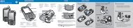
![MC55 Regulatory Guide [Spanish] (P/N 72-108860 ... - Enterprise](https://img.yumpu.com/14574395/1/190x133/mc55-regulatory-guide-spanish-p-n-72-108860-enterprise.jpg?quality=85)
![ES400 Regulatory Guide [Spanish] (P/N 72-134312-01ES Rev. A)](https://img.yumpu.com/14415156/1/190x127/es400-regulatory-guide-spanish-p-n-72-134312-01es-rev-a.jpg?quality=85)
![MC35 Regulatory Information [Spanish] - Symbol](https://img.yumpu.com/14415086/1/190x143/mc35-regulatory-information-spanish-symbol.jpg?quality=85)