LC-13B8U-S LC-15B8U-S LC-15B9U-SM
LC-13B8U-S LC-15B8U-S LC-15B9U-SM
LC-13B8U-S LC-15B8U-S LC-15B9U-SM

You also want an ePaper? Increase the reach of your titles
YUMPU automatically turns print PDFs into web optimized ePapers that Google loves.
<strong>LC</strong>-<strong>13B8U</strong>-S<br />
<strong>LC</strong>-<strong>15B8U</strong>-S<br />
<strong>LC</strong>-<strong>15B9U</strong>-<strong>SM</strong><br />
CAUTION: FOR CONTINUED<br />
PROTECTION AGAINST A RISK OF<br />
FIRE REPLACE ONLY WITH SAME<br />
TYPE F6700 (1.6A, 250V), F6702<br />
(1.6A, 250V), F7701 (3.15A, 250V)<br />
AND F7702 (3.15A, 250V) FUSE.<br />
1234567890123456789012345678901212345678901234567890123456789012123456789012345678901234567890121<br />
1234567890123456789012345678901212345678901234567890123456789012123456789012345678901234567890121<br />
1234567890123456789012345678901212345678901234567890123456789012123456789012345678901234567890121<br />
SAFETY NOTICE<br />
IMPORTANT SERVICE SAFETY PRECAUTION<br />
Ë Service work should be performed only by qualified service technicians who are thoroughly<br />
familiar with all safety checks and the servicing guidelines which follow:<br />
WARNING<br />
1. For continued safety, no modification of any circuit<br />
should be attempted.<br />
2. Disconnect AC power before servicing.<br />
A V<br />
BEFORE RETURNING THE RECEIVER<br />
(Fire & Shock Hazard)<br />
Before returning the receiver to the user, perform<br />
the following safety checks:<br />
1. Inspect all lead dress to make certain that leads are<br />
not pinched, and check that hardware is not lodged<br />
between the chassis and other metal parts in the<br />
receiver.<br />
2. Inspect all protective devices such as non-metallic<br />
control knobs, insulation materials, cabinet backs,<br />
adjustment and compartment covers or shields,<br />
isolation resistor-capacitor networks, mechanical<br />
insulators, etc.<br />
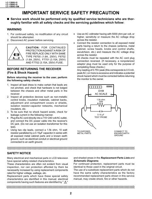
3. To be sure that no shock hazard exists, check for<br />
leakage current in the following manner.<br />
• Plug the AC cord directly into a 110~240 volt AC outlet,<br />
and connect the DC power cable into the receiver's<br />
DC jack. (Do not use an isolation transformer for this<br />
test).<br />
• Using two clip leads, connect a 1.5k ohm, 10 watt<br />
resistor paralleled by a 0.15µF capacitor in series with<br />
all exposed metal cabinet parts and a known earth<br />
ground, such as electrical conduit or electrical ground<br />
connected to an earth ground.<br />
Many electrical and mechanical parts in <strong>LC</strong>D television<br />
have special safety-related characteristics.<br />
These characteristics are often not evident from visual<br />
inspection, nor can protection afforded by them be<br />
necessarily increased by using replacement components<br />
rated for higher voltage, wattage, etc.<br />
Replacement parts which have these special safety<br />
characteristics are identified in this manual; electrical<br />
components having such features are identified by " å"<br />
12345678901234567890123456789012123456789012345678901234567890121234567890123456789012345678901212<br />
12345678901234567890123456789012123456789012345678901234567890121234567890123456789012345678901212<br />
12345678901234567890123456789012123456789012345678901234567890121234567890123456789012345678901212<br />
12345678901234567890123456789012123456789012345678901234567890121234567890123456789012345678901212<br />
2<br />
• Use an AC voltmeter having with 5000 ohm per volt, or<br />
higher, sensitivity or measure the AC voltage drop<br />
across the resistor.<br />
• Connect the resistor connection to all exposed metal<br />
parts having a return to the chassis (antenna, metal<br />
cabinet, screw heads, knobs and control shafts,<br />
escutcheon, etc.) and measure the AC voltage drop<br />
across the resistor.<br />
All checks must be repeated with the AC cord plug<br />
connection reversed. (If necessary, a nonpolarized<br />
adaptor plug must be used only for the purpose of<br />
completing these checks.)<br />
Any reading of 0.75V peak (this corresponds to 0.5 mA.<br />
peak AC.) or more is excessive and indicates a potential<br />
shock hazard which must be corrected before returning<br />
the monitor to the owner.<br />
TO EXPOSED<br />
METAL PARTS<br />
DVM<br />
AC SCALE<br />
1.5k ohm<br />
10W<br />
0.15 µF<br />
TEST PROBE<br />
CONNECT TO<br />
KNOWN EARTH<br />
GROUND<br />
and shaded areas in the Replacement Parts Lists and<br />
Schematic Diagrams.<br />
For continued protection, replacement parts must be<br />
identical to those used in the original circuit.<br />
The use of a substitute replacement parts which do not<br />
have the same safety characteristics as the factory<br />
recommended replacement parts shown in this service<br />
manual, may create shock, fire or other hazards.